Loading ...
Loading ...
Loading ...
Wiring
Specific wiring method
Outdoor
Unit
Outdoor
Unit
Outdoor
Unit
Outdoor
Unit
WARNING
ISOLATE THE POWER SUPPLY AND
COMMUNICATION LEADS AS SHOWN IN
THE DIAGRAM,KEEP POWER SUPPLY
LEADS AWAY FROM COMMUNICATION
LEADS.
CAUTION
• While connecng the wires, please strictly
follow the wiring diagram.
• The refrigerant circuit can become very
hot. Keep the interconnecon cable away
from the copper tube.
5. Clamp down the cable with the cable clamp.
The cable must not be loose or pull on the
u-lugs.
6. Reaach the electric box cover.
Refer to the wiring method of internal and
external machine communicaon and wired
controller as follows:
WARNING
Please refer to the wiring nameplate for the
wiring method. Do not connect the power
cord to the communicaon line, as this may
damage the system.
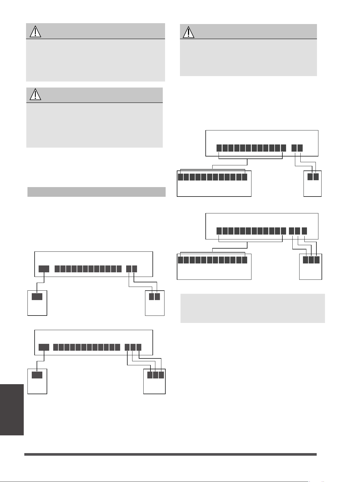
R C L G Y1
Y1/Y2
B W W2 EW1 DH
S1 S2
S1 S2
Indoor unit
Wired
controller
Wired
controller
R C L G Y1
Y1/Y2
B W W2 EW1 DH
L1(1) L2(2) S(3)
L1(1) L2(2) S(3)
Indoor unit
Wired
controller
Wired
controller
Connection method A:
(A)
(B)
Page 40
NOTE: The wiring method of the thermostat and
the internal machine refers to the wiring of the
non-communicaon scheme.
To use a 24V thermostat, you need to refer to the
following wiring:
L1(1) L2(2) S(3)
L1(1) L2(2) S(3)
24V thermostat
R C G Y1 Y2 B W W2 EW1 DH L
R C G Y1 Y2 B W W2 EW1 DH L
S1 S2
S1 S2
Indoor unit
24V thermostat
R C G Y1 Y2 B W W2 EW1 DH L
R C G Y1 Y2 B W W2 EW1 DH L
Indoor unit
Connection method B:
(A)
(B)
Loading ...
Loading ...
Loading ...