Loading ...
Loading ...
Loading ...
16
31-5000001 Rev. 6
ENGLISH
Step 3 - Installation of the Outdoor Unit (Cont.)
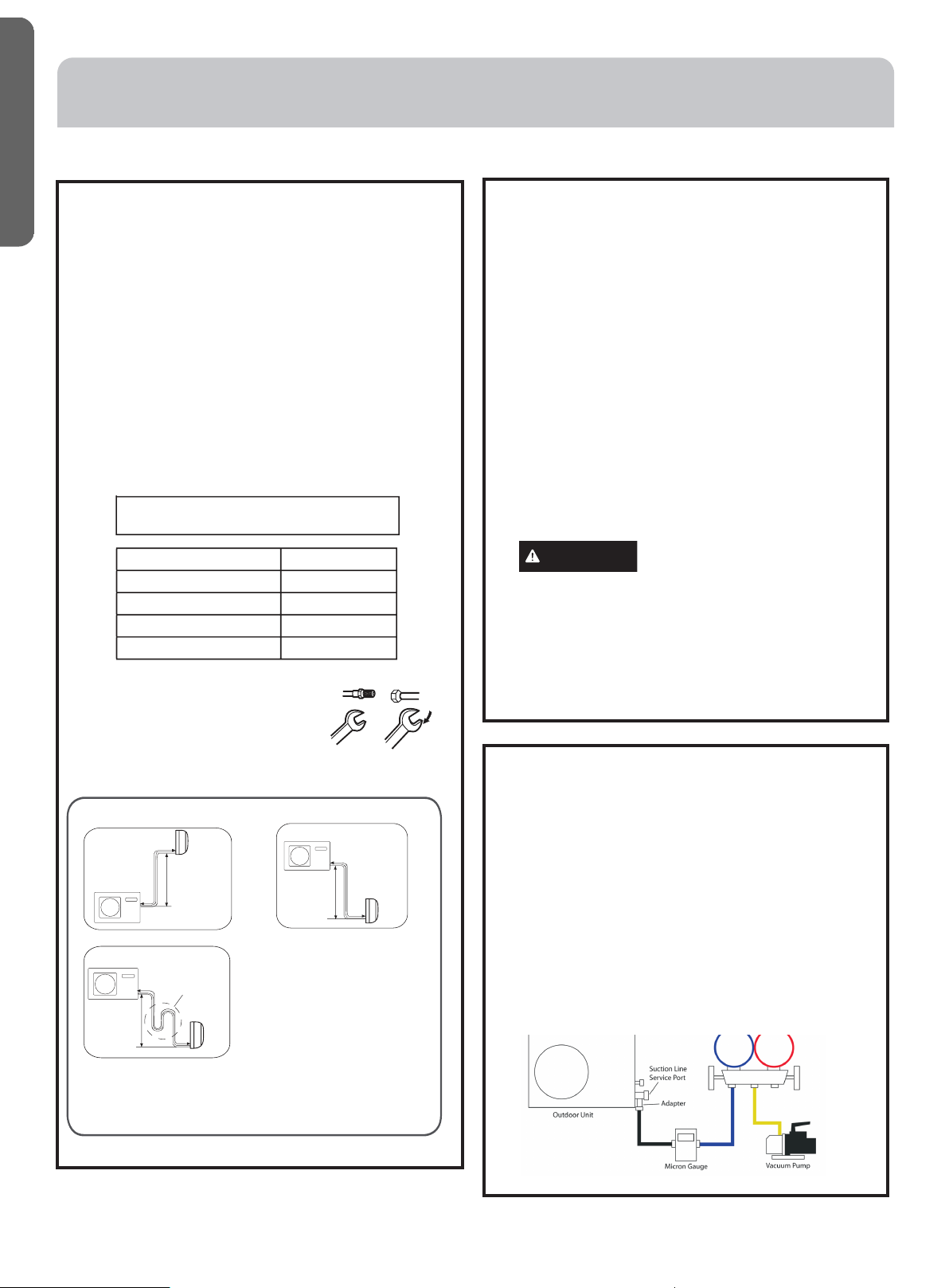
G. System Evacuation
NOTE– Do not open service valve.
• Remove the suction line cap and attach a manifold
gauge, micron gauge, and vacuum pump to
the suction line port using adapter AD-87 (see
illustration).
• Evacuate the system to at least 350 microns.
• Close the vacuum pump valve and check the micron
gauge. If the gauge rises above 150 microns in 60
seconds, the evacuation is incomplete or there
is a leak in the system. If the gauge does not rise
above 150 microns in 60 seconds, the evacuation is
complete.
• Once evacuation is complete, remove the adapter
and hose connection from the suction line port and
replaced the cap.
F. Leak Test
2U18MS* and 3U24MS* do not have master service
valves. Perform the following steps for EACH line set.
4U36MS*, 2U20EH*, 3U24EH*, and 4U36EH* have a
master service valve. Performing the following steps
will test ALL line sets.
• Remove the cap on the service valve.
• Using a tank of dry nitrogen and approved regulator,
charge the system with 150 psig of dry nitrogen
using mini-split adapter to connect the valve.
• Check for leaks at the flare fittings using soap
bubbles or another detection device. If a leak is
detected, make repairs to the fittings and recheck.
If no leaks are detected within 3 minutes, proceed.
• Using the same tank/regulator, charge the system
to 300 psig.
• Check for leaks as earlier. If no leaks are detected
within 3 minutes, proceed.
• Using the same tank/regulator, charge the system
to 500 psig.
• Check for leaks as earlier. Keep system pressurized
for at least 20 minutes.
WARNING
Do not use acetylene, oxygen or
compressed air or mixtures
containing air, oxygen, or combustible gases for
pressure testing. Do not use mixtures of hydrogen
containing refrigerant and air above atmospheric
pressure for pressure testing as they may become
flammable and could result in an explosion. Refrigerant,
when used as a trace gas, should only be mixed with dry
nitrogen for pressurizing units. Failure to follow these
recommendations could result in death or serious
injury as well as equipment or property damage.
E. Install Copper Lineset
• For 2U20EH2VH*, 2U18MS2VH*,
3U24EH2VH*, 3U24MS2VH*, 4U36MS2VH*,
and 4U36EH2VH* see table on page 15.
• Cut the line set to length.
• Place nut over the pipe and then flare with the
R-410A flaring tool.
NOTE: Follow standard practices for creating
pipe flares. When cutting and reaming the
tubing, use caution to prevent dirt or debris
from entering the tubing. Remember to place
nut over the tubing before flaring.
• To join the line set, directly align the tubing
flare to the fitting on the other pipe. Slide the
nut onto the fitting and hand tighten.
• Torque the fittings according to the
specifications shown in the torque chart below.
nut
ch
Forced fastening without careful centering may
damage the threads and cause a refrigerant leak.
Pipe Diameter(ǿ) Fastening torque
Liquid side6.35mm(1/4") 18N.m/13.3Ft.lbs
Liquid/Gas side9.52mm(3/8") 42 N.m/30.1Ft.lbs
Gas side 12.7mm(1/2") 55N.m/40.6Ft.lbs
Gas side 15.88mm(5/8") 60 N.m/44.3Ft.lbs
• Two wrenches are required to
join the flare connection; one
standard wrench and one torque
wrench adjusted to the proper
settings.
• Repeat the process for attaching
the other end of the line set.
Half union
Flare nut
Torque wrenc
h
Spanner
ǿ
Outdoor unit
Indoor unit
A
B
Outdoor unit
Indoor unit
A
B
A
B
Outdoor unit
Indoor unit
Oil trap
CAUTION*
Max. Elevation: A Max
= 33ft / 10m (09k / 12k)
= 50ft / 15m (18k / 24k)
In case the height of A is more than
15ft / 5m, an oil trap should be
installed every 16-23ft /5-7m
Max. Length: B Max
= 50ft / 15m (09k / 12k)
= 83ft / 25m (18k / 24k)
●
●
●
*NOTE: Oil trap is only required for
2U18MS2VH*, other multi-split systems
don’t require oil trap.
INSTALLATION INSTRUCTIONS
Loading ...
Loading ...
Loading ...