Loading ...
Loading ...
Loading ...
DEPTH OF CUT
Refer to Figure 7.
The depth of cut is adjusted by the relative positioning
of the infeed table with respect to the cutterhead. Infeed
table can be raised or lowered using the handwheel.
Turning the handwheel counterclockwise will lower the
infeed table causing more wood to be removed from
workpiece. Turning the handwheel clockwise will raise
the infeed table causing less wood to be removed from
workpiece.
Infeed Table
Depth of Cut
Hand Knob
Figure 7 - Depth of Cut
CHECK DEPTH OF CUT
Refer to Figure 8.
• Place a straight edge on the outfeed table extending
over the infeed table.
• Measure from the surface of the infeed table to the bot-
tom of the straight edge. This will be the depth of cut.
• Use locking knob on rear of jointer to secure infeed
table in position.
Outfeed. /'_'_ Max
. . Depth
Table "___
Figure 8 - Check Depthof Cut v-_
NOTE: This jointer/planer will make a maximum 5/64"
deep cut. To reduce the danger of kickback and possi-
ble injury, we recommend taking cuts of 1/16"or less.
CAUTION: Make sure the switch is in the OFF posi-
tion and the cord is unplugged from power source
before performing this check.
POSITIONING FENCE
Refer to Figure 9.
The fence can be adjusted to cut various angles from
0° to 45° outward.
To adjust fence position:
• Loosen fence locking handles from both sides of the
fence.
• Each fence segment has a positive set screw and
locking nut to stop fence at 0° (90° to table) and at
45° outward.
• Fence can be tilted to any desired angle within the
range.
• To lock fence, tighten the fence locking handles.
Locking Handle
Figure 9 - Adjust Fence
BLADE GUARD
The blade guard provides protection over the cutter-
head. It must always be in place and function properly.
Check the guard to make sure it functions properly. To
check:
• Pass a 1/_,,thick piece of wood over the cutterhead
between the guard and the fence. The guard will
spread and leave way for the wood piece to pass.
The guard must return to the original position auto-
matically when the wood piece is removed.
• Open the blade guard all the way until it stops, and
release it several times. It should always return to its
original position by spring action.
CAUTION: Ifthe blade guard fails to operate properly,
the spring must be replaced or adjusted.
• To replace spring, contact your nearest Sears store
or service center.
• To adjust or to assemble spring see "Adjusting Blade
Guard", page 9.
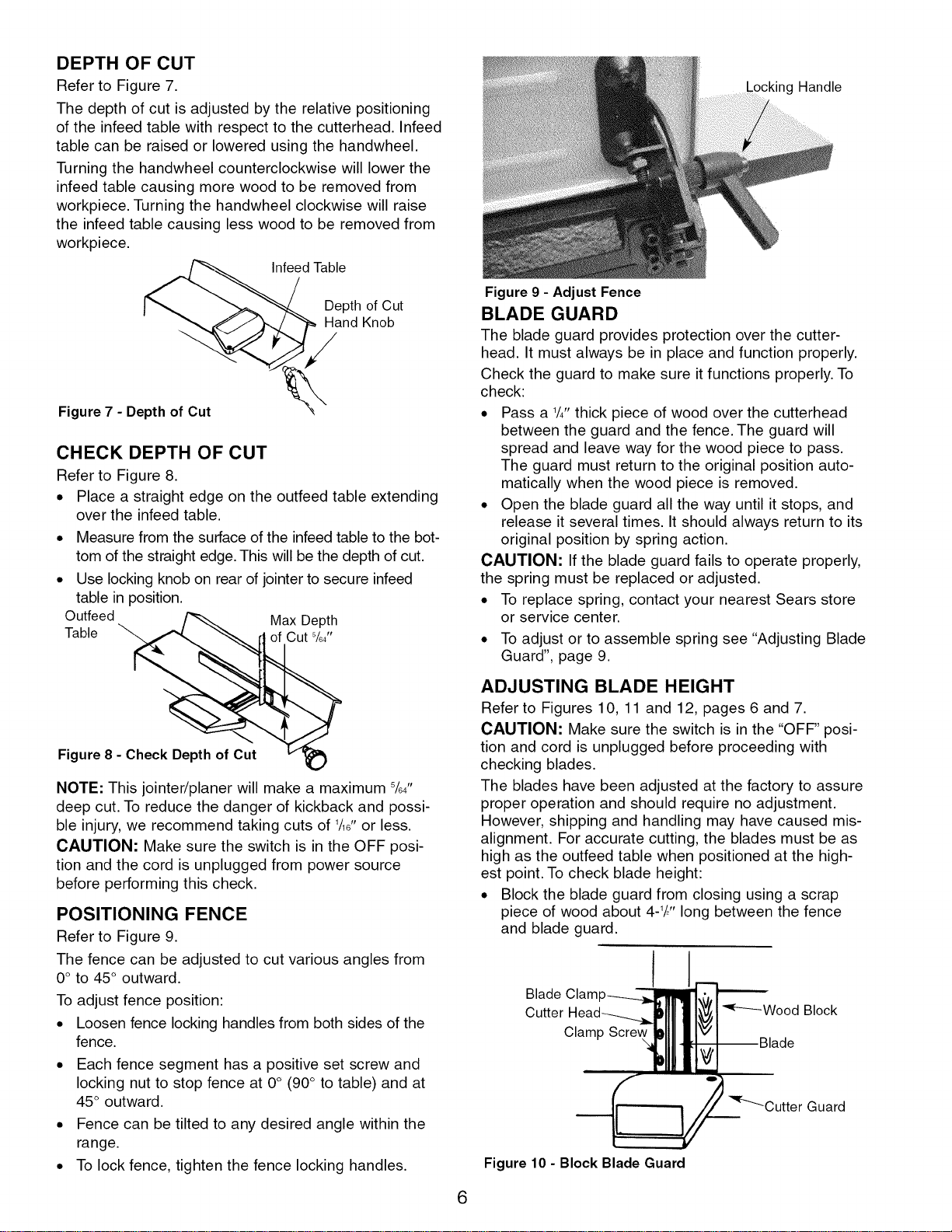
ADJUSTING BLADE HEIGHT
Refer to Figures 10, 11 and 12, pages 6 and 7.
CAUTION: Make sure the switch is in the "OFF" posi-
tion and cord is unplugged before proceeding with
checking blades.
The blades have been adjusted at the factory to assure
proper operation and should require no adjustment.
However, shipping and handling may have caused mis-
alignment. For accurate cutting, the blades must be as
high as the outfeed table when positioned at the high-
est point. To check blade height:
• Block the blade guard from closing using a scrap
piece of wood about 4-V_"long between the fence
and blade guard.
Blade Clam
Cutter
Clamp
Figure 10 - Block Blade Guard
6
Loading ...
Loading ...
Loading ...