
How to Hardwire a Dash Cam
The Hardwire Fuse Kit with Mini USB Bundle has everything you need to charge
your dash cam, cellphone, tablets or other devices from your car’s battery even if
your engine is off
。
It has low voltage protection so that you can use to power your dash camera 24
hours a day without draining your battery to dead.
Below are steps to install the hardwire kit:
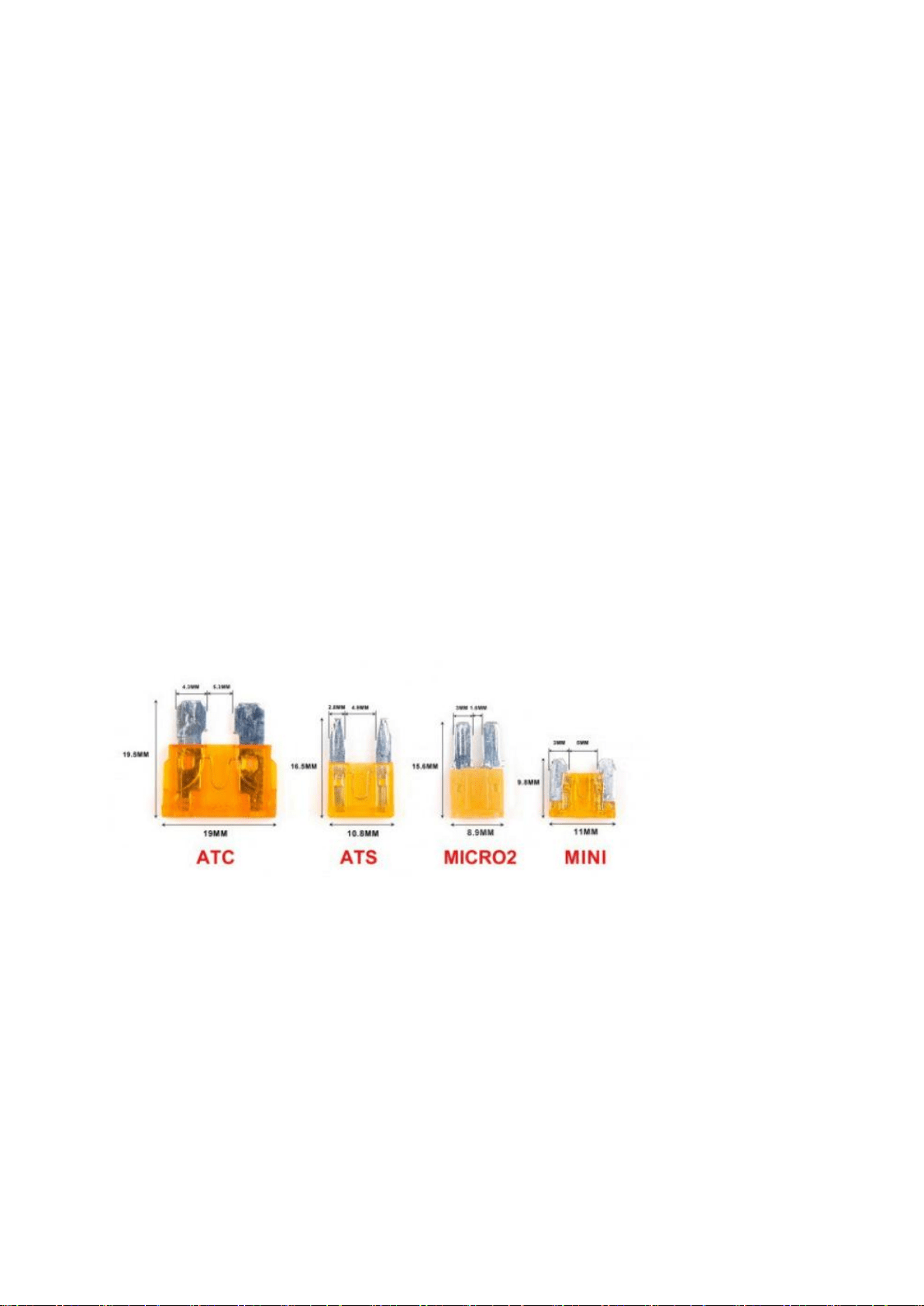
1. Identify your vehicle’s fuse type (important)
There are four main fuse types found in vehicles today,ATC, ATS,MICRO2,MINI,
The Mini is the most common fuse type, based on our observations.
Fuse boxes and fuse types vary not only from car to car, but also from year and
model. Therefore, it
’
s important to know which fuse type your car uses to ensure
that your dash cam installation kit can plug in to your fuse box, the best way to
know the exact fuse type that you need is to open your fuse box and take a look.
How to find your fuse box and discover which fuse type your car is?
1.1 Turn Your Car Off

Before doing any electrical work, ensure that your vehicle’s engine is turned off and
the key is completely removed from the ignition.
1.2 Find Your Owner’s Manual
1.3 Locate Your Fuse Box
Below is some examples about how to access the fuse box(different cars have
different ways), only for reference.
1.4 Remember the Fuse You’ll Remove
1.5 Carefully Remove a Fuse
1.6 Compare the Fuse to our Fuse Type Chart, and choose the right fuse type of
yours.
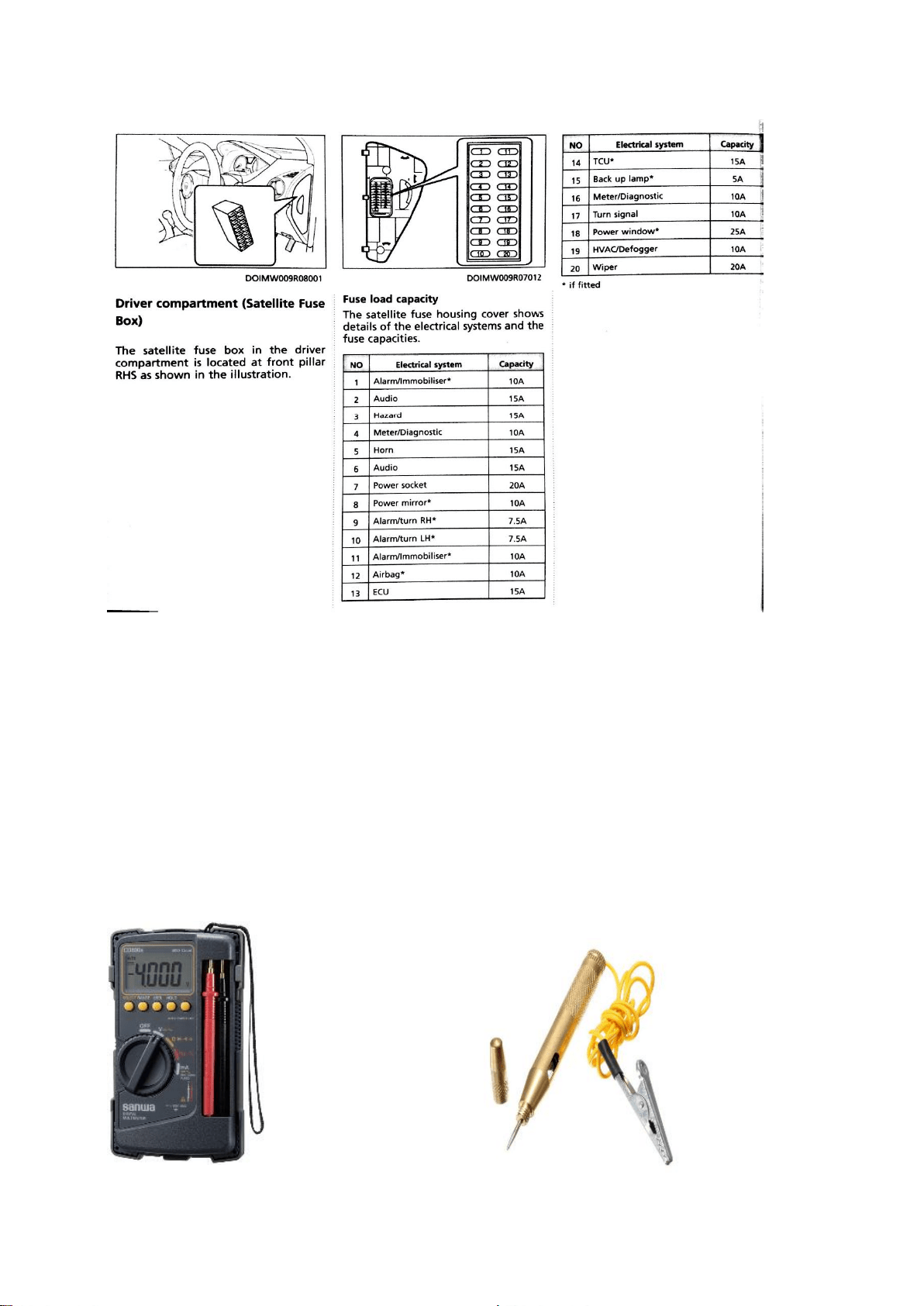
2. Identify which fuse is ACC and Battery. Example referring to below interior fuse
box diagram
:
Note: Strongly advised not to connect hardwire kits wire to any of fuse’s related to vehicle
safety system.
Recommended to choose as below:
Acc signal: Fuse No. 6 Audio, Fuse No. 7 Power Socket or Fuse No. 8 Power Mirror.
Battery signal: Fuse No. 2 Audio, Fuse No. 3 Hazard.
After located the fuse point, you need to double confirm whether the fuse is
providing the signal as we needed.
To confirm the signal, you will need below tools:
Please refer to below ignition switch diagram example as below;
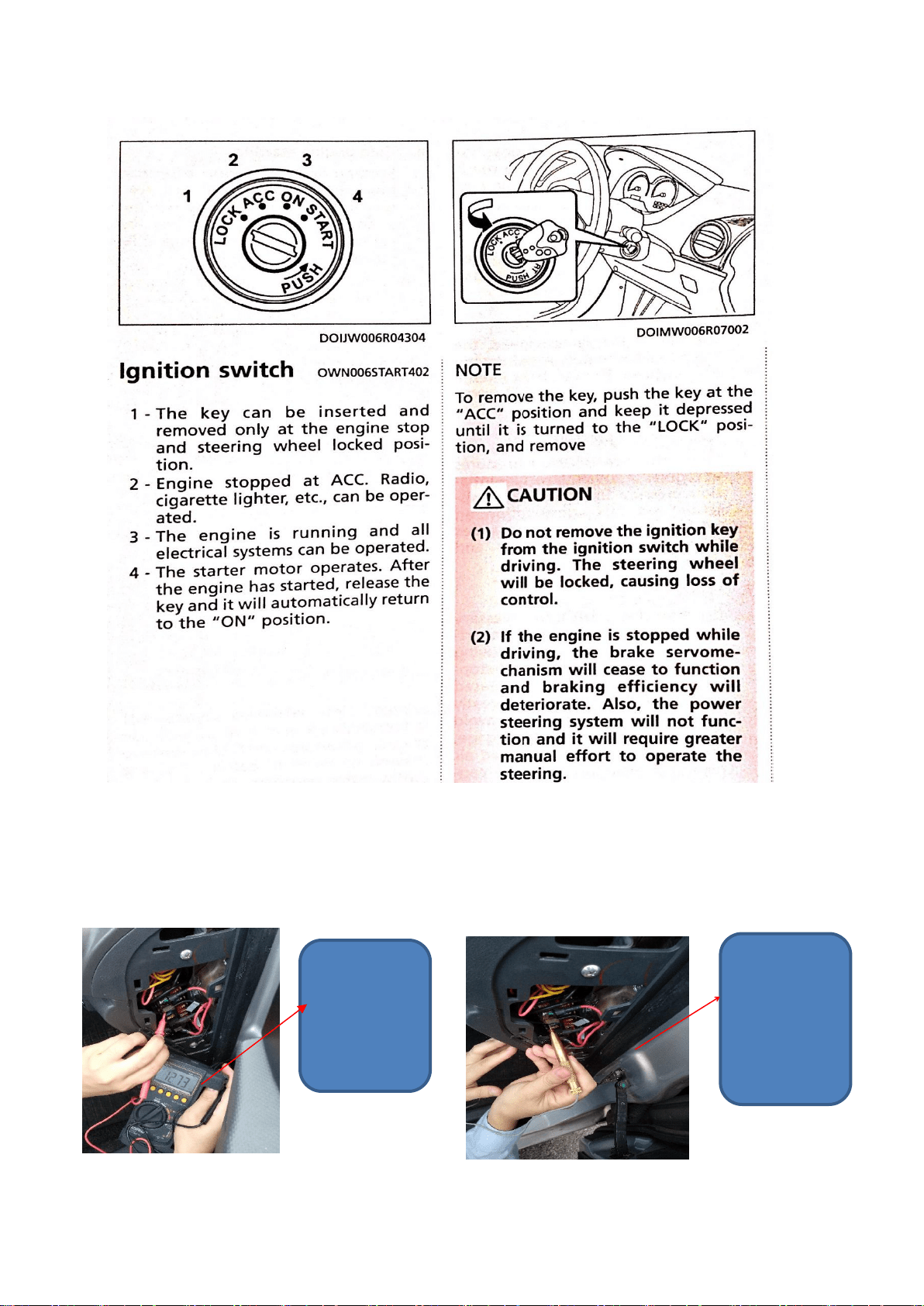
To confirm Battery signal, Ignition Switch position must be in lock position,
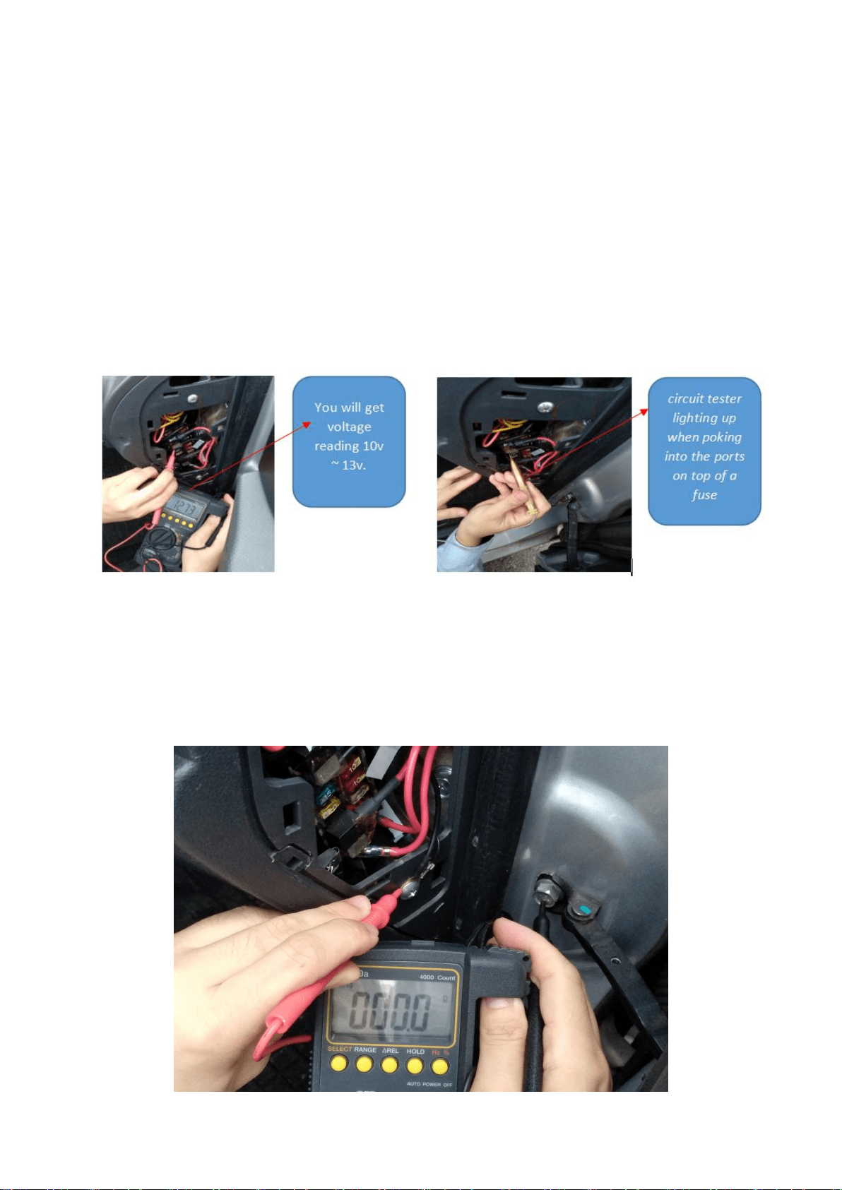
You will get
voltage
reading 10v ~
13v.
circuit tester
lighting up
when poking
into the ports
on top of a
fuse
To confirm ACC signal, Ignition Switch position must be in ACC position. You
should get voltage reading on multimeter or light up on circuit tester. Reconfirm the
fuse slot again with Ignition Switch position in Lock position and recheck the fuse
slot using multimeter or circuit tester. You should not get any voltage reading on
your multimeter or circuit tester not light up during Ignition Switch in Lock
position.
To confirm ground point, refer to below picture; use multimeter to check continuity
mode. Find any screw direct tighten to vehicle body and measured the screw point
against the vehicle body. A good ground point must get continuity reading at < 0.1
ohm.
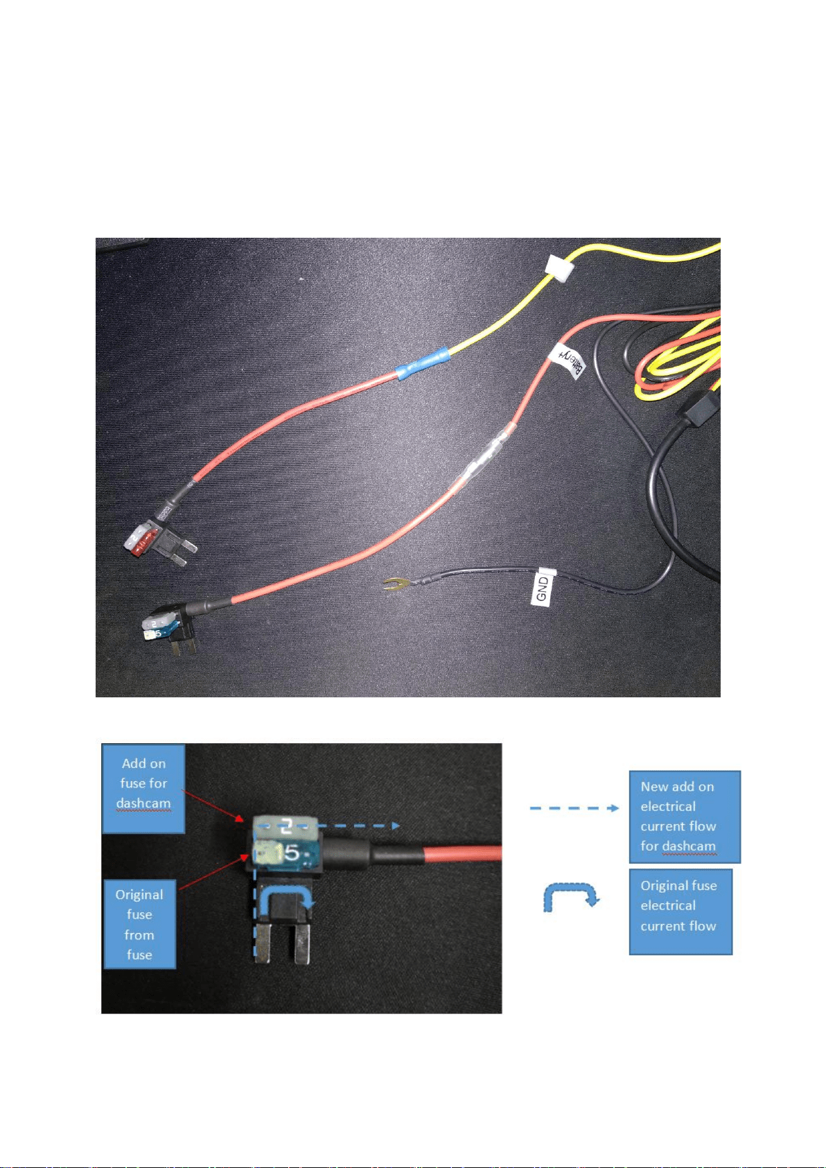
Now you have determined the ACC signal, Battery signal and ground connection
point. It’s time to connect your hardwire kits to your vehicle electrical system on the
interior fuse.
Note: Refer below for fuse tap electrical flow as per picture below;