
Loading ...
Loading ...
Loading ...
13
Majestic • ECHEL36IN, ECHEL36STIN, ECHEL48IN, ECHEL48STIN, ECHEL60IN, ECHEL72IN Owner’s Manual • 2406-971 Rev. B • 10/16
NOTICE: Some functionality will be lost when using
battery backup including remote control, lights, or any
other auxiliary functions that require household 110-120
VAC power.
I. Operation During A Power Outage
NOTICE: Batteries should only be used as a power source
in the event of an emergency power outage. Batteries
should not be used as a primary long-term power source.
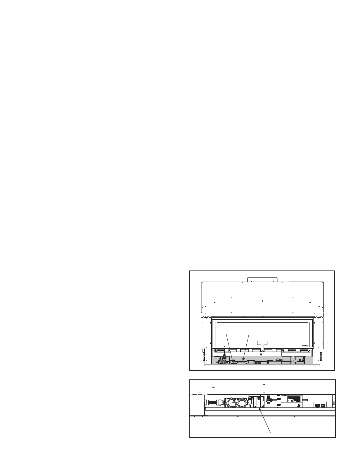
3.6 Control Cavity Location
BATTERY TRAY
3.7 Battery Tray Location - Top View
CONTROL CAVITY
(Shown in gray)
BATTERY
TRAY
CONTROL
MODULE
The IntelliFire™ Plus intermittent pilot ignition system
comes with a battery backup system that enables the
system to operate in a power outage. The system offers
seamless transition from household AC power to battery
backup. A factory-installed battery pack is located in the
control cavity of the appliance. See Figure 3.6. Battery
longevity and performance will be affected by long term
exposure to the service temperatures of this appliance.
To Operate Fireplace Using Battery Power (DC):
1. Access the control cavity of the appliance. See Figure
3.6 for location. Lift the decorative front off of the
appliance and lift the vanity panel out of the bottom of
the glass frame.
2. Locate the battery tray and insert four AA cell batteries.
See Figure 3.7. Battery polarity must be correct or
module damage will occur. A complete wiring diagram
is included in the Electrical section of the appliance
Installation Manual.
3. Turn the appliance on according to the instructions
below for the appropriate type of control:
Standard Wall Switch or Factory-Installed ON/OFF
Switch:
• Toggle the switch as you would under normal
circumstances.
Wireless Remote:
• Remote receiver is integrated into the ignition module
• Use the remote to turn the appliance on.
• To preserve battery life, do not use the HI/LO fl ame or
THERMOSTAT options.
Ignition Module:
• Remove screws on left and right sides of component
heat shield and lift it out of the control cavity.
• Locate the ignition module in the control cavity.
• Slide the ON/REMOTE/OFF switch to the ON position.
• Reinstall component heat shield.
To Return to Operation Using Electrical (AC) Power
CAUTION! Risk of Overheating! Component heat shield
MUST be installed before operating appliance. Electrical
components will be damaged.
Standard Wall Switch or Factory-Installed ON/OFF
Switch:
• Remove screws on left and right sides of component
heat shield and lift it out of the control cavity.
• Toggle the switch to OFF.
• Remove the batteries from the battery tray.
• Reinstall component heat shield.
• Replace bottom glass shield and decorative front on
appliance.
Wireless Remote:
• Remove screws on left and right sides of component
heat shield and lift it out of the control cavity.
• Slide the ON/REMOTE/OFF switch to the REMOTE
position.
• Remove the batteries from the battery tray.
• Reinstall component heat shield.
• . Replace bottom glass shield and decorative front on
appliance.
Ignition Module:
• Remove screws on left and right sides of component
heat shield and lift it out of the control cavity.
• Slide the ON/REMOTE/OFF switch to the REMOTE
position.
• Remove the batteries from the battery tray.
• Reinstall component heat shield.
• . Replace bottom glass shield and decorative front on
appliance.
Loading ...
Loading ...
Loading ...