
Loading ...
Loading ...
Loading ...
MAINTENANCE SCHEDULE
Perform these required maintenance procedures at the
frequency stated in the table. These procedures should
also be a part of any seasonal tune-up.
NOTE: Some maintenance procedures may require
special tools or skills. If you are unsure about
these procedures take your unit to any non-road
engine repair establishment, individual or
authorized service dealer.
WARNING: To prevent serious inJury'never
perform maintenance or repairs with unit
running. Always service and repair a cool unit. I
Disconnect the spark plug wire to ensure that I
the unit cannot start. J
NOTE: Maintenance, replacement, or repair of the
emission control devices and system may be
performed by any non-road engine repair
establishment, individual or authorized service
dealer.
In order to assure peak performance of your engine,
inspection of the engine exhaust port may be necessary
after 50 hours of operation. If you notice lost RPM, poor
performance or general lack of acceleration, this service
may be required. If you feel your engine is in need of this
inspection, refer service to any non-road engine repair
establishment, individual or authorized service dealer for
repair. DO NOT attempt to perform this process yourself
as engine damage may result from contaminants
involved in the cleaning process for the port.
Before starting engine Fill fuel tank with fresh fuel Page 9
Every 10 hours Clean and re-oil air filter Page 16
.... Check and clean spark arrestor Page 17
Every zb nours Check spark plug condition and gap Page 18
Every 50 hours Inspect exhaust port and spark arrestor screen for clogging or _ 17
obstruction to assure maximum performance levels . _'age
LINE INSTALLATION FOR THE SPEEDSPOOL _
WARNING: Never use metal-rei nforced
line, wire, chain or ropel These can break
off and become dangerous project les: J
Always use Genuine Factory Parts TM 0.080 inch (2.03
mm) replacement line. Lines other than those specified
may make the engine overheat or fail.
There are two methods to replace the SpeedSpool ®
trimming line:
• Wind the inner reel with new line
• Install a pre-wound inner reel
Winding the Inner Reel With New Line
NOTE: It Is unnecessary to remove the bump knob to
install a new trimming line.
1. Cut two pieces of 0.080 inch (2.03 mm) trimming
line, 10 feet (3 m) long.
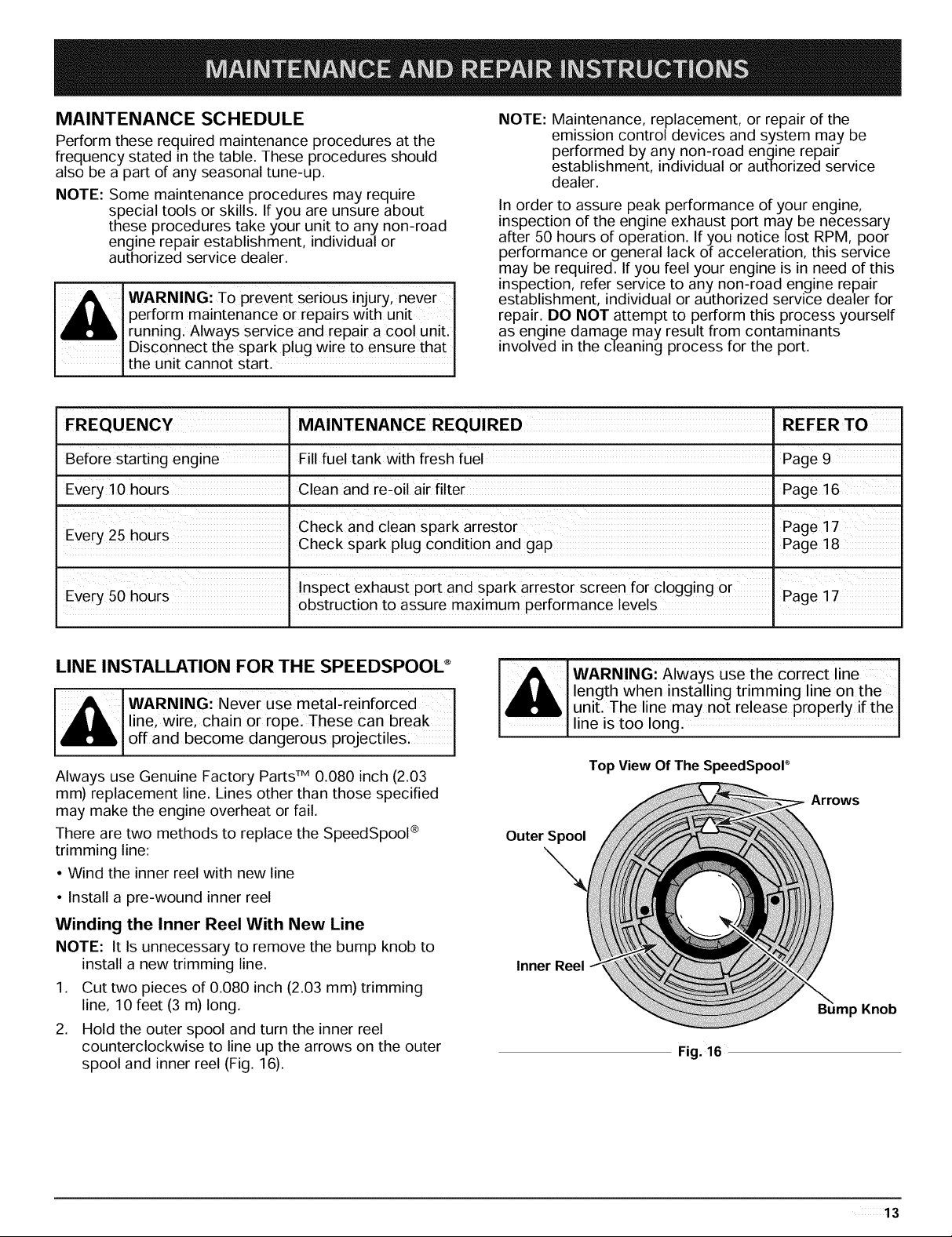
2. Hold the outer spool and turn the inner reel
counterclockwise to line up the arrows on the outer
spool and inner reel (Fig. 16).
WARNING:Always use the Correct line
length when installing trimming line on the
unit. The line may not release properly if the
line is too long.
Top View Of The SpeedSpoor
Arrows
Outer Spool
Inner Reel
p Knob
Fig. 16
13
Loading ...
Loading ...
Loading ...