USER GUIDE
SAFETY • INSTALLATION & INTEGRATION • OPERATING INSTRUCTIONS • MAINTENANCE • SERVICE
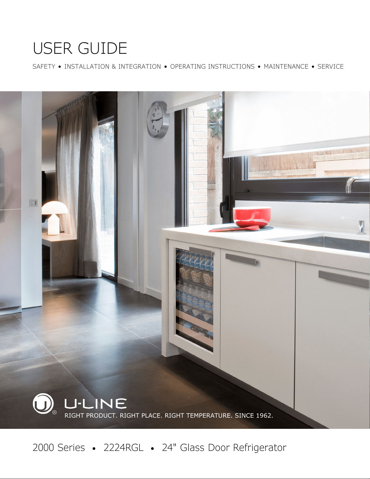
2000 Series •
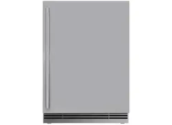
2224RGL •
24" Glass Door Refrigerator
RIGHT PRODUCT. RIGHT PLACE. RIGHT TEMPERATURE. SINCE 1962.
USER GUIDE
u-line.com
Contents
SAFETY • INSTALLATION & INTEGRATION • OPERATING INSTRUCTIONS • MAINTENANCE • SERVICE
Intro
Safety
Safety and Warning
Disposal and Recycling
Installation
Environmental Requirements
Electrical
Cutout Dimensions
Product Dimensions
Side by Side Installation
Anti-Tip Bracket
General Installation
Integrated Grille / Plinth Dimensions
Grille / Plinth Installation
Door Swing
Door Stop
Door Adjust
Operating Instructions
First Use
Control Operation
Sabbath Mode
Airflow and Product Loading
Interior Shelves
Refrigerator Bins / Crisper
Maintenance
Cleaning
Cleaning Condenser
Extended Non-Use
Service
Troubleshooting
Warranty
USER GUIDE
Introduction 1
u-line.com
WELCOME TO U-LINE
Congratulations on your U-Line purchase. Your product comes from a company with over five decades and three generations
of premium modular ice making, refrigeration, and wine preservation experience. U-Line continues to be the American
leader, delivering versatility and flexibility for multiple applications including residential, light commercial, outdoor and marine
use. U-Line’s complete product collection includes modular Wine Captain
®
Models, Beverage Centers, Clear Ice Machines,
Crescent Ice Makers, Glass & Solid Door Refrigerators, Drawer Models, Freezers, and Combo
®
Models.
U-Line has captivated those with an appreciation for the finer things with exceptional functionality, style, inspired innovations
and attention to even the smallest details. We are known and respected for our unwavering dedication to product design,
quality and selection. U-Line is headquartered in Milwaukee, Wisconsin and has shipped product to five continents for over
two decades and is proud to have the opportunity to ship to you.
PRODUCT INFORMATION
Looking for additional information on your product? User Guides, Quick Reference Guides, CAD Drawings, Compliance
Documentation, and Product Warranty information are all available for reference and download at u-line.com.
PROPERTY DAMAGE / INJURY CONCERNS
In the unlikely event property damage or personal injury is suspected related to a U-Line product, please take the following
steps:
1. U-Line Customer Care must be contacted immediately at +1.800.779.2547.
2. Service or repairs performed on the unit without prior written approval from U-Line is not permitted. If the unit has been
altered or repaired in the field without prior written approval from U-Line, claims will not be eligible.
SERVICE INFORMATION
Answers to Customer Frequently Asked Questions are available at u-line.com under Customer Care or you may contact our
Customer Care group directly, contact information below.
GENERAL INQUIRIES
U-Line Corporation
8900 N. 55th Street
Milwaukee, Wisconsin 53223 USA
Monday - Friday 8:00 am to 4:30 pm CST
T: +1.414.354.0300
F: +1.414.354.7905
Email: sales@u-line.com
u-line.com
SERVICE & PARTS ASSISTANCE
Monday - Friday 8:00 am to 5:30 pm CST
T: +1.800.779.2547
F: +1.414.354.5696
Service Email: onlineservice@u-line.com
Parts Email: onlineparts@u-line.com
CONNECT WITH US
Designed, engineered and assembled in WI, USA
USER GUIDE
Safety and Warning 1
u-line.com
SAFETY • INSTALLATION & INTEGRATION • OPERATING INSTRUCTIONS • MAINTENANCE • SERVICE
Safety and Warning
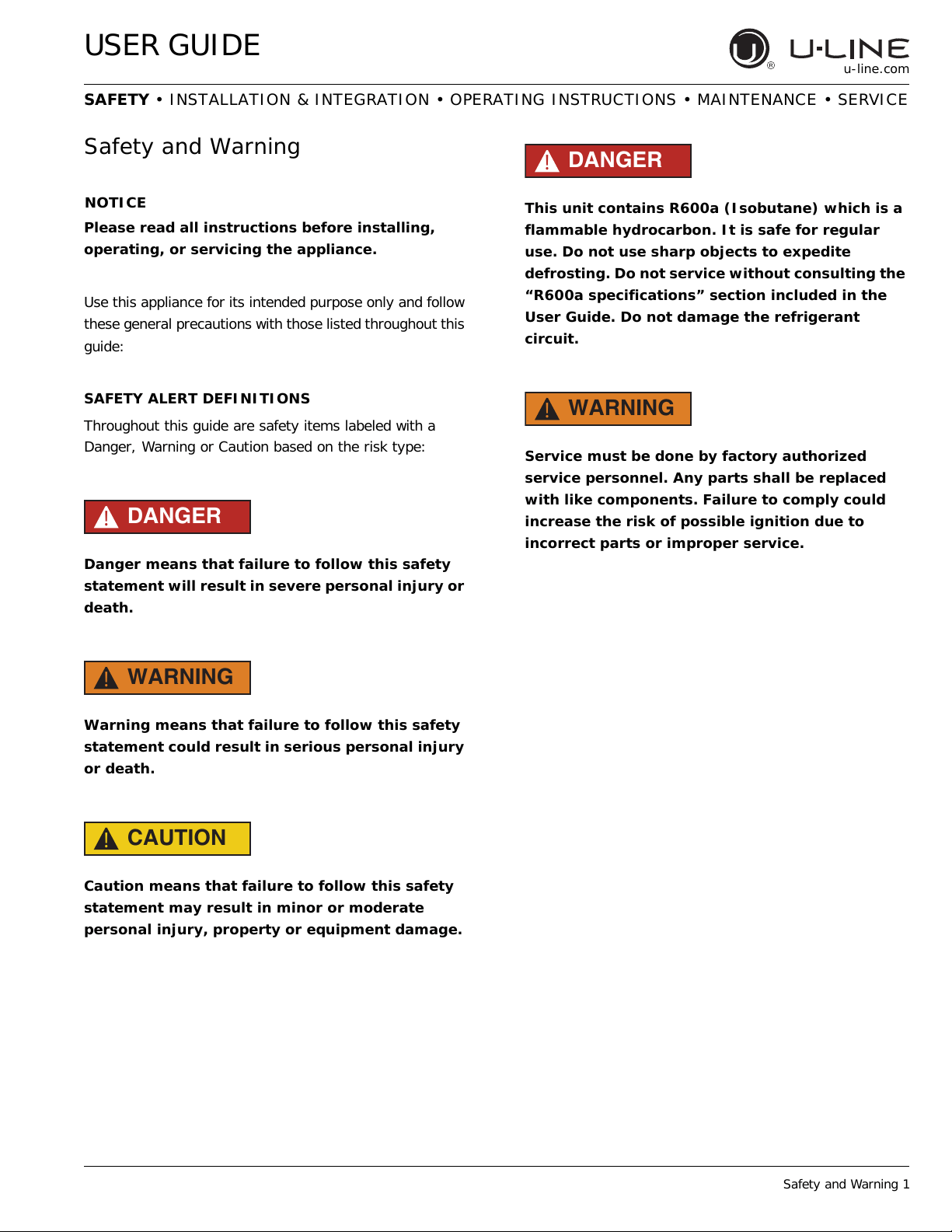
NOTICE
Please read all instructions before installing,
operating, or servicing the appliance.
Use this appliance for its intended purpose only and follow
these general precautions with those listed throughout this
guide:
SAFETY ALERT DEFINITIONS
Throughout this guide are safety items labeled with a
Danger, Warning or Caution based on the risk type:
DANGER
!
Danger means that failure to follow this safety
statement will result in severe personal injury or
death.
WARNING
!
Warning means that failure to follow this safety
statement could result in serious personal injury
or death.
CAUTION
!
Caution means that failure to follow this safety
statement may result in minor or moderate
personal injury, property or equipment damage.
DANGER
!
This unit contains R600a (Isobutane) which is a
flammable hydrocarbon. It is safe for regular
use. Do not use sharp objects to expedite
defrosting. Do not service without consulting the
“R600a specifications” section included in the
User Guide. Do not damage the refrigerant
circuit.
WARNING
!
Service must be done by factory authorized
service personnel. Any parts shall be replaced
with like components. Failure to comply could
increase the risk of possible ignition due to
incorrect parts or improper service.
USER GUIDE
Disposal and Recycling 1
u-line.com
SAFETY • INSTALLATION & INTEGRATION • OPERATING INSTRUCTIONS • MAINTENANCE • SERVICE
Disposal and Recycling
DANGER
!
RISK OF CHILD ENTRAPMENT. Before you throw
away your old refrigerator or freezer, take off
the doors and leave shelves in place so children
may not easily climb inside.
If the unit is being removed from service for disposal,
check and obey all federal, state and local regulations
regarding the disposal and recycling of refrigeration
appliances, and follow these steps completely:
1. Remove all consumable contents from the unit.
2. Unplug the electrical cord from its socket.
3. Remove the door(s)/drawer(s).
USER GUIDE
Environmental Requirements 1
u-line.com
SAFETY • INSTALLATION & INTEGRATION • OPERATING INSTRUCTIONS • MAINTENANCE • SERVICE
Environmental Requirements
This model is intended for indoor/interior applications only
and is not to be used in installations that are open/
exposed to natural elements.
This unit is designed to operate between 50°F (10°C) and
100°F (38°C). Higher ambient temperatures may reduce
the unit’s ability to reach low temperatures and/or reduce
ice production on applicable models.
For best performance, keep the unit out of direct sunlight
and away from heat generating equipment.
In climates where high humidity and dew points are
present, condensation may appear on outside surfaces.
This is considered normal. The condensation will
evaporate when the humidity drops.
CAUTION
!
Damages caused by ambient temperatures of
40°F (4°C) or below are not covered by the
warranty.
USER GUIDE
Electrical 1
u-line.com
SAFETY • INSTALLATION & INTEGRATION • OPERATING INSTRUCTIONS • MAINTENANCE • SERVICE
Electrical
WARNING
!
SHOCK HAZARD — Electrical Grounding
Required. Never attempt to repair or perform
maintenance on the unit until the electricity has
been disconnected.
Never remove the round grounding prong from
the plug and never use a two-prong grounding
adapter.
Altering, cutting or removing power cord,
removing power plug, or direct wiring can cause
serious injury, fire, loss of property and/or life,
and will void the warranty.
Never use an extension cord to connect power to
the unit.
Always keep your working area dry.
NOTICE
Electrical installation must observe all state and
local codes. This unit requires connection to a
grounded (three-prong), polarized receptacle
that has been placed by a qualified electrician.
The unit requires a grounded and polarized 115 VAC,
60 Hz, 15A power supply (normal household current). An
individual, properly grounded branch circuit or circuit
breaker is recommended. A GFCI (ground fault circuit
interrupter) is usually not required for fixed location
appliances and is not recommended for your unit because
it could be prone to nuisance tripping. However, be sure
to consult your local codes.
See CUTOUT DIMENSIONS for recommended receptacle
location.
USER GUIDE
Cutout Dimensions 1
u-line.com
SAFETY • INSTALLATION & INTEGRATION • OPERATING INSTRUCTIONS • MAINTENANCE • SERVICE
Cutout Dimensions
PREPARE SITE
Your U-Line product has been designed exclusively for a
built-in installation. When built-in, your unit does not
require additional air space for top, sides, or rear.
However, the front grille (plinth strip/base fascia) must
NOT be obstructed.
CAUTION
!
Unit can NOT be installed behind a closed cabinet
door.
U-Line products are designed and manufactured
to be installed in the specified cutout openings
shown, and variance to the floors or cabinetry
must be accounted for in your installation.
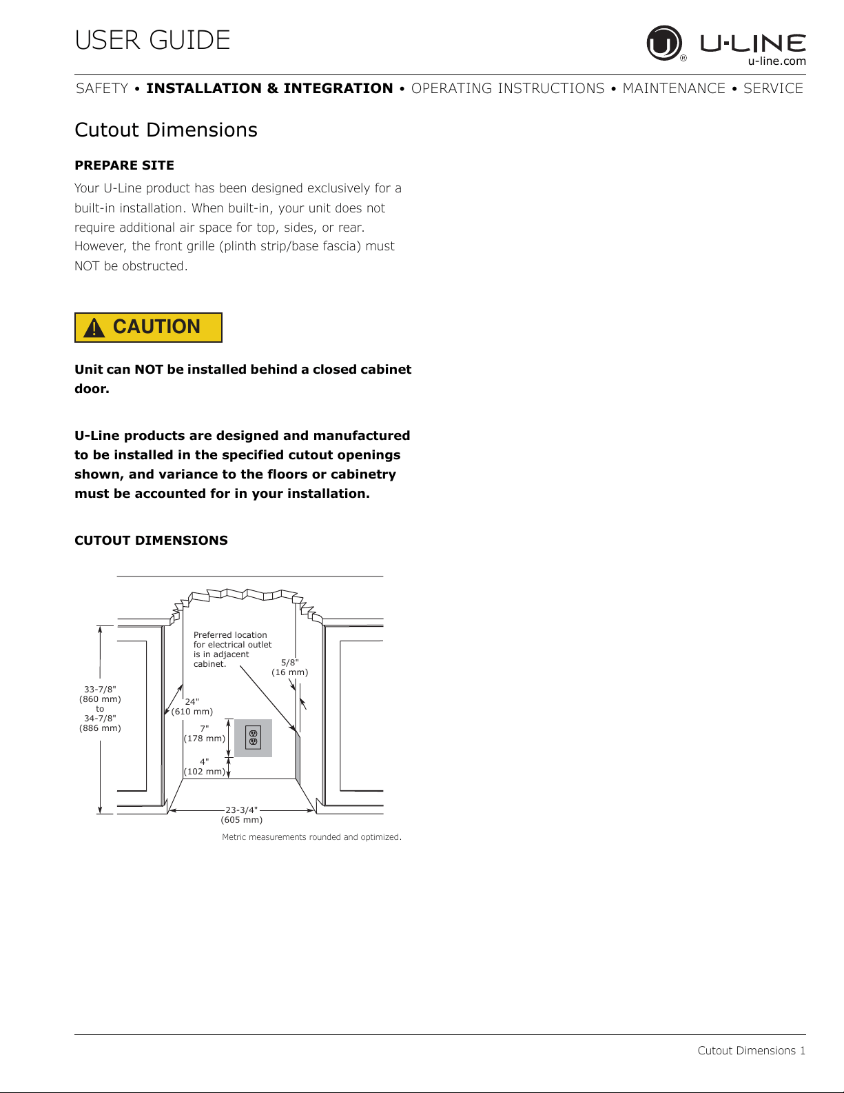
CUTOUT DIMENSIONS
Metric measurements rounded and optimized.
4"
(102 mm)
7"
(178 mm)
33-7/8"
(860 mm)
to
34-7/8"
(886 mm)
23-3/4"
(605 mm)
Preferred location
for electrical outlet
is in adjacent
cabinet.
24"
(610 mm)
5/8"
(16 mm)
USER GUIDE
Product Dimensions 1
u-line.com
SAFETY • INSTALLATION & INTEGRATION • OPERATING INSTRUCTIONS • MAINTENANCE • SERVICE
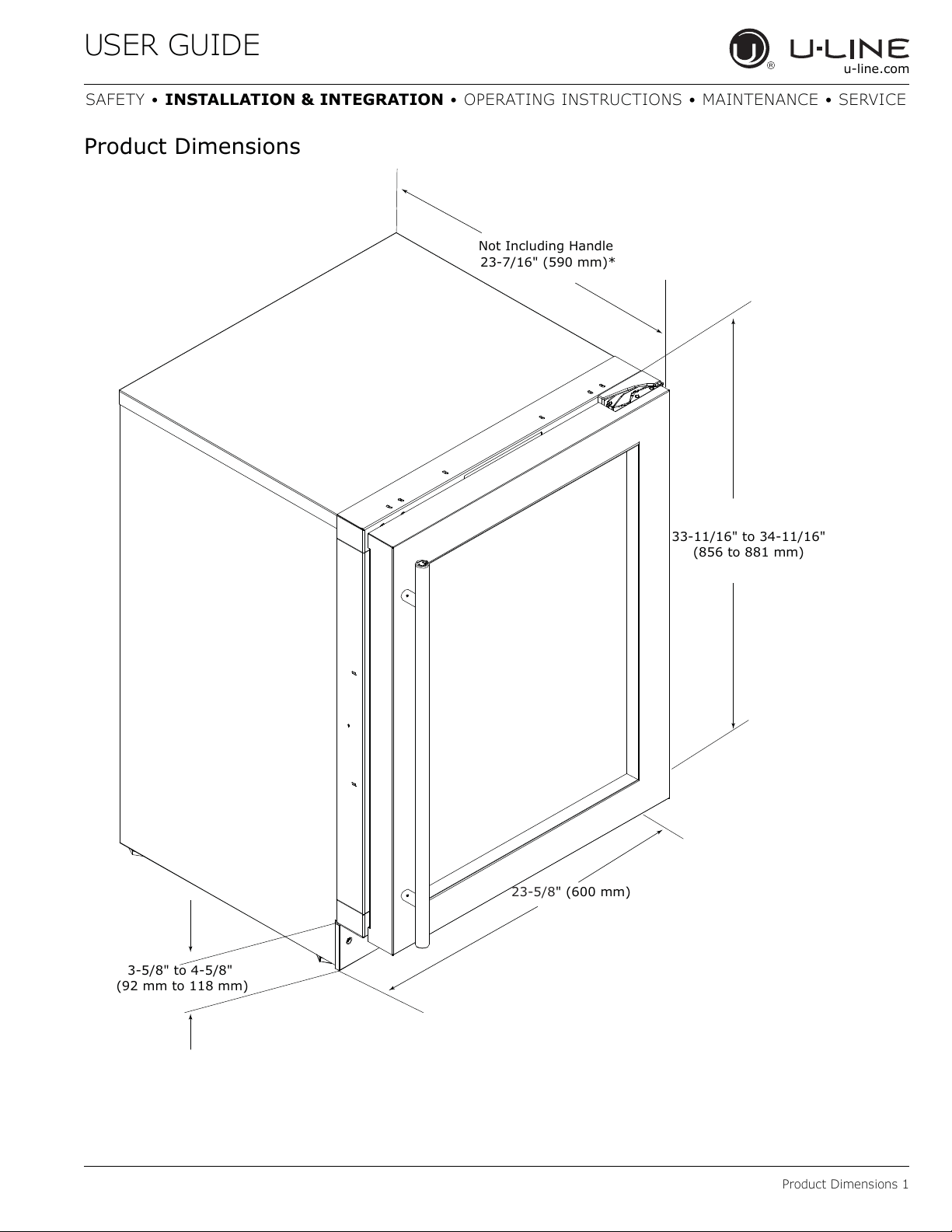
Product Dimensions
3-5/8" to 4-5/8"
(92 mm to 118 mm)
33-11/16" to 34-11/16"
(856 to 881 mm)
23-5/8" (600 mm)
Not Including Handle
23-7/16" (590 mm)*
USER GUIDE
Side-by-Side Installation 1
u-line.com
SAFETY • INSTALLATION & INTEGRATION • OPERATING INSTRUCTIONS • MAINTENANCE • SERVICE
Side-by-Side Installation
OTHER SITE REQUIREMENTS
Side-by-Side Installation
Units must operate from separate, properly grounded
electrical receptacles placed according to each unit’s
electrical specifications requirements.
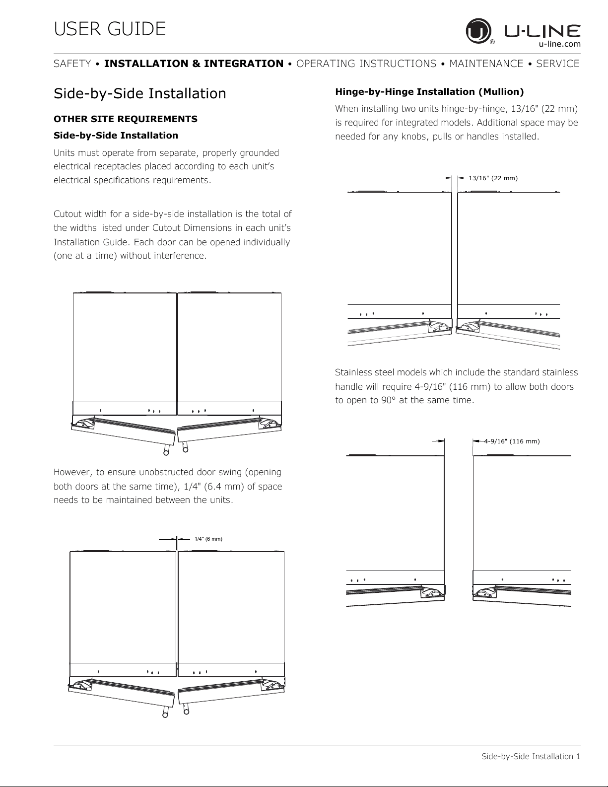
Cutout width for a side-by-side installation is the total of
the widths listed under Cutout Dimensions in each unit’s
Installation Guide. Each door can be opened individually
(one at a time) without interference.
However, to ensure unobstructed door swing (opening
both doors at the same time), 1/4" (6.4 mm) of space
needs to be maintained between the units.
Hinge-by-Hinge Installation (Mullion)
When installing two units hinge-by-hinge, 13/16" (22 mm)
is required for integrated models. Additional space may be
needed for any knobs, pulls or handles installed.
Stainless steel models which include the standard stainless
handle will require 4-9/16" (116 mm) to allow both doors
to open to 90° at the same time.
1/4" (6 mm)
13/16" (22 mm)
4-9/16" (116 mm)
USER GUIDE
Anti-Tip Bracket 1
u-line.com
SAFETY • INSTALLATION & INTEGRATION • OPERATING INSTRUCTIONS • MAINTENANCE • SERVICE
Anti-Tip Bracket
CAUTION
!
The anti-tip bracket must be installed to prevent
the unit from tipping when doors are fully
opened or excess weight is placed on the front of
the unit.
The anti-tip bracket has multiple mounting options.
Mounting will depend on your particular cabinet
configuration. Locate 3 #8x5/8" screws included with your
unit.
TOP MOUNT
For ease of installation, the anti-tip bracket is pre-installed
in the top mount position.
1. Completely slide the unit into its position in the
cabinet. Be certain unit height is properly adjusted.
(See GENERAL INSTALLATION).
2. Open door completely. Make certain door clears
surrounding cabinetry.
3. Using a 3/32" (2.50 mm) drill bit, drill 3 pilot holes 5/8"
(16 mm) deep into bottom of counter top. Use the
anti-tip bracket as a template.
4. Install 3 #8x5/8" screws into the plate using a
#2 Phillips head screwdriver.
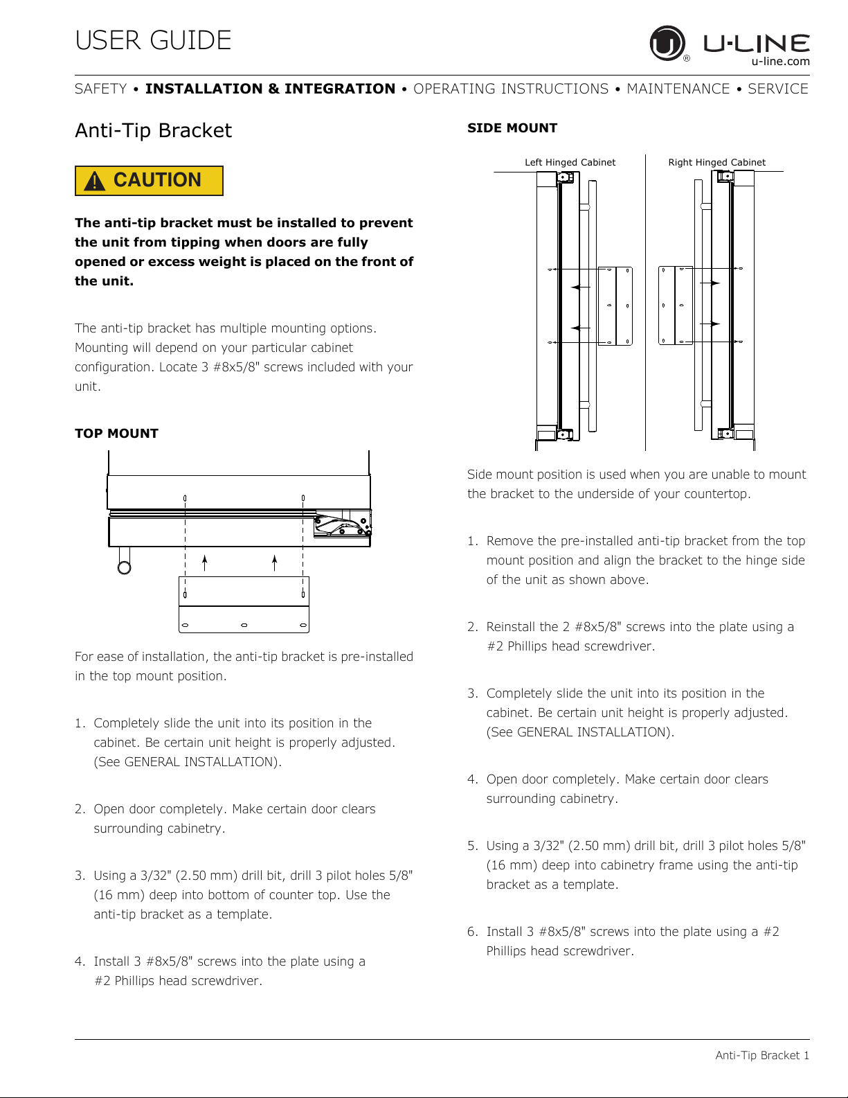
SIDE MOUNT
Side mount position is used when you are unable to mount
the bracket to the underside of your countertop.
1. Remove the pre-installed anti-tip bracket from the top
mount position and align the bracket to the hinge side
of the unit as shown above.
2. Reinstall the 2 #8x5/8" screws into the plate using a
#2 Phillips head screwdriver.
3. Completely slide the unit into its position in the
cabinet. Be certain unit height is properly adjusted.
(See GENERAL INSTALLATION).
4. Open door completely. Make certain door clears
surrounding cabinetry.
5. Using a 3/32" (2.50 mm) drill bit, drill 3 pilot holes 5/8"
(16 mm) deep into cabinetry frame using the anti-tip
bracket as a template.
6. Install 3 #8x5/8" screws into the plate using a #2
Phillips head screwdriver.
Left Hinged Cabinet
Right Hinged Cabinet
USER GUIDE
General Installation 1
u-line.com
SAFETY • INSTALLATION & INTEGRATION • OPERATING INSTRUCTIONS • MAINTENANCE • SERVICE
General Installation
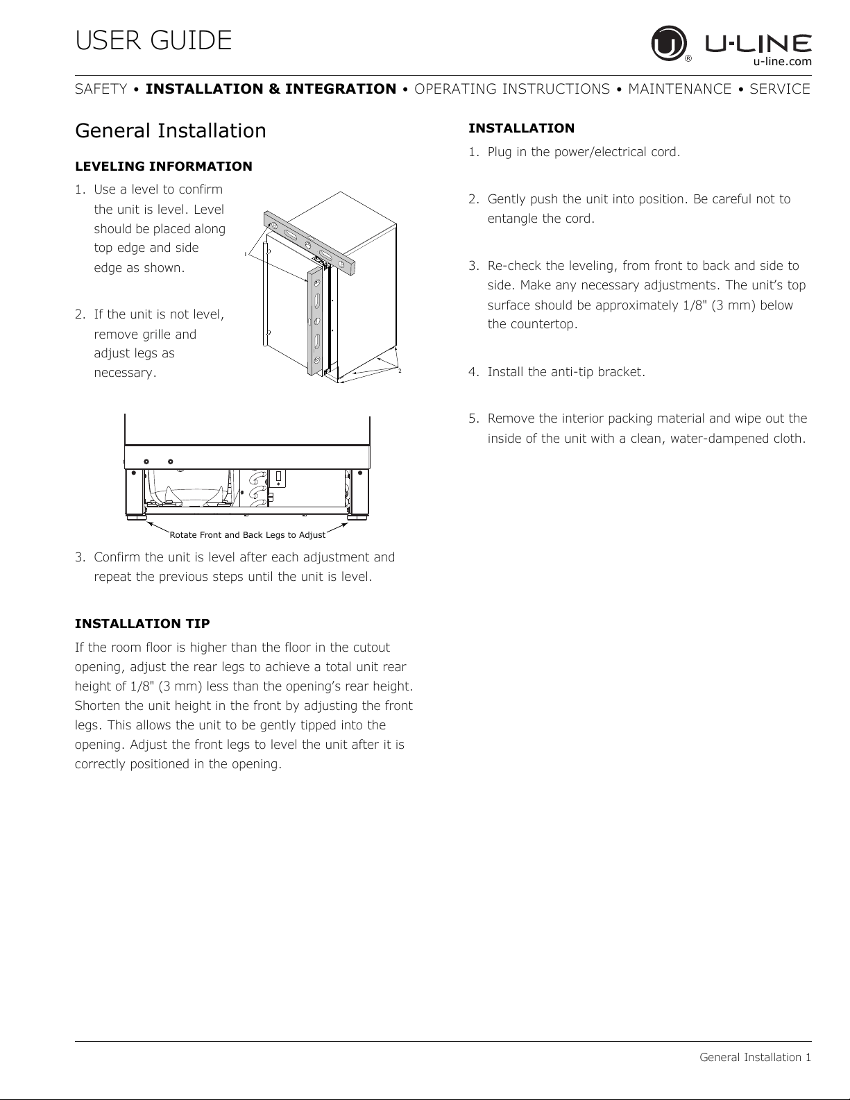
LEVELING INFORMATION
1. Use a level to confirm
the unit is level. Level
should be placed along
top edge and side
edge as shown.
2. If the unit is not level,
remove grille and
adjust legs as
necessary.
3. Confirm the unit is level after each adjustment and
repeat the previous steps until the unit is level.
INSTALLATION TIP
If the room floor is higher than the floor in the cutout
opening, adjust the rear legs to achieve a total unit rear
height of 1/8" (3 mm) less than the opening’s rear height.
Shorten the unit height in the front by adjusting the front
legs. This allows the unit to be gently tipped into the
opening. Adjust the front legs to level the unit after it is
correctly positioned in the opening.
INSTALLATION
1. Plug in the power/electrical cord.
2. Gently push the unit into position. Be careful not to
entangle the cord.
3. Re-check the leveling, from front to back and side to
side. Make any necessary adjustments. The unit’s top
surface should be approximately 1/8" (3 mm) below
the countertop.
4. Install the anti-tip bracket.
5. Remove the interior packing material and wipe out the
inside of the unit with a clean, water-dampened cloth.
2
1
Rotate Front and Back Legs to Adjust
USER GUIDE
Integrated Grille - Plinth Dimensions 1
u-line.com
SAFETY • INSTALLATION & INTEGRATION • OPERATING INSTRUCTIONS • MAINTENANCE • SERVICE
Integrated Grille - Plinth
Dimensions
PREPARE AND INSTALL INTEGRATED GRILLE
(PLINTH STRIP/BASE FASCIA)
1. Use the dimensions provided in the diagram to cut and
shape your integrated grille (plinth strip/base fascia)
panel. Recommended panel thickness is between 1/4"
(6 mm) and 3/8" (9 mm).
2. Finish or stain your grille (plinth strip/base fascia)
panel to match your surrounding furniture. Finish
front, back and edges to prevent warping. Carefully
follow the manufacturer’s recommendations for finish
application and cure times.
3. Apply double sided tape to the backside of the
integrated grill (plinth strip/base fascia). Use the
diagram below for reference. U-Line recommends
3M
™ VHB™ tape, a high strength bonding tape.
4. Remove backing paper from double sided tape.
5. Carefully align grille (plinth strip/base fascia) over
integrated panel and press into position.
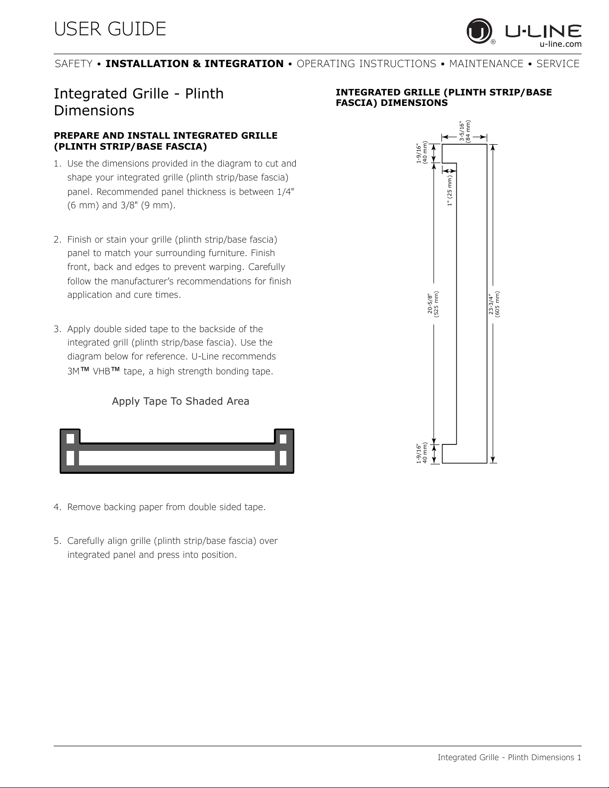
INTEGRATED GRILLE (PLINTH STRIP/BASE
FASCIA) DIMENSIONS
Apply Tape To Shaded Area
23-3/4"
(605 mm)
20-5/8"
(525 mm)
1-9/16"
40 mm)
1-9/16"
(40 mm)
1" (25 mm)
3-5/16"
(84 mm)
USER GUIDE
Grille - Plinth Installation 1
u-line.com
SAFETY • INSTALLATION & INTEGRATION • OPERATING INSTRUCTIONS • MAINTENANCE • SERVICE
Grille - Plinth Installation
REMOVING AND INSTALLING GRILLE
(PLINTH STRIP/BASE FASCIA)
WARNING
!
Disconnect electric power to the unit before
removing the grille (plinth strip/base fascia).
When using the unit, the grille (plinth strip/base
fascia) must be installed.
WARNING
!
DO NOT touch the condenser fins. The condenser
fins are SHARP and can be easily damaged.
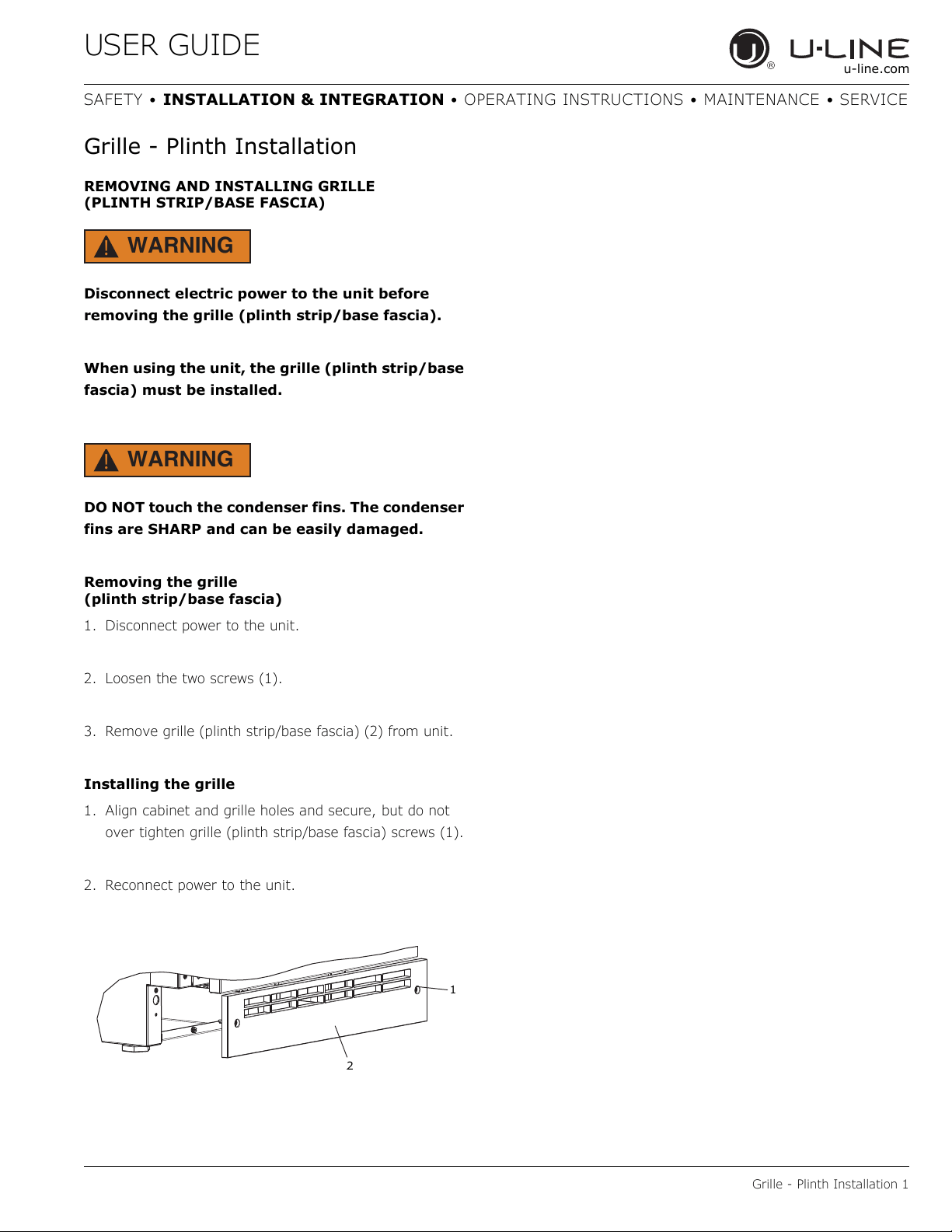
Removing the grille
(plinth strip/base fascia)
1. Disconnect power to the unit.
2. Loosen the two screws (1).
3. Remove grille (plinth strip/base fascia) (2) from unit.
Installing the grille
1. Align cabinet and grille holes and secure, but do not
over tighten grille (plinth strip/base fascia) screws (1).
2. Reconnect power to the unit.
1
2
USER GUIDE
Door Swing 1
u-line.com
SAFETY • INSTALLATION & INTEGRATION • OPERATING INSTRUCTIONS • MAINTENANCE • SERVICE
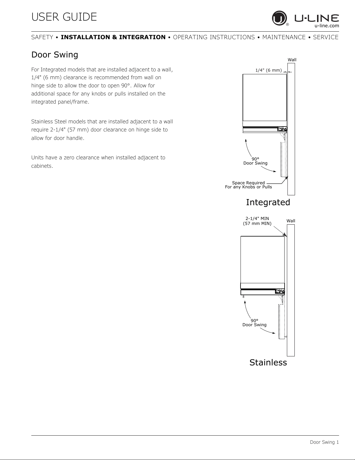
Door Swing
For Integrated models that are installed adjacent to a wall,
1/4" (6 mm) clearance is recommended from wall on
hinge side to allow the door to open 90°. Allow for
additional space for any knobs or pulls installed on the
integrated panel/frame.
Stainless Steel models that are installed adjacent to a wall
require 2-1/4" (57 mm) door clearance on hinge side to
allow for door handle.
Units have a zero clearance when installed adjacent to
cabinets.
Wall
Wall
90°
Door Swing
90°
Door Swing
Space Required
For any Knobs or Pulls
2-1/4" MIN
(57 mm MIN)
Integrated
Stainless
1/4" (6 mm)
USER GUIDE
Door Stop 1
u-line.com
SAFETY • INSTALLATION & INTEGRATION • OPERATING INSTRUCTIONS • MAINTENANCE • SERVICE
Door Stop
Your U-Line unit was shipped to you with the optional 90°
pin.
Your unit’s door(s) will open 115° straight from the
factory. If you would like the door stop at 90° follow these
instructions.
NOTICE
If your unit is already undercounter, it will need
to be moved out to access the hinge. With the
90° stop pin in place, you will not be able to
replace the hinge cover.
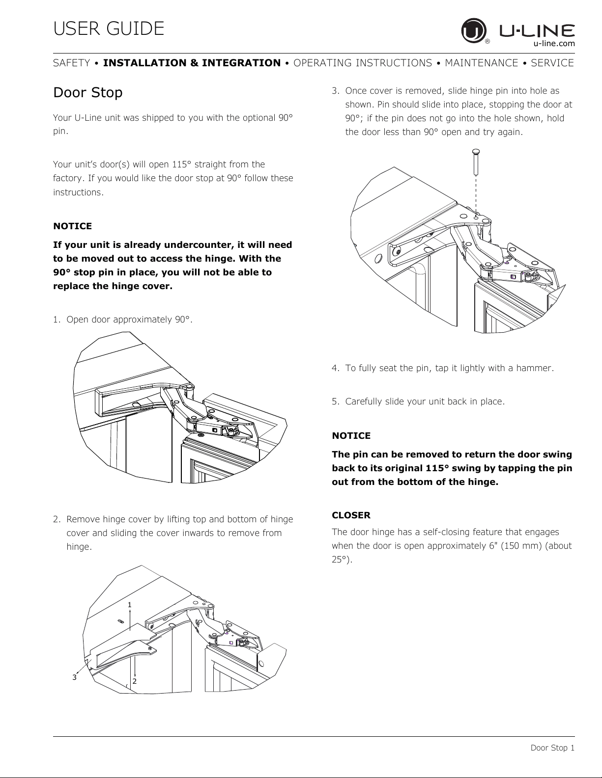
1. Open door approximately 90°.
2. Remove hinge cover by lifting top and bottom of hinge
cover and sliding the cover inwards to remove from
hinge.
3. Once cover is removed, slide hinge pin into hole as
shown. Pin should slide into place, stopping the door at
90°; if the pin does not go into the hole shown, hold
the door less than 90° open and try again.
4. To fully seat the pin, tap it lightly with a hammer.
5. Carefully slide your unit back in place.
NOTICE
The pin can be removed to return the door swing
back to its original 115° swing by tapping the pin
out from the bottom of the hinge.
CLOSER
The door hinge has a self-closing feature that engages
when the door is open approximately 6" (150 mm) (about
25°).
1
3
2
USER GUIDE
Door Adjustments 1
u-line.com
SAFETY • INSTALLATION & INTEGRATION • OPERATING INSTRUCTIONS • MAINTENANCE • SERVICE
Door Adjustments
DOOR ALIGNMENT AND ADJUSTMENT
Align and adjust the door if it is not level or is not sealing
properly. If the door is not sealed, the unit may not cool
properly, or excessive frost or condensation may form in
the interior.
NOTICE
Properly aligned, the door’s gasket should be
firmly in contact with the cabinet all the way
around the door (no gaps). Carefully examine
the door’s gasket to ensure that it is firmly in
contact with the cabinet. Also make sure the
door gasket is not pinched on the hinge side of
the door.
CAUTION
!
Do not attempt to use the door to raise or pivot
your unit. This would put excessive stress on the
hinge system.
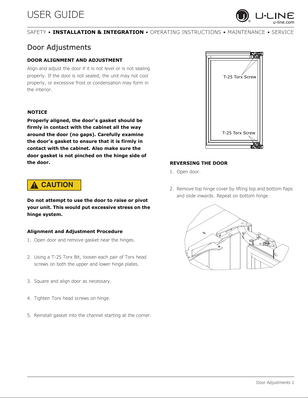
Alignment and Adjustment Procedure
1. Open door and remove gasket near the hinges.
2. Using a T-25 Torx Bit, loosen each pair of Torx head
screws on both the upper and lower hinge plates.
3. Square and align door as necessary.
4. Tighten Torx head screws on hinge.
5. Reinstall gasket into the channel starting at the corner.
REVERSING THE DOOR
1. Open door.
2. Remove top hinge cover by lifting top and bottom flaps
and slide inwards. Repeat on bottom hinge.
T-25 Torx Screw
T-25 Torx Screw
Door Adjustments 2
USER GUIDE
SAFETY • INSTALLATION & INTEGRATION • OPERATING INSTRUCTIONS • MAINTENANCE • SERVICE
u-line.com
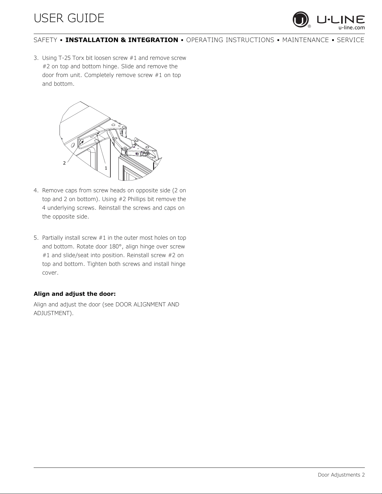
3. Using T-25 Torx bit loosen screw #1 and remove screw
#2 on top and bottom hinge. Slide and remove the
door from unit. Completely remove screw #1 on top
and bottom.
4. Remove caps from screw heads on opposite side (2 on
top and 2 on bottom). Using #2 Phillips bit remove the
4 underlying screws. Reinstall the screws and caps on
the opposite side.
5. Partially install screw #1 in the outer most holes on top
and bottom. Rotate door 180°, align hinge over screw
#1 and slide/seat into position. Reinstall screw #2 on
top and bottom. Tighten both screws and install hinge
cover.
Align and adjust the door:
Align and adjust the door (see DOOR ALIGNMENT AND
ADJUSTMENT).
2
1
USER GUIDE
First Use 1
u-line.com
SAFETY • INSTALLATION & INTEGRATION • OPERATING INSTRUCTIONS • MAINTENANCE • SERVICE
First Use
All U-Line controls are preset at the factory. Initial startup
requires no adjustments.
NOTICE
U-Line recommends allowing the unit to run
overnight before loading with product.
When plugged in, the unit will begin operating under the
factory default settings. If the unit was turned off during
installation, simply press and the unit will immediately
switch on. To turn the unit off, press .
USER GUIDE
Control Operation 1
u-line.com
SAFETY • INSTALLATION & INTEGRATION • OPERATING INSTRUCTIONS • MAINTENANCE • SERVICE
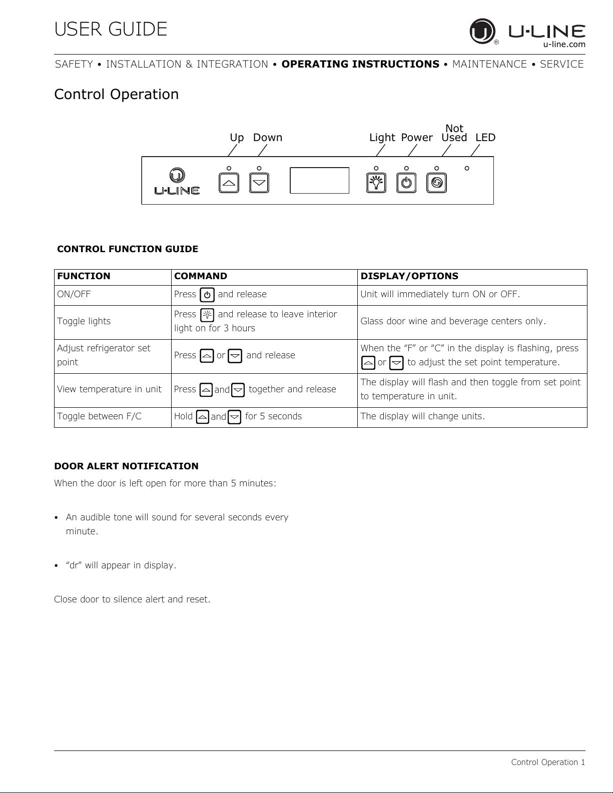
Control Operation
DOOR ALERT NOTIFICATION
When the door is left open for more than 5 minutes:
• An audible tone will sound for several seconds every
minute.
• “dr” will appear in display.
Close door to silence alert and reset.
Up Down Light Power
Not
Used LED
CONTROL FUNCTION GUIDE
FUNCTION COMMAND DISPLAY/OPTIONS
ON/OFF Press and release Unit will immediately turn ON or OFF.
Toggle lights
Press and release to leave interior
light on for 3 hours
Glass door wine and beverage centers only.
Adjust refrigerator set
point
Press and release
When the “F” or “C” in the display is flashing, press
to adjust the set point temperature.
View temperature in unit Press together and release
The display will flash and then toggle from set point
to temperature in unit.
Toggle between F/C Hold for 5 seconds The display will change units.
or
or
and
and
USER GUIDE
Sabbath Mode 1
u-line.com
SAFETY • INSTALLATION & INTEGRATION • OPERATING INSTRUCTIONS • MAINTENANCE • SERVICE
L
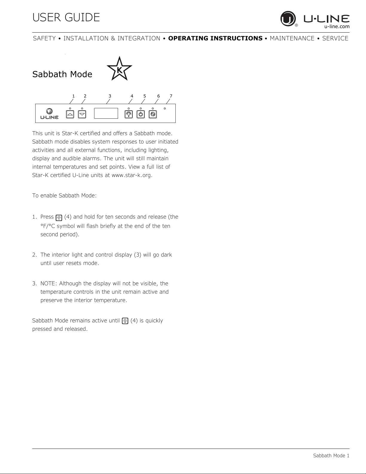
Sabbath Mode
This unit is Star-K certified and offers a Sabbath mode.
Sabbath mode disables system responses to user initiated
activities and all external functions, including lighting,
display and audible alarms. The unit will still maintain
internal temperatures and set points. View a full list of
Star-K certified U-Line units at www.star-k.org.
To enable Sabbath Mode:
1. Press (4) and hold for ten seconds and release (the
°F/°C symbol will flash briefly at the end of the ten
second period).
2. The interior light and control display (3) will go dark
until user resets mode.
3. NOTE: Although the display will not be visible, the
temperature controls in the unit remain active and
preserve the interior temperature.
Sabbath Mode remains active until (4) is quickly
pressed and released.
12 3456 7
USER GUIDE
Airflow and Product Loading 1
u-line.com
SAFETY • INSTALLATION & INTEGRATION • OPERATING INSTRUCTIONS • MAINTENANCE • SERVICE
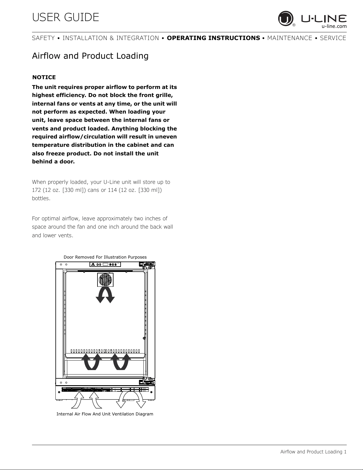
Airflow and Product Loading
NOTICE
The unit requires proper airflow to perform at its
highest efficiency. Do not block the front grille,
internal fans or vents at any time, or the unit will
not perform as expected. When loading your
unit, leave space between the internal fans or
vents and product loaded. Anything blocking the
required airflow/circulation will result in uneven
temperature distribution in the cabinet and can
also freeze product. Do not install the unit
behind a door.
When properly loaded, your U-Line unit will store up to
172 (12 oz. [330 ml]) cans or 114 (12 oz. [330 ml])
bottles.
For optimal airflow, leave approximately two inches of
space around the fan and one inch around the back wall
and lower vents.
Door Removed For Illustration Purposes
Internal Air Flow And Unit Ventilation Diagram
USER GUIDE
Interior Shelves 1
u-line.com
SAFETY • INSTALLATION & INTEGRATION • OPERATING INSTRUCTIONS • MAINTENANCE • SERVICE
Interior Shelves
REMOVING AND INSTALLING GLASS SHELVES
Adjusting Interior Shelves
Models equipped with glass shelves have an adjustable
mounting system. To adjust or simply remove shelves for
cleaning, follow the instructions below.
1. Remove all product from shelf.
2. Coming from underneath the shelf, lift both the front
and rear of the glass.
3. Carefully slide shelf out of unit being careful not to
scratch the interior liner.
4. Installation is the reverse of removal.
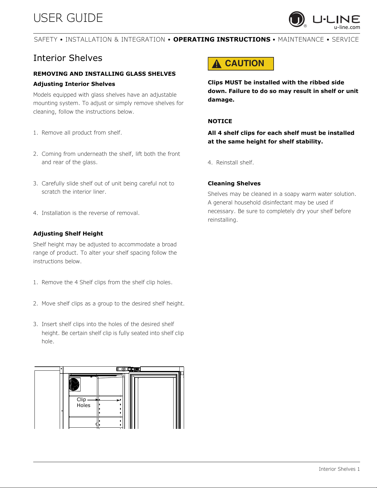
Adjusting Shelf Height
Shelf height may be adjusted to accommodate a broad
range of product. To alter your shelf spacing follow the
instructions below.
1. Remove the 4 Shelf clips from the shelf clip holes.
2. Move shelf clips as a group to the desired shelf height.
3. Insert shelf clips into the holes of the desired shelf
height. Be certain shelf clip is fully seated into shelf clip
hole.
CAUTION
!
Clips MUST be installed with the ribbed side
down. Failure to do so may result in shelf or unit
damage.
NOTICE
All 4 shelf clips for each shelf must be installed
at the same height for shelf stability.
4. Reinstall shelf.
Cleaning Shelves
Shelves may be cleaned in a soapy warm water solution.
A general household disinfectant may be used if
necessary. Be sure to completely dry your shelf before
reinstalling.
Clip
Holes
USER GUIDE
Refrigerator Bins - Crisper 1
u-line.com
SAFETY • INSTALLATION & INTEGRATION • OPERATING INSTRUCTIONS • MAINTENANCE • SERVICE
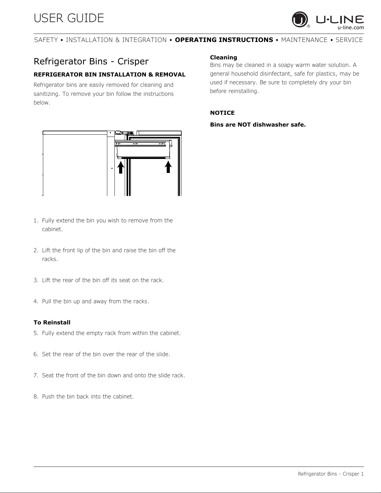
Refrigerator Bins - Crisper
REFRIGERATOR BIN INSTALLATION & REMOVAL
Refrigerator bins are easily removed for cleaning and
sanitizing. To remove your bin follow the instructions
below.
1. Fully extend the bin you wish to remove from the
cabinet.
2. Lift the front lip of the bin and raise the bin off the
racks.
3. Lift the rear of the bin off its seat on the rack.
4. Pull the bin up and away from the racks.
To Reinstall
5. Fully extend the empty rack from within the cabinet.
6. Set the rear of the bin over the rear of the slide.
7. Seat the front of the bin down and onto the slide rack.
8. Push the bin back into the cabinet.
Cleaning
Bins may be cleaned in a soapy warm water solution. A
general household disinfectant, safe for plastics, may be
used if necessary. Be sure to completely dry your bin
before reinstalling.
NOTICE
Bins are NOT dishwasher safe.
USER GUIDE
Cleaning 1
u-line.com
SAFETY • INSTALLATION & INTEGRATION • OPERATING INSTRUCTIONS • MAINTENANCE • SERVICE
Cleaning
EXTERIOR CLEANING
Stainless Models
Stainless door panels and handles can discolor when
exposed to chlorine gas, pool chemicals, saltwater or
cleaners with bleach.
Keep your stainless unit looking new by cleaning with a
good quality all-in-one stainless steel cleaner and polish
monthly. For best results use Claire
®
Stainless Steel
Polish and Cleaner. Comparable products are acceptable.
Frequent cleaning will remove surface contamination that
could lead to rust. Some installations may require cleaning
weekly.
Do not clean with steel wool pads.
Do not use stainless steel cleaners or polishes on
any glass surfaces.
Clean any glass surfaces with a non-chlorine glass
cleaner.
Do not use cleaners not specifically intended for
stainless steel on stainless steel surfaces (this
includes glass, tile and counter cleaners).
If any surface discoloring or rusting appears, clean it
quickly with Bon-Ami
®
or Barkeepers Friend Cleanser
®
and a nonabrasive cloth. Always clean with the grain.
Always finish with Claire
®
Stainless Steel Polish and
Cleaner or comparable product to prevent further
problems.
Using abrasive pads such as Scotchbrite™ will
cause the graining in the stainless steel to
become blurred.
Rust not cleaned up promptly can penetrate the
surface of the stainless steel and complete
removal of the rust may not be possible.
Integrated Models
To clean integrated panels, use household cleaner per the
cabinet manufacturer’s recommendation.
INTERIOR CLEANING
Disconnect power to the unit.
Clean the interior and all removed components using a
mild nonabrasive detergent and warm water solution
applied with a soft sponge or non-abrasive cloth.
Rinse the interior using a soft sponge and clean water.
Do not use any solvent-based or abrasive
cleaners. These types of cleaners may transfer taste to
the interior products and damage or discolor the lining.
DEFROSTING
Under normal conditions this unit does not require manual
defrosting. Minor frost on the rear wall or visible through
the evaporator plate vents is normal and will melt during
each off cycle.
If there is excessive build-up of 1/4" (6 mm) or more,
manually defrost the unit.
Ensure the door is closing and sealing properly.
High ambient temperature and excessive humidity can
also produce frost.
CAUTION
!
DO NOT use an ice pick or other sharp
instrument to help speed up defrosting. These
instruments can puncture the inner lining or
damage the cooling unit. DO NOT use any type of
heater to defrost. Using a heater to speed up
defrosting can cause personal injury and
damage to the inner lining.
USER GUIDE
Cleaning 2
u-line.com
SAFETY • INSTALLATION & INTEGRATION • OPERATING INSTRUCTIONS • MAINTENANCE • SERVICE
NOTICE
The drain pan was not designed to capture the
water created when manually defrosting. To
prevent water from overflowing the drain pan
and possibly damaging water sensitive flooring,
the unit must be removed from cabinetry.
To defrost:
1. Disconnect power to the unit.
2. Remove all products from the interior.
3. Prop the door in an open position (2 in. [50 mm]
minimum).
4. Allow the frost to melt naturally.
5. After the frost melts completely clean the interior and
all removed components. (See INTERIOR CLEANING).
6. When the interior is dry, reconnect power and turn unit
on.
USER GUIDE
Cleaning Condenser 1
u-line.com
SAFETY • INSTALLATION & INTEGRATION • OPERATING INSTRUCTIONS • MAINTENANCE • SERVICE
Cleaning Condenser
INTERVAL - EVERY SIX MONTHS
To maintain operational efficiency, keep the front grille
(plinth strip/base fascia) free of dust and lint, and clean
the condenser when necessary. Depending on
environmental conditions, more or less frequent cleaning
may be necessary.
WARNING
!
Disconnect electric current to the unit before
cleaning the condenser.
NOTICE
DO NOT use any type of cleaner on the
condenser unit. Condenser may be cleaned using
a vacuum, soft brush or compressed air.
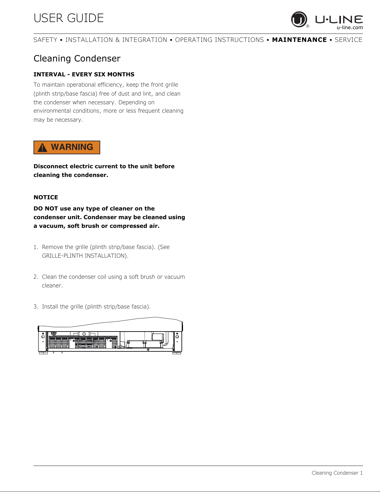
1. Remove the grille (plinth strip/base fascia). (See
GRILLE-PLINTH INSTALLATION).
2. Clean the condenser coil using a soft brush or vacuum
cleaner.
3. Install the grille (plinth strip/base fascia).
USER GUIDE
Extended Non-Use 1
u-line.com
SAFETY • INSTALLATION & INTEGRATION • OPERATING INSTRUCTIONS • MAINTENANCE • SERVICE
Extended Non-Use
VACATION/HOLIDAY, PROLONGED SHUTDOWN
The following steps are recommended for periods of
extended non-use:
1. Remove all consumable content from the unit.
2. Disconnect the power cord from its outlet/socket and
leave it disconnected until the unit is returned to
service.
3. If ice is on the evaporator, allow ice to thaw naturally.
4. Clean and dry the interior of the unit. Ensure all water
has been removed from the unit.
5. The door must remain open to prevent formation of
mold and mildew. Open door a minimum of 2"
(50 mm) to provide the necessary ventilation.
WINTERIZATION
If the unit will be exposed to temperatures of 40°F (5°C)
or less, the steps above must be followed.
For questions regarding winterization, please
call U-Line at +1.800.779.2547.
CAUTION
!
Damage caused by freezing temperatures is not
covered by the warranty.
USER GUIDE
Troubleshooting 1
u-line.com
SAFETY • INSTALLATION & INTEGRATION • OPERATING INSTRUCTIONS • MAINTENANCE • SERVICE
Troubleshooting
BEFORE CALLING FOR SERVICE
If you think your U-Line product is malfunctioning, read
the CONTROL OPERATION section to clearly understand
the function of the control.
If the problem persists, read the NORMAL OPERATING
SOUNDS and TROUBLESHOOTING GUIDE sections below
to help you quickly identify common problems and
possible causes and remedies. Most often, this will resolve
the problem without the need to call for service.
IF SERVICE IS REQUIRED
If you do not understand a troubleshooting remedy, or
your product needs service, contact U-Line Corporation
directly at +1.800.779.2547.
When you call, you will need your product Model and
Serial Numbers. This information appears on the Model
and Serial number plate located on the upper right or rear
wall of the interior of your product.
NORMAL OPERATING SOUNDS
All models incorporate rigid foam insulated cabinets to
provide high thermal efficiency and maximum sound
reduction for its internal working components. Despite this
technology, your model may make sounds that are
unfamiliar.
Normal operating sounds may be more noticeable because
of the unit’s environment. Hard surfaces such as cabinets,
wood, vinyl or tiled floors and paneled walls have a
tendency to reflect normal appliance operating noises.
Listed below are common refrigeration components with a
brief description of the normal operating sounds they
make. NOTE: Your product may not contain all the
components listed.
• Compressor: The compressor makes a hum or pulsing
sound that may be heard when it operates.
• Evaporator: Refrigerant flowing through an evaporator
may sound like boiling liquid.
• Condenser Fan: Air moving through a condenser may
be heard.
• Automatic Defrost Drain Pan: Water may be heard
dripping or running into the drain pan when the unit is
in the defrost cycle.
TROUBLESHOOTING GUIDE
DANGER
!
ELECTROCUTION HAZARD. Never attempt to
repair or perform maintenance on the unit
before disconnecting the main electrical power.
Troubleshooting - What to check when problems occur:
Problem Possible Cause and Remedy
Digital Display
and Light Do Not
Work.
Ensure power is connected to the unit.
If the unit is cooling, it may be in Sabbath
mode.
Interior Light
Does Not
Illuminate.
The light bulb may be defective.
If the unit is cooling, it may be in Sabbath
mode.
Light Remains on
When Door Is
Closed.
For glass door models, press the light icon
and close the door.
Check reed switch.
Unit Develops
Frost on Internal
Surfaces.
Frost on the rear wall is normal and will melt
during each off cycle.
If there is excessive build-up of 1/4" or
more, manually defrost the unit.
Ensure the door is closing and sealing
properly.
High ambient temperature and excessive
humidity can also produce frost.
Unit Develops
Condensation on
External
Surfaces.
The unit is exposed to excessive humidity.
Moisture will dissipate as humidity levels
decrease.
Digital Display
Functions, But
Unit Does Not
Cool.
Ensure the unit is not in “Showroom Mode.”
Momentarily unplug or interrupt power
supply to the unit.
Digital Display
Shows ER or E
Followed by a
Number.
E3 indicates the door may be opened too
long. Ensure the door is closing properly.
For other error codes contact U-Line
Customer Service.
USER GUIDE
Troubleshooting 2
u-line.com
SAFETY • INSTALLATION & INTEGRATION • OPERATING INSTRUCTIONS • MAINTENANCE • SERVICE
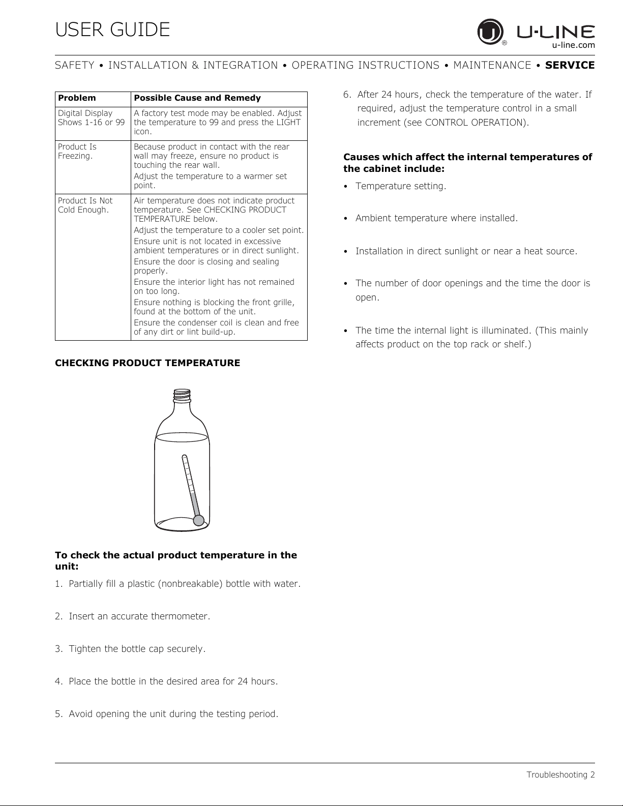
CHECKING PRODUCT TEMPERATURE
To check the actual product temperature in the
unit:
1. Partially fill a plastic (nonbreakable) bottle with water.
2. Insert an accurate thermometer.
3. Tighten the bottle cap securely.
4. Place the bottle in the desired area for 24 hours.
5. Avoid opening the unit during the testing period.
6. After 24 hours, check the temperature of the water. If
required, adjust the temperature control in a small
increment (see CONTROL OPERATION).
Causes which affect the internal temperatures of
the cabinet include:
• Temperature setting.
• Ambient temperature where installed.
• Installation in direct sunlight or near a heat source.
• The number of door openings and the time the door is
open.
• The time the internal light is illuminated. (This mainly
affects product on the top rack or shelf.)
Digital Display
Shows 1-16 or 99
A factory test mode may be enabled. Adjust
the temperature to 99 and press the LIGHT
icon.
Product Is
Freezing.
Because product in contact with the rear
wall may freeze, ensure no product is
touching the rear wall.
Adjust the temperature to a warmer set
point.
Product Is Not
Cold Enough.
Air temperature does not indicate product
temperature. See CHECKING PRODUCT
TEMPERATURE below.
Adjust the temperature to a cooler set point.
Ensure unit is not located in excessive
ambient temperatures or in direct sunlight.
Ensure the door is closing and sealing
properly.
Ensure the interior light has not remained
on too long.
Ensure nothing is blocking the front grille,
found at the bottom of the unit.
Ensure the condenser coil is clean and free
of any dirt or lint build-up.
Problem Possible Cause and Remedy
USER GUIDE
Warranty 1
u-line.com
SAFETY • INSTALLATION & INTEGRATION • OPERATING INSTRUCTIONS • MAINTENANCE • SERVICE
U-Line Corporation | Limited Warranty
1. U-Line Corporation (“U-Line”) warrants each U-Line
product to be free from defects in materials and
workmanship for a period of one year (two years on
Modular 3000 Series) from the date of installation. U-
Line further warrants the sealed system (consisting of
the compressor, condenser, evaporator, hot gas
bypass valve, dryer, and connecting tube) in each U-
Line product to be free from defects in materials and
workmanship for a period of five years from the date of
installation.
2. During the initial one year warranty period (two years
on Modular 3000 Series) for all U-Line products U-Line
shall: (1) repair any product or replace any part of a
product; and (2) for all Marine, RV and Domestic U-
Line products sold and serviced in the United States
(including Alaska and Hawaii) and Canada, U-Line shall
be responsible for the labor costs performed by a U-
Line authorized service company, incurred in
connection with the replacement of any defective part.
During years two through five of the warranty period
for the sealed system, U-Line shall: (1) at U-Line’s
option repair or replace any part of the sealed system;
and (2) for all Marine, RV and Domestic U-Line
products sold and serviced in the United States
(including Alaska and Hawaii) and Canada, U-Line shall
be responsible for the labor costs incurred in
connection with the replacement of any defective part
of the sealed system. All other charges, including
transportation charges for replacements under this
warranty and labor costs not specifically covered by
this warranty, shall be the responsibility of the
purchaser. This warranty extends only to the original
purchaser of the U-Line product. The Product
Registration Card included with the product should be
promptly completed by you and mailed back to U-Line
or you can register on-line at www.u-line.com
.
3. The warranty listed above does not apply to floor
display models. The warranty for these models shall be
one year from the date of installation. This one-year
warranty does not apply to cosmetic damages; proof of
purchase may be required.
4. The following conditions are excluded from this limited
warranty: use of cleaners other than the recommended
stainless steel cleaners and U-Line Clear Ice Maker
cleaner; installation charges; damages caused by
disasters or acts of God, such as fire, floods, wind and
lightning; damages incurred or resulting from shipping,
improper installation, unauthorized modification, or
misuse/abuse of the product; customer education
calls; food loss and spoilage; door and water level
adjustments (except during the first 30 days from the
date of installation); defrosting the product; adjusting
the controls; door reversal; and cleaning the
condenser.
5. U-Line products are designed to operate in ambient
temperatures between 50°F and 100°F unless
otherwise noted in the product manual. Exposure to
temperatures outside this range may cause
degradation of performance and issues such as lower
ice production or spoiled contents are not covered
under the terms of this warranty as a result of that
exposure. U-Line product may not be subjected to
temperatures below 40°F without following the
winterization and vacation shutdown procedures in
your product manual.
6. U-Line’s Outdoor Limited Warranty, set forth in this
Paragraph 6, shall apply to U-Line models deemed
suitable for outdoor use by Underwriters Laboratory
(“UL”) as noted in the U-Line Product Catalog, U-Line’s
website and/or on the serial tag located inside the
product. Outdoor product may come into contact with
rain by virtue of outdoor use. Exposure to other
sources of water shall also cause this warranty to be
void, including flooding of the area in proximity of the
unit greater than 1/8" deep in water, hurricanes,
splashing of pool water, or directing a spray from a
hose or similar device into and around the unit.
7. If a product defect is discovered during the applicable
warranty period, you must promptly notify U-Line at 1-
800-779-2547 or the dealer from whom you purchased
the product. In no event shall such notification be
received later than 30 days after the expiration of the
applicable warranty period. U-Line may require that
USER GUIDE
Warranty 2
u-line.com
SAFETY • INSTALLATION & INTEGRATION • OPERATING INSTRUCTIONS • MAINTENANCE • SERVICE
defective parts be returned, at your expense, to U-
Line’s factory in Milwaukee, Wisconsin, for inspection.
Any action by you for breach of warranty must be
commenced within one year after the applicable
warranty period.
8. THIS LIMITED WARRANTY IS IN LIEU OF ANY AND ALL
OTHER WARRANTIES, EXPRESS OR IMPLIED,
INCLUDING ANY IMPLIED WARRANTY OF
MERCHANTABILITY OR IMPLIED WARRANTY OF
FITNESS FOR A PARTICULAR PURPOSE, ALL OF WHICH
ARE DISCLAIMED. U-Line’s sole liability and your
exclusive remedy under this warranty are set forth in
the paragraphs above. U-Line shall have no liability
whatsoever for any incidental, consequential or special
damages arising from the sale, use or installation of
the product or from any other cause whatsoever
whether based on warranty (express or implied) or
otherwise based on contract, tort or any other theory
of liability.
9. Some states do not allow limitations on how long an
implied warranty lasts or the exclusion or limitation of
incidental or consequential damages, so the above
limitations may not apply to you. This warranty gives
you specific legal rights, and you may also have other
rights which vary from state to state.
10.Copyright © 2014 U-Line Corporation. All Rights
Reserved. | Publication Number 30379 | 03/2016 Rev. I