Loading ...
Loading ...
5
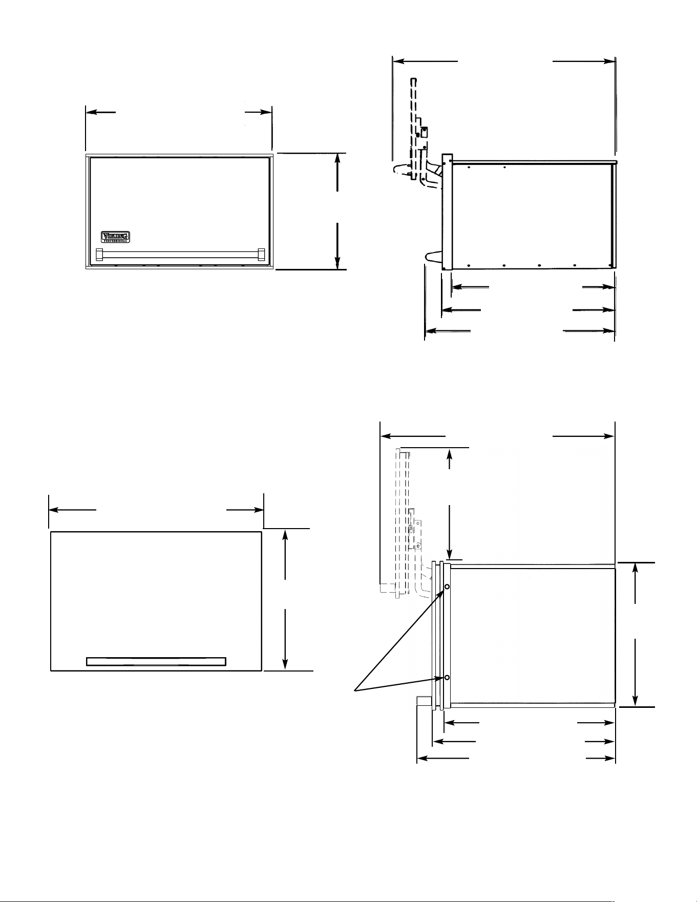
HINGE ADJUSTMENTS
(Professional and Designer Models)
To adjust the door up or down, loosen the retainer screws
and adjust the vertical adjustment screws to the desired
position. Retighten the retainer screws.
To adjust the door in or out, loosen the retainer screws
and adjust the horizontal adjustment screws to the desired
position. Retighten the retainer screws.
To adjust the pitch of the door and sides of the chamber,
loosen the retainer screws and adjust the pitch adjustment
screws to the desired position. Retighten the retainer
screws.
Pitch
Adjustment
Horizontal
Adjustment
Vertical
Adjustment
Retainer
Screws
USABLE SPACE INSIDE MULTI-USE CHAMBER
Two usable space options are given due to the location of the hinges for the upswing door. When using with a
microwave, allow adequate clearance for the opening of the microwave door. The chamber can also be used to store
cookbooks, small kitchen appliances, a television set, and other household items.
VMWC172 VMWC102 VMWC162
A B A B A B
Max. Height 12” (30.5 cm) 15” (38.1 cm) 12” (30.5 cm) 15” (38.1 cm) 12” (30.5 cm) 15” (38.1 cm)
Max. Width 23 5/8” (60.0 cm) 21” (53.3 cm) 26 5/8” (67.6 cm) 25” (63.5 cm) 32 5/8” (82.9 cm) 30” (76.2 cm)
Depth 22 1/2” (57.2 cm) 22 1/2” (57.2 cm) 22 1/2” (57.2 cm) 22 1/2” (57.2 cm) 22 1/2” (57.2 cm) 22 1/2” (57.2 cm)
DMWC171 DMWC101
A B A B
Max. Height 12 3/4” (32.4 cm) 15” (38.1 cm) 12 3/4” (32.4 cm) 15” (38.1 cm)
Max. Width 23 5/8” (60.0 cm) 22 3/4” (57.8 cm) 26 5/8” (67.6 cm) 25 3/4” (65.4 cm)
Depth 22 1/2” (57.2 cm) 22 1/2” (57.2 cm) 22 1/2” (57.2 cm) 22 1/2” (57.2 cm)
Option A
Option B
Hinge
Hinge
Hinge
Hinge
4
CABINET CUTOUT (Professional and Designer Models)
Recommended
Electrical Outlet
Location
18 5/8”
(47.3 cm)
10”
(25.4 cm)
24” min.
(61.0 cm)
A
(Professional Model Shown)
B
A B
VMWC172 25 1/4” (64.1 cm) 12 1/2” (31.7 cm)
VMWC102 28” (71.1 cm) 14” (35.5 cm)
VMWC162 33 3/4” (85.7 cm) 16 7/8” (42.9 cm)
DMWC171 25 1/4” (64.1 cm) 12 1/2” (31.7 cm)
DMWC101 28” (71.1 cm) 14” (35.5 cm)
CABINET MOUNTING -
(Professional and Designer Models)
Place the multi-use chamber in the cabinet cut-out.
Use the four enclosed screws to attach unit to the cabinet.
The adjustment brackets are used to adjust how far the
microwave slides back into the chamber.
Mounting screws
Adjustment
brackets
(Designer Model Shown)
Loading ...
Loading ...
Loading ...