Owners
Manual
FOR POTABLEWATER
HEATING ONLY
NOT SUITABLEFOR
SPACEHEATING
Model No.
153.324190 30 Gal.Short
153.324191 30 Gal.Short
153.324290 40 Gal.Short
153.324291 40 GaLShort
153.324390 30 Gal.
153.324391 30 Gal.
153.324490 40 Gal.
153.324491 40 Gal.
153.324690 HT 40 Gal. Medium
153.324691 HT 40 Gal. Medium
153.324792 50 Gal.
153.324793 50 Gal.
ENERGY EFFICIENTTN5
ELECTRIC
WATER HEATER
• Safety Instructions
• Installation
• Operation
• Care and Maintenance
• Troubleshooting
• Parts List
Caution:
Read and Follow
All Safety Rules and
Operating Instructions
Before First Use of
This Product.
Savethis Manual for Future Reference.
GAiVlA certification applies to all residential electric water heaters with
capacities of 20 to 120 Gallons. Input rating of 12 Kw or less at a voltage
no greater than 250 V,
I _WARNING
READ THE GENERAL SAFETY SECTION BEGINNING ON INSIDE COVER
AND THEN THIS ENTIRE MANUAL BEFORE INSTALLING OR OPERAT-
ING THIS WATER HEATER. i
Sears, Roebuck and Co., Hoffman Estates, IL 60179 U.S.A.
Safety Precautions
&WARNING . I
Improper installation, adjustment, alteration, service or I
maintenancecancauseDEATH, SERIOUS BODILY INJU.RY,I
OR PROPERTY DAMAGE. Refer to this manual for assm-I
.t_ce or.consultyourlocalSearsServiceCenter for furtherI
mforma_on. I
_,WARNING
At thetime ofmanufacturethiswaterheaterwasprovidedwith
a combinationtemperatu.re-pressuresrelief valvecertifiedbya
nationallyrecognizedtesting laboratorythat maintainsperiodic
inspectionof productionof listedequipmentor materials,as
meatingthe requirementsfor ReliefValvesandAutomaticGas
ShutoffDevicesfor Hot Water SupplySystems,andthe latest
edition of ANSI Z21,22andthe cederequirements of ASME.If
replaced,the valvemust meet the requirementsoflocalcedes,
but notlessthana combinationtemperature and pressurerelief
valvecertifiedasmeetingtile requirementsfor ReliefValvesand
AutomaticGasShutoffDevicesfor Hot Water SupplySystems,
ANSI Z21.22bya nationallyrecognizedtesting laboratorythat
maintainsperiedicinspectionof productionof listedequipment
ormaterials.
The valvemustbe markedwith a maximum set pressurenot
to exceedthe marked hydrostaticwort_ng pressureof the
water heater (150 Ibsdsq.in.) and a dischargecapacitynot
lessthan the water heater inputrate asshownon the model
rating plate.(Electricheaters- watts dividedby 1000x 3415
equaJBTU/Hr, rate.)
Yourlocaljurisdictionalauthority,whilemandatingtheuseof a
temperatumt)ressure relief valvecomplyingwith ANSI Z21,22
andASME,mayrequireavalvemodeldifferentfromtheonefur-
nishedwiththewater heater.
Compliancewith suchlocalrequirements mustbesatisfiedby
the installeror end userofthe water heaterwith a locallypre-
scribedtemperature-pressurerelief valveinstalledinthe desig-
natedopeningin the water heater in placeof the factoryfur-
nishedvalve.
Forsafeoperationof the water heater,the relief valvemustnot
beremovedfromit'sdesignatedopeningor plugged.
The temperature-pressurerelief valvemustbe installeddi_'tly
intotheErringofthewaterheaterdesignatedfor thereliefvalve.
Positionthevalvedownwardandprovidetubingsothat anydis-
chargewillexit onlywithin 6 inchesabove,or at anydistance
belowthe structuralfloor,Be certainthat no contactismade
withanyliveelectricalpart.The dischargeopeningmustnot be
blockedor reducedin sizeunderany circumstance_Excessive
length,over30 feet,or useofmore than fourelbowscancause
restrictionandreducethe dischargecapacityofthevalve.
No valveor otherobstro_on isto be placedbetweenthe relief
valveandthe tank. Do not connecttubing directlyto discharge
drainunlessa 6"air gapisprovided.Topreventbodilyinjury,haz-
ardto life,or pmpertydamage,the reliefvalvemustbeallowed
to dischargewaterin quantitiesshouldcircumstancesdemand.
If the dischargepipe is not connectedto a drain or other
suitable means, the water flow may cause property
damage.
The DischargePipe:
Mustnot be smallerin sizethan the outtet pipesizeofthe
valve,or haveanyreducingcouplingsor otherrestriction_
Mustnot be pluggedor Mucked.
Must be ofmateriallistedfor hot water distribution.
Must be installedsoasto allowcompletedrainageof both
the temperature-pressurereliefvalve, and the discharge
pipe.
Mustterminate at an adequatedrain.
Mustnot haveanyvalvebetween the relief valveand tank.
AWARNING
HAZARD OF ELECTRICAL SHOCKI Before removing I
any access panels or servicing the water heater, make I
sure the electrical supply to the water heater m turned
"OFF". Failure to do this could result in DEATH, SERI-
OUS BODILY INJUR_,OR PROPERTY DAMAGE.
AWARNING
HOTTER WATER CAN SCALD: Water heaters are
intended to produce hot water. Water heated to a tem-
perature whichwill satisfyspace.heating,clotheswashing,
dish washing, and other sanitizing needs can scald and
permanently injure you upon contact. Some people are
more likelyto be permanently injured by hot water than
others. These includethe elderly,children, the infirm, or
physically/mentally handicapped. If anyone using hot
water in your home fits into one of these groups or if
there isa local code or state law requiring a certain tem-
perature water at the hot water tap, then you must take
specialprecautions.In addition to usingthe lowest possi-
ble temperature setting that satisfies your hot water
needs,a means such as a mixing valve, shallbe used at
the hot water taps usedby these people or at the water
heater. Mixing valvesare availableat plumbingsupplyor
hardware stores. Follow manufacturers instructions for
installation of the valves. Before chang!ng the factory
setting on the thermostat, read the Temperature
Regulation"sectioninthis manual.
AWARNING
WATER HEATERS EQUIPPED FOR ONE VOLTAGE
ONLY: This water heater isequippedfor one type voltage
only.Check the rating plate near the bottom accesspanel
for the correct voltage. DO NOT usethis water heater
with any voltageother than the one shownon the model
rating plate. Failure to usethe correct voltagecan cause
problemswhich can result in DEATH, SERIOUS BODILY
INJURY,OR PROPERTY DAMAGE. If you haveany ques-
tions or doubtsconsultyour el_ric company.
AWARNING i
INSULATING !ACKETS: Whep installing an 1external
water heater insulation jacke_ o_ an electric water
heater: ! '
a. DO NOT cover the temperaturn-pressur_ relief Valve.
b. DO NOT put insulationover _he accesscoversor any
t ' i
access areas.
€. DO NOT cover or remove operatingiinst_'uctions, and
safety related warning labels_and:_materials affixed to
the water heater,
I _,WARNING
Do not usethis appl_ of it hasbeen under
water. An electrical short or malfunction couldoccur.The
water heater shouldbe replaced.
2
A CAUTION
WATER HEATERS EVENTUALLY LEAK: Installation of
the water heater must be accomplished in sucha manner
that ifthe tank or any connections shouldleak, the flow of
water will not cause damage to the structure. When such
locationscannot be avoided, a suitable drain pan should
be installedunder the water heater. Drain pans are avail-
able at your local SearsStore. Such a drain pan must be
piped to an adequate drain. Under no circumstances is
the manufacturer or Searsto be held liablefor anywater
damage in connection with thiswater heater,
Table of Contents
Safety Precautions ............................................................................................................................................2
Table of Contents .............................................................................................................................................3
Customer Responsibilities ...................................................................................................................4
Product Specincations ...............................................................................................................................4
Materials and Basic Tools Needed ..........................................................................................5
Materials Needed ...................................................................................................................................................................... 5
Basic Tools ................................................................................................................................................................................ 5
Installation Instructions ....................................................................................................................6-11
Removing the Old Water Heater ............................................................................................................................................... 6
Facts to Consider About the Location ....................................................................................................................................... 7
Water Piping ............................................................................................................................................................................. 8
Temperature-Pressure Relief Valve ............................................................................................................................................. 9
Filling the Water Heater .......................................................................................................................................................... 10
Wiring Diagram ................................................................................................................................... :................................. 10
Wiring .................................................................................................................................................................................... 11
Imtallation Checklist .............................................................................................................................................................. 12
Service and Adjustment ...................................................................................................................13-17
Temperature Regulation .......................................................................................................................................................... 13
Thermostats ............................................................................................................................................................................ 13
Temperature Settings .............................................................................................................................................................. 13
Thermostat Adjustment ..................................................................................................................................................... 13-14
Temperature-Pressure Relief Valve Operation .......................................................................................................................... 14
Draining ................................................................................................................................................................................. 14
Element Cleaning/Replacement ......................................................................................................................................... 15-17
Drain Valve Washer Replacement ........................................................................................................................................... 17
Service .................................................................................................................................................................................... 17
Troubleshooting Guide ....................................................................................................................18-21
Start Up Conditions ............................................................................................................................................................... 18
Thermal Expansion ............................................................................................................................................................... 18
Strange Sounds ..................................................................................................................................................................... 18
Operational Conditions ..................................................................................................................................................... 19-20
Smelly Water ......................................................................................................................................................................... 19
"Air" In Hot Water Faucets ................................................................................................................................................... 19
Rumbling Noise .................................................................................................................................................................... 19
High Temperature Shut Off System ................................................................................................................................. 19-20
Not Enough or No Hot Water .............................................................................................................................................. 20
Water Is Too Hot .................................................................................................................................................................. 20
Leakage Checkpoints .............................................................................................................................................................. 21
Parts Order List ............................................................................................................................................22-25
Warranty .......................................................................................................................................................................28
3
Customer Responsibilities
Thank You for purchasing a Sears water heater.
Properly installed and maintained, it should give you years of
trouble free service. If you should decide that you want the new
water heater professionally installed by Sears contact the local
Sears Service Center or any Sears store. They will arrange for
prompt, quality installation by Sears authorizedcontractors.
The installation must conform with the instructions in this
manual; electric company rules; and Local Codes, or in the
absence of Local Codes, with the latest edition of the
National Electrical Code. This publication is available from
your local government or public library or electric company
or by writing Underwriters Laboratories,333 Pfingsten Road,
Northbrook, IL 60062.
Abbreviations Found In This Instruction Manual
U.L.-Underwriters Laboratories, 333 Pfingsten Rd.,
Northbrook, IL 60062
National Electrical Code-This publication is available from your
local government or public library or electric company or by
writing to U.L. above.
A.N.S.I.-American National Standards Institute
• Read the "Safety Precautions" section, page 2 of this manual
first and then the entire manual carefully. If you don't follow
the safety rules, the water heater will not operate properly. It
could cause DEATH, SERIOUS BODILY INJURY
AND/OR PROPERTY DAMAGE.
This manual contains instructions for the installation, opera-
tion, and maintenance of this electric water heater. It also
contains warnings throughout the manual that you must read
and be awareof. All warnings and all instructions areessential
to the proper operation of the water heater and your safety.
Since we cannot put everything on the first few pages, READ
THIS ENTIRE MANUAL BEFORE ATTEMPTING TO
INSTALL OR OPERATE THE WATER HEATER.
• If after reading this manual you have any questions or do not
understand any portion of the instructions, call Sears Service
Center.
Carefully plan the place where you are going to put the water
heater. Correct electrical wiring and connections are very
important in preventing death from possible electrical shock
and fires.
Examine the location to ensure the water heater complies
with the _Factsto Consider About the Location"section.
For California installation this water heater must be braced,
anchored, or strapped to avoid falling or moving during an
earthquake. See instructions for correct installation proce-
dures. Instructions may be obtained from your local dealer,
wholesaler, public utilities or California Office of the State
Architect, 400 P Street, Sacramento, CA 95814.
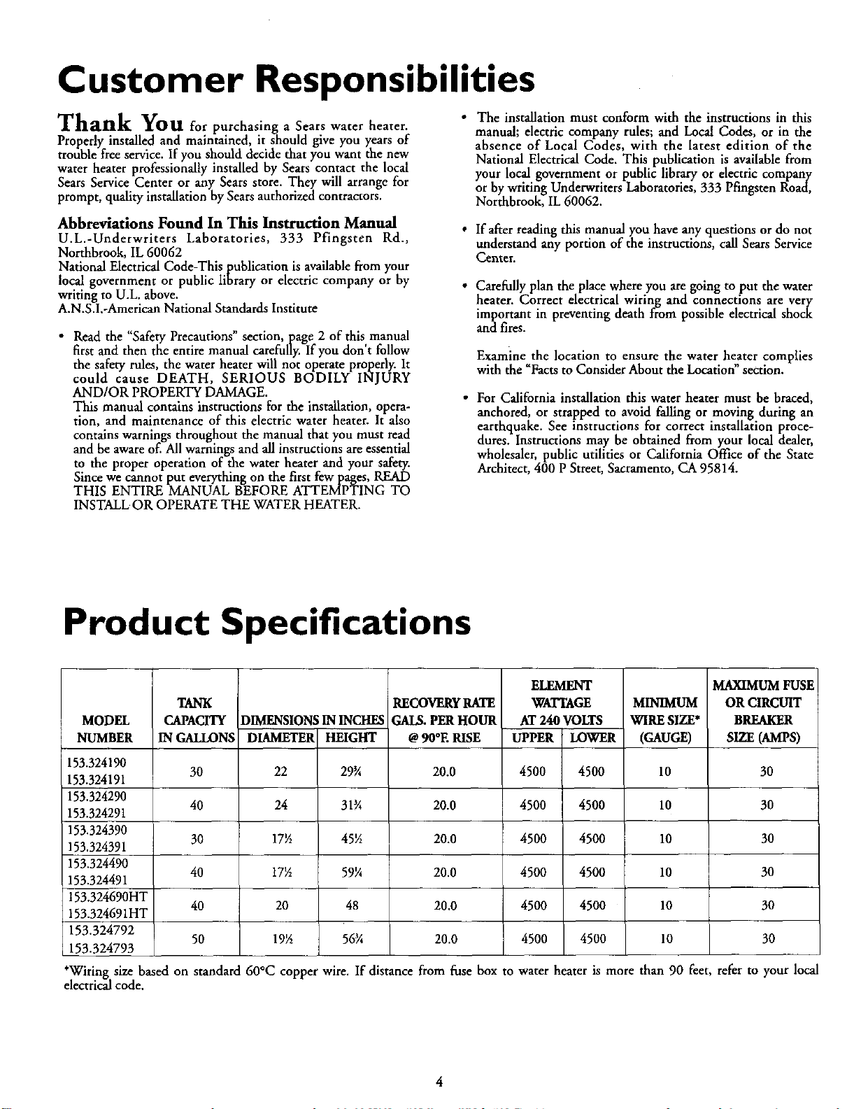
Product Specifications
MODEL
NUMBER
153.324190
153.324191
153.324290
153.324291
153.324390
153.324391
153.324490
153.324491
153.324690HT
153.324691HT
153.324792
153.324793
*Wiring size based
electrical code.
TANK
CAPACITY
IN GALLONS
30
40
30
40
40
50
DIMENSIONSININCHES
DIAMETER HEIGHT
22 29_
24 31_
17½ 45_
17½ 59½
20 48
19_ 56¾
RECOVERY RATE
GAI_. PER HOUR
@ 90°E RISE
20.0
20.0
20.0
20.0
20.0
20.0
ELEMENT
WATTAGE
AT 240 VOLTS
UPPER LOWER
4500 4500
4500 4500
4500 4500
4500 4500
4500 4500
4500 4500
MAXIMUM FUSE
MINIMUM
WIRE SIZE*
(GAUGE)
10
10
10
10
10
10
OR CIRCUIT
BREAKER
SIZE(AMPS)
30
30
30
30
30
3O
on standard 60°C copper wire. If distance from fuse box to water heater is more than 90 feet, refer to your local
Materials and Basic Tools Needed
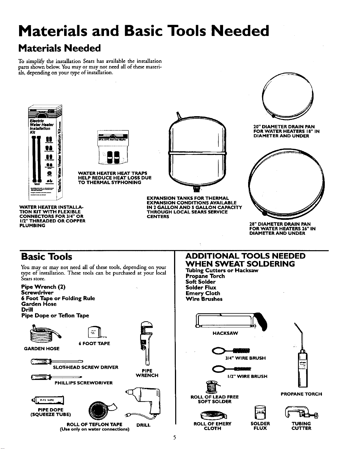
Materials Needed
To simplify the installation Sears has available the installation
parts shown below. You may or may not need all of these materi-
als, depending on your type of installation.
L
WaterHeater
Installation
Kit
|l
sa
WATER HEATER INSTALLA-
TION KIT WITH FLEXIBLE
CONNECTORS FOR 314" OR
I/2" THREADED OR COPPER
PLUMBING
WATER HEATER HEAT TRAPS
HELP REDUCE HEAT LOSS DUE
TO THERMAL SYPHONING
EXPANSION TANKS FOR THERMAL
EXPANSION CONDITIONS AVAILABLE
IN 2 GALLON AND 5 GALLON CAPACITY
THROUGH LOCAL SEARS SERVICE
CENTERS
20" DIAMETER DRAIN PAN
FOR WATER HEATERS 18" IN
DIAMETER AND UNDER
28" DIAMETER DRAIN PAN
FOR WATER HEATERS 26" IN
DIAMETER AND UNDER
Basic Tools
You may or may not need all of these tools, depending on ycour
type of installation. These tools can be purchased at your local
Sears store.
Pipe Wrench (2)
Screwdriver
6 Foot Tape or Folding Rule
Garden Hose
Drill
Pipe Dope or Teflon Tape
6 FOOT TAPE
GARDEN HOSE
sLoT-HEAD SCREW DRIVER
PHILLIPS SCREWDRIVER
PIPE DOPE
(SQUEEZE TUBE)
WRENCH
ROLL OF TEFLON TAPE
(Use only on water connections)
DRILL
ADDITIONAL TOOLS NEEDED
WHEN SWEAT SOLDERING
Tubing Cutters or Hacksaw
Propane Torch
Soft Solder
Solder Flux
Emery Cloth
Wire Brushes
BRUSH
112"WIRE BRUSH
PROPANE TORCH
ROLL OF LEAD FREE
SOFT SOLDER
ROLL OF EMERY SOLDER TUBING
CLOTH FLUX CUTTER
Installation Instructions
Removing the Old Water
Heater
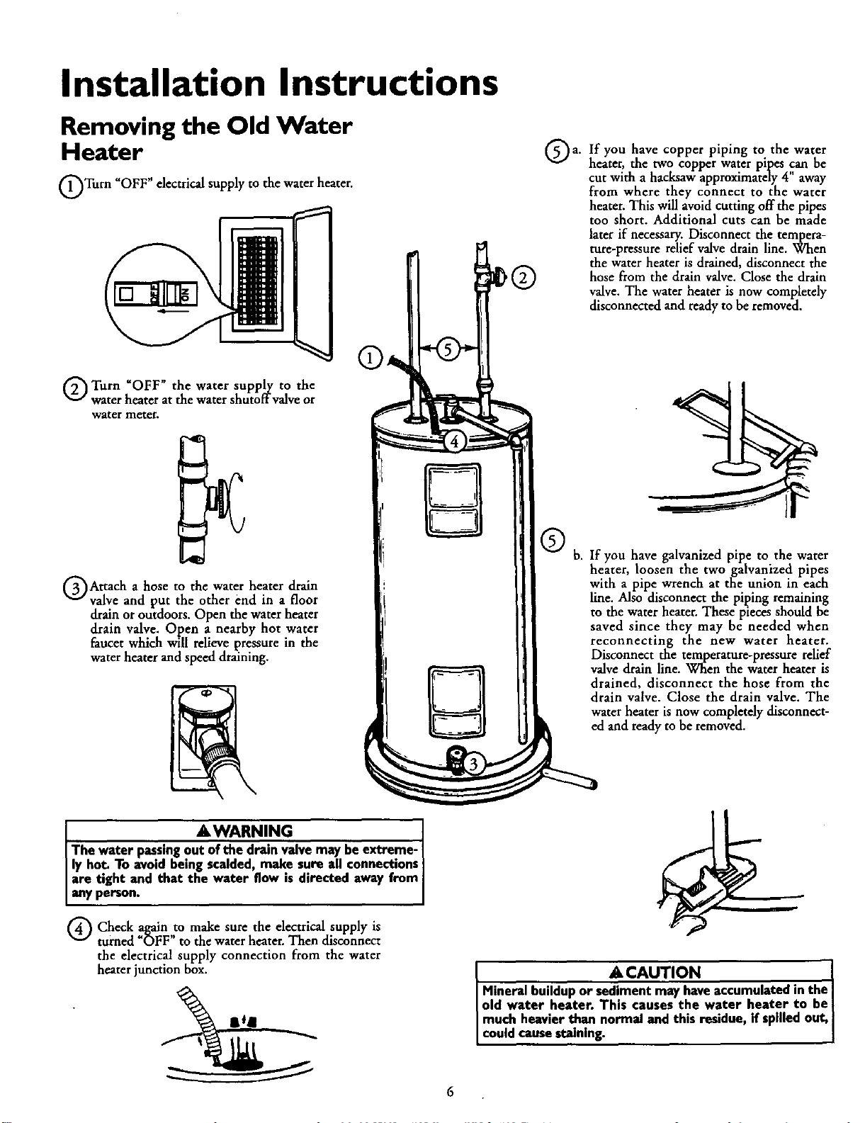
OTurn "OFF" electrical supply to the water heater.
Qa. If have piping to the water
you copper
heater, the two copper water pipes can be
cut with a hacksaw approximately 4" away
from where they connect to the water
heater. This will avoid cutting off the pipes
too short. Additional cuts can be made
later if necessary. Disconnect the tempera-
ture-pressure relief valve drain line. When
the water heater is drained, disconnect the
hose from the drain valve. Close the drain
valve. The water heater is now completely
disconnected and ready to be removed.
Q Turn _OFF" the water supply to the
water heater at the water shutoffvalve or
water meter.
GAttach a hose to the water heater drain
valve and put the other end in a floor
drain or outdoors. Open the water heater
drain valve. Open a nearby hot water
faucet which will relieve pressure in the
water heater and speed draining.
Q b. If you have galvanized pipe to the water
heater, loosen the two galvanized pipes
with a pipe wrench at the union in each
line. Also disconnect the piping remaining
to the water heater. These pieces should be
saved since they may be needed when
reconnecting the new water heater.
Disconnect the temperature-pressure relief
valve drain line. When the water heater is
drained, disconnect the hose from the
drain valve. Close the drain valve. The
fa_hreeaat_yitsOnbOw,oOmp_tdydisconnect-
AWARNING I
The water passingout of the dram valvemay beextreme- I
ly hot. To avoid being scalded,make sure all connectionsI
are tight and that the water flow is directed away from
any person.
Q Check again,to make sure the electrical supply is
turned _OFF to the water heater, Then disconnect
the electrical supply connection from the water
heater junction box.
6
ACAUTION "1
I Mineral buildupor sediment may haveaccumulated in the I
I old water heater. This causes the water heater to beI
I much heavier than normal and this residue, if spilledout,I
I could causestaining. I
Installation Instructions (cont'd)
Facts to Consider About
the Location
You should carefully choose an indoor location for the new
water heater, because the placement is a very important consid-
eration for the safety of the occupants in the building and for
the most economical use of the appliance. This water heater is
not intended for outdoor installation.
Whether replacing an old water heater or putting the water
heater in a new location, the following critical points must be
observed.
• The location selected should be indoors as close to and ascen-
tralized with the water pilling system as possible. This water
heater, as well as all water heaters, will eventually leak. Do not
install without adequate drainage provisions where water flow
will cause damage.
A, CAUTION
WATER HEATERS EVENTUALLY LEAK: Installation of
the water heater must be accomplishedin sucha manner
that if the tank or anyconnectionsshouldleak,the flow of
water will not causedamage to the structure. When such
locations cannot be avoided,a suitable drain pan should
be installedunder the water heater. Drain pansare avail-
able at your local Searsstores.Such a drain pan must be
piped to an adequate drain. Under no circumstances is
the manufacturer or Searsto he held liable for any water
damage in connectionwith this water heater.
I
A, CAUTION
INSTALLATION IN RESIDENTIAL GARAGES: The I
water heater must be located and/or protected so it is
not subjectto physca damage bya movng vehc e.
• The location selection must provide adequate clearances for
servicing and proper operation of the water heater.
Installation Instructions (cont'd)
Water Piping
AWARNING
HOTTER WATER CAN SCALD: Water heaters are
intended to produce hot water. Water heated to a tam-
perature which will satisfy spaceheating, clothes washing,
dish washing, and other sanitizing needs can scald and
permanently injure you upon contact, Some people are
more likely to be permanently mlured by hot water than
others. These include the elderly, children, the infirm, or
physically/mentally handicapped. If anyone using hot
water in your home fits into one of these groups or
there is a localcode or state law requiring a certain tam-
_eraeurewater at the hot water tap, then you must take
specialprecautions.In addition to usingthe lowest possi-
ble temperature setting that satisfies your hot water
needs, a means such as a mixing valve, shall be used at
the hot water taps used by these people or at the water
heater. Mixing valvesare availableat plumbing supplyor
hardware stores. Follow manufacturers instructions for
installationof the valves,Before changingthe factory set-
ting on the thermostat, read the "Temperature
Regulation" sectionin thismanual.
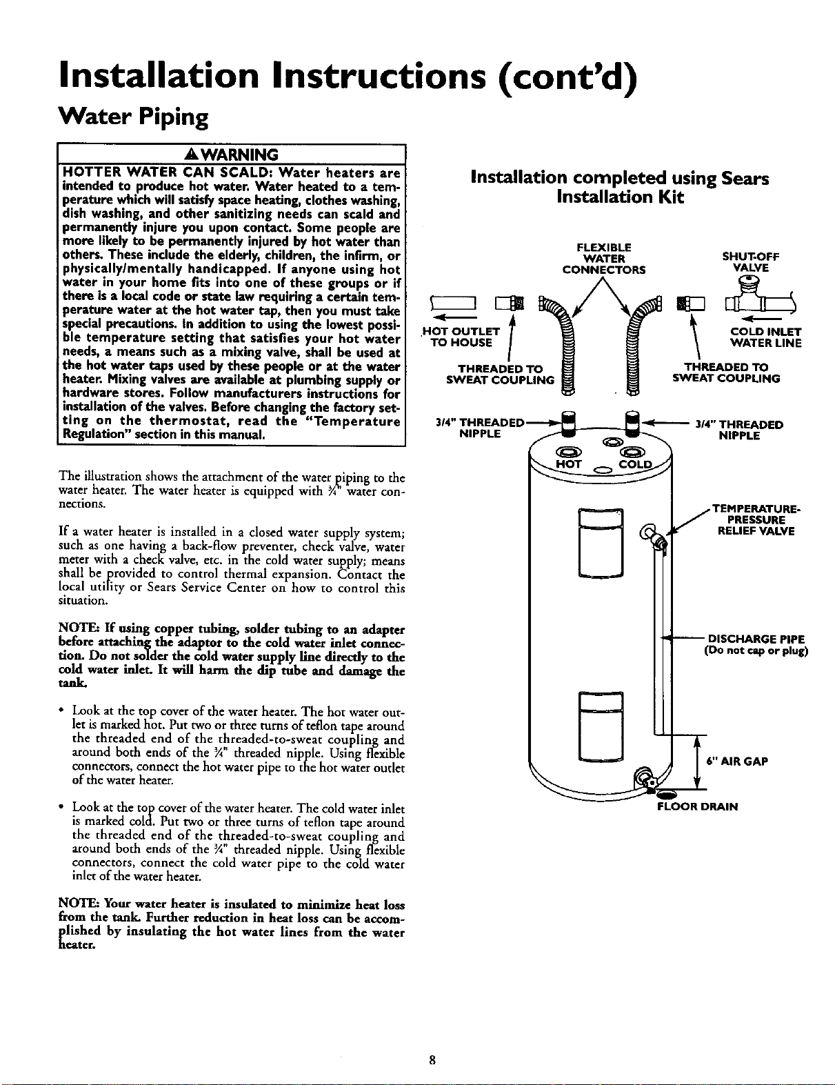
The illustration shows the attachment of the water [iping to the
water heater. The water heater is equipped with ¾ water con-
nections.
If a water heater is installed in a dosed water supply system;
such as one having a back-flow preventer, check valve, water
meter with a check valve, etc. in the cold water supply; means
shall be provided to control thermal expansion. Contact the
local utility or Sears Service Center on how to control this
situation.
NOTE: If using €opper tubing, solder tubing t.o an adapter
before attaching the adaptor to the cold water inlet connec-
tion. Do not so][derthe cold water supply line directly to the
cold water inlet. Is will harm the dip tube and damage the
tan_
• Look at the top cover of the water heater. The hot water out-
let is marked hot. Put two or three turns of teflon tape around
the threaded end of the threaded-to-sweat coupling and
around both ends of the % threaded nipple. Using flexible
connectors, connect the hot water pipe to the hot water outlet
of the water heater.
• Look at the top cover of the water heater. The cold water inlet
is marked cold. Put two or three turns of teflon tape around
the threaded end of the threaded-to-sweat coupling and
around both ends of the ¾ threaded nipple. Using[ flexible
connectors, connect the cold water pipe to the cold water
inlet of the water heater.
Installation completed using Sears
Installation Kit
FLEXIBLE
WATER SHUT*OFF
CONNECTORS VALVE
NOT OUTLET COLD INLET
• TO HOUSE WATER LINE
THREADED TO THREADED TO
SWEAT COUPLING SWEAT COUPLING
314" THREADED
NIPPLE NIPPLE
•TEMPERATURE-
PRESSURE
RELIEF VALVE
DISCHARGE PIPE
(Do not rap or plug)
S" AIR GAP
FLOOR DRAIN
NOTE: Your water heater is insulated to minimize heat loss
from the tank. Further reduction in heat loss can be accom-
[lished by insulating the hot water lines from the water
eater.
8
Installation Instructions (cont'd)
Temperature-Pressure
Relief Valve
&WARNING
At the time of manufacture thiswater heater wasprovided
with a combinationtemperature-pressuresrelief valvecer-
tified by a nationally recognized testing laboratory that
maintainsperiodic inspectionof productionof listedequip-
ment or materials, as meeting the requirements for Relief
Valvesand Automatic Gas Shutoff Devicesfor Hot Water
SupplySystems,andthe latest edition of ANSI Z21.22 and
the code requirements of ASME. If replaced, the valve
must meet the requirements of local codes,but not less
than a combinationtemperature and pressurerelief valve
certified as meetingthe requirements for ReliefValvesand
Automatic Gas Shutoff Devices for Hot Water Supply
Systems,ANSI Z21.22 by a nationally recognizedtesting
laboratory that maintainsperiodicinspectionof production
oflistedequipmentor materials.
The valve must be marked with a maximum set pressure
not to exceedthe marked hydrostaticworkingpressureof
the water heater (150 Ibsdsq.in.) and a dischargecapacity
not lessthan the water heater input rate as shownon the
model rating plate. (Electric heaters, watts divided by
1000x 3415 equalBTU/Hr. rate.)
Yourlocaljurisdictionalauthority, while mandatingthe use
of a temperature-pressure relief valve complying with
ANSI Z21.22 and ASME, may require a valvemodel differ-
entfrom the one furnishedwith the water heater.
Compliancewith suchlocalrequirements mustbe satisfied
by the installer or end user of the water heater with a
locally prescribed temperature-pressure rehef valve
installedin the designatedopening in the water heater in
placeofthe factory furnishedvalve.
For safe operation of the water heater, the relief valve
must not be removed from it's designated opening or
plugged.
The temperature.pressure relief valve must be installed
directly into the fitting of the water heater designatedfor
the relief valve. Positionthe valvedownward and provide
tubing sothat any dischargewill exit onlywithin 6 inches
above,or at anydistancebelowthe structural floor.Be cer-
tain that no contact is made with any live electrical part
The dischargeopeningmust not be blockedor reduced in
size under any circumstances. Excessivelength, over 30
feet, or useof more than four elbowscancauserestriction
and reducethe discharge capacityofthe valve.
No valveor other obstruction isto be placedbetween the
relief valveand the tank. Do not connecttubingdirectly to
dischargedrain unlessa 6" air gap is provided.To prevent
bodilyinjury,hazard to life,or property damage,the relief
valve must be allowed to discharge water in quantities
shouldcircumstancesdemand. If the dischargepipe isnot
connected to a drain or other suitable means, the water
flowmay causepropertydamage.
The DischargePipe:
Must not he smaller in sizethan the outlet pipe sizeof
the valve, or have any reducing couplings or other
restriction.
Must not bepluggedor blocked.
Mustbe ofmaterial listedfor hot water distribution.
Must be installed so as to allow complete drainage of
both the temperature-pressure relief valve, and the dis-
charge pipe.
Mustterminate at anadequatedrain.
Must not have any valve between the relief valve and
tan_
9
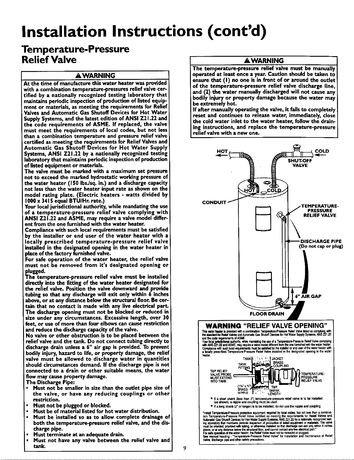
AWARNING
The temperature-pressure relief valve must be manually
operated at least once a year.Caution shouldbe taken to
ensurethat (I) no one isin front of or around the outlet
of the temperature-pressure relief valve discharge line,
and (2) the water manuallydischargedwill not causeany
bodily injury or property damage becausethe water may
be extremely hot.
If after manuallyoperating the valve,it failsto completely
reset and continuesto release water, immediately, close
the coldwater inlet to the water heater, followthe drain-
ing instructions, and replace the temperature-pressure
relief valvewith a newone.
H_OT I COLD
.<-.-
SHUT-OFF
VALVE
PRESSURE
RELIEF VALVE
(Do not cap or plug)
6" AIR GAP
FLOOR DRAIN
WARNING "RELIEF VALVE OPENING"
tt_m_,_d _ _l_f v_ andAutor_cGasS_tollD_¢_ _ HOfwar_ _ _°°q_l_
_ _ME. •
Y0_k_ " _',orify,*Hiemanm_ngh_ meofaTerrC_ramre_°res,_reI_e_fValve¢mP,Y,ng
TANK :_' '\_, !' JACKET
TANK * '1, _ BRASS
FITT G COUPLING
T&P RELIEF _
VALVE PROBE TEMPERATURE-
MUST E<TEND PRESSURE
INTO TANK , RELIEF VALVE
1/." x /,'
• Ifa sho_ shank(less than 2') temperature-pressuren_liefvalve is Io be installed
(asshown),a n_pp_eand ccuplingn_Jstbe ueed.
• Ifa Io_gshank(2" orIo_er) Isto beinstalled,donot use6_eofpple andcoupifng
•lr_aif Tempe_urePressurepro_Az_eequipmentrequire_bylocalo0Oes,bulnotlessthana ¢etina-
bonTemperatu_Pressure Relief VaNe certifiedas ri_e_n the {equirementsfor ReliefVah/esaf_l
Aut0n-a_GasShu_ D_CeS kx Hot-WaterSupplySystems,_'_S Z2122_ a r,atior_'=yreco_zz_ _ -
mustb_ermnted,p_ovi_KIv_htub_, _ o_e_i_ inmlledso_at disease _n ex_0r_y_n B_
_ove, _ atm_ydimn_ belo_them_uraJ fl0¢{,and¢ann_ 0or_a_anyI_ ek_n_l _.
F0_safe_ of_hewate¢he_t_,_e I_i_ Val_ mustr_ be lemoved_ if_
See mlnual heading- "Tempererure-Pressu!eRet_efValve"for installaEona_ mainte_nce of Relief
Vofve,_lscha,gepipeandog',ersafetyprer.,au',w)ns.
Installation Instructions (cont'd)
Filling the Water Heater
To fill the water heater with water:
• Close the water heater drain valve by turning the handle to
the right (clockwise). The drain valve is on the lower front of
the water heater.
• Open the cold water supply valve to the water heater.
NOTE: The cold water supply valve must be left open
when the water heater is in use.
• To insure complete filling of the tank, allow air to exit by
opening the nearest hot water faucet. Allow water to run
until a constant flow is obtained. This will let air out of the
water heater and the piping.
A CAUTION I
Never usethis water heater unlessit is completely full of I
water. To prevent damage to the tank and heating ele-
ment, the tank must be filled with water. Water must I
flow from the hot water faucet before turning "ON"
power,
• Check all new water piping for leaks. Repair as needed.
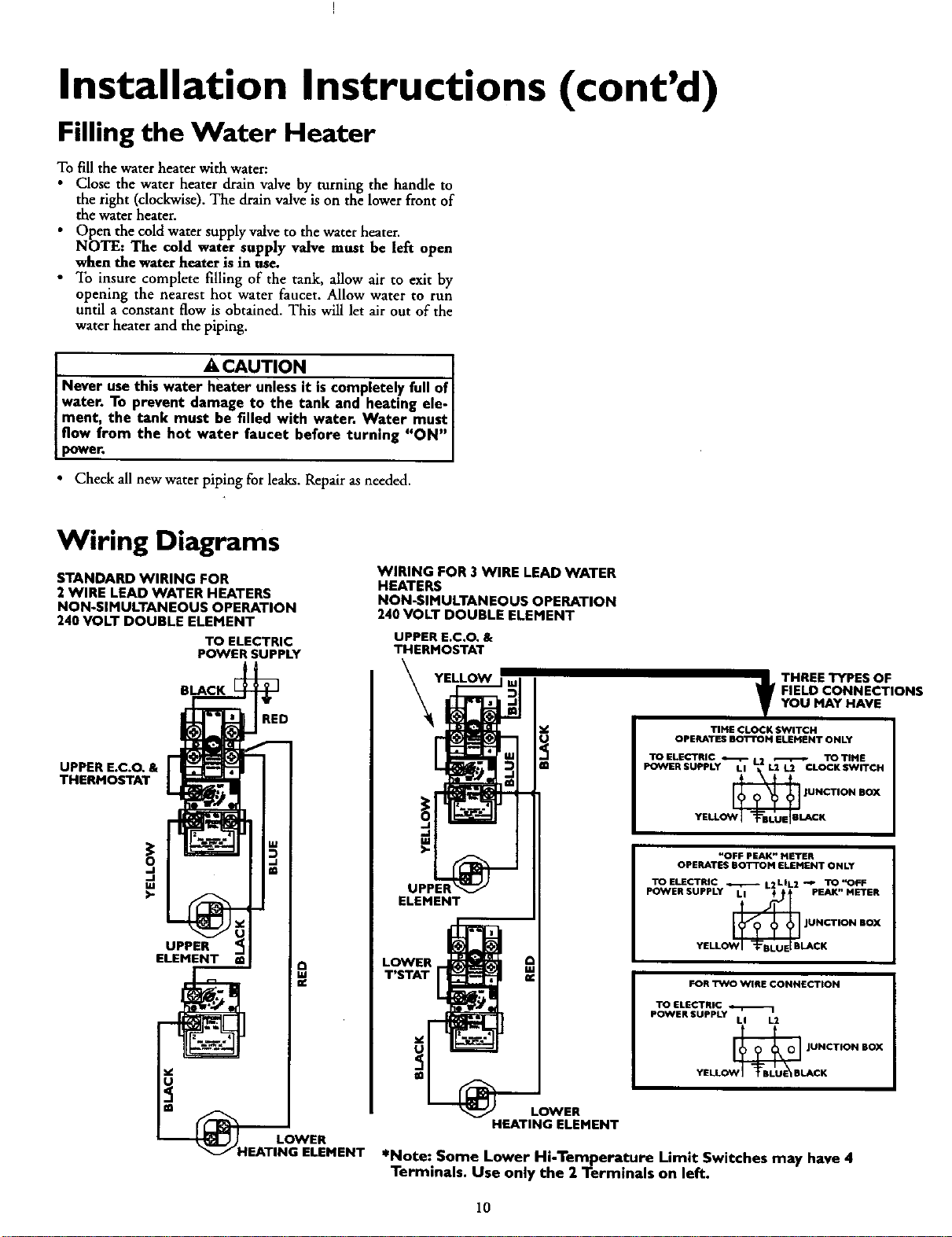
Wiring Diagrams
STANDARD WIRING FOR
2 WIRE LEAD WATER HEATERS
NON-SIMULTANEOUS OPERATION
240 VOLT DOUBLE ELEMENT
TO ELECTRIC
POWER SUPPLY
BLACK
RED
UPPER E.C.O. &
THERMOSTAT
UPPER
ELEMENT
@
LOWER
"IEATING ELEMENT
WIRING FOR 3 WIRE LEAD WATER
HEATERS
NON-SIMULTANEOUS OPERATION
240 VOLT DOUBLE ELEMENT
UPPER E.C.O, &
THERMOSTAT
YELLOW
u!_
ELEMENT
@
t HREE TYPES OF
FIELD CONNECTIONS
YOU MAY HAVE
TIME CLOCK SWITCH
OPERATES BOTTOM ELEMENT ONLY
TOELECTRIC _ L2 _ TOTIME
POWERSUPPLY LI L2 U CLOCK SWITCH
JUNCTION BOX
"OFF PEAK" METER
OPERATES BOTTOM ELEHENT ONLY
TOELECTRIC _ L2LIL2 -_ TO'_FF
POWER SUPPLY LI + PEAK" METER
_ JUN_--tlON BOX
YELL LACK
FOR TWO WIRE CONNECTION
TO ELECTRIC
POWER SUPPLY
LI L2
O_N_B JUNCTION BOX
YELL LACK
LOWER
HEATING ELEMENT
*Note: Some Lower Hi-Temperature Limit Switches may have 4
Terminals. Use only the 2 Terminals on left.
10
Installation Instructions (cont'd)
Wiring
A CAUTION .
Never usethis water heater unlessit is completely full ofI
water. To prevent damage to the tank and heating ele-
ment. the tank must be filled w_th water. Water must
flow from the hot water faucet beforeturning on power.
You must provide all wiring of the proper size outside of the
water heater.You must obey local codes and electric company
requirements when you install this wiring.
If you are not familiar with electric codes and practices, or if you
have any doubt, even the slightest doubt, in your ability to con-
nect the wiring to this water heater, obtain the service of a com-
petent electrician. Contact your Sears salesperson to arrangefor
a professional electrician.
C. Flexible metal conduit or flexible metallic tubing shall be
permitted for grounding if all the following conditions are
met:
1. The length in any ground return path does not exceed
6 feet.
2. The circuit conductors contained therein are _rotected
by overcurrent devices rated at 20 amperes or Jess.
3. The conduit or tubing is terminated in fittings
approved for grounding.
For complete grounding details and all allowable exceptions,
refer to the latest edition of the National Electrical Code.
4. A standard ½"conduit opening has been made in the water
heater junction box for the conduit connection.
AWARNING
WATER HEATERS EQUIPPED FOR ONE VOLTAGE
ONLY: Thiswater heater isequippedfor one type voltage
only.Check the rating plate near the bottom accesspanel
for the correct voltage. DO NOT use this water heater
with any voltage other than the one shownon the model
rating plate. Failure to usethe correct voltage can cause
problems whichcan result in DEATH. SERIOUS BODILY
INJURY,OR PROPERTY DAMAGE. If you haveany ques-
tionsor doubtsconsultyour electric company.
ACAUTION
If wiring from your fuse box or circuit breaker box was
aluminum for your old water heater, replace it with cop-
per wire. Ifyou wish to reuse the existingaluminum wire,
havethe connection at the water heater made bya com-
petent electrician. Contact your Sears salesperson to
arrangefor a professionalelectrician.
,
Wiring Diagrams (See Wiring Diagrams Section) have been
supplied showing the two most common types of connec-
tions between the water heater and the power supply. You can
easily see which type connection you have by removing the
junction box cover on top of the water heater.
A. Two Ware Connection Diagrams: is the most common
requiring you to simply connect red to red, black to black,
and the ground wire to the green ground screw in the junc-
tion box of the water heater.
B. Three Wire Connection Diagram: is used when you are
connecting the water heater to power a supply that has a
"Time Clock" or "Off Peak" Meter. To make these connec-
tions refer to block 1or 2 in this wiring diagram for the type
of system you have.
NOTE: If you have purchased a three wire connection
water heater but you are not on a "Time Clock" or "Off
Peak" meter and have a standard two wire connection
lower supply, simply follow the connection diagram in
lock 3. of the Three Wire Connection Diagram.
1. Provide away to easily shut off the electric power when work-
ing on the water heater. This could be with a circuit breaker
or fuse block in the entrance box or a separate disconnect
switch.
2. Install and connect a circuit directly from the main fuse or
circuit breaker box. This circuit must be the right size and
have irs own fuse or circuit breaker. Refer to the chart in the
_Product Specifications" section for the correct size wire and
fuse or circuit breaker.
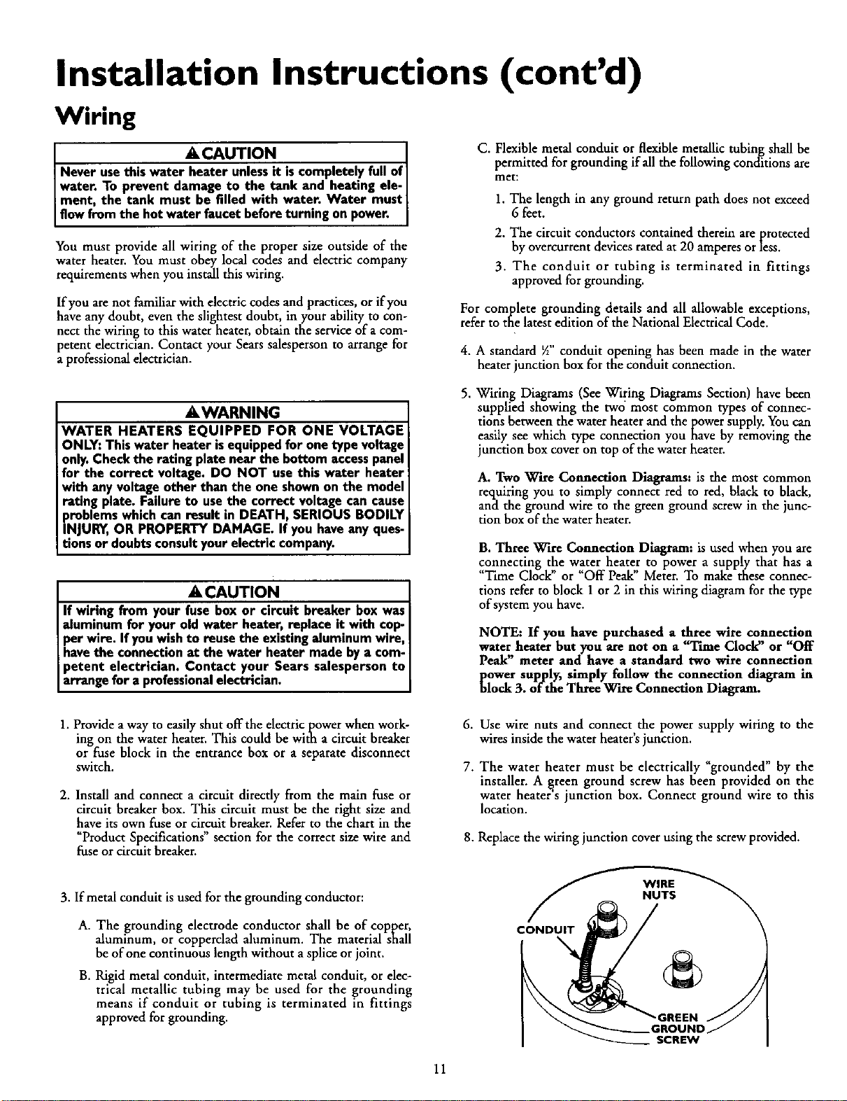
6.
7.
Use wire nuts and connect the power supply wiring to the
wires inside the water heater's junction.
The water heater must be electrically "grounded" by the
installer. A _reen ground screw has been provided on the
water heater s junction box. Connect ground wire to this
location.
8. Replace the wiring junction cover using the screw provided.
3. If metal conduit is used for the grounding conductor:
A. The grounding electrode conductor shall be of copper,
aluminum, or copperclad aluminum. The material shall
be of one continuous length without a splice or joint.
B. Rigid metal conduit, intermediate metal conduit, or elec-
trical metallic tubing may be used for the grounding
means if conduit or tubing is terminated in fittings
approved for grounding.
CONDUIT
11
Installation Instructions (cont'd)
Installation Checklist
• Is the fuse or circuit breaker size correct as shown in the chart
in the "Product Specifications" section?
• Are the wires from the circuit breaker or fuse service to the
water heater's junction box on the correct wire size (gauge) as
shown in the chart in the _Product Specifications" section?
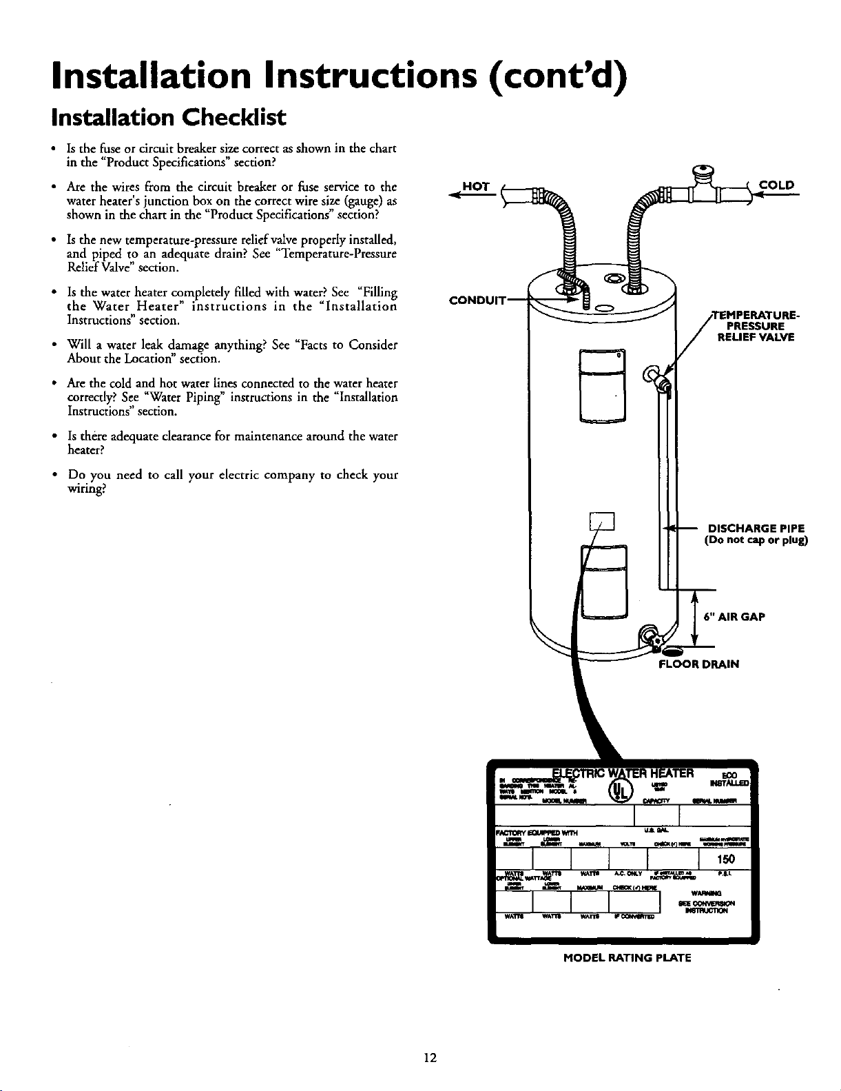
• Is the new temperature-pressure relief valve properly installed,
and piped to an adequate drain? See "Temperature-Pressure
Relief Valve" section.
• Is the water heater completely filled with water. See Fllhng
the Water Heater" instructions in the "Installation
Instructions" section.
• Will a water leak damage anything? See _Facts to Consider
About the Location" section.
• Are the cold and hot water lines connected to the water heater
correcdy? See "Water Piping" instructions in the _Installation
Instructions" section.
• Is there adequate clearance for maintenance around the water
heater?
• Do you need to call your electric company to check your
wiring?
COLD
PRESSURE
RELIEF VALVE
DISCHARGE PIPE
(Do not cap or plug)
6" AIR GAP
FLOOR DRAIN
MODEL RATING pLATE
12
Service and Adjustment
Temperature Regulation
_WARNING
HOTTER WATER CAN SCALD: Water heaters are
intended to produce hot water. Water heated to a tem-
perature whichwill satisfyspaceheating,clotheswashing,
dish washing, and other sanitizing needs can scald and
permanently injure you upon contact. Some people are
more likelyto be permanently injured by hot water than
others. These include the elderly,children, the infirm, or
physically/mentally handicapped. If anyone using hot
water in your home fits into one of these groups or if
there is a localcode or state law requiring a certain tem-
mrature water at the hot water tap, then you must take
specialprecautions.In addition to usingthe lowest possi-
ble temperature setting that satisfies your hot water
needs, a means such as a mixing valve, shall be used at
the hot water taps used by these people or at the water
heater. Mixing valvesare available at plumbing supplyor
hardware stores. Follow manufacturers instructions for
installation ofthe valves.Before changingthe factory set-
ting on the thermostat, read the "Temperature
Regulation"sectionin this manual.
The lower thermostat is factory set at a position which approxi-
mates 120°F (Hot) and is adjustable ifa different water tempera-
ture is desired. Read all warnings in this manual and on the
water heater before proceeding.
Nmll 4
AWARNING
Never allow small children to use a hot water tap, or to
draw their own bath water, Never leave a child or handi-
cappedpersonunattended na bathtub or shower.
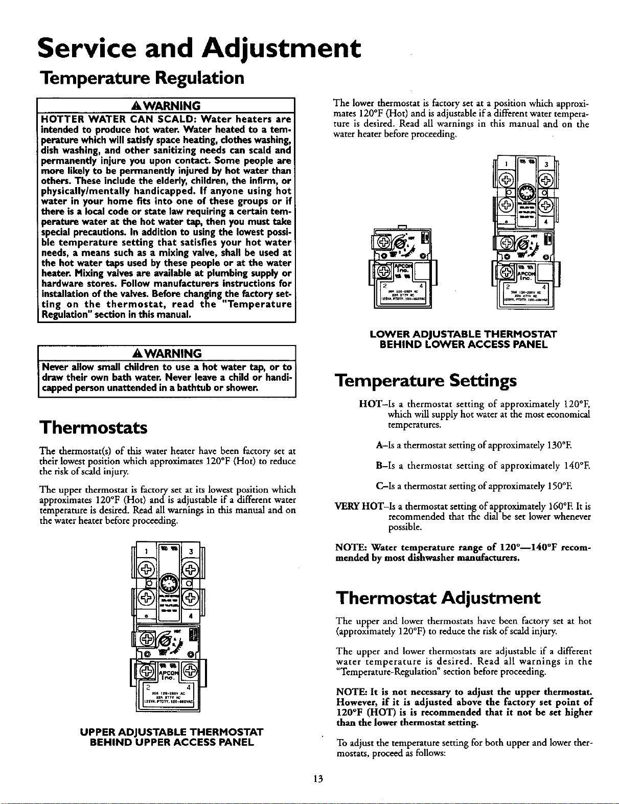
Thermostats
The thermostat(s) of this water heater have been factory set at
their lowest position which approximates 120°F (Hot) to reduce
the risk of scald injury.
The upper thermostat is factory set at its lowest position which
approximates 120°F (Hot) and is adjustable if a different water
temperature is desired. Read allwarnings in this manual and on
the water heater before proceeding.
LOWER ADJUSTABLE THERMOSTAT
BEHIND LOWER ACCESS PANEL
Temperature Settings
HOT-Is a thermostat setting of approximately 120°F,
which will supply hot water at the most economical
temperatures.
A-Is athermostat setting of approximately 130°E
B-Is a thermostat setting of approximately 140°E
C-Is athermostat setting of approximately 150°E
VERY HOT-Is a thermostat setting of approximately 160°E It is
recommended that the dial be set lower whenever
possible.
f =u
UPPER ADJUSTABLE THERMOSTAT
BEHIND UPPER ACCESS PANEL
NOTE: Water temperature range of 120°--140°F recom-
mended by most dishwasher manufacturers.
Thermostat Adjustment
The upper and lower thermostats have been factory set at hot
(approximately 120°F) to reduce the risk of scald injury.
The upper and lower thermostats are adjustable if a different
water temperature is desired. Read all warnings in the
"Temperature-Regulation" section before proceeding.
NOTE: It is not necessary to adjust the upper thermostat.
However, if it is adjusted above the factory set point of
120°F (HOT) is is recommended that it not be set higher
than the lower thermostat setting.
To adjustthe temperature setting for both upper and lower ther-
mostats, proceed as follows:
13
Service and Adjustment (cont'd)
Thermostat Adjustment (cont'd)
• Turn _OFF" the electrical power to the water heater at the
junction box.
A WARNING
HAZARD OF ELECTRICAL SHOCK! Before removing
any accesspanels or servicing the water heater, make
sure the electrical suppl.yto the water.heater is turned
"OFF". Failure to do this could result m DEATH, SERI-
OUS BODILY NJURY,OR PROPERTY DAMAGE.
A WARNING
If the temperature-pressure relief valve on the appliance
weeps or dischargesperiodically,this may be due to ther-
mal expansion.Your water heater may havea checkvalve
installedin the water line or a water meter with a check
valve. Consultyour local SearsServiceCenter for further
information. Do not plug the temperature-pressure relief
valve.
• Takeoffthe (upper or lower) access panel
• The slotted adjustment (using a screwdriver) can be turned
clockwise (_L_ J) to increase the temperature setting or
counter clock_7-se (k.._...) t ) to decrease the temperature
settmg.
• Replacethe access panel.
• Turn _ON" the power supply.
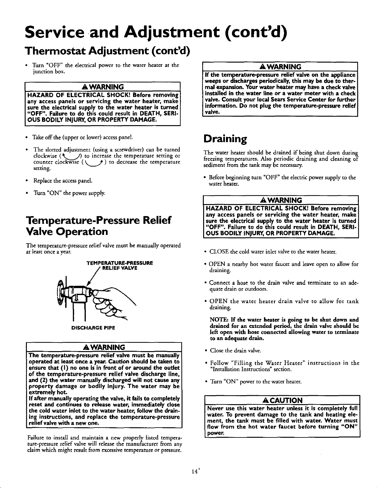
Temperature-Pressure Relief
Valve Operation
The temperature-pressure relief valve must be manually operated
at least once a year.
TEMPERATURE-PRESSURE
DISCHARGE PIPE
AWARNING be manually
The temperature-pressure relief valve must
Ioperated at least once a year:Caution shouldbetaken to
ensurethat (I) no one is in front of or around the outlet
of the temperature-pressure relief valve dischargeline,
and (2) the water manually dischargedwill not causeany
property damage or bodily injury. The water may be
extremely hot.
If after manuallyoperating the valve, it failsto completely
reset and continues to release water, immediately close
the coldwater inlet to the water heater,follow the drain-
ing instructions, and replace the temperature-pressure
relief valvewith a new one.
Failure to install and maintain a new properly listed tempera-
tore-pressure relief valve will release the manufacturer from any
dalm which might result from excessive temperature or pressure.
Draining
The water heater should be drained if being shut down during
freezing temperatures. Also periodic draining and cleaning of
sediment from the tank may be necessary.
• Before beginning turn "OFF" the electric power supply to the
water heater.
A WARNING ]
HAZARD OF ELEC_Kf Before removing_
any access panels or servicing the water heater, make_
sure the electrical supply to the water heater is turned |
"OFF". Failure to do this could result in DEATH, SERI-]
OUS BODILY INJURY,OR PROPERTY DAMAGE. ]
• CLOSE the cold water inlet valve to the water heater.
• OPEN a nearby hot water faucet and leave open to allow for
draining.
• Connect a hose to the drain valve and terminate to an ade-
quate drain or outdoors.
• OPEN the water heater drain valve to allow for tank
draining.
NOTE: If the water heater is going to be shut down and
drained for an extended period, the drain valve should be
left open with hose connected allowing water to terminate
to an adequate drain.
• Close the drain valve.
• Follow "Filling the Water Heater" instructions in the
"Installation Instructions" section.
• Turn "ON" power to the water heater.
A CAUTION
Never usethis water heater unlessit is completely full I
water. To prevent damage to the tank and heating ele- I
iment, the tank must be filled with water. Water must
flow from the hot water faucet before turning "ON"
power.
14'
Service and Adjustment (cont'd)
Element Cleaning/
Replacement
NOTE: These instructions are written for element cleaning
and element replacement for the lower dement. If it is neces-
sary to clean or replace the upper element, then repeat these
instructions.
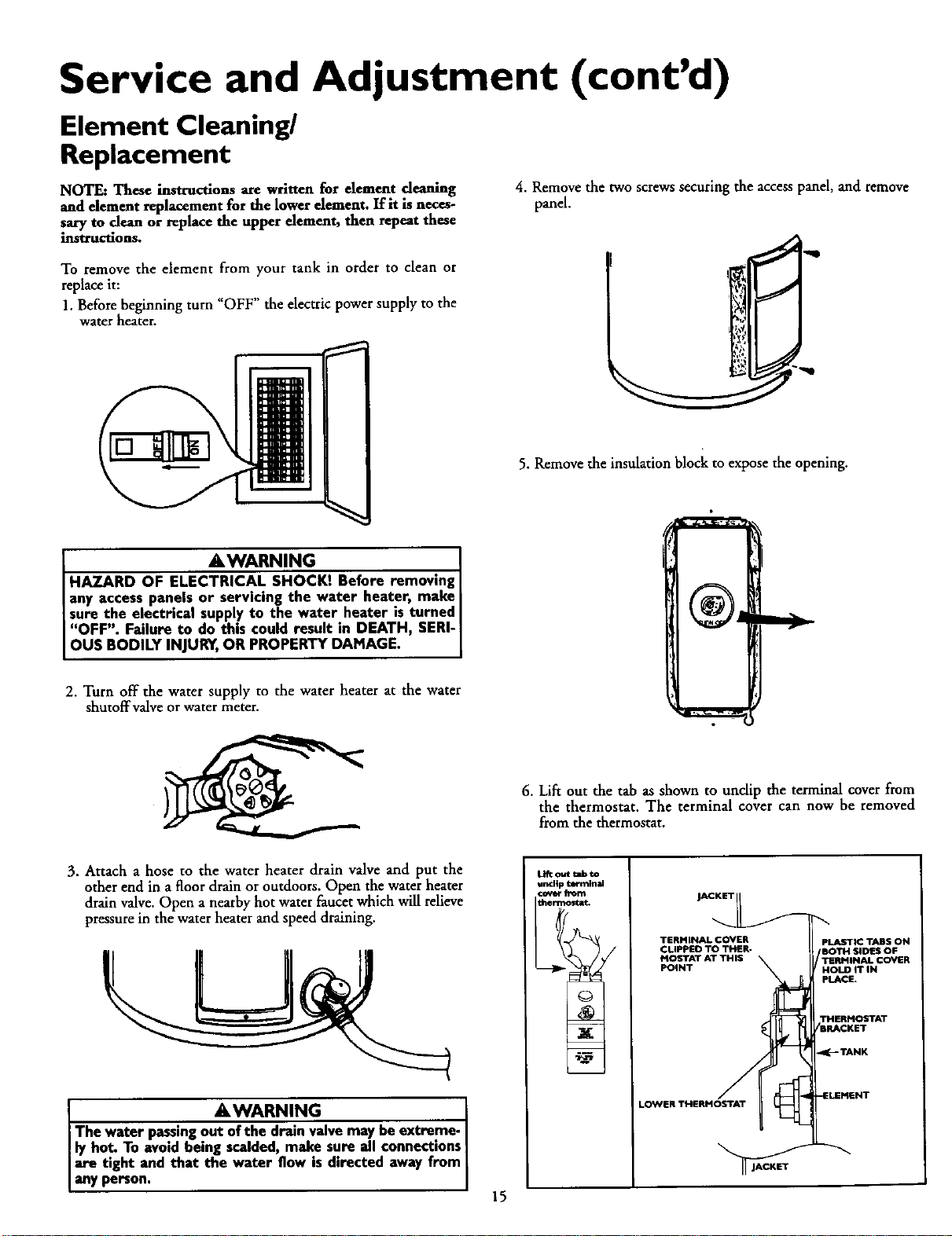
4. Remove the two screws securing the accesspanel, and remove
panel.
To remove the element from your tank in order to clean or
replace it:
1. Before beginning turn "OFF" the electric power supply to the
water heater.
5. Remove the insulation block to expose the opening.
&WARNING
HAZARD OF ELECTRICAL SHOCK! Before removing I
I any accesspanels or servicing the water heater, make
I sure the electrical supply to the water heater is turned I
I "OFF". Failure to do this could result in DEATH, SERI-I
OUS BODILY INJURY,OR PROPERTY DAMAGE. [
1
2. Turn off the water supply to the water heater at the water
shutoffvalve or water meter.
3. Attach a hose to the water heater drain valve and put the
other end in a floor drain or outdoors. Open the water heater
drain valve. Open a nearby hot water faucet which will relieve
pressure in the water heater and speed draining.
. AWARNING
The water pas.smgout of the drain valvemay be extreme- I
ly hot. To avoid being scalded,make sure all connections I
are tight and that the water flow is directed away from
anyperson.
15
6. Lift out the tab as shown to tmclip the terminal cover from
the thermostat. The terminal cover can now be removed
from the thermostat.
LI_ out lalb tal
uncllp tel'mlnal
JACKET
TERMINAL COVER PLASTIC TABS ON
CLIPPED TO THER- BOTH SIDES OFM OSTAT AT_TERMTHIS INAL COVER
POINT OLD IT IN
pLACE.
LO_NERTHERMOSTAT
Service and Adjustment (cont'd)
Element Cleaning/
Replacement (cont'd)
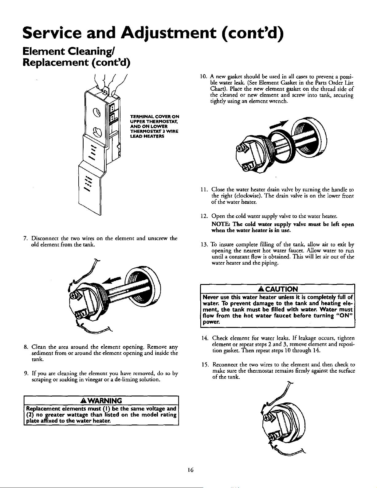
10. A new gasket should be used in all cases to prevent a possi-
ble water leak. (See Element Gasket in the Parts Order List
Chart). Place the new element gasket on the thread side of
the cleaned or new element and screw into tank, securing
tightly using an element wrench.
TERMINAL COVER ON
UPPER THERMOSTAT,
AND ON LOWER
THERMOSTAT 3 WIRE
LEAD HEATERS
7. Disconnect the two wires on the element and unscrew the
old element from the tank.
8. Clean the area around the element opening. Remove any
sediment from or around the element opening and inside the
tank.
9. If you are cleaning the element you have removed, do so by
scraping or soaking in vinegar or a de-liming solution.
AWARNING
Replacement elements must (I) be the same voltage and I
(2) no greater wattage than listed on the model rating
p ate affixedto the water heater.
11.
12.
13.
Close the water heater drain valve by turning the handle to
the right (clockwise). The drain valve is on the lower front
of the water heater.
Open the cold water supply valveto the water heater.
NOTE: The cold water supply valve must be left open
when the water heater is in use.
To insure complete filling of the tank, allow air to exit by
opening the nearest hot water faucet. Allow water to run
until a constant flow is obtained. This will let air out of the
water heater and the piping.
A CAUTION .
Never use this water heater unlessit Jscompletely full of J
water. To prevent damage to the tank and heating ele- ]
ment, the tank must be filled with water. Water must
flow from the hot water faucet before turning "ON" J
power. [
14. Check element for water leaks. If leakage occurs, tighten
element or repeat steps 2 and 3, remove element and reposi-
tion gasket. Then repeat steps 10 through 14.
15. Reconnect the two wires to the element and then check to
make sure the thermostat remains firmly against the surface
of the tank.
16
Service and Adjustment (cont'd)
Drain Valve Washer
Replacement
16. Replace terminal cover on thermostat making sure that the
locking tabs on the terminal cover are in place.
17. Replace the insulation block so that it completely covers the
thermostat and element.
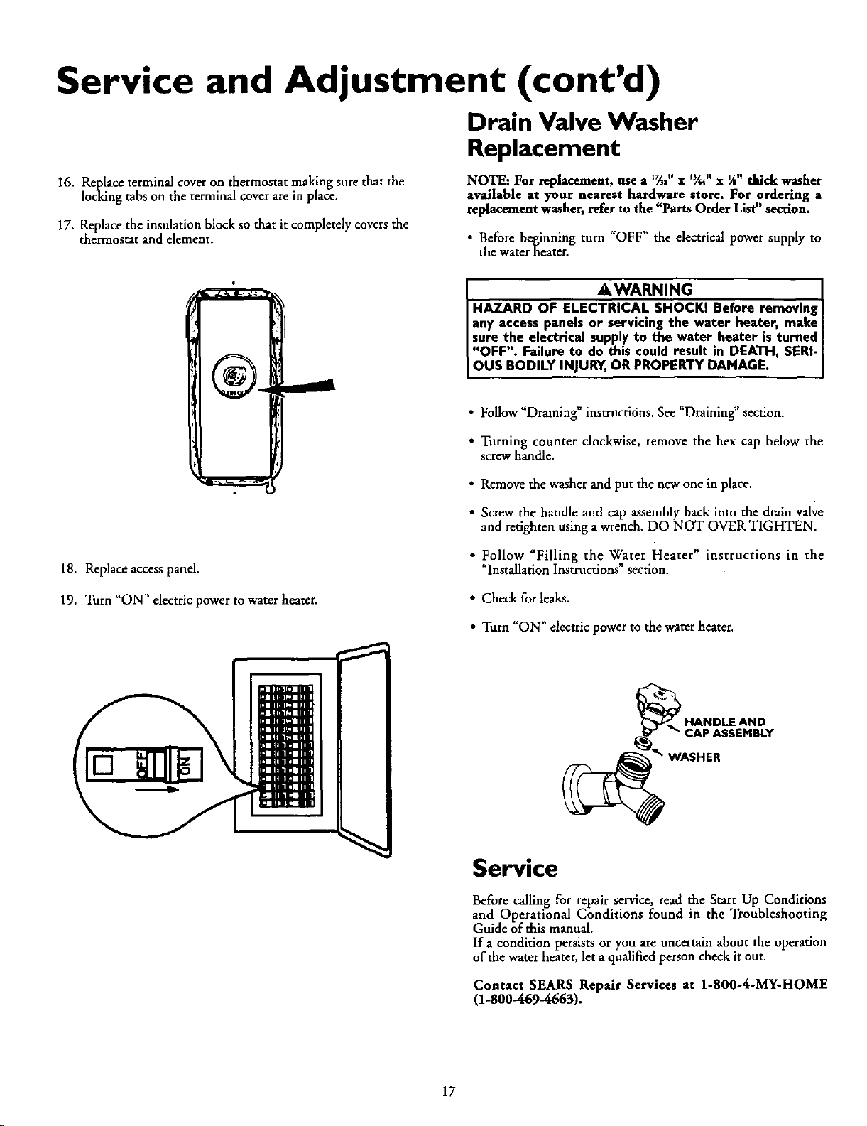
NOTE: For replacement, use a I%2" x 13/,, x IA"thick washer
available at your nearest hardware store. For ordering a
replacement washer, refer to the "Parts Order List" section.
• Before beginning turn "OFF" the electrical power supply to
the water heater.
18. Replace accesspanel.
19. Turn "ON" electric power to water heater.
_,WARNING
HAZARD OF ELECTRICAL SHOCKI Before removing
any access panels or servicing the water heater, make I
[ sure the electrical supplyto the water.heater is turned I
I "OFF". Failure to do this could result in DEATH, SERI-I
[ OUS BODILY INJURY,OR PROPERTY DAMAGE. ]
• Follow "Draining" instructions. See "Draining" section.
• Turning counter clockwise, remove the hex cap below the
screw handle.
• Remove the washer and put the new one in place.
• Screw the handle and cap assembly back into the drain valve
and retighten using a wrench. DO NOT OVER TIGHTEN.
• Follow "Filling the Water Heater" instructions in the
_Installation Instructions" section.
• Check for leaks.
• Turn "ON" electric power to the water heater.
CAP ASSEMBLY
rASHER
Service
Before calling for repair service, read the Start Up Conditions
and Operational Conditions found in the Troubleshooting
Guide of this manual.
If a condition persists or you are uncertain about the operation
of the water heater, let a qualified person check it out.
Contact SEARS Repair Services at 1-800-4-MY-HOME
(1-800-469-4663).
17
Troubleshooting Guide
Start Up Conditions
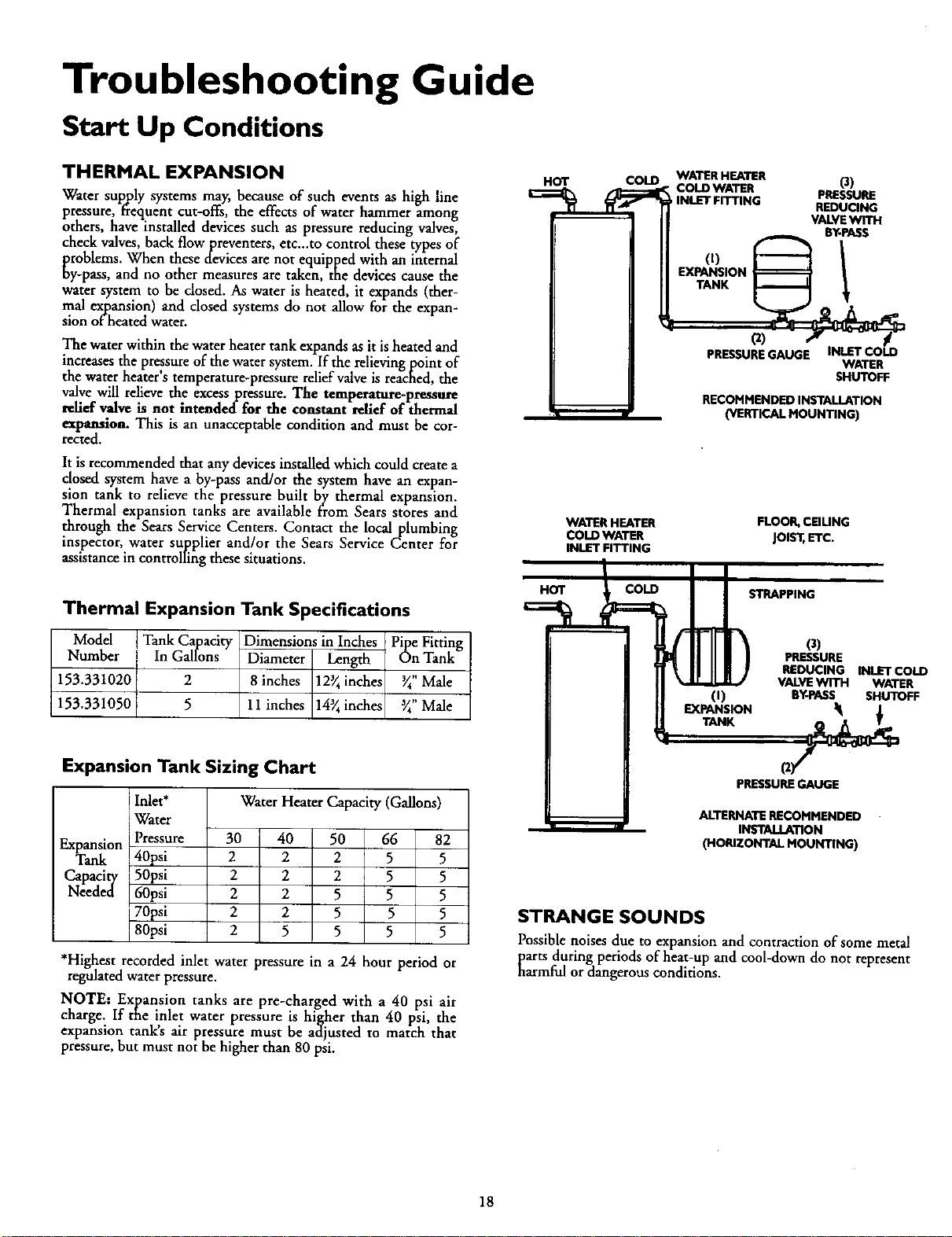
THERMAL EXPANSION
Water sup yysspJls tems may, because of such events as high line
pressure, frequent cut-offs, the effects of water hammer among
others, have installed devices such as pressure reducing valves,
check valves, back flowpreventers, etc...to control these types of
problems. When these devices are not equipped with an internal
oy-pass, and no other measures aretaken, the devices cause the
water system to be dosed. As water is heated, it expands (ther-
mal expansion) and closed systems do not allow for the expan-
sion of heated water.
The water within the water heater tank expands as it is heated and
increases the pressure of the water system. If the relieving point of
the water heater's temperature-pressure relief valve is reached, the
valve will relieve the excess pressure. The temperature-pressure
relief valve is not intended for the constant relief of thermal
expansion. This is an unacceptable condition and must be cor-
rected.
It is recommended that any devices installed which could create a
closed system have a by-pass and/or the system have an expan-
sion tank to relieve the pressure built by thermal expansion.
Thermal expansion tanks are available from Sears stores and
through the Sears Service Centers. Contact the local plumbing
inspector, water supplier and/or the Sears Service Center for
assistancein controlling these situations.
Thermal Expansion Tank Specifications
Model ITank Capacity Dimensions in Inches :Pipe Fitting
Number In Gallons Diameter Length On Tank
153.331020 2 8 inches 12_ inches _" Male
153.331050 5 11 inches 14_ inches _" Male
HOT
COlD
WATER HEATER
COlD WATER
INLET FITTING
WATER HEATER
colD WATER (3)
PRESSURE
, INLET FITTING REDUCING
VALVEWITH
BY-PASS
(t) 1
EXPANSION
TANK
PRESSUREGAUGE INLET COlD
WATER
SHUTOFF
RECOMMENDED INSTALLATION
(VERTICAL MOUNTING)
FLOOR, CEILING
JOIS'l_,ETC.
STRAPPING
O)
EXPANSION
0)
PRESSURE
REDUCING INLET COlD
VALVEWITH WATER
BY-PASS SHUTOFF
Expansion Tank Sizing Chart
Water Heater Capacity (Gallons)
Inlet*
Water
Pressure
40psi
50psi
60psi
70psi
80psi
Expansion 30 40 50 66 82
Tank 2 2 2 5 5
Capacity 2 2 2 5 5
Needed 2 2 5 5 5
2 2 5 5 5
2 5 5 5 5
*Highest recorded inlet water pressure in a 24 hour period or
regulated water pressure.
NOTE: Expansion tanks are pre-charged with a 40 psi air
charge. If the inlet water pressure is higher than 40 psi, the
expansion tanks air pressure must be adjusted to match that
pressure, but must not be higher than 80 psi.
PRESSUREGAUGE
ALTERNATE RECOMMENDED
INSTALLATION
(HORIZONTAL MOUNTING)
STRANGE SOUNDS
Possible noises due to expansion and contraction of some metal
parts during periods of heat-up and cool-down do not represent
harmful or dangerous conditions.
18
Troubleshooting Guide (cont'd)
Operational Conditions
SMELLY WATER HIGH TEMPERATURE SHUT OFF SYSTEM
In each water heater there is installed at least one anode rod (see
parts section) for corrosion protection of the tank. Certain water
conditions will cause a reaction between this rod and the water.
The most common com_0,l,aint associated with the anode rod is
one of a rotten egg smell'. This odor is derived from hydrogen
sulfide gas dissolved in the water. The smell is the result of four
factors which must all be present for the odor to develop:
a. a concentration of sulfate in the supply water.
b. little or no dissolved oxygen in the water.
c. a sulfate reducing bacteria within the water heater. (This
harmless bacteria is non-toxic to humans.)
d. an excess of active hydrogen in the tank. This is caused by
the corrosion protective action of the anode.
Smelly water may be eliminated or reduced in some water heater
models by replacing the anode(s) with one of less active material,
and then chlorinating the water heater tank and all hot water
lines. Contact the local Sears Service Center for further informa-
tion concerning an Anode Replacement Kit #9001453 and this
Chlorination Treatment.
If the smelly water persists after the anode replacement and chlo-
rination treatment, we can only suggest that continuous chlori-
nation and filtering conditioning equipment be considered to
eliminate the water problem.
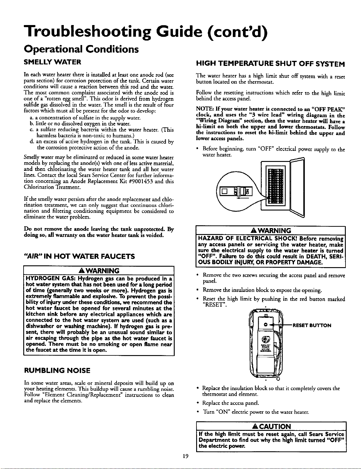
The water heater has a high limit shut off system with a reset
button located on the thermostat.
Follow the resetting instructions which refer to the high limit
behind the access panel.
NOTE: If your water heater is connected to an "OFF PEAK"
clock, and uses the "3 wire lead" wiring diagram in the
"Wh-ing Diagram" section, then the waterheater will have a
hi-limit on both the upper and lower thermostats. Follow
the instructions to reset the hi-limlt behind the upper and
lower access panels.
• Before beginning, turn "OFF" electrical power supply to the
water heater.
1
Do not remove the anode leaving the tank unprotected. By
doing so, all warranty on the water heater tank is voided.
"AIR" IN HOT WATER FAUCETS
akWARNING
HYDROGEN GAS: Hydrogen gas can be produced in a
hot water systemthat hasnot been usedfor a long period
of time (generally two weeks or more). Hydrogen gas is
extremely flammable and explosive.To prevent the possi-
bility of injury under these conditions,we recommend the
hot water faucet be opened for several minutes at the
kitchen sink before any electrical appliances which are
connected to the hot water system are used (such as a
dishwasheror washing machine). If hydrogengas is pre-
sent, there will probably be an unusualsound similar to
air escapingthrough the pipe as the hot water faucet is
opened. There must be no smoking or open flame near
the faucet at the time it isopen.
RUMBLING NOISE
In some water areas, scale or mineral deposits will build up on
your heating elements. This buildup will cause a rumbling noise.
Follow _Element Cleaning/Replacement" instructions to clean
and replace the elements.
AWARNING ]
HAZARD OF ELECTRICAL SHOCKI Before removing[
any access panels or servicing the water heater, make I
sure the electrical supplyto the water.heater is turned I
"OFF". Failure to do this could result m DEATH, SERI-
OUS BODILY INJURY,OR PROPERTY DAMAGE.
• Remove the two screws securing the access panel and remove
panel.
• Remove the insulation block to expose the opening.
• Reset the high limit by pushing in the red button marked
"RESET".
O _ 1RESET BUTTON
runner
• Replace the insulation block so that it completely covers the
thermostat and element.
• Replacethe accesspanel.
• Turn "ON" electric power to the water heater.
A CAUTION . ]
If the high limit mu_n,.call Sears Service I
Department to find out why the high hmit turned "OFF" ]
the electric power. ]
19
Troubleshooting Guide (cont'd)
NOT ENOUGH OR NO HOT WATER
In a new installation, the water heater may not be properly
connected. Make sure the cold water supply valve is open.
Review and check piping installation. Make sure that the
cold water line is connected to the cold water inlet to the
water heater and the hot water line to the hot water outlet
on the water heater.
Make sure the electrical supply to your water hearer is
_ONL
Check for loose or blown fuses in your water heater circuit.
Circuit breakers weaken with age and may not handle their
rated load and should be replaced.
Make certain the disconnect switch, if used, is in the "ON"
position.
Check to see the electric service to your house has not been
interrupted. If this is the case, contact the electric company.
Are the thermostats set to the desired temperature? See
"Temperature Regulation" section.
If you had experienced very hot water and now no hot
water, the problem may be due to the high temperature
shut off system. See High Temperature Shut Off System
in the "Toubleshooting" section.
During very cold weather, the incoming water will also be
colder and it will require a longer time to become heated.
The hot water usage may exceed the capacity of the water
heater. If so, wait for water heater to recover after abnormal
demand. Also examine pipes and faucets for possible water
leaks.
• If you can not determine the problem, then call the Sears
Service Department.
WATER IS TOO HOT
Adjust the thermostat to a lower setting. See the "Temperature
Regulation" section.
2O
Troubleshooting Guide (cont'd)
Leakage Checkpoints
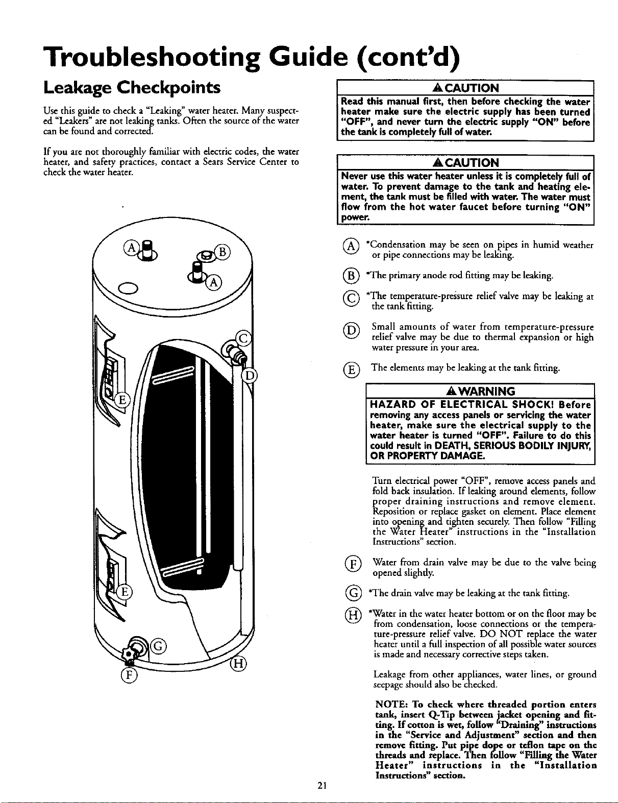
Use this guide to check a "Leaking" water heater. Many suspect-
ed _Leakers" are not leaking tanks. Often the source of the water
can be found and corrected.
If you are not thoroughly familiar with electric codes, the water
heater, and safety practices, contact a Sears Service Center to
check the water heater.
_,CAUTION . J
Read this manual first, then before checking the water I
,,beatermake sure the electrtc' supply has been turned I
OFF", and never turn the electric supply"ON" before
the tank scomp ete y fu of water.
• A, CAUTION J
Never usethis water heater unlessit iscomplete_ fullof
water. To prevent damage to the tank and heating ele- I
ment, the tank must be filled with water. The water mustJ
flow from the but water faucet before turning "ON"
power.
(_) *Condensation may be seen on pipes in humid weather
or pipe connections may be leaking.
*The primary anode rod fitting may be leaking.
Q'The temperature-pressure relief valve may be leaking at
the tank fitting.
(_) Small amounts of water from temperature-pressure
relief valve may be due to thermal expansion or high
water pressure In your area.
®
The elements may be leaking at the tank fitting.
_,WARNING
HAZARD OF ELECTRICAL SHOCKI Before
removing any accesspanelsor servicingthe water
beater, make sure the electrical supply to the
water beater is turned "OFF". Failure to do this
could result in DEATH, SERIOUS BODILY INJURY,
OR PROPERTY DAMAGE.
21
®
©
®
Turn electrical power "OFF", remove access panels and
fold back insulation. If leaking around elements, follow
proper draining instructions and remove element.
Reposition or replace gasket on element. Place e!ement
into opening and tighten securely. Then follow Filling
the Water Heater" instructions in the "Installation
Instructions" section.
Water from drain valve may be due to the valve being
opened slightly.
*The drain valve may be leaking at the tank fitting.
*Water in the water heater bottom or on the floor may be
from condensation, loose connections or the tempera-
ture-pressure relief valve. DO NOT replace the water
heater until a full inspection of all possible water sources
is made and necessary corrective steps taken.
Leakage from other appliances, water lines, or ground
seepage should also be checked.
NOTE: To check where threaded portion enters
tank, insert Q-Tip between jacket opening and fit-
ring. If cotton iswet, follow "Draining" instructions
in the "Service and Adjustment" section and then
remove fitting. Put pipe dope or teflon tape on the
threads and replace. Then follow "F'dling the Water
Heater" instructions in the "Installation
Instructions" section.
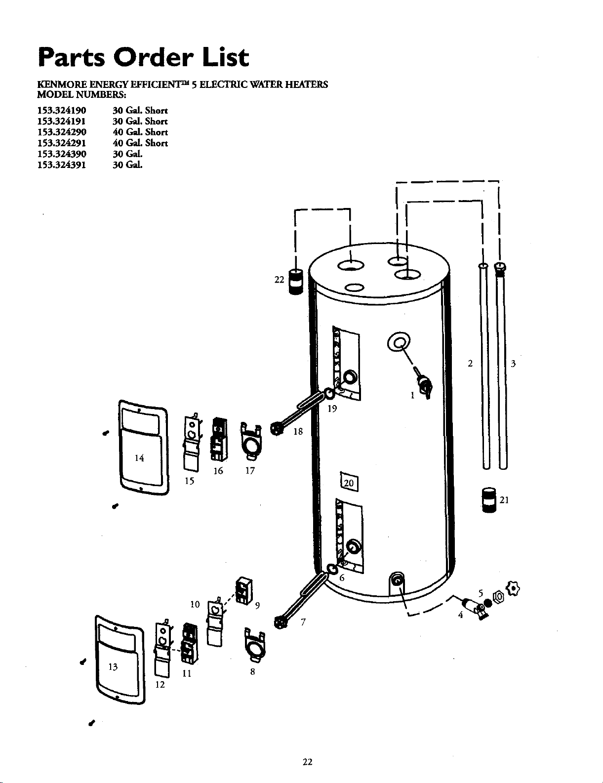
Parts Order List
KENMORE ENERGY EFFICIENT m 5 ELECTRIC WATER HEATERS
MODEL NUMBERS:
153.324190 30 Gal. Short
153.324191 30 Gal. Short
153.324290 40 Gal. Short
153.324291 40 Gal. Short
153.324390 30 Gal.
153.324391 30 Gal.
19
7
22
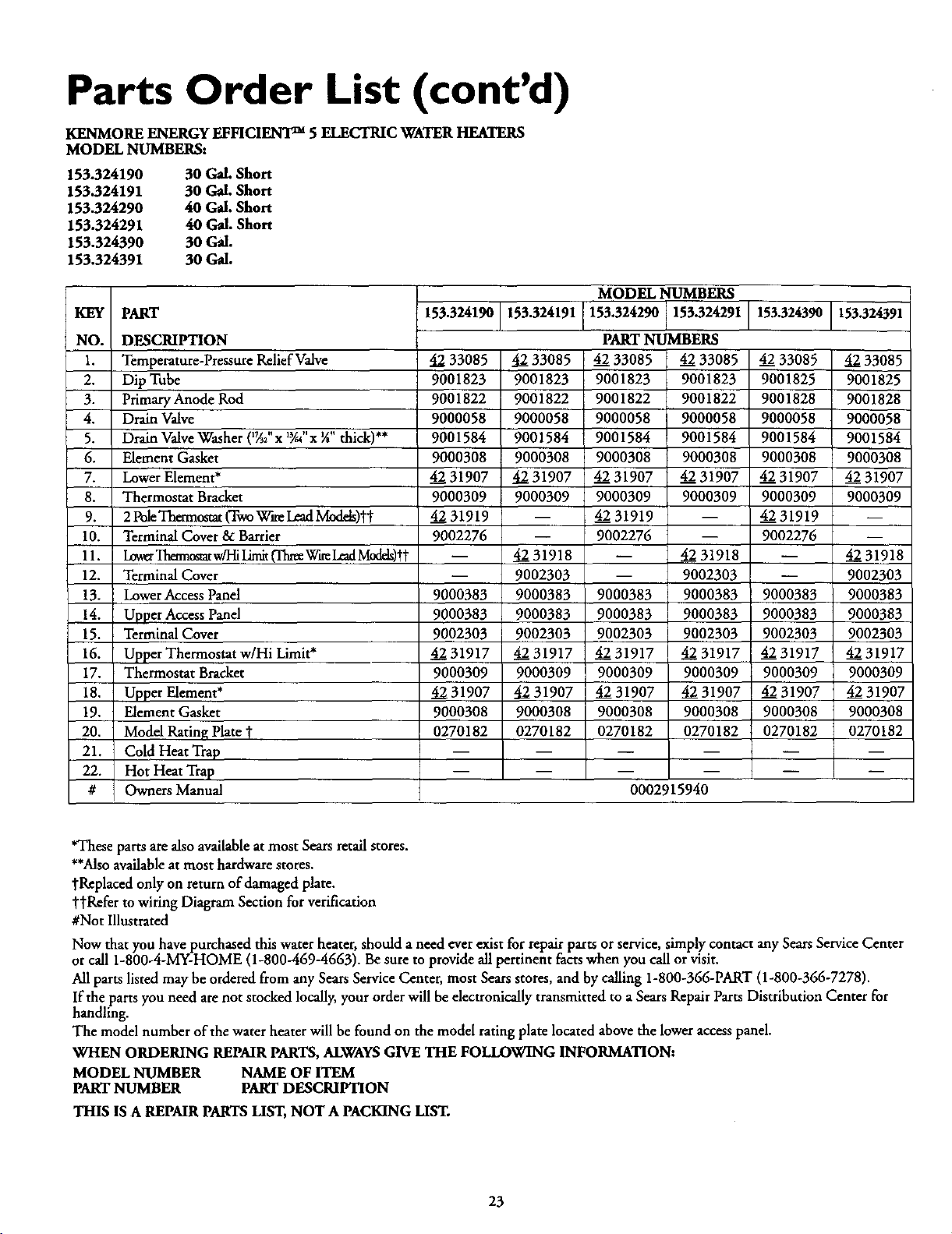
Parts Order List (cont'd)
KENMORE ENERGY EFFICIENT TM 5 ELECTRIC WATER HEATERS
MODEL NUMBERS:
153.324190 30 Gal. Short
153.324191 30 Gal. Short
153.324290 40 Gal. Short
153.324291 40 Gal. Short
153.324390 30 Gal.
153.324391 30 Gal.
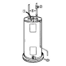
KEY PART
NO. DESCRIPTION
1. Temperature-PressureRelief Valve
2. Dip Tube
3. Primary Anode Rod
4. Drain Valve
5. Drain ValveWasher ('TA;'x *Y-"x ¼"thick) **
6. Element Gasket
7. Lower Element*
8. Thermostat Bracket
0. 2PoleThermostat (TwoWareLeadMod&)l"t"
Terminal Cover & Barrier
11. LowerTheanostatw/HiLimit0hree W_ LeadModds)tt
12. Terminal Cover
13. Lower Access Panel
14. Upper AccessPanel
15. Terminal Cover
16. Upper Thermostat w/Hi Limit*
17. Thermostat Bracket
18. Upper Element*
19. Element Gasket
20. Model Rating Plate
21. Cold Heat Trap
22. Hot Heat Trap
# Owners Manual
153,324190 153.324191 153.324390 153.324391
4233085
9001823
9001822
9000058
90O1584
9000308
4231907
9000309
4231919
9002276
4233085
9001823
9001822
9000058
9001584
9000308
4231907
9000309
4233O85
9O01825
9001828
9000058
9001584
9000308
4231907
9000309
4231919
9002276n
42_31918
9002303
9000383
9000383
9002303
4231917
9000309
4231907
9000308
0270182
MODEL NUMBERS
153.324290 153.324291
PART NUMBERS
4233085 4233085
9001823 9001823
9001822 9001822
9000058 9000058
9001584 9001584
9000308 9000308
4231907 4231907
9000309 9000309
4231919 --
9002276 --
-- 4231918
-- 9002303
9000383 9000383
9000383 9000383
9002303 9002303
4231917 4231917
9000309 9000309
4231907 4231907
9000308 9000308
0270182 0270182
0002915940
4233085
9001825
9001828
9000058
9001584
9000308
4231907
9000309
m
9000383 9000383
9000383 9000383
9002303 9002303
4231917 4231917
9000309 9000309
4231907 4231907
9000308 9000308
0270182 0270182
m
4231918
9002303
90O0383
9000383
9002303
4231917
9000309
4231907
9000308
0270182
*These parts are also available at most Sears retail stores.
**Alsoavailable atmost hardware stores.
"j'Replacedonly on return of damaged plate.
"['j'Raferto wiring Diagram Section for verification
#Not Illustrated
Now that you have purchased this water heater, should a need ever exist for repairparts or service, simply contact any SearsService Center
orcall 1-800-4-MY-HOME (1-800-469-4663). Be sure to provide all pertinent facts when you call or visit.
All parts listed may be ordered from any Sears Service Center, most Sears stores, and by calling 1-800-366-PART (1-800-366-7278).
If the parts you need are not stocked locally, your order will be electronically transmitted to a Sears RepairParts Distribution Center for
handling.
The model number of the water beater will be found on the model rating plate located above the lower access panel.
WHEN ORDERING REPAIR PARTS, ALWAYSGIVE THE FOLLOWING INFORMATION:
MODEL NUMBER NAME OF ITEM
PART NUMBER PART DESCRIPTION
THIS ISA REPAIR PARTS LIST, NOT A PACKING LIST.
23

Parts Order List
KENMORE ENERGY EFFICIENT _ 5 ELECTRIC WATER HEATERS
MODEL NUMBERS:
153.324490 40 Gal.
153.324491 40 Gal.
153.324690HT 40 Gal. Medium
153.324691HT 40 Gal. Medium
153.324792 50 Gal.
153.324793 50 Gal.
14
16 17
_ 15
22
19
7
24
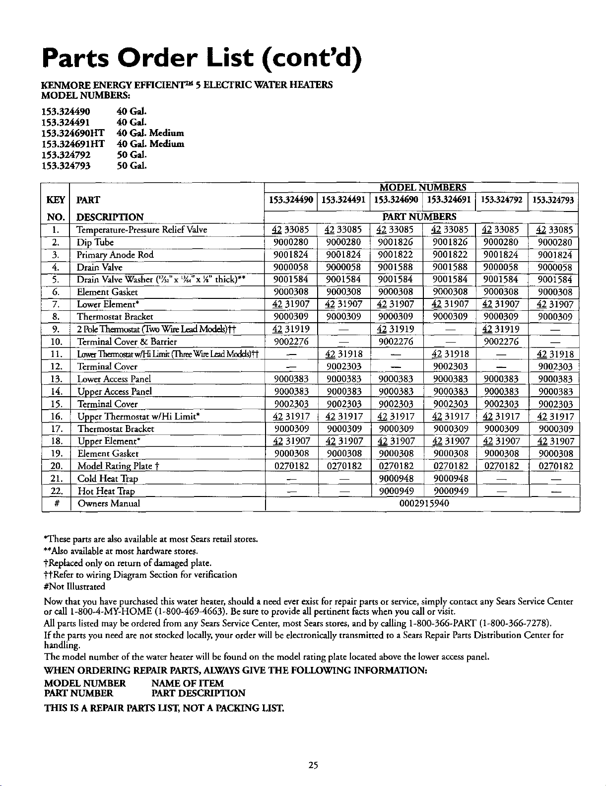
Parts Order List (cont'd)
KENMORE ENERGY EFFICIENT TM 5 ELECTRIC WATER HEATERS
MODEL NUMBERS:
153.324490 40 Gal.
153.324491 40 Gal.
153.324690HT 40 Gal. Medium
153.324691HT 40 Gal. Medium
153.324792 50 Gal.
153.324793 50 Gal.
KEY PART
NO. DESCRIPTION
1. Temperature-Pressure Relief Valve
2. Dip Tube
3. Primary Anode Rod
4. Drain Valve
5. Drain ValveWasher (_;' x %" x X" thick)**
6. Element Gasket
7. Lower Element*
8. Thermostat Bracket
9. 2 PoleThermostat(TwoWineLeadModds)'H"
10. Terminal Cover 8,:Barrier
11. LowerThmncstatw/HiLimit(ThreeWireLeadModds)'_"
12. Terminal Cover
13. Lower Access Panel
14. Upper Access Panel
15. Terminal Cover
16. Upper Thermostat w/Hi Limit*
17. Thermostat Bracket
18. Upper Element*
19. Element Gasket
20. Model Rating Plate *
21. Cold Heat Trap
22. Hot Heat Trap
# Owners Manual
MODEL NUMBERS
153.324490 153.324491 153.324690 153.324691 153.324792 153.324793
4233085
9000280
9001824
9000058
9001584
9000308
4231907
9000309
4231919
9002276
9000383
9000383
9002303
4231917
9000309
4231907
9000308
0270182
4233085
9000280
9001824
9000058
9001584
9000308
4231907
9000309
m
4231918
9002303
9000383
9000383
9002303
4231917
9000309
4231907
9000308
0270182
PART NUMBERS
.42_33085 _J_33085
9001826 9001826
9001822 9001822
9001588 9001588
9001584 9001584
9000308 9000308
4_31907 4_2231907
9000309 9000309
4_31919 --
9002276 --
-- 4231918
-- 9002303
9000383 9000383
9000383 9000383
9002303 9002303
4231917 42231917
9000309 9000309
4231907 _;231907
9000308 9000308
0270182 0270182
9000948 9000948
9000949 9000949
0002915940
4233085
9000280
9001824
9000058
9001584
9000308
4231907
9000309
4231919
9002276
9000383
9000383
9002303
4231917
9000309
4231907
9000308
0270182
4_2233085
9000280
9001824
9000058
9001584
9000308
4231907
9000309
m
4231918
9002303
900O383
9000383
9002303
4231917
9000309
4231907
9000308
0270182
*These parts are also available at most Sears retail stores.
**Also available at most hardware stores.
tReplaced only on return of damaged plate.
yJ'Refer to wiring Diagram Section for verification
#Not Illustrated
Now that you have purchased this water heater, should a need ever exist for repairparts or service, simply contact any Sears Service Center
orcall 1-800-4-MY-HOME (1-800-469-4663). Be sure to provide all pertinent facts when you call orvisit.
All parts listed may be orderedfrom any Sears Service Center, most Sears stores, and by calling 1-800-366-PART (1-800-366-7278).
If the parts you need are not stocked locally,your orderwill be electronically transmitted to a Sears Repair Parts Distribution Center for
handling.
The model number of the water heater will be found on the model rating plate located above the lower accesspanel.
WHEN ORDERING REPMR PARTS,ALWAYS GIVE THE FOLLOWING INFORMATION:
MODEL NUMBER NAME OF ITEM
PARTNUMBER PARTDESCRIPTION
THIS IS A REPAIR PARTS LIST, NOT A PACKING LIST.
25

Notes
26

Notes
27
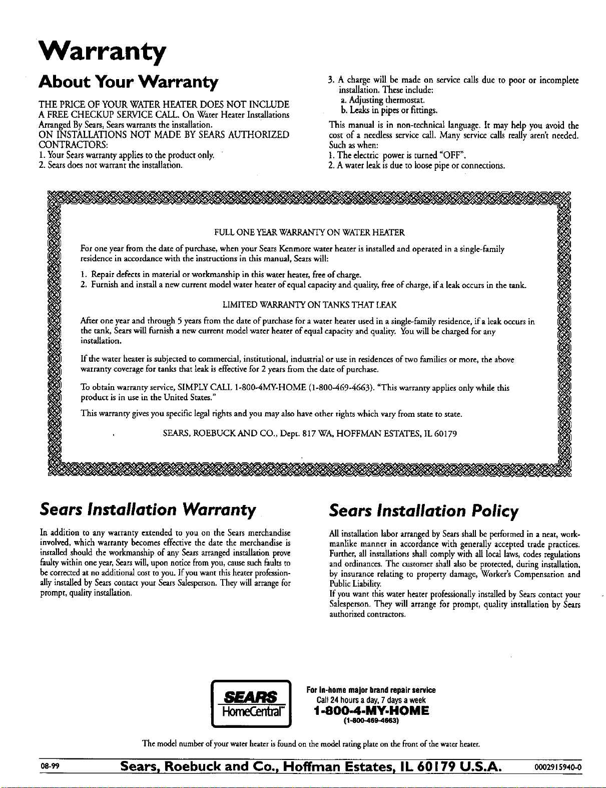
Warranty
About Your Warranty
THE PRICE OF YOUR WATERHEATERDOES NOT INCLUDE
A FREECHECKUP SERVICECALL.On Water Heater Installations
ArrangedBySears,Searswarrantsthe installation.
ON INSTALLATIONS NOT MADE BYSEARSAUTHORIZED
CONTRACTORS:
1.YourSearswarrantyapplies to the product only.
2. Searsdoesnot warrant the installation.
3. A charge will be made on service calls due to poor or incomplete
installation.These include:
a. Adjustingthermostat.
b. Leaksin pipesor fittings.
This manual is in non-technical language.It may help you avoid the
cost of a needlessservicecall. Many servicecalls really arent needed.
Such aswhen:
1.The electric poweristurned =OFF".
2. Awaterleakis due to loosepipe or connections.
FULLONE YEARWARRANTY ON WATER HEATER
For one year from the date of purchase, when your Sears Kenmore water heater is installed and operated in a single-family
residence in accordance with the instructions in this manual, Sears will:
1. Repair defects in material or workmanship in this water heater, free of charge.
2. Furnish and install a new current model water heater of equal capacity and quality, free of charge, ifa leak occurs in the rank.
LIMITED WARRANTY ON TANKSTHAT LEAK
After one year and through 5 years from the date of purchase for a water heater used in a single-family residence, ifa leak occurs in
the tank, Sears will furnish a new current model water heater of equal capacity and quality. You will be charged for any
installation.
If the water heater is subjected to commercial, institutional, industrial or use in residences of two families or more, the above
warranty coverage for tanks that leak is effective for 2 years from the date of purchase.
To obtain warranty service, SIMPLY CALL 1-800-4MY-HOME (1-800-469-4663). =This warranty applies only while this
product is in use in the United States."
This warranty gives you specific legal rights and you may also have other rights which vary from state to state.
SEARS, ROEBUCK AND CO., Dept. 817 WA, HOFFMAN ESTATES, IL 60179
Sears Installation Warranty
In addition to any warranty extended to you on the Sears merchandise
involved, which warranty becomes effective the date the merchandise is
installed should the workmanship of any Sears arranged installation prove
faultywithin one year,Sears will,upon notice from you, causesuch faults to
be corrected at no additionalcost to you. If you want this heater profession-
ally installed by Sears contact your Sears Salesperson. They will arrangefor
prompt, quality installation.
Sears Installation Policy
Allinstallationlaborarrangedby Searsshallbeperformedina neat,work-
manlike manner in accordance withgenerallyaccepted trade practices.
Further,all inst_ations shallcomplywithall locallaws,codesregulations
and ordinances.The customershallalsobe protected,duringinstallation,
by insurancerelating to propertydamage,Worker'sCompensation and
PublicLiability.
Ifyou wantthiswaterheaterprofessionallyinstalledby Searscontactyour
Salesperson.They will arrange for prompt, quality installationbySears
authorizedcontractors.
ForIn-homemajorbrandrepairservice
Call24hoursaday,7daysaweek
1-800-4-MY.HOME
(1-800-469-4663)
The model number ofyourwater heateris foundon the model ratingplate on the front of thewater heater.
o8-. Sears, Roebuck and Co., Hoffman Estates, IL 60179 U.S.A. 0zsls94 0