
Loading ...
Loading ...
Loading ...
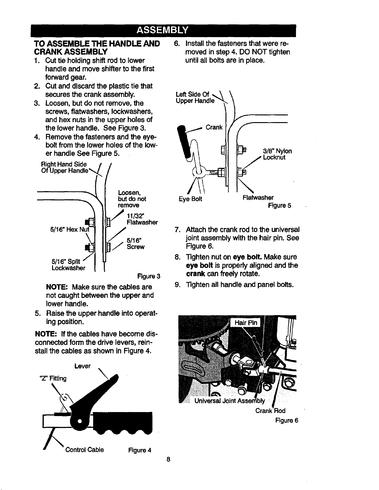
TO ASSEMBLE THE HANDLE AND
CRANK ASSEMBLY
1. Cut tie holding shift rod to lower
handle and move shifter to the first
forward gear.
2. Cut and discard the plastic tie that
secures the crank assembly.
3. Loosen, but do not remove, the
screws, flatwashers, Iockwashers,
and hex nuts in the upper holes of
the lower handle. See Figure 3.
4. Remove the fasteners and the eye-
bolt from the lower holes of the low-
er handle See Figure 5,
htHand Side
5/16" Hex
Loosen,
but do not
remove
11/32"
Fiatwasher
5/16"
Screw
.
5/1_' _
Lockwasher
Figure 3
NOTE: Make sure the cables are
not caught between the upper and
lower handle.
Raise the upper handle intooperat-
ing position.
NOTE: If the cables have become dis-
connectedform the drive levers, rein-
stallthe cables as shown in Figure 4.
Lever
"Z" Fitting _,
6. Install the fasteners that were re-
moved in step 4. DO NOT tighten
until all bolts are in place.
Left Side Of
3/8" Nylon
Eye Bolt Flatwasher
Figure 5
7. Attach the crank rod to the universal
joint assembly with the hair pin. See
Figure 6.
8. Tighten nut on eye bolt. Make sure
eye bolt is properlyaligned and the
crank can freely rotate.
9. "13ghtenall handle and panel bolts.
Universal
Crank ::led
Figure 6
Control Cable Figure 4
8
Loading ...
Loading ...
Loading ...