Loading ...
Loading ...
continued from page 3
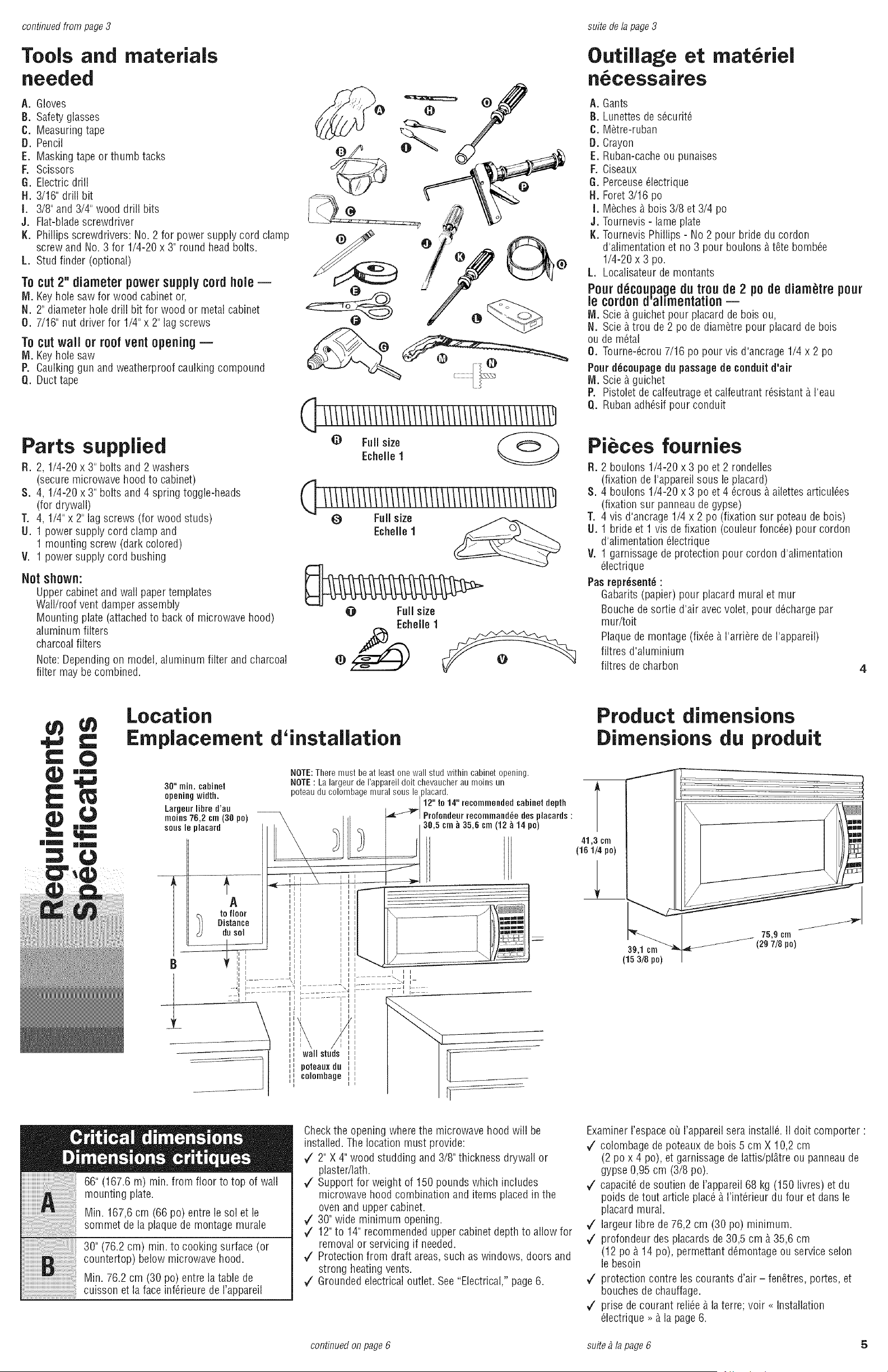
Tools and materials
needed
A. Gloves
B. Safetyglasses
C. Measuringtape
D. Pencil
E. Maskingtape or thumb tacks
F. Scissors
G. Electricdrill
H. 3/16" drill bit
I. 3/8" and3/4" wood drill bits
J. Flat-bladescrewdriver
K. Phillips screwdrivers: No. 2 for powersupply cord clamp
screw and No. 3 for 1/4-20 x 3" round headbolts.
L. Stud finder (optional)
Tocut 2" diameter power supply cordhole=
NI. Keyhole saw for wood cabinet or,
N. 2" diameter hole drill bit for wood or metal cabinet
O. 7/16" nut driver for 1/4" x 2" lag screws
Tocut wall or roof ventopening --
Nl. Keyhole saw
P. Caulking gun and weatherproof caulking compound
Q. Ducttape
suite de lapage 3
Outillage et mat6riel
n6cessaires
A. Gants
B. Lunettesde s6curit6
C. M6tre-ruban
D. Crayon
E. Ruban-cacheou punaises
F. Ciseaux
6. Perceuse61ectrique
H. Foret3/16 pc
I. M6ches_ bois 3/8 et 3/4 pc
J. Tournevis- lame plate
I(. TournevisPhillips - No 2 pour bridedu cordon
d'alimentation et no 3 pour boulonsb t6te bomb6e
1/4-20 x 3 pc.
L. Localisateurde montants
Pour d_coupage du trou de 2 po de diam_tre pour
le cordond'ahmentation =
IVl.Scie_ guichet pour placardde bois ou,
N. Scieb trou de2 pc de diam6tre pour placardde bois
ou de m6tal
O. Tourne-6crou 7/16 pc pour vis d'ancrage 1/4x 2 pc
Pour d_¢eupage du passagede conduit d'air
Nl. Scie_ guichet
P. Pistoletde calfeutrageetcalfeutrant r6sistant _ I'eau
Q. Rubanadh6sif pour conduit
Parts supplied
R. 2, 1/4-20 x 3" bolts and 2 washers
(secure microwave hood to cabinet)
8. 4, 1/4-20 x 3" bolts and 4 spring toggle-heads
(for drywall)
T. 4, 1/4"x 2"lag screws (for wood studs)
U. 1 power supply cord clamp and
1 mounting screw (dark colored)
V. 1 power supply cord bushing
Not shown:
Uppercabinet and wall paper templates
Wall/roof vent damper assembly
Mounting plate (attachedto backof microwave hood)
aluminum filters
charcoal filters
Note:Dependingon model, aluminum filter andcharcoal
filter may be combined.
0 Full size
Echelle 1
0 Full size
Echelle 1
@ Full size
_ Echelle 1
Pi ces fournies
R. 2 boulons 1/4-20 x 3 pc et 2 rondelles
(fixation de I'appareil sous le placard)
S. 4 boulons 1/4-20 x 3 pc et4 6crous & ailettesarticul6es
(fixation sur panneaude gypse)
T. 4 vis d'ancrage 1/4 x 2 pc (fixation sur poteaude bois)
U. 1 bride et 1 vis de fixation (couleur fonc6e) pour cordon
d'alimentation 61ectrique
V. 1 gamissagede protection pour cordon d'alimentation
_lectrique
Pas represent6:
Gabarits (papier) pour placard mural et mur
Bouchede sortie d'air avec volet, pour d6chargepar
mur/toit
Plaquede montage (fix6e &I'arri@rede I'appareil)
filtres d'aluminium
filtres de charbon
4
Location
Emplacement d'installation
30" min. ¢ahinet
opening width.
Largeurlihre d'au
moths 76,2 ¢m (3g po)
sous le placard
A
to floor
Distance
dusol
B
--71 '
NOTE:There must be at least one wall stud within cabinet opening.
NOTE: Lalargeur de I'appareil dolt chevaucher au moins un
poteau du colombage mural sous leplacard.
112"to14"resommended¢ahieetdepth
.. Ill - _i 30,5 cm _ 35,6 cm (12 _ 14 pc)
atmlmm
i...... I I
' ...... I:......
.......... \ I I.... .]
I I I
wall studs
poteaox du
colombage
Product dimensions
Dimensions du produit
T
41,3 cm
(161/4pc)
39,1 sm
(153/8po)
75,9 cm
(2_ 7/8 pc)
66" (167.6 m) min. from floor to top of wall
mounting plate.
Min. 167,6cm (66 pc) entre le sol et le
sommet de la plaquede montage murale
30" (76.2 cm) min. to cooking surface (or
countertop) below microwave hood.
Min. 76.2 cm (30pc) entre la table de
cuisson et la face inf_rieure de I'appareil
Checkthe opening wherethe microwave hood will be
installed. Thelocation must provide:
7 2" X 4" wood studding and 3/8"thickness drywall or
plaster/lath.
7 Support for weight of 150 pounds which includes
microwave hood combination and items placedin the
ovenand upper cabinet.
7 30"wide minimum opening.
7 12"to 14"recommendedupper cabinet depth to allow for
removal or servicing if needed.
7 Protectionfrom draft areas,such as windows, doors and
strong heating vents.
7 Grounded electrical outlet. See "Electrical," page6.
Examiner I'espaceoQI'appareil serainstallS.II dolt comporter :
7 colombage de poteaux de bois 5 cm X 10,2 cm
(2 pc x 4 pc), et garnissage de lattis/pl_tre ou panneaude
gypse 0,95 cm (3/8 pc).
7 capacit_de soutien de I'appareil68 kg (150 livres) et du
poids detout article plac__ I'int_rieur du four et dansle
placard mural.
7 largeur libre de 76,2 cm (30 pc) minimum.
7 profondeur desplacards de 30,5 cm _ 35,6 cm
(12 pc _ 14 pc), permettant d_montage ou service selon
le besoin
7 protection centre lescourants d'air - fen6tres, portes, et
bouches de chauffage.
7 prise de courant reli_e _ la terre; voir _ Installation
_lectrique >>_ la page 6.
continuedon page6 suite _la page 6 5
Loading ...
Loading ...
Loading ...