30"
GAS
SLIDE-IN
RANGE
INSTALLATION
INSTRUCTIONS
(Models
with
Sealed
Top
Burners)
INSTALLATION
AND
SERVICE
MUST
BE
PERFORMED
BY
A
QUALIFIED
INSTALLER.
IMPORTANT:
SAVE
FOR
LOCAL
ELECTRICAL
INSPECTOR'S
USE.
READ
AND
SAVE
THESE
INSTRUCTIONS
FOR
FUTURE
REFERENCE.
If
the
information
in
this
manual
is
not
followed
exactly,
a
fire
or
explosion
may
result
causing
property
damage,
personal
injury
or
death.
FOR
YOUR
SAFETY:
—
Do
not store
or
use
gasoline
or
other
flammable
vapors
and
Appliances
Installed
in
the
state
of
liquids
in
the
vicinity
of
this
or
any
other
appliance.
Massachusetts:
—
WHAT
TO
DO
IF
YOU
SMELL
GAS:
This
Appliance
can
only
be
installed
in
the
¢
Do
not
try
to
light
any
appliance.
state
of
Massachusetts
by
a
Massachusetts
¢
Do
not
touch
any
electrical
switch;
do
not
use
any
phone
in
licensed
plumber
or
gasfitter.
your
building.
This
appliance
must
be
installed
with
a
¢
Immediately
call
your
gas
supplier
from
a
neighbor's
phone.
three
(3)
foot
/
36
in.
long
flexible
gas
Follow
the
gas
supplier's
instructions.
connector.
e
if
you
cannot
reach
your
gas
supplier,
call
the
fire
department.
A"T"
handle
type
manual
gas
valve
must
—
Installation
and
service
must
be
performed
by
a
qualified
be
installed
in
the
gas
supply
line
to
this
installer,
service
agency
or
the
gas
supplier.
appliance.
30"
Min.
WALL
|
(76.2
cm
Min.)
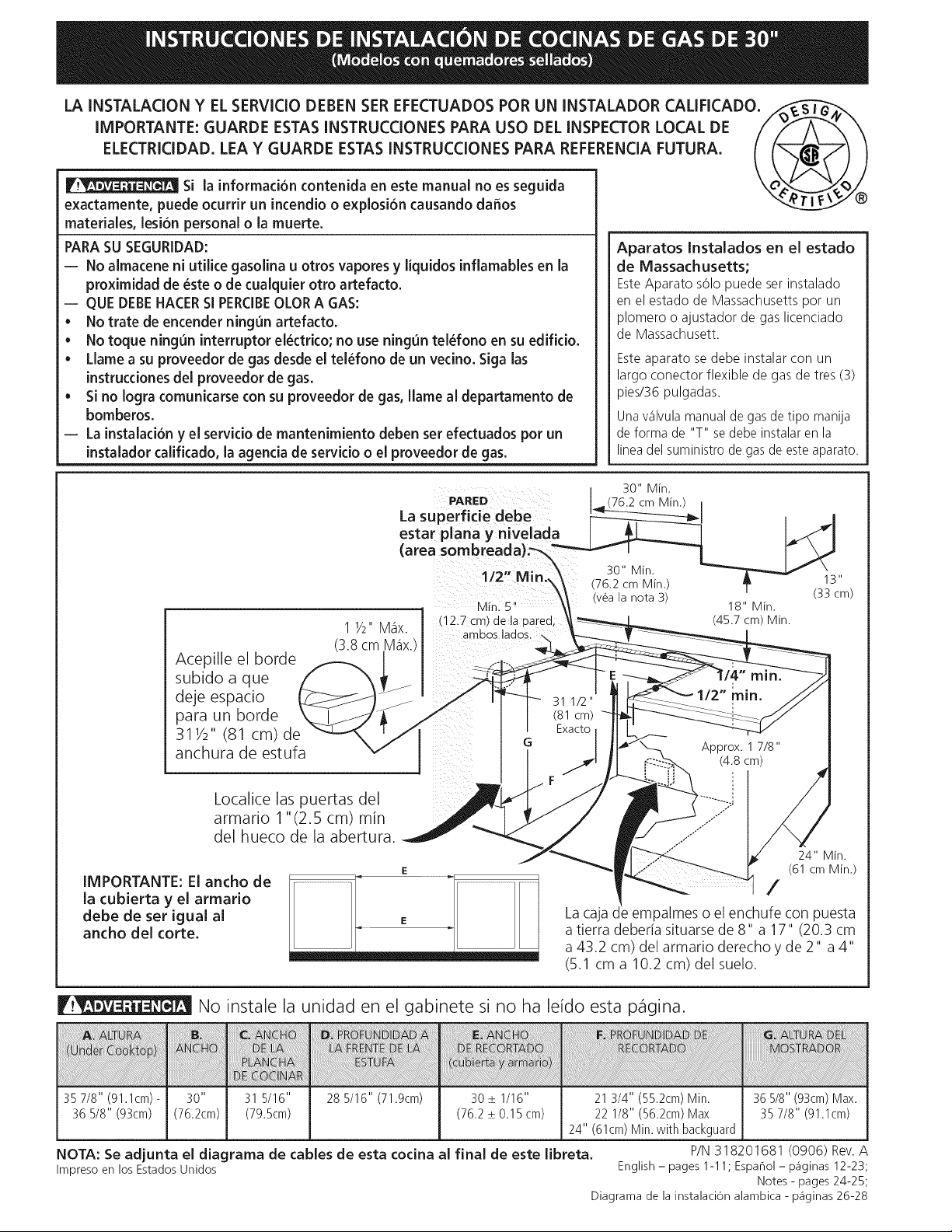
These
surfaces
should
—_,|
be
flat
&
leveled
(hatched
area).
30”
Min.
1/2”
Min.
(76.2
cm)
Min.
13°
5"
Min.
(see
Note
3)
12"
Min
(33
cm)
(12.7-cm:
Min.)
1
Vo"
Max.
From
Wall
Both
Sides.
“"""==
L
(45.7
cm)
Min.
Shave
Raised
B.8cm
Max.)
|
oo
Soe
Sy)
pee
OO
Edge
to
Clear
~~
‘
:
Space
for
a
315/16"
min
(81
cm)
Wide
(81
cm)
Cooktop.
See
Exact
Dimension
C
in
Approx.
1
7/8"
table.
ety
(4.8
cm)
Locate
Cabinet
Doors
1°
(2.5
cm)
-
Min.
from
Cutout
Spening
a
IMPORTANT:
Cabinet
and
countertop
width
|
|
should
match
the
/
|
Grounded
Junction
Box
or
Wall
Outlet
Should
Be
cutout
width.
E
|
Located
8"
to
17"
(20.3
cm
to
43.2
cm)
From
Right
Cabinet
and
2"
to
4"
(5.1
cm
to
10.2
cm)
From
Floor.
24"
Min.
(61
cm
Min.)
J
Do
not
install
the
unit
in
the
cabinet
before
reading
next
page.
A
HEGH]
CCOOKIOP|
DIO
AL
DePI
a
IO
BE.
CUIOUL
WIDIH
BE
CUIOU)
DEPTH
GHEGH)
(Under
—
wae
WIDTH
FRONT
OF
RANGE
—
and
cabinet)
OF
COUNTERTOP
1.9cm)
35
7/8"
28
5/16
'
(76.2+0.15cm)
1
3/4"
(55.2cm)
Min.
|
36
5/8"
(93cm)
Max.
36
5
Tose
6
Oem
tio,
oe
2
1/8"
eg
oem
Max
35
7/8"
(91.
ie
34°
(61cm)
Min.
with
backguard
NOTE:
Wiring
diagram
for
these
appliances
are
enclosed
in
this
booklet.
P/N
318201692
(1007)
Rev.
A
Printed
in
United
States
English
—
pages
1-11;
Espanol
-
paginas
12-23;
Notes
-
pages
24-25;
Wiring
Diagram
-
page
26-28
30"
GAS
SLIDE-IN
RANGE
INSTALLATION
INSTRUCTIONS
(Models
with
Sealed
Top
Burners)
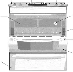
NOTES:
&
Do
not
pinch
the
power
supply
cord
between
the
range
and
the
wall.
@)
Do
not
seal
the
range
to
the
side
cabinets.
24"
(61
cm)
minimum
clearance
between
the
cooktop
and
the
bottom
of
the
cabinet
when
the
bottom
of
wood
or
metal
cabinet
is
protected
by
not
less
than
1/4"
(0.64
cm)
flame
&)
retardant
millboard
covered
with
not
less
than
No.
28
MSG
sheet
metal,
0.015"
(0.4
mm)
Stainless
steel,
0.024"
(0.6
mm)
aluminum,
or
0.020"
(0.5
mm)
copper.
30"
(76.2
cm)
minimum
clearance
when
the
cabinet
is
unprotected.
©
For
cutouts
below
22
7/8"(58.1
cm),
appliance
will
slightly
show
out
of
the
cabinet.
5)
Allow
at
least
19
%"
(48.9
cm)
clearance
for
door
depth
when
it
is
open.
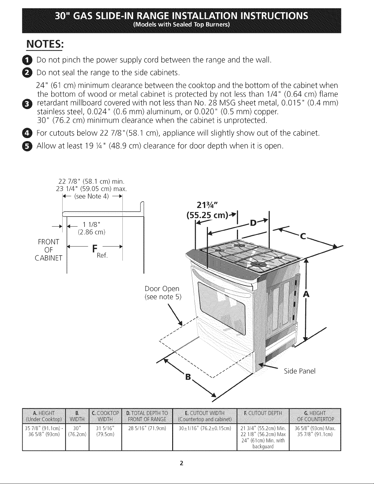
22
7/8"
(58.1
cm)
min.
23
1/4"
(59.05
cm)
max.
-
(see
Note
4)
—
i
2174"
(55.25
cm)*|
>
—y
ee
11/8"
(2.86
cm)
FRONT
;
OF
CABINET
Ref.
Door
Open
(see
note
5)
Side
Panel
AL
HEIGHT
C
COOKIOP
| D
IOIAL
DEPTE
IO
E
CUIOUI
WIDIH
FE
CUIOUL
DEPTH
G
HEGHI
(Under
re
“on
WIDla
FRONT
OF
RANGE
a
anc
ceabinel)
OF
COUNTERTOP
1.9cm)
35
7/8"
28
5/16
'
(76.2+0.15cm)
1
3/4"
(55.2cm)
Min.
36
5/8"
(93cm)
Max.
36
v8"
‘on
We
Jem)
ia.
te
2
1/8"
ee
sm
Max
35
7/8"
(91.
ie
oa"
(61cm)
Min.
with
backguard
30”
GAS
SLIDE-IN
RANGE
INSTALLATION
INSTRUCTIONS
(Models
with
Sealed
Top
Burners)
important
Notes
to
the
Installer
1.
Read
all
instructions
contained
in
these
installation
instructions
before
installing
range.
2.
Remove
all
packing
material
from
the
oven
compartments
before
connecting
the
gas
and
electrical
supply
to
the
range.
Observe
all
governing
codes
and
ordinances.
Be
sure
to
leave
these
instructions
with
the
consumer.
Note:
For
operation
at
2000
ft.
elevations
above
see
level,
appliance
rating
shall
be
reduced
by
4
percent
for
each
additional
1000
ft.
U1
fe
WwW
important
Note
to
the
Consumer
Keep
these
instructions
with
your
Use
&
Care
Guide
for
future
reference.
IMPORTANT
SAFETY
INSTRUCTIONS
Installation
of
this
range
must
conform
with
local
codes
or,
in
the
absence
of
local
codes,
with
the
National
Fuel
Gas
Code
ANSI
Z223.1/NFPA
.54-latest
edition.
This
range
has
been
design
certified
by
CSA
International.
As
with
any
appliance
using
gas
and
generating
heat,
there
are
certain
safety
precautions
you
should
follow.
You
will
find
them
in
the
Use
and
Care
Guide,
read
it
carefully.
e
Be
sure
your
range
is
installed
and
grounded
properly
by
a
qualified
installer
or
service
technician.
e
This
range
must
be
electrically
grounded
in
accordance
with
local
codes
or,
in
their
absence,
with
the
National
Electrical
Code
ANSI/NFPA
No.
70—latest
edition.
See
Grounding
Instructions.
¢
Before
installing
the
range
in
an
area
covered
with
linoleum
or
any
other
synthetic
floor
covering,
make
sure
the
floor
covering
can
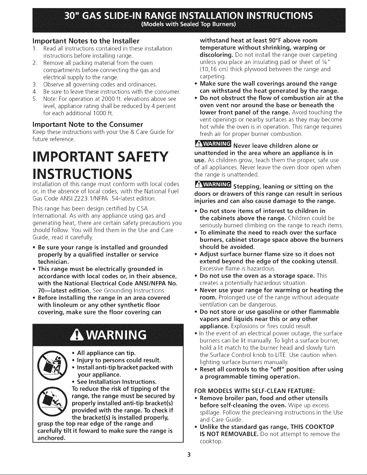
A
WARNING
e
All
appliance
can
tip.
*
Injury
to
persons
could
result.
®
Install
anti-tip
bracket
packed
with
your
appliance.
e
See
Installation
Instructions.
To
reduce
the
risk of
tipping
of
the
range,
the
range
must
be
secured
by
properly
installed
anti-tip
bracket(s)
provided
with
the
range.
To
check
if
the
bracket(s)
is
installed
properly,
grasp
the
top
rear
edge
of
the
range
and
carefully
tilt
it
foward
to
make
sure
the
range
is
anchored.
withstand
heat
at
least
90°F
above
room
temperature
without
shrinking,
warping
or
discoloring.
Do
not
install
the
range
over
carpeting
unless
you
place
an
insulating
pad
or
sheet
of
4"
(10,16
cm)
thick
plywood
between
the
range
and
carpeting.
Make
sure
the wall
coverings
around
the
range
can
withstand
the
heat
generated
by
the
range.
Do
not
obstruct
the
flow
of
combustion
air
at
the
oven
vent
nor
around
the
base
or
beneath
the
lower
front
panel
of
the
range.
Avoid
touching
the
vent
openings
or
nearby
surfaces
as
they
may
become
hot
while
the
oven
is
in
operation.
This
range
requires
fresh
air
for
proper
burner
combustion.
PNWAGIING
Never
leave
children
alone
or
unattended
in
the
area
where
an
appliance
is
in
use.
As
children
grow,
teach
them
the
proper,
safe
use
of
all
appliances.
Never
leave
the
oven door
open
when
the
range
is
unattended.
44
WARNING
Stepping,
leaning
or
sitting
on
the
doors
or
drawers
of
this
range
can
result
in
serious
injuries
and
can
also
cause
damage
to
the
range.
Do
not
store
items
of
interest
to
children
in
the
cabinets
above
the
range.
Children
could
be
seriously
burned
climbing
on the
range
to
reach
items.
To
eliminate
the
need
to
reach
over
the
surface
burners,
cabinet
storage
space
above
the
burners
should
be
avoided.
Adjust
surface
burner
flame
size
so
it
does
not
extend
beyond
the
edge
of
the
cooking
utensil.
Excessive
flame
is
hazardous.
Do
not use
the
oven
as
a
storage
space.
This
creates
a
potentially
hazardous
situation.
Never
use
your
range
for
warming
or
heating
the
room.
Prolonged
use
of
the
range
without
adequate
ventilation
can
be
dangerous.
Do
not
store
or
use
gasoline
or
other
flammable
vapors
and
liquids
near
this
or
any
other
appliance.
Explosions
or
fires
could
result.
In
the
event
of
an
electrical
power
outage,
the
surface
burners
can
be
lit
manually.
To
light
a
surface
burner,
hold
a
lit
match
to
the
burner
head
and
slowly
turn
the
Surface
Control
knob
to
LITE.
Use
caution
when
lighting
surface
burners
manually.
Reset
all
controls
to
the
"off"
position
after
using
a
programmable
timing
operation.
FOR
MODELS
WITH
SELF-CLEAN
FEATURE:
Remove
broiler
pan,
food
and
other
utensils
before
self-cleaning
the
oven.
Wipe
up
excess
spillage.
Follow
the
precleaning
instructions
in
the
Use
and
Care
Guide.
Unlike
the
standard
gas
range,
THIS
COOKTOP
iS
NOT
REMOVABLE.
Do
not
attempt
to
remove
the
cooktop.
30"
GAS
SLIDE-IN
RANGE
INSTALLATION
INSTRUCTIONS
(Models
with
Sealed
Top
Burners)
ER
Cabinet
Construction
BE
P!YENUWTEM
10
eliminate
the
risk
of
cabinet
burns
and
fire,
do
not
have
cabinet
storage
space
above
the
range.
If
there
is
cabinet
storage
space
above
range,
reduce
risk
by
installing
a
range
hood
that
projects
horizontally
a
minimum
of
5"
(12.7cm)
beyond
the
bottom
of
the
cabinet.
KE
Countertop
Preparation
®
The
cooktop
sides
of
the
range
fit
over
the
cutout
edge
of
your
countertop.
®
lf
you
have
a
square
finish
(lat)
countertop,
no
countertop
preparation
is
required.
Cooktop
sides
lay
directly
on
edge
of
countertop.
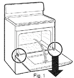
*
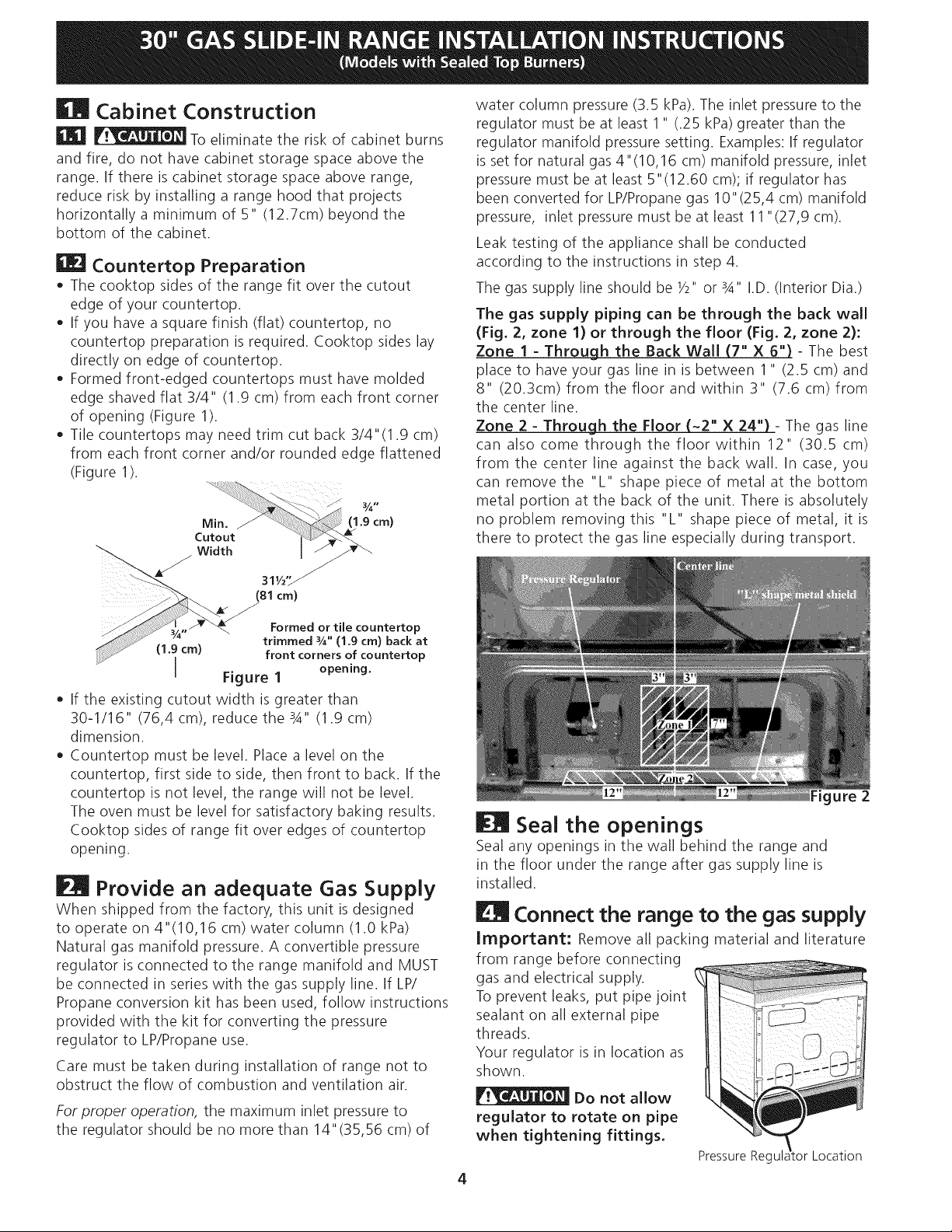
Formed
front-edged
countertops
must
have
molded
edge
shaved
flat
3/4"
(1.9
cm)
from
each
front
corner
of
opening
(Figure
1).
*
Tile
countertops
may
need
trim
cut
back
3/4"(1.9
cm)
from
each
front
corner
and/or
rounded
edge
flattened
(Figure
1).
Min.
Z
£
cm)
Cutout
Width
Le
oN
31%"
SN
(81
cm)
Formed
or
tile
countertop
trimmed
34"
(1.9
cm)
back
at
front
corners
of
countertop
Figure
1
opening.
®
|f
the
existing
cutout
width
is
greater
than
30-1/16"
(76,4
cm),
reduce
the
34"
(1.9
cm)
dimension.
®
Countertop
must
be
level.
Place
a
level
on the
countertop,
first
side
to
side,
then
front
to
back.
If
the
countertop
is
not
level,
the
range
will
not
be
level.
The
oven
must
be
level for
satisfactory
baking
results.
Cooktop
sides
of
range
fit
over
edges
of
countertop
opening.
i
Provide
an
adequate
Gas
Supply
When
shipped
from
the
factory,
this
unit
is
designed
to
operate
on
4°(10,16
cm)
water
column
(1.0
kPa)
Natural
gas
manifold
pressure.
A
convertible
pressure
regulator
is
connected
to
the
range
manifold
and
MUST
be
connected
in
series
with
the
gas
supply
line.
If
LP/
Propane
conversion
kit
has
been
used,
follow
instructions
provided
with
the
kit
for
converting
the
pressure
regulator
to
LP/Propane
use.
Care
must
be
taken
during
installation
of
range
not
to
obstruct
the
flow
of
combustion
and
ventilation
air.
For
proper
operation,
the
maximum
inlet
pressure
to
the
regulator
should
be
no
more
than
14°(35,56
cm)
of
water
column
pressure
(3.5
kPa).
The
inlet
pressure
to
the
regulator
must
be
at
least
1"
(25
kPa)
greater
than
the
regulator
manifold
pressure
setting.
Examples:
If
regulator
is
set
for
natural
gas
4°(10,16
cm)
manifold
pressure,
inlet
pressure
must
be
at
least
5"(12.60
cm);
if
regulator
has
been
converted
for
LP/Propane
gas
10"(25,4
cm)
manifold
pressure,
inlet
pressure
must
be
at
least
11°
(27,9
cm).
Leak
testing
of
the
appliance
shall
be
conducted
according
to
the
instructions
in
step
4.
The
gas
supply
line
should
be
%"
or
34"
LD.
(Interior
Dia.)
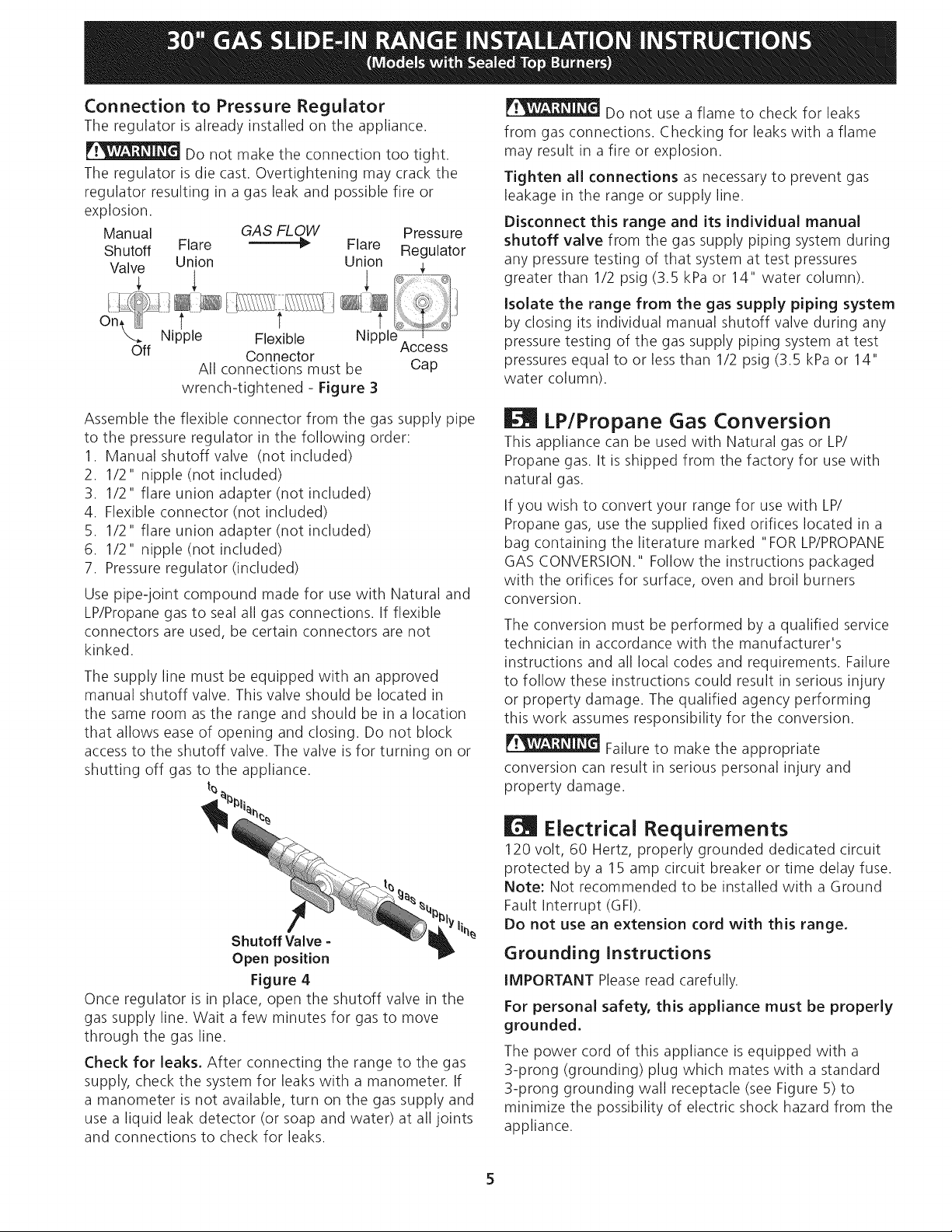
The
gas
supply
piping
can
be
through
the
back
wall
(Fig.
2,
zone
1)
or
through
the
floor
(Fig.
2,
zone
2):
Zone
1
-
Through
the
Back
Wall
(7"
X
6")
-
The
best
place
to
have
your
gas
line
in
is
between
1"
(2.5
cm)
and
8"
(20.3cm)
from
the
floor
and
within
3"
(7.6
cm)
from
the
center
line.
Zone
2
-
Through
the
Floor
~2"
X
24")
-
The
gas
line
can
also
come
through
the
floor
within
12"
(30.5
cm)
from
the
center
line
against
the
back
wall.
In
case,
you
can
remove
the
"L"
shape
piece
of
metal
at
the
bottom
metal portion
at
the
back
of
the
unit.
There
is
absolutely
no
problem
removing
this
"L"
shape
piece
of
metal,
it
is
there
to
protect
the
gas
line
especially
during
transport.
igure
2
EM
Seal
the
openings
Seal
any
openings
in
the
wall
behind
the
range
and
in
the
floor
under
the
range
after
gas
supply
line
is
installed.
Connect
the
range
to
the
gas
supply
Important:
Remove
all
packing
material
and
literature
from
range
before
connecting
gas
and
electrical
supply.
To
prevent
leaks,
put
pipe
joint
sealant
on
all
external
pipe
threads.
Your
regulator
is
in
location
as
shown,
re
SOeIN
Do
not
allow
regulator
to
rotate
on
pipe
when
tightening
fittings.
Pressure
Regulator
Location
30”
GAS
SLIDE-IN
RANGE
INSTALLATION
INSTRUCTIONS
(Models
with
Sealed
Top
Burners)
Connection
to
Pressure
Regulator
The
regulator
is
already
installed
on the
appliance.
ONWASININE]
Do
not
make
the
connection
too
tight.
The
regulator
is
die
cast.
Overtightening
may
crack
the
regulator
resulting
in
a
gas
leak
and
possible
fire
or
explosion.
Manual
GAS
FLOW
Pressure
Shutoff
Flare
,
Flare
Regulator
Valve
Union Union
4
:
|
i
LET
\
Nipple
Flexible
Off
Connector
C
All
connections
must
be
ap
wrench-tightened
-
Figure
3
Assemble
the
flexible
connector
from
the
gas
supply
pipe
to
the
pressure
regulator
in
the
following
order:
Manual
shutoff
valve
(not
included)
1/2"
nipple
(not
included)
1/2"
flare
union
adapter
(not
included)
Flexible
connector
(not
included)
1/2"
flare
union
adapter
(not
included)
1/2"
nipple
(not
included)
Pressure
regulator
(included)
SNOMTRBWN>
Use
pipe-joint
compound
made
for
use
with
Natural
and
LP/Propane
gas
to
seal
all
gas
connections.
If
flexible
connectors
are
used,
be
certain
connectors
are
not
kinked.
The
supply
line
must
be
equipped
with
an
approved
manual
shutoff
valve.
This
valve
should
be
located
in
the
same room
as
the
range
and
should
be
in
a
location
that
allows
ease
of
opening
and
closing.
Do
not
block
access
to
the
shutoff
valve.
The
valve
is
for
turning
on
or
shutting
off
gas
to
the
appliance.
to
e”
Shutoff
Valve
-
Open
position
Figure
4
Once
regulator
is
in
place,
open
the
shutoff
valve
in
the
gas
supply
line.
Wait
a
few
minutes
for
gas
to
move
through
the
gas
line.
Check
for
leaks.
After
connecting
the
range
to
the
gas
supply,
check
the
system
for
leaks
with
a
manometer.
If
a
manometer
is
not
available,
turn
on
the
gas
supply
and
use
a
liquid
leak
detector
(or
soap
and
water)
at
all
joints
and
connections
to
check
for
leaks.
ONIN
Do
not
use
a
flame
to
check
for
leaks
from
gas
connections.
Checking
for
leaks
with
a
flame
may
result
in
a
fire
or
explosion.
Tighten
all
connections
as
necessary
to
prevent
gas
leakage
in
the
range
or
supply
line.
Disconnect
this
range
and
its
individual
manual
shutoff
valve
from
the
gas
supply
piping
system
during
any
pressure
testing
of
that
system
at
test
pressures
greater
than
1/2
psig
(3.5
kPa
or
14"
water
column).
isolate
the
range
from
the
gas
supply
piping
system
by
closing
its
individual
manual
shutoff
valve
during
any
pressure
testing
of
the
gas
supply
piping
system
at
test
pressures
equal
to or
less
than
1/2
psig
(3.5
kPa
or
14"
water column).
[EMl
LP/Propane
Gas
Conversion
This
appliance
can
be
used
with
Natural
gas
or
LP/
Propane
gas.
It
is
shipped
from
the
factory
for
use
with
natural
gas.
If
you
wish
to
convert
your
range
for
use
with
LP/
Propane
gas,
use the
supplied
fixed
orifices
located
in
a
bag
containing
the
literature
marked
“FOR
LP/PROPANE
GAS
CONVERSION."
Follow
the
instructions
packaged
with
the
orifices
for
surface,
oven
and
broil
burners
conversion.
The
conversion
must
be
performed
by
a
qualified
service
technician
in
accordance
with
the
manufacturer's
instructions
and
all
local
codes
and
requirements.
Failure
to
follow
these
instructions
could
result
in
serious
injury
or
property
damage.
The
qualified
agency
performing
this
work
assumes
responsibility
for
the
conversion.
PNW
5
siture
to
make
the
appropriate
conversion
can
result
in
serious
personal
injury
and
property
damage.
[Ml
Electrical
Requirements
120
volt,
60
Hertz,
properly
grounded
dedicated
circuit
protected
by
a
15
amp
circuit
breaker
or
time
delay
fuse.
Note:
Not
recommended
to
be
installed
with
a
Ground
Fault
Interrupt
(GFI).
Do
not
use
an
extension
cord
with
this
range.
Grounding
Instructions
IMPORTANT
Please
read
carefully.
For
personal
safety,
this
appliance
must
be
properly
grounded.
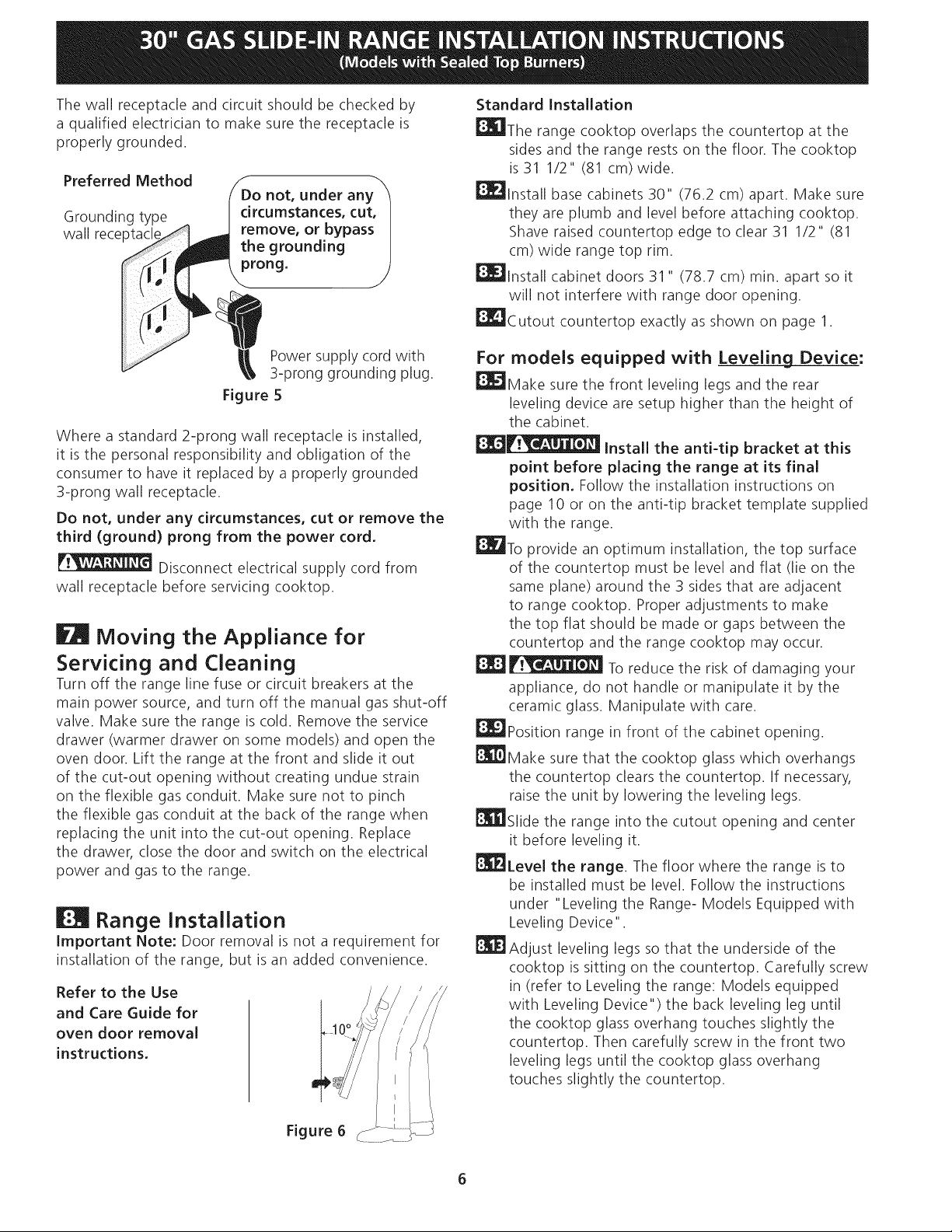
The
power
cord
of
this
appliance
is
equipped
with
a
3-prong
(grounding)
plug
which
mates
with
a
standard
3-prong
grounding
wall
receptacle
(see
Figure
5)
to
minimize
the
possibility
of
electric
shock
hazard
from
the
appliance.
30"
GAS
SLIDE-IN
RANGE
INSTALLATION
INSTRUCTIONS
(Models
with
Sealed
Top
Burners)
The
wail
receptacle
and
circuit
should
be
checked
by
a
qualified
electrician
to
make
sure
the
receptacle
is
properly
grounded.
Preferred
Method
Do
not,
under
any
circumstances,
cut,
remove,
or
bypass
the
grounding
prong.
Grounding
type
wall
receptacle
Power
supply
cord
with
3-prong
grounding
plug.
Figure
5
Where
a
standard
2-prong
wall
receptacie
is
installed,
it
is
the
personal
responsibility
and
obligation
of
the
consumer
to
have
it
replaced
by
a
properly
grounded
3-prong
wail
receptacle.
Do
not,
under
any
circumstances,
cut
or
remove
the
third
(ground)
prong
from
the
power
cord.
NWSI:
Disconnect
electrical
supply
cord
from
wall
receptacle
before
servicing
cooktop.
Moving
the
Appliance
for
Servicing
and
Cleaning
Turn
off
the
range
line
fuse
or
circuit
breakers
at
the
main
power
source,
and
turn
off
the
manual
gas
shut-off
valve.
Make
sure
the
range
is
cold.
Remove
the
service
drawer
(warmer
drawer
on
some
models)
and
open
the
oven
door.
Lift
the
range
at
the
front
and
slide
it
out
of
the
cut-out
opening
without
creating
undue
strain
on the flexible
gas
conduit.
Make
sure
not
to
pinch
the
flexible
gas
conduit
at
the
back
of
the
range
when
replacing
the
unit
into
the
cut-out
opening.
Replace
the
drawer,
close
the
door
and
switch
on
the
electrical
power
and
gas
to
the
range.
EM
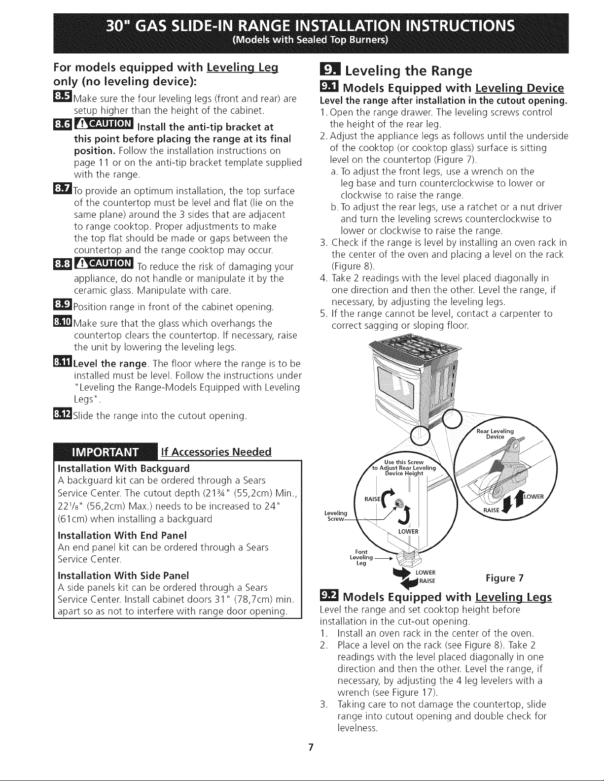
Range
Installation
important
Note:
Door
removal
is
not
a
requirement
for
installation
of
the
range,
but
is
an
added
convenience.
Refer
to
the
Use
and
Care
Guide
for
oven
door
removal
instructions.
Figure
6
Standard
Installation
ES
the
range
cooktop
overlaps
the
countertop
at
the
sides
and
the
range
rests
on the
floor.
The
cooktop
is
31
1/2"
(81
cm)
wide.
EX
install
base
cabinets
30"
(76.2
cm)
apart.
Make
sure
they
are
plumb
and
level
before
attaching
cooktop.
Shave
raised
countertop
edge
to
clear
31
1/2"
(81
cm)
wide
range
top
rim.
EXD
install
cabinet
doors
31"
(78.7
cm)
min.
apart
so
it
will
not
interfere
with
range
door
opening.
ERG
utout
countertop
exactly
as
shown
on
page
1.
For
models
equipped
with
Leveling
Device:
ERI
vake
sure
the
front leveling
legs
and
the
rear
leveling
device
are
setup
higher
than
the
height
of
the
cabinet.
EXS/
Yee
install
the anti-tip
bracket
at
this
point
before
placing
the
range
at
its
final
position.
Follow
the
installation
instructions
on
page
10
or
on the
anti-tip
bracket
template
supplied
with
the
range.
EX
provide
an
optimum
installation,
the
top
surface
of
the
countertop
must
be
level
and
flat
(lie
on the
same
plane)
around
the
3
sides
that
are
adjacent
to
range
cooktop.
Proper
adjustments
to
make
the
top
flat
should
be
made
or
gaps
between
the
countertop
and
the
range
cooktop
may
occur.
To
reduce
the
risk
of
damaging
your
appliance,
do
not
handle
or
manipulate
it
by
the
ceramic
glass.
Manipulate
with
care.
EXD
position
range
in
front
of
the
cabinet
opening.
ERM
Viake
sure that
the
cooktop
glass
which
overhangs
the
countertop
clears
the
countertop.
If
necessary,
raise
the
unit
by
lowering
the
leveling
legs.
ERE
slide
the
range
into
the
cutout
opening
and
center
it
before
leveling
it.
ERP
Level
the
range.
The
floor
where
the
range
is
to
be
installed
must
be
level.
Follow
the
instructions
under
“Leveling
the
Range-
Models
Equipped
with
Leveling
Device".
ERE)
adjust
leveling
legs
so
that
the
underside
of
the
cooktop
is
sitting
on the
countertop.
Carefully
screw
in
(refer
to
Leveling
the
range:
Models
equipped
with
Leveling
Device")
the
back
leveling
leg
until
the
cooktop
glass
overhang
touches
slightly
the
countertop.
Then
carefully
screw
in
the
front
two
leveling
legs
until
the
cooktop
glass
overhang
touches
slightly
the
countertop.
30"
GAS
SLIDE-IN
RANGE
INSTALLATION
INSTRUCTIONS
(Models
with
Sealed
Top
Burners)
For
models
equipped
with
Leveling
Leg
only
(no
leveling
device):
EI
viake
sure
the
four
leveling
legs
(front
and
rear) are
setup
higher
than
the
height
of
the
cabinet.
8.6
Nee
Install
the
anti-tip
bracket
at
this
point
before
placing
the
range
at
its
final
position.
Follow
the
installation
instructions
on
page
11
or
on the
anti-tip
bracket
template
supplied
with
the
range.
Et.
provide
an
optimum
installation,
the
top
surface
of
the
countertop
must
be
level
and
flat
(lie
on
the
same
plane)
around
the
3
sides
that
are
adjacent
to
range
cooktop.
Proper
adjustments
to
make
the
top
flat
should
be
made
or
gaps
between
the
countertop
and
the
range
cooktop
may
occur.
ACAUTION
To
reduce
the
risk
of
damaging
your
appliance,
do
not
handle
or
manipulate
it
by
the
ceramic
glass.
Manipulate
with
care.
ED
position
range
in
front
of
the
cabinet
opening.
ERM
viake
sure that
the glass
which
overhangs
the
countertop
clears
the
countertop.
If
necessary,
raise
the
unit
by
lowering
the
leveling
legs.
ERE
Level
the
range.
The
floor
where
the
range
is
to
be
installed
must
be
level.
Follow
the
instructions
under
“Leveling
the
Range-Models
Equipped
with
Leveling
Legs".
ERY
slide
the
range
into
the
cutout
opening.
IMPORTANT
If
Accessories
Needed
installation
With
Backguard
A
backguard
kit
can
be
ordered
through
a
Sears
Service
Center.
The
cutout
depth
(2134"
(55,2cm)
Min.,
22'/s"
(56,2cm)
Max.)
needs
to
be
increased
to
24"
(61cm)
when
installing
a
backguard
installation
With
End Panel
An
end
panel
kit
can
be
ordered
through
a
Sears
Service
Center.
installation
With
Side
Panel
A
side
panels
kit
can
be
ordered
through
a
Sears
Service
Center.
Install
cabinet
doors
31"
(78,7cm)
min.
apart
so
as
not
to
interfere
with
range
door
opening.
EH
Leveling
the
Range
EX]
Models
Equipped
with
Leveling
Device
Level
the
range
after
installation
in
the
cutout
opening.
1.
Open
the
range
drawer.
The
leveling
screws
control
the
height
of
the
rear
leg.
2.
Adjust
the
appliance
legs
as
follows
until
the
underside
of
the
cooktop
(or
cooktop
glass)
surface
is
sitting
level
on the
countertop
(Figure
7).
a.
To
adjust
the
front
legs,
use
a
wrench
on the
leg
base
and
turn
counterclockwise
to
lower
or
clockwise
to
raise
the
range.
b.
To
adjust
the
rear
legs,
use
a
ratchet
or
a
nut
driver
and
turn
the
leveling
screws
counterclockwise
to
lower
or
clockwise
to
raise
the
range.
3.
Check
if
the
range
is
level
by
installing
an
oven
rack
in
the
center
of
the
oven
and
placing
a
level
on the
rack
(Figure
8).
4.
Take
2
readings
with
the
level
placed
diagonally
in
one
direction
and
then
the
other.
Level the
range,
if
necessary,
by
adjusting
the
leveling
legs.
5.
If
the
range
cannot
be
level,
contact
a
carpenter
to
correct
sagging
or
sloping
floor.
Rear
Levelin
Device
Use
this
Screw
to
Adjust
Rear
Leveling
_
Device
Height
.
Joins
Figure
7
EX]
Models
Equipped
with
Leveling
Legs
Level the
range
and
set
cooktop
height
before
installation
in
the
cut-out
opening.
1.
Install
an
oven
rack
in
the
center
of
the
oven.
2.
Place
a
level
on
the
rack
(see
Figure
8).
Take
2
readings
with
the
level
placed
diagonally
in
one
direction
and
then
the
other.
Level the
range,
if
necessary,
by
adjusting
the
4
leg
levelers
with
a
wrench
(see
Figure
17).
3.
Taking
care
to
not
damage
the
countertop,
slide
range
into
cutout
opening
and
double
check
for
levelness.
30”
GAS
SLIDE-IN
RANGE
INSTALLATION
INSTRUCTIONS
(Models
with
Sealed
Top
Burners)
Et
§
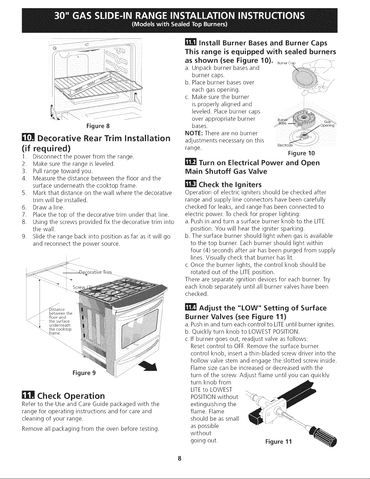
Decorative
Rear
Trim
Installation
(if
required)
1.
Disconnect
the
power
from
the
range.
2.
Make
sure
the
range
is
leveled.
3.
Pull
range
toward
you.
4.
Measure
the
distance
between
the
floor
and
the
surface
underneath
the
cooktop
frame.
5.
Mark
that
distance
on the wall
where
the
decorative
trim
will
be
installed.
Draw
a
line.
Place
the
top
of
the
decorative
trim
under
that
line.
8.
Using
the
screws
provided
fix
the
decorative
trim
into
the
wall.
9.
Slide
the
range
back
into
position
as
far
as
it
will
go
and
reconnect
the
power
source.
OD
_
a
_-
Distance
between
the
floor
and
lo
the
surface
underneath
the
cooktop
frame.
NN
EER
Check
Operation
Refer
to
the
Use
and
Care
Guide
packaged
with
the
range
for
operating
instructions
and
for
care
and
cleaning
of
your
range.
Remove
all
packaging
from
the
oven
before
testing.
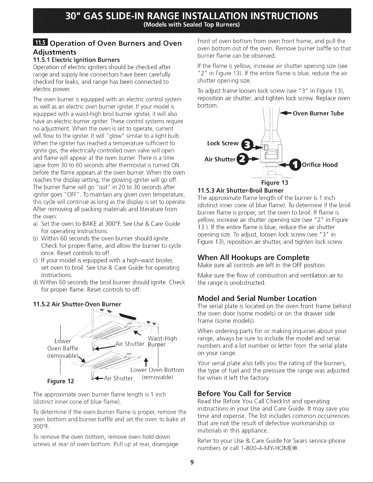
EEA]
install
Burner
Bases
and
Burner
Caps
This
range
is
equipped
with
sealed
burners
as
shown
(see
Figure
10).
aunecap
——
a.
Unpack
burner
bases
and
om
burner
caps.
!
b.
Place
burner
bases
over
Se
each
gas
opening.
ah
c.
Make
sure
the
burner
is
properly
aligned
and
leveled.
Place
burner
caps
over
appropriate
burner
bases.
NOTE:
There
are
no
burner
adjustments
necessary
on
this
range.
")
Electrode
“>-~.
_—_
Figure
10
EEF]
Turn
on
Electrical
Power
and
Open
Main
Shutoff
Gas
Valve
HE]
Check
the
Igniters
Operation
of
electric
igniters
should
be
checked
after
range
and
supply
line
connectors
have
been
carefully
checked
for
leaks,
and
range
has
been
connected
to
electric
power.
To
check
for
proper
lighting:
a.
Push
in
and
turn
a
surface
burner
knob
to
the
LITE
position.
You
will
hear
the
igniter
sparking.
b.
The
surface
burner
should
light
when
qas
is
available
to
the
top
burner.
Each
burner
should
light
within
four
(4)
seconds
after
air
has
been
purged
from
supply
lines.
Visually
check
that
burner
has
lit.
c.
Once
the
burner
lights,
the
control
knob
should
be
rotated
out
of
the
LITE
position.
There
are
separate
ignition
devices
for
each
burner.
Try
each
knob
separately
until
all
burner
valves
have
been
checked.
Adjust
the
"LOW"
Setting
of
Surface
Burner
Valves
(see
Figure
11)
a.
Push
in
and
turn
each
control
to
LITE
until
burner
ignites.
b.
Quickly
turn
knob
to
LOWEST
POSITION.
c.
If
burner
goes
out,
readjust
valve
as
follows:
Reset
control
to
OFF.
Remove
the
surface
burner
control
knob,
insert
a
thin-bladed
screw
driver
into
the
hollow
valve
stem
and
engage
the
slotted
screw
inside.
Flame
size
can
be
increased
or
decreased
with
the
turn
of
the
screw.
Adjust
flame
until
you
can
quickly
turn
knob
from
g
(C
j
LITE
to
LOWEST
POSITION
without
extinguishing
the
flame.
Flame
should
be
as
small
as
possible
without
going
out.
30"
GAS
SLIDE-IN
RANGE
INSTALLATION
INSTRUCTIONS
(Models
with
Sealed
Top
Burners)
EET
Operation
of
Oven
Burners
and
Oven
Adjustments
11.5.1
Electric
Ignition
Burners
Operation
of
electric
igniters
should
be
checked
after
range
and
supply
line
connectors
have
been
carefully
checked
for
leaks,
and
range
has
been
connected
to
electric
power.
The
oven
burner
is
equipped
with
an
electric
control
systern
as
well
as
an
electric
oven
burner
igniter.
ff
your
model
is
equipped
with
a
waist-high
broil
burner
igniter,
it
will
also
have
an
electric
burner
igniter.
These
control
systems
require
no
adjustment.
When
the
oven
is
set
to
operate,
current
will
flow
to
the
igniter.
It
will
"glow"
similar
to
a
light
bulb.
When
the igniter has
reached
a
temperature
sufficient
to
ignite
gas,
the
electrically
controlled
oven
valve
will
open
and
flame
will
appear
at
the
oven
burner.
There
is
a
time
lapse
from
30
to
60
seconds
after
thermostat
is
turned
ON
before
the
flame
appears
at
the
oven
burner.
When
the
oven
reaches
the
display
setting,
the
glowing
igniter
will
go
off.
The
burner
flame
will
go
“out”
in
20
to
30
seconds
after
igniter
goes
"OFF".
To
maintain
any
given
oven
temperature,
this
cycle
will
continue
as
long
as
the
display
is
set
to
operate.
After
removing
all
packing
materials and
literature
from
the
oven:
a)
Set
the
oven
to
BAKE
at
300°F.
See
Use
&
Care
Guide
for
operating
instructions.
b)
Within
60
seconds
the
oven
burner
should
ignite.
Check
for
proper
flame,
and
allow
the
burner
to
cycle
once.
Reset
controls
to
off.
c)
If
your
model
is
equipped
with
a
high-waist
broiler,
set
oven
to
broil.
See
Use
&
Care
Guide
for
operating
instructions.
d)
Within
60
seconds
the
broil
burner
should
ignite.
Check
for
proper
flame. Reset
controls
to
off.
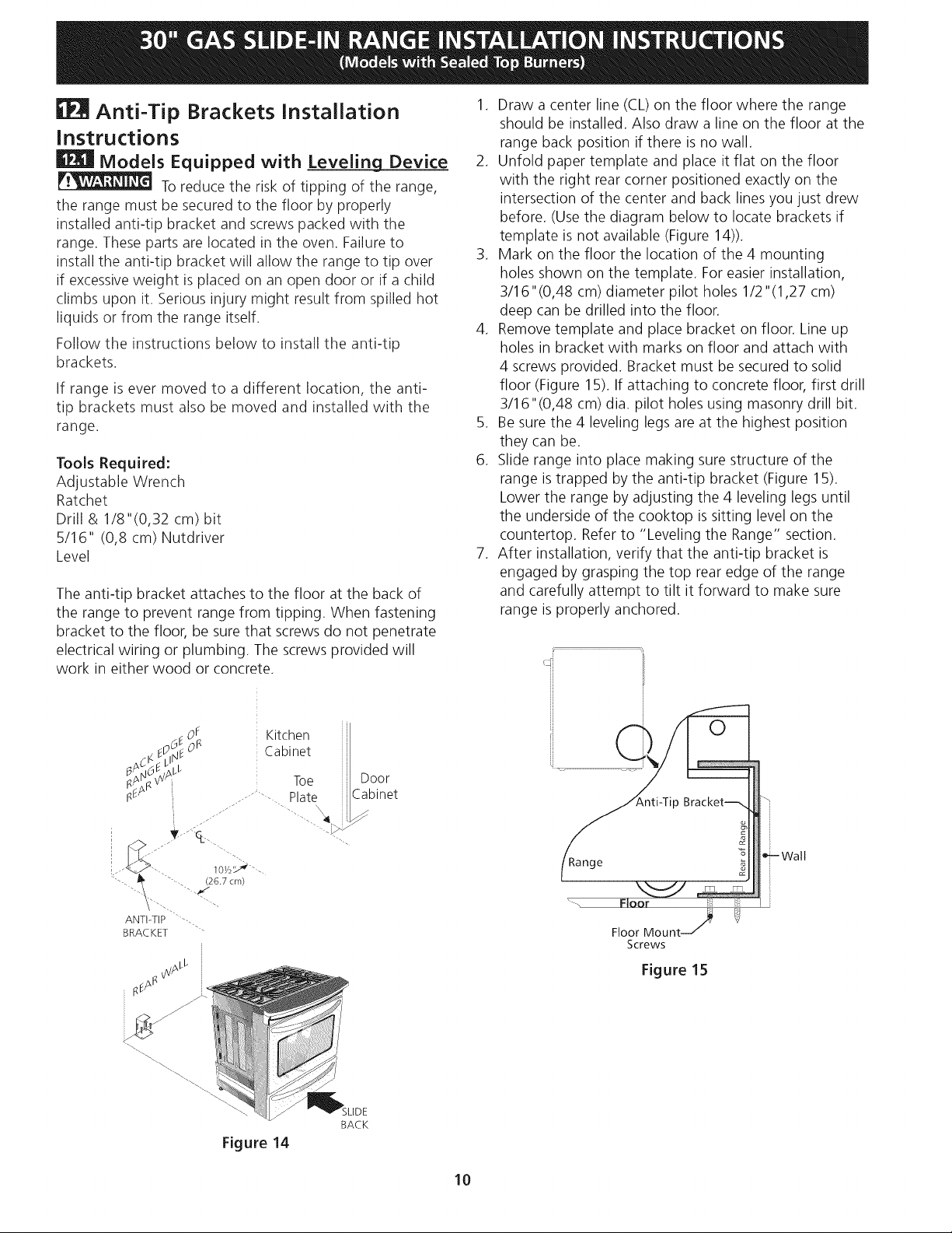
11.5.2
Air
Shutter-Oven
Burner
Wai
Lower”
y
st-High
Oven
Baffle
ur
er
(removable).
.
Cr
Lower
Oven
Bottom
Figure
12
S=Air
Shutter
(removable)
The
approximate
oven
burner
flame
length
is
1
inch
(distinct
inner
cone
of
blue
flame).
To
determine
if
the
oven
burner
flame
is
proper,
remove
the
oven
bottom
and
burner
baffle
and
set
the
oven
to
bake
at
300°F,
To
remove
the
oven
bottom,
remove
oven
hold
down
screws
at
rear
of
oven
bottom.
Pull
up
at
rear,
disengage
front
of
oven
bottom
from
oven
front
frame,
and
pull
the
oven
bottom
out
of
the
oven.
Remove
burner
baffle
so
that
burner
flame
can
be
observed.
if
the
flame
is
yellow,
increase
air
shutter
opening
size
(see
"2"
in
Figure
13).
If
the
entire
flame
is
blue,
reduce
the
air
shutter
opening
size.
To
adjust
frame
loosen
lock
screw
(see
"3"
in
Figure
13),
reposition
air
shutter,
and tighten
lock
screw.
Replace
oven
bottom.
|
|=
Oven
Burner
Tube
Figure
13
11.5.3
Air
Shutter-Broil
Burner
The
approximate
flame
length
of
the
burner
is
1
inch
(distinct
inner
cone
of
blue
flame).
To
determine
if
the
broil
burner
flame
is
proper,
set
the
oven
to
broil.
If
flame
is
yellow,
increase
air
shutter
opening
size
(see
"2"
in
Figure
13
).
If
the
entire
flame
is
blue,
reduce
the
air
shutter
opening
size.
To
adjust,
loosen
lock
screw
(see
"3"
in
Figure
13),
reposition
air
shutter,
and
tighten
lock
screw.
When
All
Hookups
are
Complete
Make
sure
all
controls
are
left
in
the
OFF
position.
Make
sure
the
flow
of
combustion
and
ventilation
air
to
the
range
is
unobstructed.
Model
and
Serial
Number
Location
The
serial
plate
is
located
on the
oven
front
frame
behind
the
oven door
(some
models)
or
on the
drawer
side
frame
(some
models).
When
ordering
parts
for
or
making
inquiries
about
your
range,
always
be
sure
to
include
the
model
and
serial
numbers
and
a
lot
number
or
letter
from
the
serial
plate
on
your
range.
Your
serial
plate
also
tells
you
the
rating
of
the
burners,
the
type
of
fuel
and
the
pressure
the
range
was
adjusted
for
when
it
left
the
factory.
Before
You
Call
for
Service
Read
the
Before
You
Call
Checklist
and
operating
instructions
in
your
Use
and
Care
Guide.
It
may
save
you
time
and
expense.
The
list
includes
common
occurrences
that
are
not
the
result
of
defective
workmanship
or
materials
in
this
appliance.
Refer
to
your
Use
&
Care
Guide
for
Sears
service
phone
numbers
or
call
1-800-4-MY-HOME®.
30"
GAS
SLIDE-IN
RANGE
INSTALLATION
INSTRUCTIONS
(Models
with
Sealed
Top
Burners)
EPA
Anti-Tip
Brackets
Installation
Instructions
EET
Models
Equipped
with
Leveling
Device
AWA
To
reduce
the
risk
of
tipping
of
the
range,
the
range
must
be
secured
to
the
floor
by
properly
installed
anti-tio
bracket
and
screws
packed
with
the
range.
These
parts
are
located
in
the
oven.
Failure
to
install
the
anti-tio
bracket
will
allow
the
range
to
tip
over
if
excessive
weight
is
placed
on
an
open
door
or
if
a
child
climbs
upon
it.
Serious
injury
might
result
from
spilled
hot
liquids
or
from
the
range
itself.
Follow
the
instructions
below
to
install
the
anti-tip
brackets.
If
range
is
ever
moved
to
a
different
location,
the
anti-
tip
brackets
must
also
be
moved
and
installed
with
the
range.
Tools
Required:
Adjustable
Wrench
Ratchet
Drill
&
1/8"(0,32
cm)
bit
5/16"
(0,8
cm)
Nutdriver
Level
The
anti-tip
bracket
attaches
to
the
floor
at
the
back
of
the
range
to
prevent
range
from
tipping.
When
fastening
bracket
to
the
floor,
be
sure
that
screws
do
not
penetrate
electrical
wiring
or
plumbing.
The
screws
provided
will
work
in
either
wood
or
concrete.
of
'
Kitchen
E
2
6
»
Cabinet
Bacae
AL
!
Aas
we
Toe
Door
Ree
|
a
.
Plate
|
Cabinet
weg
Ee
10m
os
we
(26.7
cm)
ANTETIP
>
BRACKET
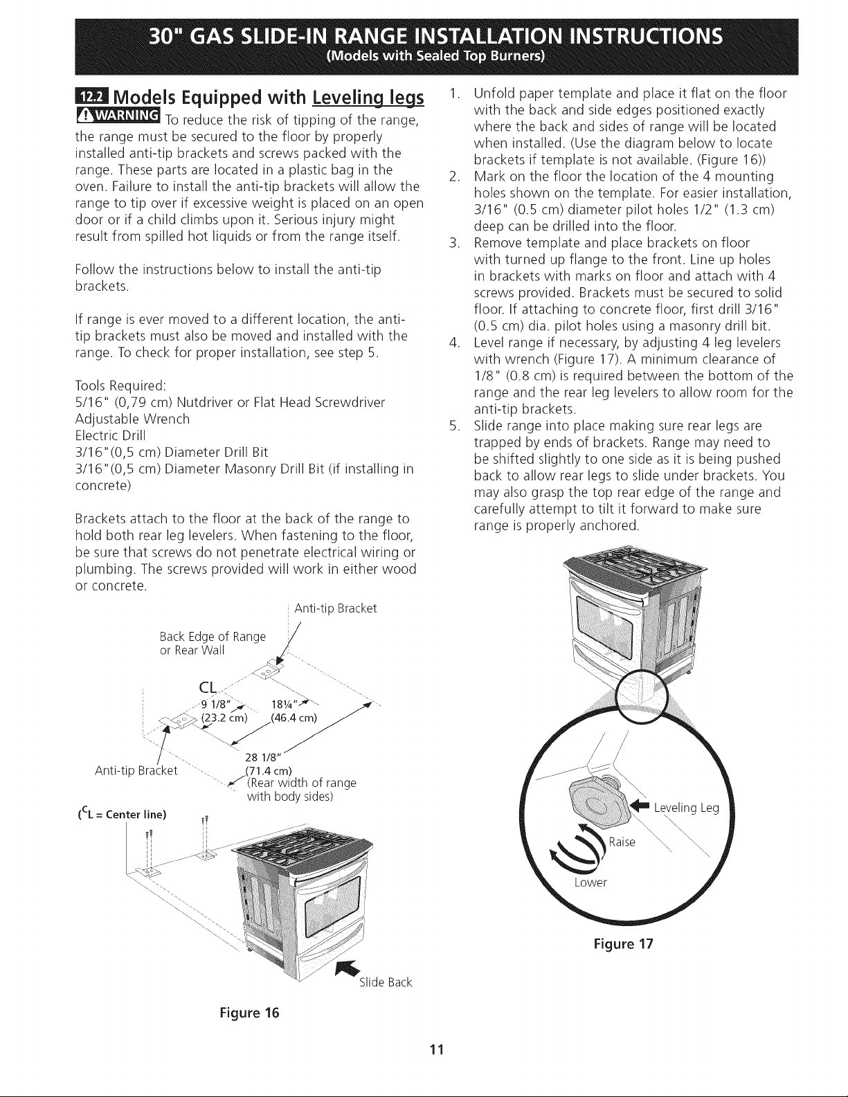
Figure
14
10
.
Draw
a
center
line
(CL)
on
the
floor
where
the
range
should
be
installed.
Also
draw
a
line
on
the
floor
at
the
range
back
position
if
there
is
no
wall.
.
Unfold
paper
template
and
place
it
flat
on
the
floor
with
the
right
rear
corner
positioned
exactly
on
the
intersection
of
the
center
and
back
lines
you
just
drew
before.
(Use
the
diagram
below
to
locate
brackets
if
template
is
not
available
(Figure
14)).
.
Mark
on
the
floor
the
location
of
the
4
mounting
holes
shown
on
the
template.
For
easier
installation,
3/16"(0,48
cm)
diameter
pilot
holes
1/2"(1,27
cm)
deep
can
be
drilled
into
the
floor.
.
Remove
template
and
place
bracket
on
floor.
Line
up
holes
in
bracket
with
marks
on floor
and
attach
with
4
screws
provided. Bracket
must
be
secured
to
solid
floor
(Figure
15).
If
attaching
to
concrete
floor,
first
drill
3/16"(0,48
cm)
dia.
pilot
holes using
masonry
drill
bit.
.
Be
sure
the
4
leveling
legs
are
at
the
highest
position
they
can
be.
.
Slide
range
into
place
making
sure
structure
of
the
range
is
trapped
by
the
anti-tip
bracket
(Figure
15).
Lower
the
range
by
adjusting
the
4
leveling
legs
until
the
underside
of
the
cooktop
is
sitting
level
on
the
countertop.
Refer
to
“Leveling
the
Range”
section.
.
After
installation,
verify
that
the
anti-tip
bracket
is
engaged
by
grasping
the
top
rear
edge
of
the
range
and
carefully
attempt
to
tilt
it
forward
to
make
sure
range
is
properly
anchored.
Anti-Tip
Bracket]
|)
Rear
of
Range
|
e—
Wall
Range
Floor
Floor
Mount
Screws
Figure
15
30"
GAS
SLIDE-IN
RANGE
INSTALLATION
INSTRUCTIONS
(Models
with
Sealed
Top
Burners)
EE2I
Models
Equipped
with
Leveling
legs
ONWAGINING
15
reduce
the
risk
of
tipping
of
the
range,
the
range
must
be
secured
to
the
floor
by
properly
installed
anti-tip
brackets
and
screws
packed
with
the
range.
These
parts
are
located
in
a
plastic
bag
in
the
oven.
Failure
to
install
the
anti-tip
brackets
will
allow
the
range
to
tip
over
if
excessive
weight
is
placed
on
an
open
door
or
if
a
child
climbs
upon
it.
Serious
injury
might
result
from
spilled
hot
liquids
or
from
the
range
itself.
Follow
the
instructions
below
to
install
the
anti-tip
brackets.
If
range
is
ever
moved
to
a
different
location,
the
anti-
tip
brackets
must
also
be
moved
and
installed
with
the
range.
To
check
for
proper
installation,
see
step
5.
Tools
Required:
5/16"
(0,79
cm)
Nutdriver
or
Flat
Head
Screwdriver
Adjustable
Wrench
Electric
Drill
3/16"(0,5
cm)
Diameter
Drill
Bit
3/16"(0,5
cm)
Diameter
Masonry
Drill
Bit
(if
installing
in
concrete)
Brackets
attach
to
the
floor
at
the
back
of
the
range
to
hold
both
rear
leg
levelers.
When
fastening
to
the
floor,
be
sure that
screws
do
not
penetrate
electrical
wiring
or
plumbing.
The
screws
provided
will
work
in
either
wood
or
concrete.
|
Anti-tip
Bracket
Back
Edge
of
Range
or
Rear
Wall
a“
ee
ce
ws,
CL
oN
98"
Se
18a
Gere?
cm)
(46.4
cm)
AL
Ne
a
28
1/8”
Anti-tip
Bracket
>.
(71.4cm)
“2
(Rear
width
of
range
with
body
sides)
Slide
Back
Figure
16
Unfold
paper
template
and
place
it
flat
on the
floor
with
the
back
and
side
edges
positioned
exactly
where
the
back
and
sides
of
range
will
be
located
when
installed.
(Use
the
diagram
below
to
locate
brackets
if
template
is
not
available.
(Figure
16))
Mark
on the
floor
the
location
of
the
4
mounting
holes
shown
on the
template.
For
easier installation,
3/16"
(0.5
cm)
diameter
pilot
holes
1/2"
(1.3
cm)
deep
can
be
drilled
into
the
floor.
Remove
template
and
place
brackets
on floor
with
turned
up
flange
to
the
front.
Line
up
holes
in
brackets
with
marks
on
floor
and
attach
with
4
screws
provided.
Brackets
must
be
secured
to
solid
floor.
If
attaching
to
concrete
floor,
first
drill
3/16"
(0.5
cm)
dia.
pilot
holes using
a
masonry
drill
bit.
Level
range
if
necessary,
by
adjusting
4
leg
levelers
with
wrench
(Figure
17).
A
minimum
clearance
of
1/8"
(0.8
cm)
is
required
between
the
bottom
of
the
range
and
the
rear
leg
levelers
to
allow
room
for
the
anti-tip
brackets.
Slide
range
into
place
making
sure
rear legs
are
trapped
by
ends
of
brackets.
Range
may
need
to
be
shifted
slightly
to
one
side
as
it
is
being
pushed
back
to
allow
rear legs
to
slide
under
brackets.
You
may
also
grasp
the
top
rear
edge
of
the
range
and
carefully
attempt
to
tilt
it
forward
to
make
sure
range
is
properly
anchored.
SS
Lower
Figure
17
INSTRUCCIONES
DE
INSTALACION
DE
COCINAS
DE
GAS
DE
30"
(Modelos
con
quemadores
sellados)
LA
INSTALACION
Y
EL
SERVICIO
DEBEN
SER
EFECTUADOS
POR
UN
INSTALADOR
CALIFICADO.
IMPORTANTE:
GUARDE
ESTAS
INSTRUCCIONES
PARA
USO
DEL
INSPECTOR
LOCAL
DE
ELECTRICIDAD.
LEA
Y
GUARDE
ESTAS
INSTRUCCIONES
PARA
REFERENCIA
FUTURA.
1
VON
EG
ENGEN
Si la
informacién
contenida
en
este
manual
no
es
seguida
exactamente,
puede
ocurrir
un
incendio
o
explosién
causando
dafios
materiales,
lesi6n
personal
o
la
muerte.
PARA
SU
SEGURIDAD:
Aparatos
Instalados
en
el
estado
—
No
almacene
ni
utilice
gasolina
u
otros
vapores
y
liquidos
inflamables
en
la
de
Massachusetts;
proximidad
de
éste
o
de
cualquier
otro
artefacto.
Este
Aparato
sdlo
puede
ser
instalado
—
QUE
DEBE
HACER
SI
PERCIBE
OLOR
A
GAS:
en
el
estado
de
Massachusetts
por
un
*
No
trate
de
encender
ningun
artefacto.
plomero
0
ajustador
de
gas
licenciado
¢
No
toque
ningun
interruptor
eléctrico;
no use
ningtin
teléfono
en
su
edificio.
de
Massachusett.
¢
Llame
a
su
proveedor
de
gas
desde
el
teléfono
de un
vecino.
Siga
las
Este
aparato
se
debe
instalar
con
un
instrucciones
del
proveedor
de
gas.
largo
conector
flexible
de
gas
de
tres
(3)
*
Sino
logra
comunicarse
con
su
proveedor
de
gas,
llame
al
departamento
de
pies/36
pulgadas.
bomberos.
Una
valvula
manual
de
gas
de
tipo
manija
—
La
instalacién
y
el
servicio
de
mantenimiento
deben
ser
efectuados
por
un
de
forma
de "T"
se
debe
instalar
en
la
instalador
calificado,
la
agencia
de
servicio
o
el
proveedor
de
gas.
linea
del
suministro
de
gas
de
este
aparato.
30"
Min.
PARED
|
(76.2
cm
Min.)
La
superficie
debe
——,
|
estar
plana
y
nivelada
(area
sombreada):
oan
30"
Min.
.
1/2"-Min.
(76.2
cm
Min.)
13
Minos?
(véa
la
nota
3)
18"
Min
(33
cm)
Vo"
NAS
(12:7-cm)
de
la-pared;.\
“=
well
(45.7
cm)
Min.
a8:
Wak
ambos.
lados.
6
CM
WidX.
Acepille
el
borde
subido
a
que
_
deje
espacio
L(—<—
a
para
un
borde
_/
31%"
(81
cm)
de
S—<
t
anchura
de
estufa
|
Localice
las
puertas
del
“
armario
1"(2.5
cm)
min
a“
del
hueco
de
la
abertura.
24"
Min.
(61
cm
Min.)
IMPORTANTE:
El
ancho
de
la
cubierta
y
el
armario
debe
de
ser
igual
al
ancho
del
corte.
La
caja
de
empalmes
o
el
enchufe
con
puesta
a
tierra
deberia
situarse
de
8"
a
17"
(20.3
cm
a
43.2
cm)
del
armario
derecho
y
de
2"
a4"
(5.1
cm
a
10.2
cm)
del
suelo.
Wagener
No
instale
la
unidad
en
el
gabinete
si
no
ha
leido
esta
pagina.
A,
ALLURA
B
©.
ANCHO
D.
PROFUNDIDAD
A
EB.
ANCHO
F.
PROFUNDIDAD
De
G,
AURA
DEL
(Under
Cooktop)
DELA
LA
FRENTE
DELA
DE
RECORTADO RECORTADO
MOSTRADOR
PLANCHA
ESIUFA
(Cublerta
y
almario)
DE
COCINAR
35
7/8"
(91.1¢m)
-
"
315/16"
28
5/16"
(71.9cm)
"
21
3/4"
(55.2cm)
Min.
36
5/8"
(93cm)
Max.
36
5/8"
(93cm)
(79.5cm)
.
22
1/8"
(56.2cm)
Max
35
7/8"
(91.1cm)
24"
(61cm)
Min.
with
backquard
NOTA:
Se
adjunta
el
diagrama
de
cables
de
esta
cocina
al
final
de
este
libreta.
P/N
318201681
(0906)
Rev.
A
Impreso
en
los
Estados
Unidos
English
—
pages
1-11;
Espanol
-
paginas
12-23;
Notes
-
pages
24-25;
Diagrama
de
la
instalacién
alambica
-
paginas
26-28
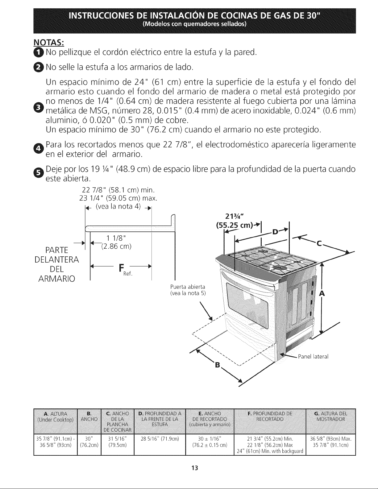
INSTRUCCIONES
DE
INSTALACION
DE
COCINAS
DE
GAS
DE
30"
(Modelos
con
quemadores
sellados)
NOTAS:
@
No
pellizque
el
cordon
eléctrico
entre
la
estufa
y
la
pared.
@)
No
selle
la
estufa
a
los
armarios
de
lado.
Un
espacio
minimo
de
24"
(61
cm)
entre
la
superficie
de
la
estufa
y el
fondo
del
armario
esto
cuando
el
fondo
del
armario
de
madera
o
metal
esta
protegido
por
no
menos
de
1/4“
(0.64
cm)
de
madera
resistente
al
fuego
cubierta
por
una
lamina
9
metdalica
de
MSG,
numero
28,
0.015"
(0.4
mm)
de
acero
inoxidable,
0.024"
(0.6
mm)
aluminio,
6
0.020"
(0.5
mm)
de
cobre.
Un
espacio
minimo
de
30"
(76.2
cm)
cuando
el
armario
no
este
protegido.
Qo
Para
los
recortados
menos
que
22
7/8",
el
electrodoméstico
apareceria
ligeramente
en
el
exterior
del
armario.
e
Deje
por
los
19
4"
(48.9
cm)
de
espacio
libre
para
la
profundidad
de
la
puerta
cuando
este
abierta.
22
7/8"
(58.1
cm)
min.
23
1/4"
(59.05
cm)
max.
«
(veala
nota
4)
»
2134"
i
(55.25
cm)>|
D
sl
1
1/8"
PARTE
(2.86
cm)
DELANTERA
DEL
<<
FT
ARMARIO
,
Puerta
abierta
(vea
la
nota
5)
Panel
lateral
A,
ALIURA
C
ANCHO
D.
PROFUNDIDAD
A
E.
ANCHO
F.
PROFUNDIDAD
DE
G.
ALIURA
DEL
(Under
Cooktop)
DELA
LA
FRENTE
DELA
DE
RECORIADO
RECORIADO
MOSTRADOR
PLANCHA
ESiUA
(Cublerta
y
armario)
DE
COCINAR
35
7/8"
(91.1¢m)
-
36
5/8"
(93cm)
28
5/16"
(71.9cm)
21
3/4"
(55.2cm)
Min.
22
1/8"
(56.2cm)
Max
24"
(61cm)
Min.
with
backquard
36
5/8"
(93cm)
Max.
35
7/8"
(91.1cm)
INSTRUCCIONES
DE
INSTALACION
DE
COCINAS
DE
GAS
DE
30"
(Modelos
con
quemadores
sellados)
Notas
importantes
para
el
Instalador
1.
Lea
todas
las
instrucciones
contenidas
en
este
manual
antes
de
instalar
la
estufa.
Saque
todo
el
material
usado
en
el
embalaje
del
compartimiento
del
horno
antes
de
conectar
el
suministro
eléctrico
o
de
gas
a la
estufa.
Observe
todos
los
cddigos
y
reglamentos
pertinentes.
Deje
estas
instrucciones
con
el
comprador.
Nota:
Para
la
utilizaci6n
a
mas
de
2
000
pies
de altura,
la
potencia
del
aparato
debera
ser
reducida
de
4
por
ciento
a
cada
1
000
pies
adicionales.
wa
eBw
Nota
Importante
para
el
Consumidor
Conserve
estas
instrucciones
y
el
Manual
del
Usuario
para
referencia
futura.
IMPORTANTES
INSTRUCCIONES
DE
SEGURIDAD
Instalacién
de
esta
estufa
debe
cumplir
con
todos
los
cédigos
locales,
o
en
ausencia
de
cddigos
locales
con
el
Cédigo
Nacional
de
Gas
Combustible
ANSI
2223.1/NFPA
.54—ultima
edicidn.
El
disefo
de
esta
estufa
ha
sido
certificado
por
la
CSA
Internacional.
En
éste
como
en
cualquier
otro
artefacto
que
use
gas
y
genere
calor,
hay
ciertas
precauciones
de
seguridad
que
usted
debe
seguir.
Estas
seran
encontradas
en
el
Manual
del
Usuario,
léalo
cuidadosamente.
«
Asegurese
de
que
la
estufa
sea
instalada
y
conectada
a
tierra
en
forma
apropiada
por
un
instalador
calificado
o
por
un
técnico.
¢
Esta
estufa
debe
ser
eléctricamente
puesta
a
tierra
de
acuerdo
con
los
cédigos
locales,
o
en
su
ausencia,
con
el
Cédigo
Eléctrico
Nacional
ANSI/NFPA
No.
70,
ultima
edicién.
Vea
las
instrucciones
para
la
puesta
a
tierra
en
la
pagina
4.
¢
Antes
de
instalar
la
estufa
en
un
area
cuyo
piso
este
recubierto
con
lindleo
u
otro
tipo
de
piso
sintético,
asegurese
de
que
éstos
puedan
resistir
una
temperatura
de
por
lo
menos
90°F
sobre
la
temperatura
ambiental
sin
provocar
encogimiento,
deformacién
o
decoloracién.
No
instale
la
estufa
sobre
una
alfombra
al
AV
ADVERTENCIA
*
Todas
las
estufas
pueden
volcarse.
*
Esto
podria
resultar
en
lesiones
personales.
¢
Instale
el
dispositivo
anti
vuelcos
que
se
ha
empacado
junto
con
esta
estufa.
Para
reducir
el
riesgo
de
que
se
vuelque
la
estufa,
hay
que
asegurarla
adecuadamente
colo
candole
los
soportes
antivuelco
que
se
proporcionan.
Para
comprobar
si
estos
estan
instalados
y
apretados
en
su
lugar
como
se
debe,
ase
el
borde
trasero
superior
de
la
estufa
y
cuidado
samente
incline
la
hacia
adelante
para
asegurar
que
la
estufa
se
ancle.
14
menos
que
cologue
una
plancha
de
material
aislante
de
por
lo
menos
1/4
pulgada,
entre
la
estufa
y
la
alfombra.
«
Asegurese
de
que
el
material
que recubre
las
paredes
alrededor
de
la
estufa,
pueda
resistir
el
calor
generado
por
la
estufa.
¢
No
obstruya
el
flujo
del
aire
de
combustion
en
la
ventilacién
del
horno
ni
tampoco
alrededor
de
la
base
o
debajo
del
panel
inferior
delantero
de
la
estufa.
Evite
tocar
las
aberturas
0
areas
cercanas
de
la
ventilacion,
ya
que
pueden
estar
muy
calientes
durante
el
funcionamiento
del
horno.
La
estufa
requiere
aire
fresco
para
la
combustién
apropiada
de
los
quemadores.
Nunca
deje
nifios
solos
o
desatendidos
en un
area
donde
un
artefacto
esta
siendo
usado.
A
medida
que
los
nifios
crecen,
enséfeles
el
uso
apropiado
y
de
seguridad
para
todos
los
artefactos.
Nunca
deje
la
puerta
del
horno
abierta
cuando
la
estufa
esta
desatendida.
PSSST
no
se
pare,
apoye
o
siente
en
las
puertas
o
cajones
de
esta
estufa
pues
puede
resultar
en
serias
lesiones
y
puede
también
causar
dafio
a la
estufa.
¢
No
almacene
articulos
que
puedan
interesar
a
los
nifios
en
los
gabinetes
sobre
la
estufa.
Los
nifios
pueden
quemarse
seriamente
tratando
de
trepar
ala
estufa
para
alcanzar
estos
articulos.
«
Los
gabinetes
de
almacenamiento
sobre
la
estufa
deben
ser
evitados,
para
eliminar
la
necesidad
de
tener
que
pasar
sobre
los
quemadores
superiores
de
la
estufa
para
llegar
a
ellos.
¢
Ajuste
el
tamafio
de
la
llama
de
los
quemadores
superiores
de
tal
manera
que
ésta
no
sobrepase
el
borde
de
los
utensilios
de
cocinar.
La
llama
excesiva
es
peligrosa.
¢
No
use
el
horno
como
espacio
de
almacenaje.
Esto
creara
una
situaci6n
potencialmente
peligrosa.
¢
Nunca
use
la
estufa
para
calentar
el
cuarto.
El
uso
prolongado
de
la
estufa
sin
la
adecuada
ventilacidn
puede
resultar
peligroso.
¢
No
almacene
ni
utilice
gasolina
u
otros
vapores
y
liquidos
inflamables
en
la
proximidad
de
éste
o
de
cualquier
otro
artefacto
eléctrico.
Puede
provocar
incendio
o
explosidn.
*
En
caso
de
una
interrupcidn
del
servicio
eléctrico,
es
posible
de
encender
los
queradores
de
superficie
a
mano.
Para
encender
un
quemador
de
superficie,
acerque
un
fdsforo
encendido
del
cabezal
del
quernador,
y
gire
delicadamente
el
botén
de
control
de
superficie
a
LITE
(encendido).
Tener
cuidado
al
encender
los
quemadores
a
mano.
¢
Ajuste
todos
los
controles
a la
posiciédn
"OFF"
(apagada)
después
de
haber
hecho
una
operacién
con
tiempo
programado.
PARA
MODELOS
AUTOLIMPIANTES:
¢
Saque
la
asadera,
alimentos
o
cualquier
otro
utensilio
antes
de
usar
el
ciclo
de
autolimpieza
del
horno.
Limpie
todo
exceso
de
derrame
de
alimentos.
Siga
las
instrucciones
de
prelimpiado
en
el
Manual
del
Usuario.
¢
A
diferencia
de
la
gama
estandar
cocinas
de
gas,
ESTA
PLANCHA
DE
COCINA
NO
ES
MOVIBLE.
No
intente
quitar
la
plancha
de
cocina.
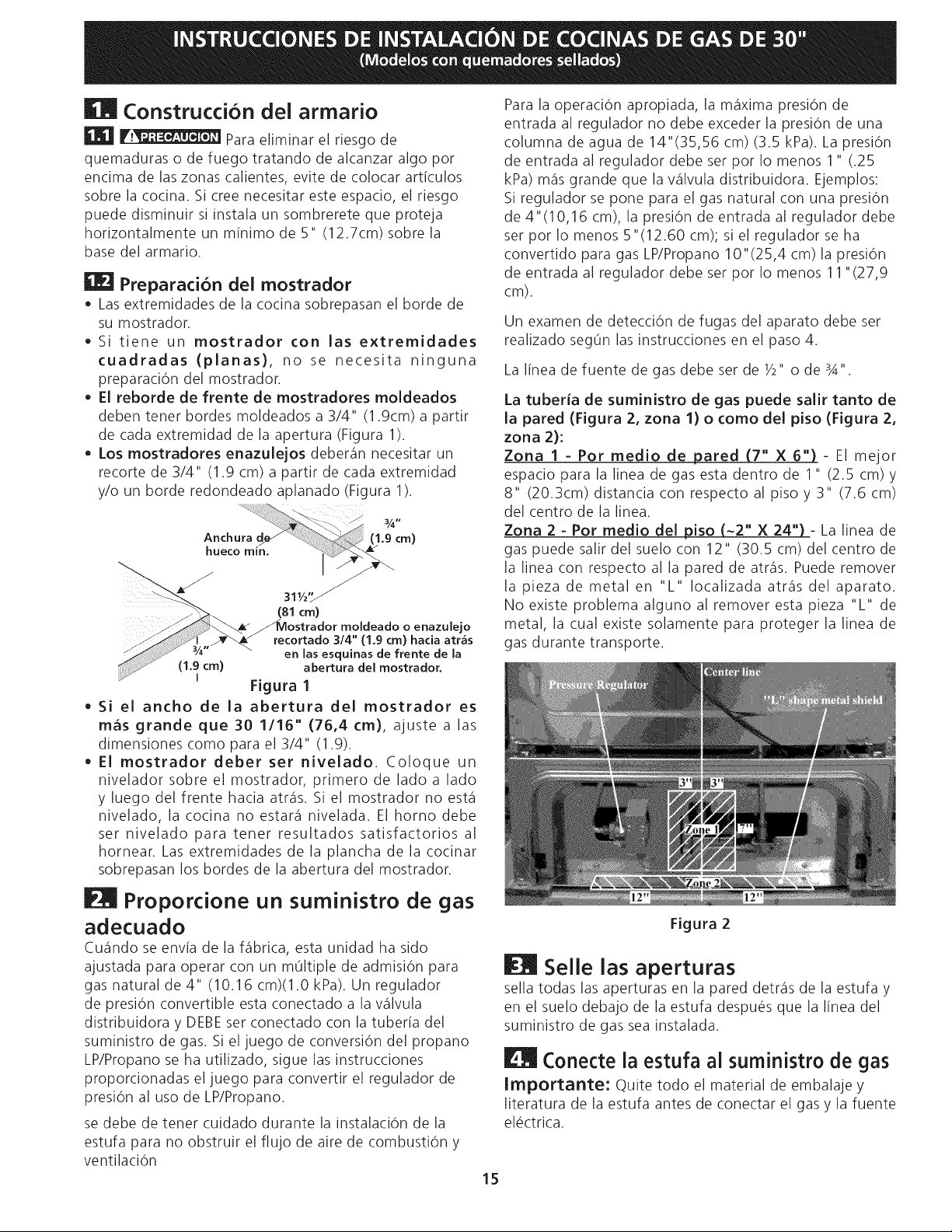
INSTRUCCIONES
DE
INSTALACION
DE
COCINAS
DE
GAS
DE
30"
(Modelos
con
quemadores
sellados)
EM
Construccion
del
armario
ce
Para
eliminar
el
riesgo
de
quemaduras
o
de
fuego
tratando
de
alcanzar
algo
por
encima
de
las
zonas
calientes,
evite de
colocar
articulos
sobre
la
cocina.
Si
cree
necesitar
este
espacio,
el
riesgo
puede
disminuir
si
instala
un
sombrerete
que
proteja
horizontalmente
un
minimo
de
5"
(12.7cm)
sobre
la
base
del
armario.
KEJ
Preparacion
del
mostrador
®
Las
extremidades
de
la
cocina
sobrepasan
el
borde
de
su
mostrador.
e
Si
tlene
un
mostrador
con
las
extremidades
cuadradas
(planas),
no
se
necesita
ninguna
preparacién
del
mostrador.
e
El
reborde
de
frente
de
mostradores
moldeados
deben
tener
bordes
moideados
a
3/4"
(1.9cm)
a
partir
de
cada
extremidad
de
la
apertura
(Figura
1).
e
Los
mostradores
enazulejos
deberan
necesitar
un
recorte
de
3/4"
(1.9
cm)
a
partir
de
cada
extremidad
y/o
un
borde
redondeado
aplanado
(Figura
1).
;
(1.9
cm)
Pe
|
7
ee
(81
cm)
ostrador
moldeado
o
enazulejo
recortado
3/4"
(1.9
cm)
hacia atras
en
las
esquinas
de
frente
de
la
abertura
del
mostrador.
Figura
1
¢
Si el
ancho
de
la
abertura
del
mostrador
es
mas
grande
que
30
1/16"
(76,4
cm),
ajuste
a
las
dimensiones
como
para
el
3/4"
(1.9).
e
El
mostrador
deber
ser
nivelado.
Coloque
un
nivelador
sobre
el
mostrador,
primero
de
lado
a
lado
y
luego
del
frente
hacia
atras.
Si el
mostrador
no
esta
nivelado,
la
cocina
no
estara
nivelada.
El
horno
debe
ser
nivelado
para
tener
resultados
satisfactorios
al
hornear.
Las
extremidades
de
la
plancha
de
la
cocinar
sobrepasan
los
bordes
de
la
abertura
del
mostrador.
hueco
min.
Pi
Proporcione
un
suministro
de
gas
adecuado
Cuando
se
envia
de
la
fabrica,
esta
unidad
ha
sido
ajustada
para
operar
con
un
multiple
de
admision
para
gas
natural
de
4"
(10.16
cm)(1.0
kPa).
Un
requlador
de
presién
convertible
esta
conectado
a
Ja
valvula
distribuidora
y
DEBE
ser
conectado
con
la
tuberia
del
suministro
de
gas.
Si
el
juego
de
conversién
del
propano
LP/Propano
se
ha
utilizado,
sigue
las
instrucciones
proporcionadas
el
juego
para
convertir
el
regulador
de
presién
al
uso
de
LP/Propano.
se
debe
de
tener
cuidado
durante
la
instalacién
de
la
estufa
para
no
obstruir
el
flujo
de
aire
de
combustion
y
ventilacion
15
Para
la
operaciOn
apropiada,
la
maxima
presién
de
entrada
al
requlador
no
debe
exceder
la
presiédn
de
una
columna
de
agua
de
14"(35,56
cm)
(3.5
kPa).
La
presion
de
entrada
al
regulador
debe
ser
por
lo
menos
1"
(.25
KPa)
mas
grande
que
Ja
valvula
distribuidora.
Ejemplos:
Si
regulador
se
pone
para
el
gas
natural
con
una
presién
de
4"(10,16
cm),
la
presidn
de
entrada
al
regulador debe
ser
por
lo
menos
5"(12.60
cm);
si
el
requlador
se
ha
convertido
para
gas
LP/Propano
10"(25,4
cm)
la
presién
de
entrada
al
regulador
debe
ser
por
lo
menos
11°(27,9
cm).
Un
examen
de
deteccién
de
fugas
del
aparato
debe
ser
realizado
segtin
las
instrucciones
en
el
paso
4.
La
linea
de
fuente
de
gas
debe
ser
de
/2"
o
de
A".
La
tuberia
de
suministro
de
gas
puede
salir
tanto
de
la
pared
(Figura
2,
zona
1)
o
como
del
piso
(Figura
2,
zona
2):
Zona
1-
Por
medio
de
pared
(7"_X
6")
-
E|
mejor
espacio
para
la
linea de
gas
esta
dentro
de
1"
(2.5
cm)
y
8"
(20.3cm)
distancia
con
respecto
al
piso
y
3"
(7.6
cm)
del
centro
de
la
linea.
Zona
2
-
Por
medio
del
~2"
X
24"
iso
-
La
linea
de
gas
puede
salir
del
suelo
con
12"
(30.5
cm)
del
centro
de
la
linea
con
respecto
al la
pared
de
atras.
Puede
remover
la
pieza
de
metal
en
“L"
localizada
atrds
del
aparato.
No
existe
problema
alguno
al
remover
esta
pieza
“L"
de
metal,
la
cual
existe
solamente
para
proteger
Ja
linea
de
gas
durante
transporte.
Figura
2
EM
Selle
las
aperturas
sella
todas
las
aperturas
en
la
pared
detras
de
la
estufa
y
en
el
suelo
debajo
de
la
estufa
después
que
la
linea
del
suministro
de
gas
sea
instalada.
Conecte
la
estufa
al
suministro
de
gas
importante:
Quite
todo
el
material
de
embalaje
y
literatura
de
la
estufa
antes
de
conectar
el
gas
y
la
fuente
eléctrica.
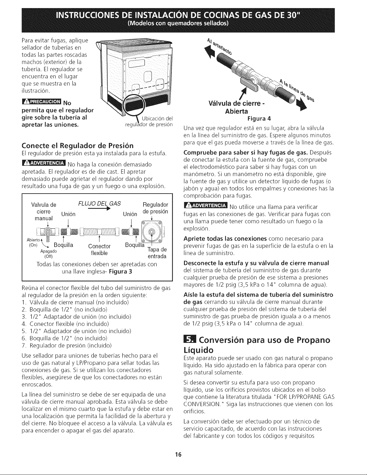
INSTRUCCIONES
DE
INSTALACION
DE
COCINAS
DE
GAS
DE
30"
(Modelos
con
quemadores
sellados)
Para
evitar
fugas,
aplique
sellador
de
tuberfas
en
todas
las
partes
roscadas
machos
(exterior)
de
la
tuberfa.
El
regulador
se
encuentra
en
el
lugar
que
se
muestra
en
la
ilustracion.
No
permita
que
el
regulador
gire
sobre
la
tuberia
al
apretar
las
uniones.
Ubicacion
del
regulador
de
presion
Conecte
el
Regulador
de
Presién
El
requlador
de
presién
esta
ya
instalada
para
la
estufa.
TAMSIN
No
haga
la
conexidn
demasiado
apretada.
El
requlador
es
de
die
cast.
El
apretar
demasiado
puede
agrietar
el
regulador
dando
por
resultado
una
fuga
de
gas
y
un
fuego
o
una
explosion.
Valvula
de
FLUJO
DEL
GAS
Regulador
cierre
we
;
.
de
resign
Unién Unién
p
manual
Ley
|
Abiertoa
|
t
{
eas
(On)
Ne
Boquilla
Conector
Boquilla
Apagado
flexible
Tapa
de
(Off)
entrada
Todas
las
conexiones
deben
ser
apretadas
con
una
llave
inglesa-
Figura
3
Retina
e|
conector
flexible
del
tubo
del
suministro
de
gas
al
regulador
de
la
presién
en
la
orden
siguiente:
Valvula
de
cierre
manual
(no
incluido)
Boquilla
de
1/2" (no
incluido)
1/2"
Adaptador
de
unidn
(no
incluido)
Conector
flexible (no
incluido)
1/2"
Adaptador
de
unidn
(no
incluido)
Boquilla
de
1/2" (no
incluido)
Requlador
de
presién
(inciuido)
SNOMTRBWN>
Use
sellador
para
uniones
de
tuberias
hecho
para
el
uso
de
gas
natural
y
LP/Propano
para
sellar
todas
las
conexiones
de
gas.
Si
se
utilizan
los
conectadores
flexibles,
asequrese
de
que
los
conectadores
no
estan
enroscados.
La
linea
del
suministro
se
debe
de
ser
equipada
de
una
valvula
de
cierre
manual
aprobada.
Esta
valvula
se
debe
localizar
en
el
mismo
cuarto
que
la
estufa
y
debe
estar
en
una
localizacidn
que
permita
la
facilidad
de
la
abertura
y
del
cierre.
No
bloquee
el
acceso
a
la
valvula.
La
valvula
es
para
encender
o
apagar
el
gas
del
aparato.
16
Valvula
de
cierre
-
Abierta
Figura
4
Una
vez
que
regulador
esta
en
su
lugar,
abra
la
valvula
en
la
linea
del
suministro
de
gas.
Espere
algunos
minutos
para
que
el
gas
pueda
moverse
a
través
de
la
linea
de
gas.
Compruebe
para
saber
si
hay
fugas
de
gas.
Después
de
conectar
la
estufa
con
la
fuente
de
gas,
compruebe
el
electrodoméstico
para
saber
si
hay
fugas
con
un
mandometro.
Si
un
mandémetro
no
esta
disponible,
gire
la
fuente
de
gas
y
utilice
un
detector
liquido
de
fugas
(o
jabon
y
aqua)
en
todos
los
empalmes
y
conexiones
has
la
comprobacién
para
fugas.
NSE
No
utilice
una
llama
para
verificar
fugas
en
las
conexiones
de
gas.
Verificar
para
fugas
con
una
llama
puede
tener
como
resultado
un
fuego
o
la
explosion.
Apriete
todas
las
conexiones
como
necesario
para
prevenir
fugas
de
gas
en
la
superficie
de
la
estufa
o
en
la
linea
de
suministro.
Desconecte
la
estufa
y
su
valvula
de
cierre
manual
del
sistema
de
tuberfa
del
suministro
de
gas
durante
cualquier
prueba
de
presién
de
ese
sistema
a
presiones
mayores
de
1/2
psig
(3,5
kPa
o
14"
columna
de
agua).
Aisle
la
estufa
del
sistema
de
tuberia
del
suministro
de
gas
cerrando
su
valvula
de
cierre
manual
durante
cualquier
prueba
de
presién
del
sistema
de
tuberfa
del
suministro
de
gas
prueba
de
presidn
iguala
a
o
a
menos
de
1/2
psig
(3,5
kPa
o
14"
columna
de
agua).
I
conversion
para
uso
de
Propano
Liquido
Este
aparato
puede
ser
usado
con
gas
natural
o
propano
liquido.
Ha sido
ajustado
en
la
fabrica
para
operar
con
gas
natural
solamente.
Si
desea
convertir
su
estufa
para uso
con
propano
iiquido,
use
los
orificios
provistos
ubicados
en
el
bolso
que
contiene
la
literatura
titulada
“FOR
LP/PROPANE
GAS
CONVERSION."
Siga
las
instrucciones
que
vienen
con
los
orificios.
La
conversién
debe
ser
efectuado
por
un
técnico
de
servicio
capacitado,
de
acuerdo
con
las
instrucciones
del
fabricante
y
con
todos
los
cddigos
y
requisitos
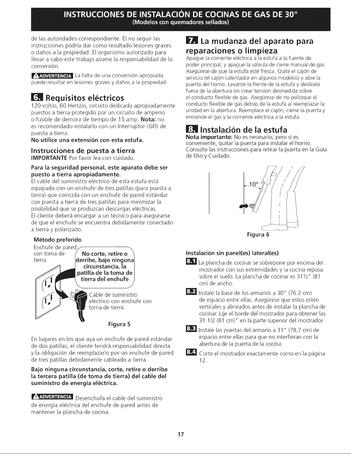
INSTRUCCIONES
DE
INSTALACION
DE
COCINAS
DE
GAS
DE
30"
(Modelos
con
quemadores
sellados)
de
las
autoridades
correspondiente.
El
no
seguir
las
instrucciones
podria
dar
como
resultado
lesiones
graves
o
dafios
a
la
propiedad.
El
organismo
autorizado
para
llevar
a
cabo
este
trabajo
asume
Ja
responsabilidad
de
la
conversion.
7
NeW
aitieye,
La
falta
de
una
conversion
apropiada
puede
resultar
en
lesiones
graves
y
dahos
a
la
propiedad.
[ll
Requisitos
eléctricos
120
voltio,
60
Hertzio,
circuito
dedicado
apropiadamente
puestos
a
tierra
protegido
por
un
circuito
de
amperio
o
fusible
de
demora
de
tiempo
de
15
amp.
Nota:
no
es
recomendado
instalarlo
con
un
Interruptor
(GFI) de
puesta
a
tierra.
No
utilice
una
extensidn
con
esta
estufa.
Instrucciones
de
puesta
a
tierra
IMPORTANTE
Por
favor
lea
con
cuidado.
Para
la
seguridad
personal,
este
aparato
debe
ser
puesto
a
tierra
apropiadamente.
El
cable
del
suministro
eléctrico
de
esta
estufa
esta
equipado
con
un
enchufe
de
tres
patillas
(para
puesta
a
tierra)
que
coincida
con
un
enchufe
de
pared
estandar
con
puesta
a
tierra
de
tres
patillas
para
minimizar
la
posibilidad
que
se
produzcan
descargas
eléctricas.
El
cliente
debera
encargar
a
un
técnico
para
asegurarse
de
que
el
enchufe
se
encuentra
debidamente
conectado
a
tierra
y
polarizado.
Método
preferido
Enchufe
de
pared
con
toma
de
tierra
No
corte,
retire
o
derribe,
bajo
ninguna
circunstancia,
la
patilla
de
la
toma
de
tierra
del
enchufe
g
En
lugares
en
los
que
aya
un
enchufe
de
pared
estandar
de
dos
patillas,
el
cliente
tendra
responsabilidad
directa
y
la
obligacién
de
reemplazarlo
por
un
enchufe
de
pared
de
tres
patillas
debidamente
cableado
a
tierra.
Cable
de
suministro
eléctrico
con
enchufe
con
toma
de
tierra
Figura
5
Bajo
ninguna
circunstancia,
corte,
retire
o
derribe
la
tercera
patilia
(de
toma
de
tierra)
del
cable
del
suministro
de
energia
eléctrica.
VETERAN
pesenchufa
el
cable
del
suministro
de
energia
eléctrica
del
enchufe
de
pared
antes
de
mantener
la
plancha
de
cocina.
7
La
mudanza
del
aparato
para
reparaciones
o
limpieza
Apague
la
corriente
eléctrica
a
la
estufa
a
la
fuente
de
poder
principal,
y
apague
la
valvula
de
cierre
manual
de
gas.
Asegurese
de
que
la
estufa
esté fresca.
Quite
el
cajo6n
de
servicio
(el
cajé6n
calentador
en
algunos
modelos)
y
abre
la
puerta
del
horno.
Levante
la
frente
de
la
estufa
y
deslicela
fuera
de
la
abertura
sin
crear
tensién
desmedida
sobre
el
conducto
flexible
de
gas.
Asegurese
de
no
pellizque
el
conducto
flexible
de
gas
detras
de
la
estufa
al
reemplazar
la
unidad
en
la
abertura.
Reemplace
el
cajén,
cierre
la
puerta
y
enciende
el
gas
y
la
corriente
eléctrica
a
la
estufa.
EW
instalacion
de
la
estufa
Nota
importante:
No
es
necesario,
pero
sf
es
conveniente,
quitar
la
puerta
para
instalar
el
horno.
Consulte
las
instrucciones
para
retirar
la
puerta
en
la
Gula
de
Uso
y
Cuidado.
Instalacién
sin
panel(es)
lateral(es).
Ed
i.
plancha
de
cocinar
se
sobrepone
por
encima
del
mostrador
con
sus
extremidades
y la
cocina
reposa
sobre
el
suelo.
La
plancha
de
cocinar
es
3142"
(81
cm)
de
ancho.
FBZ]
instale
la
base
de
los
armarios
a
30"
(76.2
cm)
de
espacio
entre
ellas.
Aseglirese
que
estos
estén
verticales
y
alineados
antes
de
instalar
la
plancha
de
cocinar.
Lije
el
borde
del
mostrador
para
obtener
las
31
1/2
(81
cm)"
en
la
parte
superior
del
mostrador.
8.3
|
Instale
las
puertas
del
armario
a
31"
(78,7
cm)
de
espacio
entre
ellas
para
que
no
interfieran
con
la
abertura
de
la
puerta
de
la
cocina.
EX
corte
el
mostrador
exactamente
como
en
la
pagina
12.
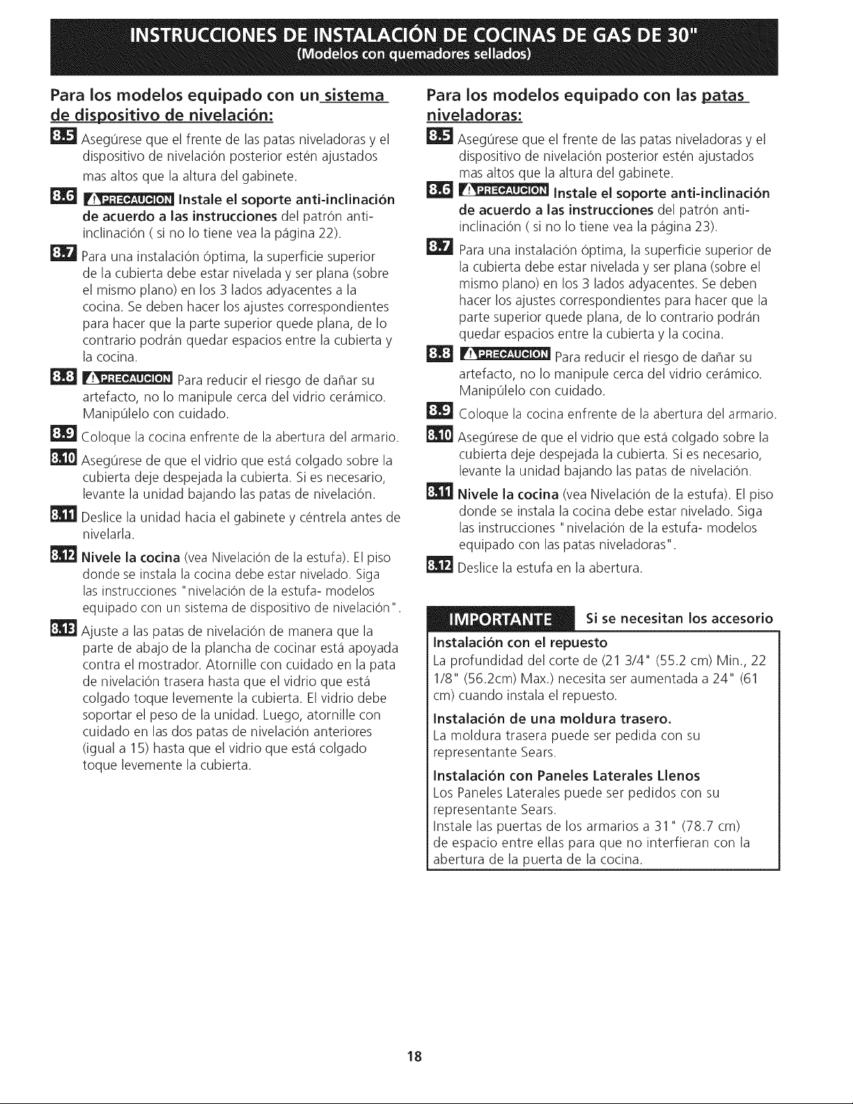
INSTRUCCIONES
DE
INSTALACION
DE
COCINAS
DE
GAS
DE
30"
(Modelos
con
quemadores
sellados)
Para
los
modelos
equipado
con
un_sistema
de
dispositivo
de
nivelacién:
ES
Asegtirese
que
el
frente
de
las
patas
nivelacoras
y
el
dispositivo
de
nivelacién
posterior
estén
ajustados
mas
altos
que
la
altura
del
gabinete.
EG
PENN
instale
el
soporte
anti-inclinacién
de
acuerdo
a
las
instrucciones
cel
patrdn
anti-
inclinacion
(si
no
lo
tiene
vea
la
pagina
22).
EBYd
para
una
instalacion
dptima,
la
superficie
superior
de
la
cubierta
debe
estar
nivelada
y
ser
plana
(sobre
el
mismo
plano)
en
los
3
lados
adyacentes
a
la
cocina.
Se
deben
hacer
los
ajustes
correspondientes
para
hacer
que
la
parte
superior
quede
plana,
de
lo
contrario
podran
quedar
espacios
entre
la
cubierta
y
la
cocina.
Y
NTA
NMTEN
Para
reducir
el
riesgo
de
danar
su
artefacto,
no
lo
manipule
cerca
del
vidrio
ceramico.
Maniptlelo
con
cuidado.
8.9
Coloque
la
cocina
enfrente
de
la
abertura
del
armario.
8.10
Asegtirese
de
que
el
vidrio
que
esta
colgado
sobre
la
cubierta
deje
despejada
la
cubierta.
Si
es
necesario,
levante
la
unidad
bajando
las
patas
de
nivelacion.
ERE]
Destice
la
unidad
hacia
el
gabinete
y
céntrela
antes
de
nivelarla.
ERE)
Nivele
la
cocina
(vea
Nivelacién
de
la
estufa).
El
piso
donde
se
instala
la
cocina
debe
estar
nivelado.
Siga
las
instrucciones
"nivelacién
de
la
estufa-
modelos
equipado
con
un
sistema
de
dispositive
de
nivelacién".
ERE
Ajuste
a
las
patas
de
nivelaci6n
de
manera
que
la
parte
de
abajo
de
la
plancha
de
cocinar
esta
apoyada
contra
el
mostrador.
Atornille
con
cuidado
en
la
pata
de
nivelacién
trasera
hasta
que
el
vidrio
que
esta
colgado
toque
levemente
la
cubierta.
El
vidrio
debe
soportar
el
peso
de
la
unidad.
Luego,
atornille
con
cuidado
en
las
dos
patas
de
nivelacién
anteriores
(igual
a
15)
hasta
que
el
vidrio
que
esta
colgado
toque
levemente
la
cubierta.
18
Para
los
modelos
equipado
con
las
patas
niveladoras:
ES
Asegurese
que
el
frente
de
las
patas
nivelacoras
y
el
dispositivo
de
nivelacién
posterior
estén
ajustados
mas
altos
que
la
altura
del
gabinete.
EG
PNET
instale
el
soporte
anti-inclinacién
de
acuerdo
a
las
instrucciones
cel
patrdn
anti-
inclinacion
(si
no
lo
tiene
vea
la
pagina
23).
EA
para
una
instalacion
optima,
la
superficie
superior
de
la
cubierta
debe
estar
nivelada
y
ser
plana
(sobre
el
mismo
plano)
en
los
3
lados
adyacentes.
Se
deben
hacer
los
ajustes
correspondientes
para
hacer
que
la
parte
superior
quede
plana,
de
lo
contrario
podran
quedar
espacios
entre
la
cubierta
y
la
cocina.
PNET
para
reducir
el
riesgo
de
dafar
su
artefacto,
no
lo
manipule
cerca
del
vidrio
ceramico.
Maniptlelo
con
cuidado.
8.9]
Coloque
la
cocina
enfrente
de
la
abertura
del
armario.
Et
Asegtrese
de
que
el
vidrio
que
esta
colgado
sobre
la
cubierta
deje
despejada
la
cubierta.
Si
es
necesario,
levante
la
unidad
bajando
las
patas
de
nivelacion.
ERE]
Nivele
la
cocina
(vea
Nivelacién
de
la
estufa).
El
piso
donde
se
instala
la
cocina
debe
estar
nivelado.
Siga
las
instrucciones
“nivelacién
de
la
estufa-
modelos
equipado
con
las
patas
niveladoras".
Ey
Deslice
la
estufa
en
la
abertura.
era
pes
Si
se
necesitan
los
accesorio
Instalacién
con
el
repuesto
La
profundidad
del
corte
de
(21
3/4"
(55.2
cm)
Min.,
22
1/8"
(56.2cm)
Max.)
necesita
ser
aumentada
a
24"
(61
cm)
cuando
instala
el
repuesto.
instalaci6n
de
una
moldura
trasero.
La
moldura
trasera
puede
ser
pedida
con
su
representante
Sears.
Instalacidn
con
Paneles
Laterales
Llenos
Los
Paneles
Laterales
puede
ser
pedidos
con
su
representante
Sears.
Instale
las
puertas
de
los
armarios
a
31"
(78.7
cm)
de
espacio
entre
ellas
para
que
no
interfieran
con
la
abertura
de
la
puerta
de
la
cocina.
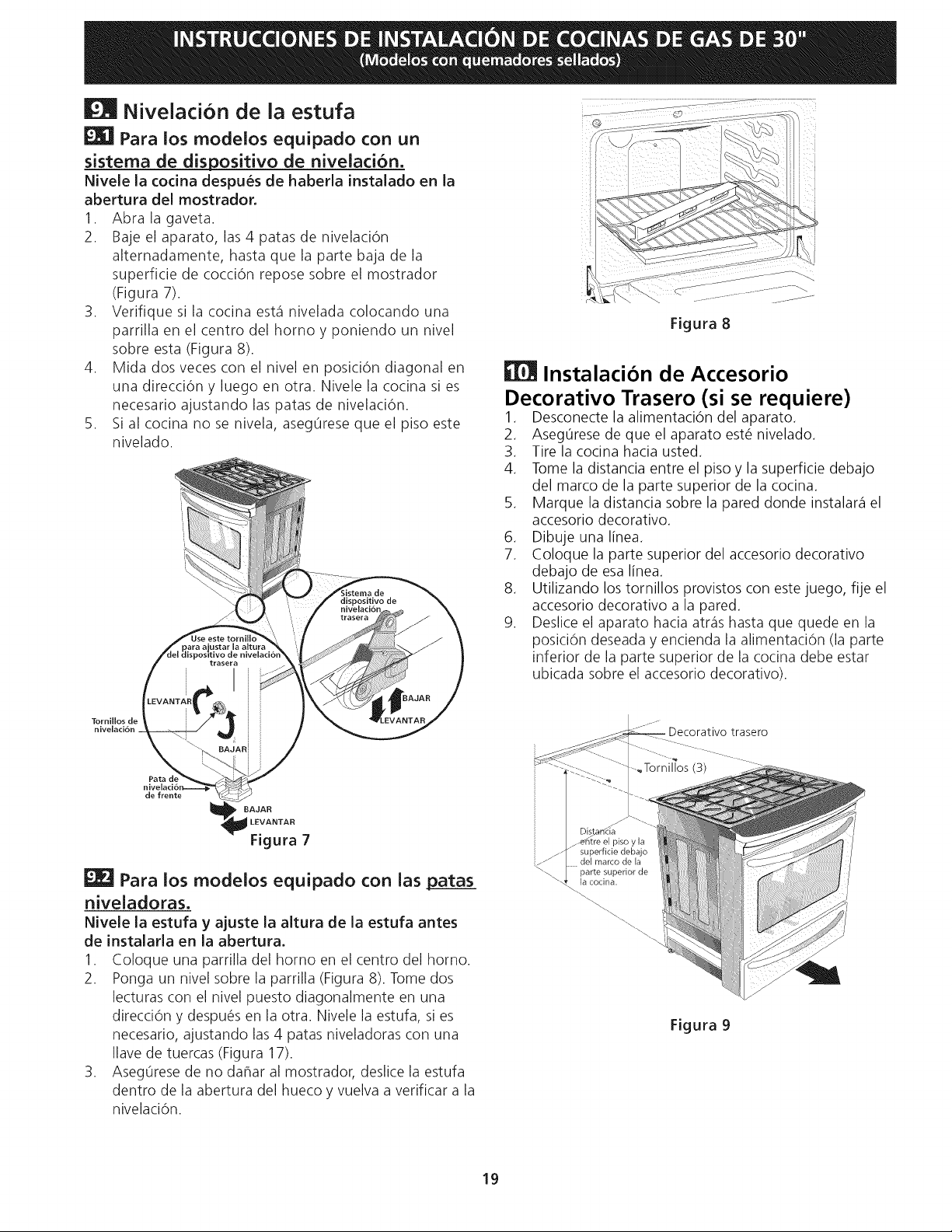
INSTRUCCIONES
DE
INSTALACION
DE
COCINAS
DE
GAS
DE
30"
(Modelos
con
quemadores
sellados)
[MI
Nivelacién
de
la
estufa
EJ
Para
los
modelos
equipado
con
un
sistema
de
dispositivo
de
nivelacion.
Nivele
la
cocina
después
de
haberla
instalado
en
la
abertura
del
mostrador.
1.
2.
Tornillos
de
nivelaci6n
Abra
ja
gaveta.
Baje
el
aparato,
las
4
patas
de
nivelacién
alternadamente,
hasta
que
la
parte
baja
de
la
superficie
de
coccién
repose
sobre
el
mostrador
(Figura
7).
Verifique
si
la
cocina
esta
nivelada
colocando
una
parrilla
en
el
centro
del
horno
y
poniendo
un
nivel
sobre
esta
(Figura
8).
Mida
dos
veces
con
el
nivel
en
posicidn
diagonal
en
una
direccién
y
luego
en
otra.
Nivele
la
cocina
si
es
necesario
ajustando
las
patas
de
nivelacion.
Si
al
cocina
no
se
nivela,
asegtirese
que
el
piso
este
nivelado.
Sistema
de
dispositive
de
nivelacién
Use
este
tornillo
para
ajustar
la
altura
del
dispositive
de
nivelacién
trasera
nivelaci6n__.
de
frente
fe
Kon
LEVANTAR
Figura
7
Ed
Para
los
modelos
equipado
con
las
patas
niveladoras.
Nivele
la
estufa
y
ajuste
la
altura
de
la
estufa
antes
de
instalarla
en
la
abertura.
1.
2.
3.
Cologue
una
parrilla
del
horno
en
el
centro
del
horno.
Ponga
un
nivel
sobre
la
parrilla
(Figura
8).
Tome
dos
lecturas
con
el
nivel
puesto
diagonalmente
en
una
direccidn
y
después
en
la
otra.
Nivele
la
estufa,
si
es
necesario,
ajustando
las 4
patas
niveladoras
con
una
lave
de
tuercas
(Figura
17).
Asegtirese
de
no
dafar
al
mostrador,
desiice
la
estufa
dentro
de
la
abertura
del
hueco
y
vuelva
a
verificar
a
la
nivelacion.
19
Figura
8
EH
Instalacion
de
Accesorio
Decorativo
Trasero
(si
se
requiere)
Desconecte
la
alimentacion
del
aparato.
Asegurese
de
que
el
aparato
esté
nivelado.
Tire
la
cocina
hacia
usted.
Tome
la
distancia
entre
el
piso
y
la
superficie
debajo
del
marco
de
la
parte
superior
de
la
cocina.
5.
Marque
la
distancia
sobre
la
pared
donde
instalara
el
accesorio
decorativo.
Dibuje
una
linea.
Coloque
la
parte
superior
del
accesorio
decorativo
debajo
de
esa
linea.
8.
Utilizando
los
tornillos
provistos
con
este
juego,
fije
el
accesorio
decorativo
a la
pared.
9.
Deslice
el
aparato
hacia
atras
hasta
que
quede
en
la
posicién
deseada
y
encienda
la
alimentacion
(la
parte
inferior
de
la
parte
superior
de
la
cocina
debe
estar
ubicada
sobre
el
accesorio
decorativo).
BWNS
—
Decorativo
trasero
~
~eTornillos
(3)
a
“
Distaricia
_-ehitre
el
piso
y la
/
_-T
superficie
debajo
ao
LL.
del
marco
de
la
NN
parte
superior
de
“¥
la
cocina.
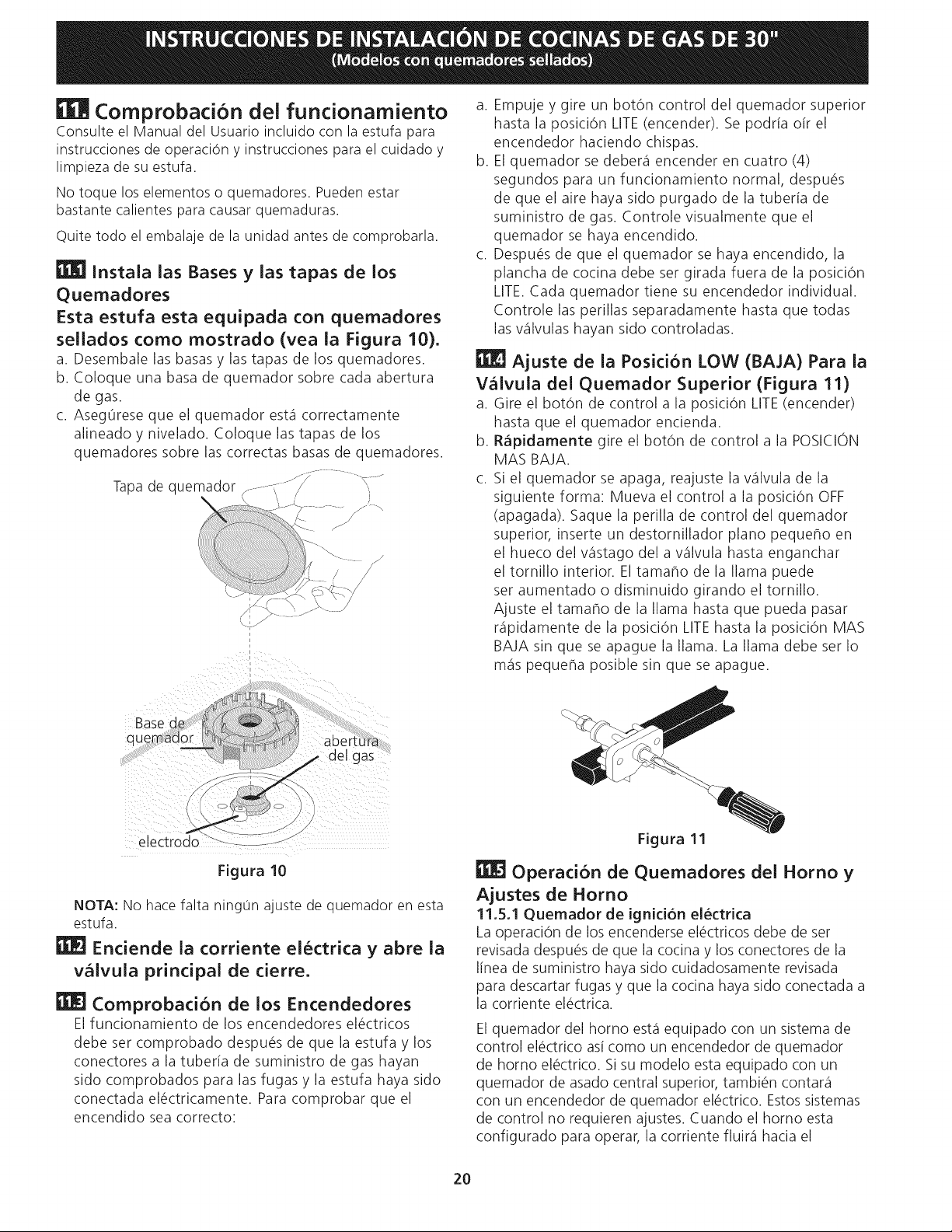
INSTRUCCIONES
DE
INSTALACION
DE
COCINAS
DE
GAS
DE
30"
(Modelos
con
quemadores
sellados)
EEH
Comprobacion
del
funcionamiento
Consulte
el
Manual
del
Usuario
incluido
con
la
estufa
para
instrucciones
de
operacidn
y
instrucciones
para
el
cuidado
y
limpieza
de
su
estufa.
No
toque
los
elementos
o
quemadores.
Pueden
estar
bastante
calientes
para
causar
quemaduras.
Quite
todo
el
embalaje
de
la
unidad
antes
de
comprobarla.
EEE]
instala
las
Bases
y
las
tapas
de
los
Quemadores
Esta
estufa
esta
equipada
con
quemadores
sellados
como
mostrado
(vea
la
Figura
10).
a.
Desembale
las
basas
y
las
tapas
de
los
quemadores.
b.
Coloqgue
una
basa
de
quemador
sobre
cada
abertura
de
gas.
c.
Asegtirese
que
el
quemador
esta
correctamente
alineado
y
nivelado.
Coloque
las
tapas
de
los
quemadores
sobre
las
correctas basas
de
quemadores.
7
Tapa
de
quemador
Base
de
quemador
aberturé
del
gas
"
electrodo
Figura
10
NOTA:
No
hace
falta
ningun
ajuste
de
quemador
en
esta
estufa.
EEF]
Enciende
la
corriente
eléctrica
y
abre
la
valvula
principal
de
cierre.
EEE]
Comprobacién
de
los
Encendedores
El
funcionamiento
de
los
encendedores
eléctricos
debe
ser
comprobado
después
de
que
la
estufa
y
los
conectores
a
la
tuberia
de
suministro
de
gas
hayan
sido
comprobados
para
las
fugas
y
la
estufa
haya
sido
conectada
eléctricamente.
Para
comprobar
que
el
encendido
sea
correcto:
20
a.
Empuje
y
gire
un
botén
control
del
quemador
superior
hasta
la
posici6n
LITE
(encender).
Se
podria
ofr
el
encendedor
haciendo
chispas.
.
El
quemador
se
debera
encender
en
cuatro
(4)
segundos
para
un
funcionamiento
normal,
después
de
que
el
aire
haya
sido
purgado
de
la
tuberfa
de
suministro
de
gas.
Controle
visualmente
que
el
quemador
se
haya
encendido.
c.
Después
de
que
el
quemador
se
haya
encendido,
la
plancha
de
cocina
debe
ser
girada
fuera
de
la
posicién
LITE.
Cada
quemador
tiene
su
encendedor
individual.
Controle
las
perillas
separadamente
hasta
que
todas
las
valvulas
hayan
sido
controladas.
Er
Ajuste
de
la
Posicién
LOW
(BAJA)
Para
la
Valvula
del
Quemador
Superior
(Figura
11)
a.
Gire
el
botén
de
control
a
la
posicién
LITE
(encender)
hasta
que
el
quemador
encienda.
Rapidamente
gire
el
botdn
de
control
a
la
POSICION
MAS
BAJA.
c.
Si
el
quemador
se
apaga,
reajuste
la
valvula
de
la
siguiente
forma:
Mueva
el
control
a
la
posici6n
OFF
(apagada).
Saque
la
perilla
de
control
del
quemador
superior,
inserte
un
destornillador
plano
pequefo
en
el
hueco
del
vastago
del
a
valvula
hasta
enganchar
el
tornillo
interior.
El!
tamafo
de
la
llama
puede
ser
aumentado
o
disminuido
girando
el
tornillo.
Ajuste
el
tamafio
de
la
llama hasta
que
pueda
pasar
rapidamente
de
la
posicién
LITE
hasta
la
posici6n
MAS
BAJA
sin
que
se
apague
la
llama.
La
llama
debe
ser
lo
mas
pequefia
posibie
sin
que
se
apague.
b.
Figura
11
HIE]
Operacion
de
Quemadores
del
Horno
y
Ajustes
de
Horno
11.5.1
Quemador
de
ignicién
eléctrica
La
operacién
de
los
encenderse
eléctricos
debe
de
ser
revisada
después
de
que
la
cocina
y
los
conectores
de
la
linea
de
suministro
haya
sido
cuidadosamente
revisada
para
descartar
fugas
y
que
la
cocina
haya
sido
conectada
a
la
corriente
eléctrica.
El
quemacor
del
horno
esta
equipado
con
un
sistema
de
control
eléctrico
asi
como
un
encendedor
de
quemador
de
horno
eléctrico.
Si
su
modelo
esta
equipado
con
un
quemador
de
asado
central
superior,
también
contara
con
un
encendedor
de
quemador
eléctrico.
Estos
sistemas
de
control
no
requieren
ajustes.
Cuando
el
horno
esta
confiqurado
para
operar,
ja
corriente
fluira
hacia
el
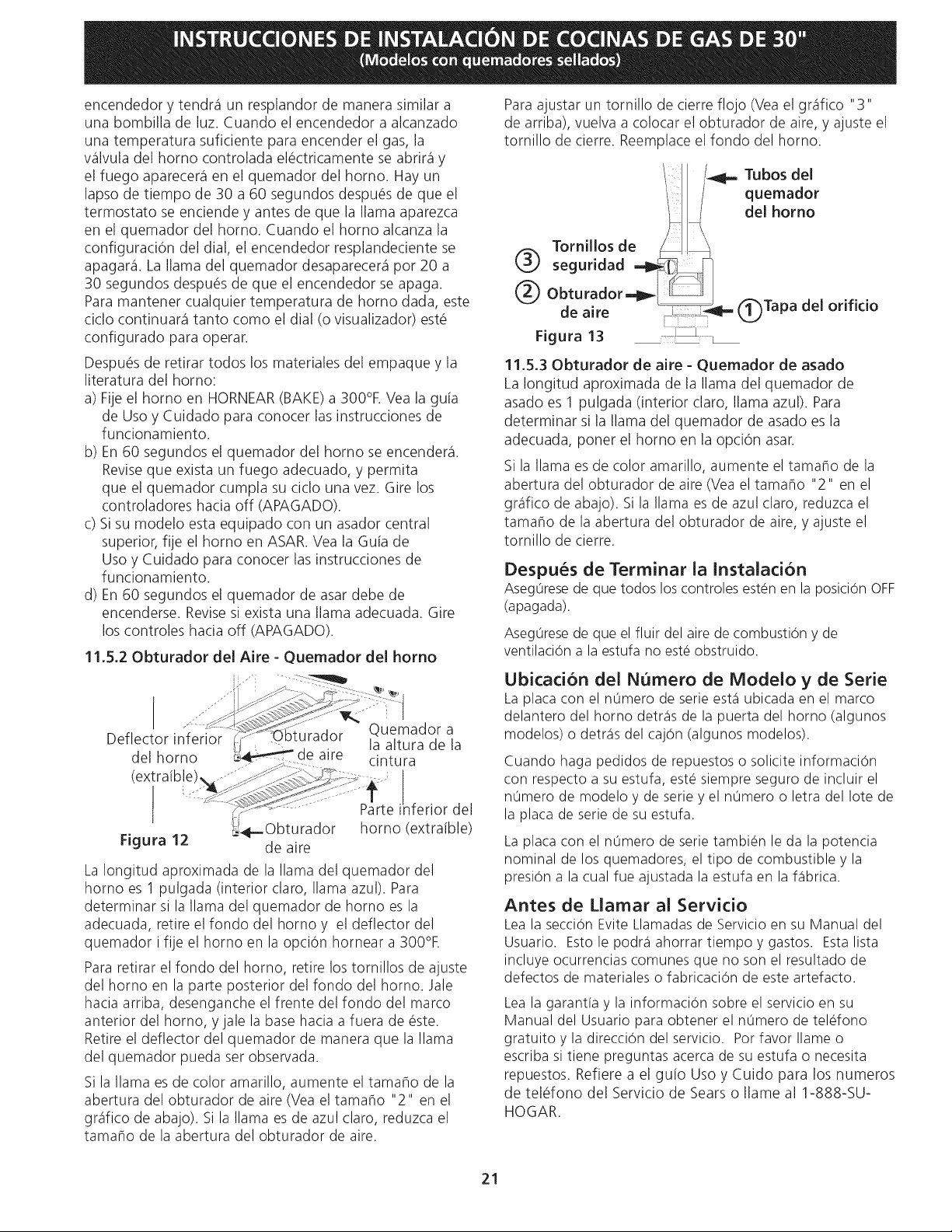
INSTRUCCIONES
DE
INSTALACION
DE
COCINAS
DE
GAS
DE
30"
(Modelos
con
quemadores
sellados)
encendedor
y
tendra
un
resplandor
de
manera
similar
a
una
bombilla
de
luz.
Cuando
el
encendedor
a
alcanzado
una
temperatura
suficiente
para
encender
el
gas,
la
valvula
del
horno
controlada
eléctricamente
se
abrira
y
el
fuego
aparecera
en
el
quemador
del
horno.
Hay
un
lapso
de
tiempo
de
30
a
60
segundos
después
de
que
el
termostato
se
enciende
y
antes
de
que
la
llama
aparezca
en
el
quemador
del
horno.
Cuando
el
horno
alcanza
la
configuracién
del
dial,
el
encendedor
resplandeciente
se
apagara.
La
llama
del
quemador
cesaparecera
por 20
a
30
segundos
después
de
que
el
encendedor
se
apaga.
Para
mantener
cualquier
temperatura
de
horno
dada,
este
ciclo
continuara
tanto
como
el
dial
(0
visualizador)
esté
confiqurado
para
operar.
Después
de
retirar
todos
los
materiales
del
empaque
y
la
literatura
del
horno:
a)
Fije
el
horno
en
HORNEAR
(BAKE)
a
300°F.
Vea
la
guia
de
Uso
y
Cuidado
para
conocer
las
instrucciones
de
funcionamiento.
b)
En
60
segundos
el
quemador
del
horno
se
encendera.
Revise
que
exista
un
fuego
adecuado,
y
permita
que
el
quemador
cumpla
su
ciclo
una
vez.
Gire
los
controladores
hacia
off
(APAGADO).
c)
Sisu
modelo
esta
equipado
con
un
asador
central
superior,
fije
el
horno
en
ASAR.
Vea
la
Gula
de
Uso
y
Cuidado
para
conocer
las
instrucciones
de
funcionamiento.
d)
En
60
segundos
el
quemador
de
asar
debe
de
encenderse.
Revise
si
exista
una
llama
adecuada.
Gire
los
controles
hacia
off
(APAGADO).
11.5.2
Obturador
del
Aire
-
Quemador
del
horno
Deflector
inferior
Cr
“Ob
del
horno
(extrafble)
Quemador
a
la
altura
de
la
cintura
a
EE
ge
|
Parte
inferior
del
horno
(extrafble)
4
bq
Obturador
de
aire
La
longitud
aproximada
de
la
llama
del
quemador
del
horno
es
1
pulgada
(interior
claro,
llama
azul).
Para
determinar
si
la
llama
del
quemador
de
horno
es
la
adecuada,
retire
el
fondo
del
horno
y
el
deflector
del
quemador
i
fije
el
horno
en
la
opcién
hornear
a
300°F.
Figura
12
Para
retirar
el
fondo
del
horno,
retire
los
tornillos
de
ajuste
del
horno
en
la
parte
posterior
del
fondo
del
horno.
Jale
hacia
arriba,
desenganche
el
frente
del
fondo
del
marco
anterior
del
horno,
y
jale
la
base
hacia
a
fuera
de
éste.
Retire
el
deflector
del
quemador
de
manera
que
la
llama
del
quemador
pueda
ser
observada.
Si
la
llama
es
de
color
amarillo,
aumente
el
tamafio
de
la
abertura
del
obturador
de
aire
(Vea
el
tamafio
"2"
en
el
grafico
de
abajo).
Si
la
llama
es
de
azul
claro,
reduzca
e|
tamafio
de
la
abertura
del
obturacor
de
aire.
21
Para
ajustar
un
tornillo
de
cierre
flojo
(Vea
el
grafico
"3"
de
arriba),
vuelva
a
colocar
el
obturador
de
aire,
y
ajuste
e]
tornillo
de
cierre.
Reemplace
el
fondo
del
horno.
\
Lwqx
Tubos
del
\
quemador
del
horno
®
Tornillos
de
__\
seguridad
i
=
(2)
Obturador
=p
[
de
aire
===
(1)
Tapa
del
orificio
Figura
13
a
11.5.3
Obturador
de
aire
-
Quemador
de
asado
La
longitud
aproximada
de
la
llama
del
quemador
de
asado
es
1
pulgada
(interior
claro,
llama
azul).
Para
determinar
si
la
lama
del
quemador
de
asado
es
la
adecuada,
poner
el
horno
en
la
opcién
asar.
Si
la
llama
es
de
color
amarillo,
aumente
el
tamafio
de
la
abertura
del
obturador
de
aire
(Vea
el
tamafio
"2"
en
el
grafico
de
abajo).
Si
la
llama
es
de
azul
claro,
reduzca
el
tamanio
de
la
abertura
del
obturador
de
aire,
y
ajuste
el
tornillo
de
cierre.
Después
de
Terminar
la
Instalacion
Asegurese
de
que
todos
los
controles
estén
en
la
posici6n
OFF
(apagada).
Asegurese
de
que
el
fluir
del
aire
de
combustion
y
de
ventilacién
a
la
estufa
no
esté
obstruido.
Ubicacién
del
Numero
de
Modelo
y
de
Serie
La
placa
con
el
numero
de serie
esta
ubicada
en
el
marco
delantero
del
horno
detras
de
la
puerta
del
horno
(algunos
modelos)
o
detras
del
cajén
(algunos
modelos).
Cuando
haga
pedidos
de
repuestos
o
solicite
informacién
con
respecto
a
su
estufa,
esté
siempre
seguro
de
incluir
el
numero
de
modelo
y
de
serie
y
el
numero
o
letra
del
lote
de
la
placa
de serie
de
su
estufa.
La
placa
con
el
numero
de serie
también
le
da
la
potencia
nominal
de
los
quemadores,
el
tipo
de
combustible
y
la
presion
a
la
cual
fue
ajustada
la
estufa
en
la
fabrica.
Antes
de
Llamar
al
Servicio
Lea
la
seccién
Evite
Llamadas
de
Servicio
en
su
Manual
del
Usuario.
Esto
le
podra
ahorrar
tiempo
y
gastos.
Esta
lista
incluye
ocurrencias
comunes
que
no
son
el
resultado
de
defectos
de
materiales
o
fabricacidn
de
este
artefacto.
Lea
la
garantia
y
la
informacién
sobre
el
servicio
en
su
Manual
del
Usuario
para
obtener
el
numero
de
teléfono
gratuito
y
la
direccién
del
servicio.
Por
favor
llame
o
escriba
si
tiene
preguntas
acerca
de
su
estufa
o
necesita
repuestos.
Refiere
a
el
guio
Uso
y
Cuido
para
los
numeros
de
teléfono
del
Servicio
de
Sears
o
llame
al
1-888-SU-
HOGAR.
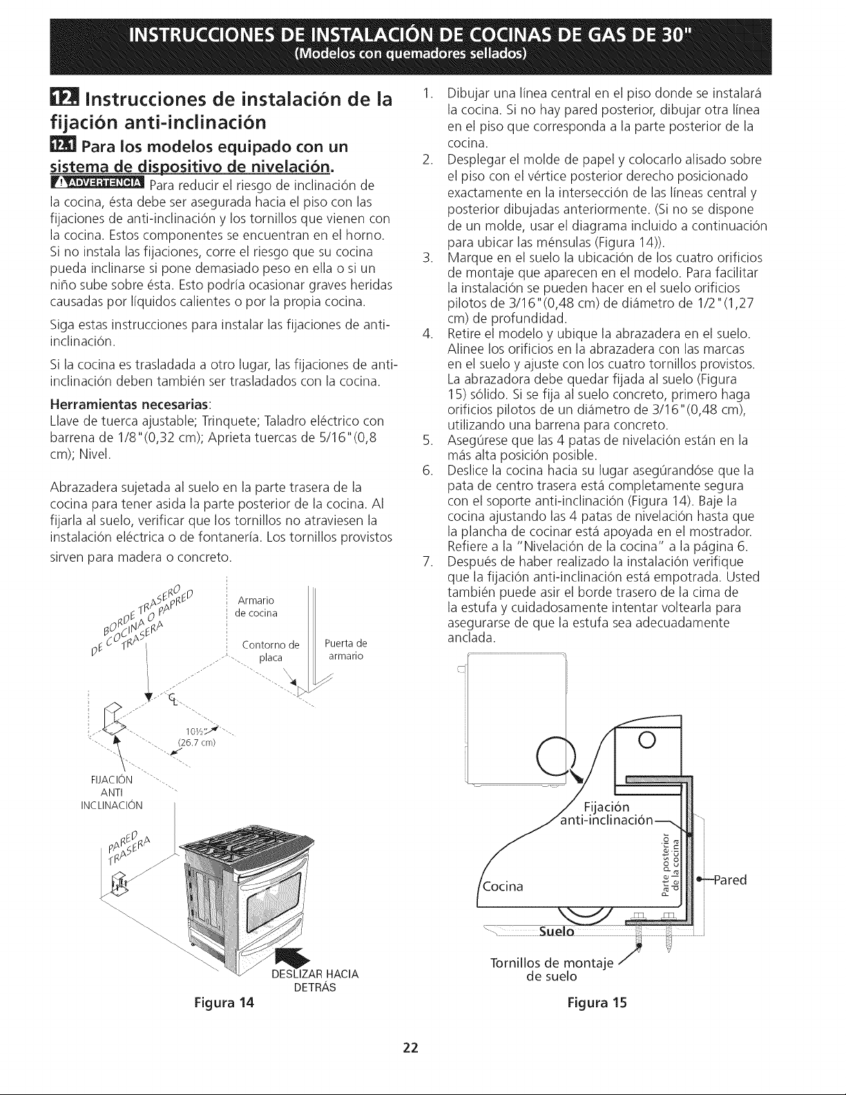
INSTRUCCIONES
DE
INSTALACION
DE
COCINAS
DE
GAS
DE
30"
(Modelos
con
quemadores
sellados)
EPA
instrucciones
de
instalacion
de
la
fijacion
anti-inclinacion
EZ]
Para
los
modelos
equipado
con
un
sistema
de
dispositivo
de
nivelacion.
Para
reducir
el
riesgo
de
inclinacién
de
la
cocina,
ésta
debe
ser
asegurada
hacia
el
piso
con
las
fijaciones
de
anti-inclinacién
y
los
tornillos
que vienen
con
la
cocina.
Estos
componentes
se
encuentran
en
el
horno.
Si
no
instala
las
fijaciones, corre
el
riesgo
que
su
cocina
pueda
inclinarse
si
pone
demasiado
peso
en
ella
o
si
un
nifio
sube
sobre
ésta.
Esto
podria
ocasionar
graves
heridas
causadas
por
liquicdos
calientes
o
por
la
propia
cocina.
Siga
estas
instrucciones
para
instalar
las
fijaciones
de
anti-
inclinacién.
Si
la
cocina
es
trasladada
a
otro
lugar,
las
fijaciones
de
anti-
inclinacién
deben
también
ser
trasladados
con
la
cocina.
Herramientas
necesarias:
Llave
de
tuerca
ajustable;
Trinquete;
Taladro
eléctrico
con
barrena
de
1/8"(0,32
cm);
Aprieta
tuercas
de
5/16"(0,8
cm);
Nivel.
Abrazadera
sujetada
al
suelo
en
la
parte
trasera
de
la
cocina
para
tener
asida
la
parte
posterior
de
la
cocina.
Al
fijarla
al
suelo,
verificar
que
los
tornillos
no
atraviesen
la
instalacion
eléctrica
o
de
fontanerfa.
Los
tornillos
provistos
sirven
para
madera
o
concreto.
O
:
anstpne?
;
Armario
E
T
O
pA
'
de
cocina
A
A
oF
CMR
|
»
Contorno
de
Puerta
de
armario
os
placa
FUACION
ANTI
INCLINACION
DESLIZAR
HACIA
DETRAS
Figura
14
1.
22
Dibujar
una
linea
central
en
el
piso
donde
se
instalara
la
cocina.
Si
no
hay
pared
posterior,
dibujar
otra
linea
en
el
piso
que
corresponda
a
Ja
parte
posterior
de
la
cocina.
Desplegar
el
molde
de
papel
y
colocarlo
alisado
sobre
el
piso
con
el
vértice
posterior
derecho
posicionado
exactamente
en
la
interseccién
de
las
lineas
central
y
posterior
dibujadas
anteriormente.
(Si
no
se
dispone
de un
molde,
usar
el
diagrama
incluido
a
continuacién
para
ubicar
las
ménsulas
(Figura
14)).
Marque
en
el
suelo
la
ubicacién
de
los
cuatro
orificios
de
montaje
que
aparecen
en
el
modelo.
Para
facilitar
la
instalacidn
se
pueden
hacer
en
el
suelo
orificios
pilotos
de
3/16"(0,48
cm)
de
diametro
de
1/2"(1,27
cm)
de
profundidad.
Retire
el
modelo
y
ubique
la
abrazadera
en
el
suelo.
Alinee
los
orificios
en
la
abrazadera
con
las
marcas
en
el
suelo
y
ajuste
con
los
cuatro
tornillos
provistos.
La
abrazadora
debe
quedar
fijada
al
suelo
(Figura
15)
sélido.
Si
se
fija
al
suelo
concreto,
primero
haga
orificios
pilotos
de un
diametro
de
3/16"(0,48
cm),
utilizando
una
barrena
para
concreto.
Aseguirese
que
las 4
patas
de
nivelacién
estan
en
la
mas
alta
posicién
posible.
Deslice
la
cocina
hacia
su
lugar
asequranddse
que
la
pata
de
centro
trasera
esta
completamente
sequra
con
el
soporte
anti-inclinacién
(Figura
14).
Baje
la
cocina
ajustando
las 4
patas
de
nivelacién
hasta
que
la
plancha
de
cocinar
esta
apoyada
en
el
mostrador.
Refiere
a la
“Nivelacién
de
la
cocina”
a
la
pagina
6.
Después
de
haber
realizado
la
instalacién
verifique
que
la
fijacién
anti-inclinacién
esta
empotrada.
Usted
también
puede
asir
el
borde
trasero
de
la
cima
de
la
estufa
y
cuidadosamente
intentar
voltearla
para
asegurarse
de
que
la
estufa
sea
adecuadamente
anclada.
Fijacion
|
anti-inclinacion—\]
Parte
posterior
de
la
cocina
Cocina
Suelo
Tornillos
de
montaje
de
suelo
Figura
15
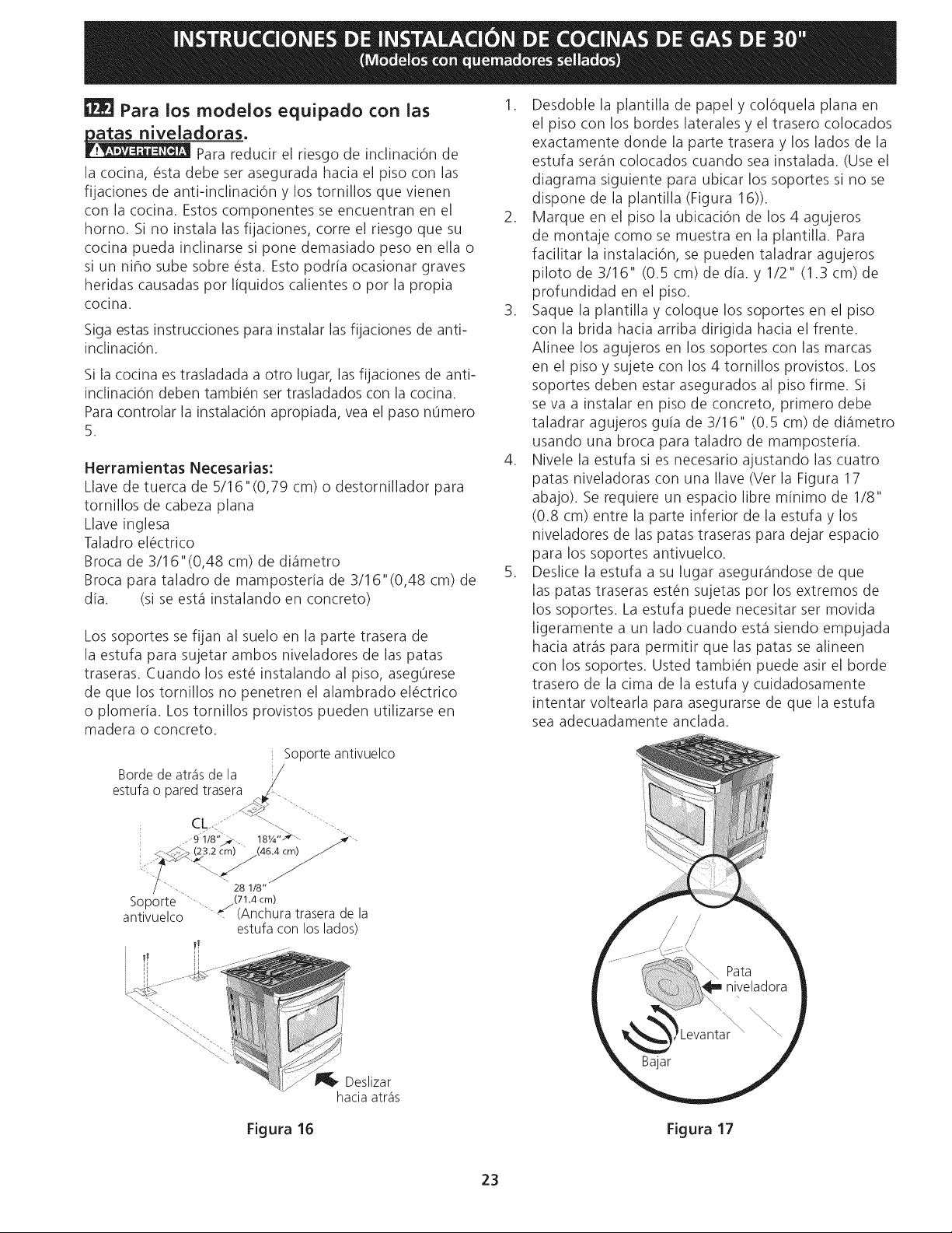
INSTRUCCIONES
DE
INSTALACION
DE
COCINAS
DE
GAS
DE
30"
(Modelos
con
quemadores
sellados)
fh]
Para
los
modelos
equipado
con
las
1.
Desdoble
la
plantilla
de
papel
y
coléquela
plana
en
natas
niveladoras
el
piso
con
los
bordes
laterales
y
el
trasero
colocados
Pieseos
rel
ti de
inclinacion
d
exactamente
donde
la
parte trasera
y
los
lados
de
la
Para
reducir
el
riesgo
de
inclinacion
de
estufa
seran
colocados
cuando
sea
instalada.
(Use
el
la
cocina,
ésta
debe
ser
asegurada
hacia
el
piso
con
las
fiiaciones
de
anti-inclinacién
y
los
tornillos
que
vienen
con
la
cocina.
Estos
componentes
se
encuentran
en
el
2
horno.
Si
no
instala
las
fijaciones,
corre
el
riesqo
que
su
de
montaje
como
se
muestra
en
la
plantilla.
Para
cocina
pueda
inclinarse
si
pone
demasiado
peso
en
ella
o
facilitar
la
instalacion,
se
pueden
taladrar
agujeros
SI
un
nihlo
sube
sobre
esta.
Esto
podria
ocasionar
graves
piloto
de
3/16"
(0.5
cm)
de
dia.
y
1/2"
(1.3.
cm)
de
heridas
causadas
por
liquidos
calientes
o
por
la
propia
profundidad
en
el
piso.
diagrama
siguiente
para
ubicar
los
soportes
si
no
se
dispone
de
la
plantilla
(Figura
16)).
Marque
en
el
piso
la
ubicacién
de
los
4
agujeros
cocina.
3.
Saque
ja
plantilla
y
coloque
los
soportes
en
el
piso
Siga
estas
instrucciones
para
instalar
las
fijaciones
de
anti-
con
la
brida
hacia
arriba
dirigida
hacia
el
frente.
inclinacion.
Alinee
los
agujeros
en
los
soportes
con
las
marcas
; ;
os
;
en
el
piso
y
sujete
con
los
4
tornillos
provistos.
Los
Si
la
cocina
es
trasladada
a
otro
lugar,
las
fijaciones
de
anti-
PISO
y
Su}
P
To
, 7
.
soportes
deben
estar
asegurados
al
piso
firme.
Si
inclinacidn
deben
también
ser
trasladados
con
la
cocina.
p g p
Para
controlar
la
instalaci6n
apropiada,
vea
el
paso
numero
ne
Va
a
instalar
EN
Piso
de
concreto,
primero
debe
5
taladrar
agujeros
quia
de
3/16"
(0.5
cm)
de
diametro
usando
una
broca
para
taladro
de
mamposteria.
4.
Nivele
la
estufa
si
es
necesario
ajustando
las
cuatro
patas
niveladoras
con
una
llave
(Ver
la
Figura
17
abajo).
Se
requiere
un
espacio
libre
minimo
de
1/8"
(0.8
cm)
entre
la
parte
inferior
de
la
estufa
y
los
Herramientas
Necesarias:
Llave
de
tuerca
de
5/16"(0,79
cm)
o
destornillador
para
tornillos
de
cabeza
plana
Llave
inglesa
,
Taladro
eléctrico
niveladores
de
las
patas
traseras
para
dejar
espacio
Broca
de
3/16"(0,48
cm)
de
diametro
5
sch
es
Sopors
antivuelco
sndose
d
Broca
para
taladro
de
mamposteria
de
3/16"
(0,48
cm)
de
7
ESIICE
ta
EStUTa
a
5U
lugar’
asegurandose
de
que
dia.
(si
se
esta
instalando
en
concreto)
las
patas
traseras
estén
sujetas
por
los
extremos
de
los
soportes.
La
estufa
puede
necesitar
ser
movida
ligeramente
a
un
lado
cuando
esta
siendo
empujada
hacia
atras
para
permitir
que
las
patas
se
alineen
con
los
soportes.
Usted
también
puede
asir
el
borde
trasero
de
la
cima
de
Ja
estufa
y
culdadosamente
intentar
voltearla
para
asegurarse
de
que
la
estufa
sea
adecuadamente
anclada.
Los
soportes
se
fijan
al
suelo
en
la
parte trasera
de
ia
estufa
para
sujetar
ambos
niveladores
de
las
patas
traseras.
Cuando
los
esté
instalando
al
piso,
asegurese
de
que
los
tornillos
no
penetren
el
alambrado
eléctrico
o
plomeria.
Los
tornillos
provistos
pueden
utilizarse
en
madera
o
concreto.
Soporte
antivuelco
Borde
de
atras
de
la
estufa
o
pared
trasera
A
Che
ON
SB
GR
gs?
cm)
ma
"28
18"
Soporte
Me
(71.4
cm)
antivuelco
*
(Anchura
trasera
de
la
estufa
con
los
lados)
(46.4
cm)
Bajar
B®
Deslizar
hacia
atras
ll
Figura
16
Figura
17
23

NOTES
-
NOTAS
24

NOTES
-
NOTAS
25
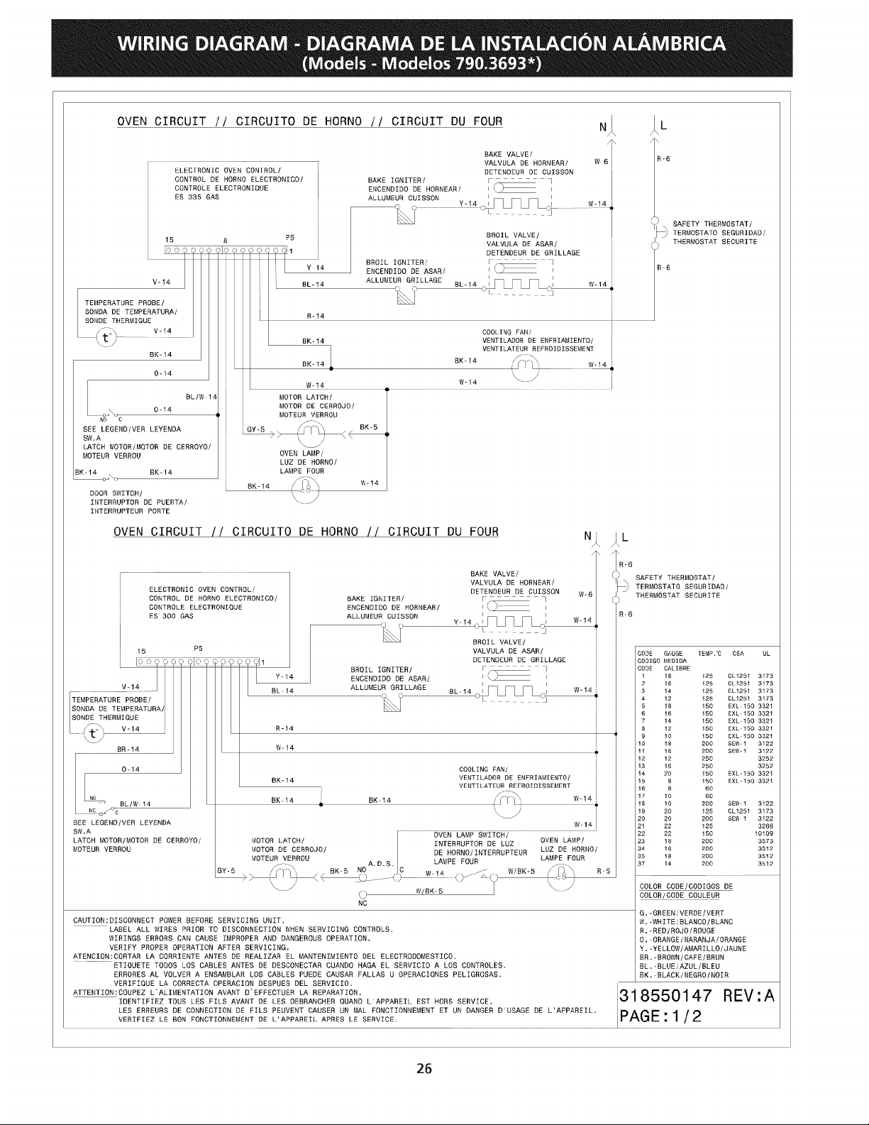
WIRING
DIAGRAM
-
DIAGRAMA
DE
LA
INSTALACION
ALAMBRICA
(Models
-
Modelos
790.3693*)
OVEN
CIRCUIT
//
CIRCUITO
DE
HORNO
//
CIRCUIT
DU
FOUR
BAKE
VALVE/
a6
VALVULA
DE
HORNEAR/
W6
ELECTRONIC
OVEN
CONTROL/
DETENDEUR
DE
CUISSON
CONTROL
DE
HORNO
ELECTRONICO/
BAKE
IGNITER/
mets
CONTROLE
ELECTRONIQUE
ENCENDIDO
DE
HORNEAR/
iO
ES
335 GAS
ALLUMEUR
CUISSON
| |
~
Y-44
1
|
>.
SAFETY
THERMOSTAT/
BROIL
VALVE/
—)
TERMOSTATO
SEGURIDAD/
15
8
VALVULA
DE
ASAR/
ps,”
THERMOSTAT
SECURITE
ee
STi
ee
oe
eT
DETENDEUR
DE
GRILLAGE
.
BROIL
IGNITER/
ws
R-6
ENCENDIDO
DE
ASAR/
(e———
.
Vet4
BL-14
ALLUMEUR
GRILLAGE
BL-14
LPL
Lo
W414
KA
oO
oT
LT
-
7
oF
TEMPERATURE
PROBE/
IN
SONDA
DE
TEMPERATURA/
R14
SONDE
THERMIQUE
coN
vet4
COOLING
FAN/
tv,
—_—_
BK-14
VENTILADOR
DE
ENFRIAMIENTO/
~
VENTILATEUR
REFROIDISSEMENT
BK-
14
mt
BK-14
BK-14
LTS
wei4
0-14
JL
we14
W-14
-
BL/W-14
MOTOR
LATCH/
0-14
MOTOR
DE
CERROJO/
sO
MOTEUR
VERROU
aN
BK-5
SEE
LEGEND/VER
LEYENDA
GY-5
fo
a
>
T
|
b
LATCH
MOTOR/MOTOR
DE
CERROYO/
N_/
MOTEUR
VERROU
OVEN LAMP/
LUZ
DE
HORNO/
BK-14 BK-14
LAMPE
FOUR
“
STL
Wwe14
BK-14
LIAN
:
DOOR
SWITCH/
Ce
INTERRUPTOR
DE
PUERTA/
a
INTERRUPTEUR
PORTE
OVEN
CIRCUIT
//
CIRCUITO
DE
HORNO
//
CIRCUIT
DU
FOUR
N:
Je
A
Tree
BAKE
VALVE/
oO
nue
ORME
(>)
SEE
LMA
ELECTRONIC
OVEN
CONTROL
/
DETENDEUR
DE
CUTSSON
We6
|
7
/
CONTROL
DE
HORNO
ELECTRONICO/
BAKE
IGNITER/
Poo
.
Cy)
THERMOSTAT
SECURITE
CONTROLE
ELECTRONIQUE
ENCENDIDO
DE
HORNEAR/
1-1
ES
300 GAS
ALLUMEUR
CUTSSON
! |
R-6
ners
Y-14...1
al
W-14
K
|
Lo
LL
r
BROIL
VALVE/
VALVULA
DE
ASAR/
CODE
GAUGE
TEMP..C
CSA
UL
DETENDEUR
DE
GRILLAGE
CODIGO
MEDIDA
BROIL
IGNITER/
oT
CODE
CALIBRE
ENCENDIDO
DE
ASAR/
|
Oo
|
1
18
125
CL1251
3173
ALLUMEUR GRILLAGE
| |
2
16
125
CL1251
3173
—_
oO
BL-14
1
a
Wa
3
14
125
CL
1251
3173
TEMPERATURE
PROBE
/
R
J
Te
ee
4
2
125
Ch
izo1
3173
ea
vaeninege
€
16
180
EXL-150
3321
a
7
14
150
EXL-150
3321
(q
oY
V-14 R-14
3
12
150
EXL-180
3324
~~
(t
J
9
10
150
EXL-150
3321
=
16 18
200
SEW:
1
3122
W-14
1
18
200
SEW.
4
3122
12 12
250
3262
13.
16
260
3252
COOLING
FAN?
1420
150
EXL-180
9321
.
VENTILADOR
DE
ENFRIAMIENTO/
= 4
BK-14
18
&
160
EXL.-150
3321
VENTILATEUR
REFROIDISSEMENT
16
8
BO
fom,
.
17 10
60
Bk-14
BK-14
OT
We14
1810
200
©
SeW-1
122
\
ZZ
19
20
125
CL1251
3173
SEE
LEGEND/VER
LEYENDA
~
wet4
a
sO
Sbea
SW.A
OVEN
LAMP
SWITCH
22
22
150
10109
LATCH
MOTOR/MOTOR
DE
CERROYO/
MOTOR
LATGH/
TNTERRUPTOR
DE
Me
OVEN
LAMP/
23
18
200
3573
MOTEUR
VERROU
MOTOR
DE
CERRQJO/
DE
HORNO/INTERRUPTEUR
LUZ
DE
HORNO/
34
16
200
3512
35
13
200
3512
MOTEUR
VERROU
LAMPE
FOUR
LAMPE
FOUR
ey-6
a
aes
wo
2S:
as
37
14
200
4512
Ne
~
W/BK-5
COLOR
CODE/CODIGOS
DE
oO
-
COLOR/CODE
COULEUR
NC
G.
-GREEN/
VERDE
/VERT
CAUTION:
DISCONNECT
POWER
BEFORE
SERVICING
UNIT.
W.
-WHITE
/BLANCO/BLANG
LABEL
ALL
WIRES
PRIOR
TO
DISCONNECTION
WHEN
SERVICING
CONTROLS.
R.
-RED/ROJO/ROUGE
WIRINGS
ERRORS
CAN
CAUSE
IMPROPER
AND
DANGEROUS
OPERATION.
0.
ORANGE
/
NARANJA/
ORANGE
VERIFY
PROPER
OPERATION
AFTER
SERVICING.
Y.-YELLOW/AMARILLO/JAUNE
ATENCION:CORTAR
LA
CORRIENTE
ANTES
DE
REALIZAR
EL
MANTENIMIENTO
DEL
ELECTRODOMESTICO.
BR.
-BROWN/CAFE
/BRUN
ETIQUETE
TODOS
LOS
CABLES ANTES
DE
DESCONECTAR
CUANDO
HAGA
EL
SERVICIO
A
LOS
CONTROLES.
BL.
-BLUE/
AZUL
/BLEU
ERRORES
AL
VOLVER
A
ENSAMBLAR
LOS
CABLES
PUEDE
CAUSAR FALLAS
U
OPERACIONES
PELIGROSAS.
BK.
-BLACK/NEGRO/NOTR
VERIFIQUE
LA
CORRECTA
OPERACION
DESPUES
DEL
SERVICIO.
ATTENTION:
COUPEZ
L‘ALIMENTATION
AVANT
D°EFFECTUER
LA
REPARATION.
IDENTIFIEZ
TOUS
LES
FILS
AVANT
DE
LES
DEBRANCHER
QUAND
L‘APPAREIL
EST
HORS
SERVICE.
LES
ERREURS
DE
CONNECTION
DE
FILS
PEUVENT
CAUSER
UN
MAL
FONCTIONNEMENT
ET
UN
DANGER
D'USAGE
DE
L'APPAREIL.
VERIFIEZ
LE
BON
FONCTIONNEMENT
DE
L’APPAREIL
APRES
LE
SERVICE.
318550147
REV:A
PAGE:
1/2
26
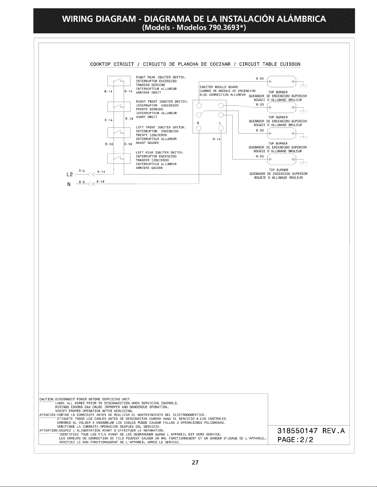
WIRING
DIAGRAM
-
DIAGRAMA
DE
LA
INSTALACION
ALAMBRICA
(Models
-
Modelos
790.3693*)
COOKTOP
CIRCUIT
/
CIRCUITO
DE
PLANCHA
DE
COCINAR
/
CIRCUIT
TABLE
CUISSON
RIGHT
REAR
IGNITER
SWITCH.
W-23
( )
INFERRUPTOR
ENCENDIDO
f
<4
TRASERO
DERECHO IGNITER
MODULE
BOARD
Ce
INTERRUPTEUR
ALLUMEUR
R-14 R-14
appreRE
pROIT
CUARDO
DE
MODULO
DE
ENCENDIDO
TOP
BURNER
BLOC
CONNECTION
ALLUMEUR QuemADOR
DE
ENCENDIDO
SUPERIOR
BOUGIE
BD’
ALLUMAGE
BRULEUR
FRENTE
IZQUIERDO
°
s
INTERRUPTEUR
ALLUMEUR
R-14
R-14 n-14
AVANT
GAUCHE
TOP
BURNER
QUEMADOR
DE
ENCENDIDO
SUPERIOR
LEFT
REAR
IGNITER
SWITCH.
BOUGIE
D'ALLUNAGE
BRULEUR
INTERRUPTOR
ENCENDIDO
W+23
TRASERO
IZQUIERDO
“
1
INTERRUPTEUR
ALLUMEUR
aa
ARRIERE
GAUCHE
TOP
BURNER
L2
<
QUEMADOR
DE
ENCENDIDO
SUPERIOR
.
BOUGIE
D‘ALLUMAGE
BRULEUR
RIGHT
FRONT
IGNITER
SWITCH.
L ,
|
he
|
INTERRUPTOR
ENCENDIDO
Cc)
Ow
88
’ "
FRENTE
DERECHO
“
~
i,
INTERRUPTEUR
ALLUMEUR
ry ry
:
neiq
AVANT
DROIT
7
7
TOP
BURNER
Roi4
N
L
QUEMADOR
DE
ENCENDIDO
SUPERIOR
LEFT
FRONT
IGNITER
SWITCH.
Cy
CY
BOUGTE
D
ALLUMAGE
BRULEUR
|
he
|
INTERRUPTOR
ENCENDIDO
‘
‘Vv
W-23
[|
a
oO
CAUTION:
DISCONNECT
POWER
BEFORE
SERVICING
UNIT.
~
LABEL
ALL
WIRES
PRIOR
TO
DISCONNECTION
WHEN
SERVICING
CONTROLS.
WIRINGS
ERRORS
CAN
CAUSE
IMPROPER
AND
DANGEROUS
OPERATION.
VERIFY
PROPER
OPERATION
AFTER
SERVICING.
ATENGION:
CORTAR
LA
CORRIENTE
ANTES
DE
REALIZAR
EL.
MANTENIMIENTO
DEL
ELECTRODOMESTICO.
ps
ETLQUETE
TODOS
LOS
CABLES
ANTES
DE
DESCONECTAR
CUANDO
HAGA
EL
SERVICIO
A
LOS
CONTROLES.
ERRORES
AL
VOLVER
A
ENSAMBLAR
LOS
CABLES
PUEDE
CAUSAR
FALLAS
U
OPERACIONES
PELIGROSAS.
VERIFIQUE
LA
CORRECTA
OPERACION
DESPUES
DEL
SERVICIO,
31
8
1
REV
A
ATTENTION:
COUPEZ
L‘ALIMENTATION
AVANT
D°EFFECTUER
LA
REPARATION.
poor
TDENTIFLEZ
TOUS
LES
FILS
AVANT
DE
LES
DEBRANCHER
QUAND
L‘APPAREIL
EST
HORS
SERVICE.
550
47
.
LES
ERREURS
DE
CONNECTION
DE
FILS
PEUVENT
CAUSER
UN
MAL
FONCTIONNEMENT
ET
UN
DANGER
D'USAGE
DE
L'APPAREIL.
PAGE
.
2
/
2
VERIFIEZ
LE
BON
FONCTIONNEMENT
DE
L'APPAREIL
APRES
LE
SERVICE.
.
27
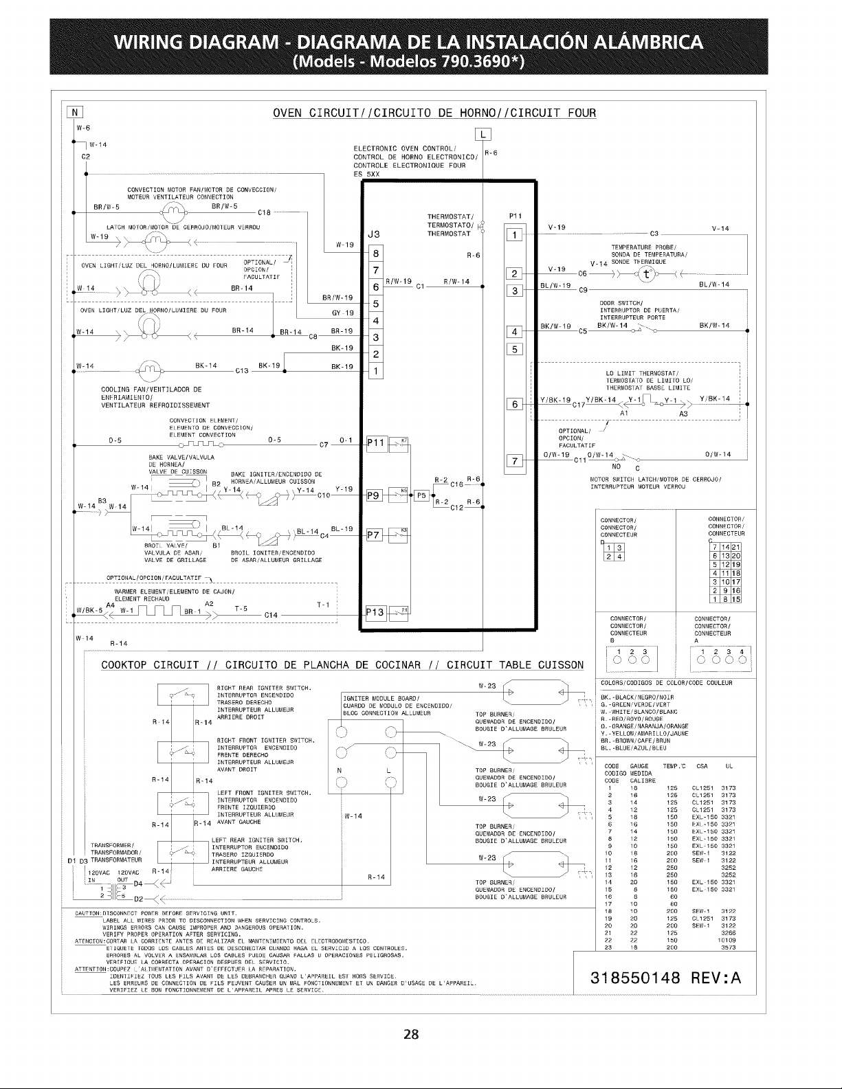
WIRING
DIAGRAM
-
DIAGRAMA
DE
LA
INSTALACION
ALAMBRICA
(Models
-
Modelos
790.3690*)
OVEN
CIRCUIT//CIRCUITO
DE
HORNO//CIRCUIT
FOUR
"
LL
|
tf
wet4
ELECTRONIC
OVEN
CONTROL/
R-6
C2
CONTROL
DE
HORNO
ELECTRONICO/
CONTROLE
ELECTRONIQUE
FOUR
ES
5XX
CONVECTION
MOTOR
FAN/MOTOR
DE
CONVECCEON/
MOTEUR
VENTILATEUR
CONVECTION
BR/W-5
(on
BR/W-5
GI
Up
C18
1
\
THERMOSTAT
/
Pit
LATCH
NoFOR,
MOTOR
BE
cepRoso/oTeuA
veRROU
TERMOSTATO/
[a
V-19 Vet4
THERMOSTAT
1
c3
W198 TEMPERATURE
PROBE/
'
;
R-6
SONDA
DE
TEMPERATURA/
|
|
OVEN
LIGHT
/LUZ
et
ONO
NLUMERE
bu
FOUR
'
ve19
V-14
SONDE
THERM
QUE
'
PACUL
ATIF
'
Riwe
14
[2
}
ce
<
(t)
oH
_—_
|
[weta
=e)
BR-
14
-
[3]
BLIW-19
og
_
BL/W-14
'
'
BR/W-19
bop
nn
22222
nnn
nen
en ne
nnn
DOOR
SWITCH/
VEN
LIGHT/LUZ
DEL
HORNO/LUMIERE
DU
FOUR
Gy-19
INTERRUPTOR
DE
PUERTA/
fo
INTERRUPTEUR
PORTE
i
}
BK/W-19
BK/W-14
BK/W-
14.
We14
BR-14 BR-14 BR-19
oA
ca
[4]
BK-19
We14
for
BK~14 ex-19 BK-19
Tor
rn
nnn
n
ns
snns
anna
nns
sess
a
assesses
aes
er
ray
OTUs
C13
LO
LIMIT
THERMOSTAT
/
'
aed
TERMOSTATO
DE
LIMITO
LO/
'
COOLING
FAN/VENTILADOR
DE
THERMOSTAT
BASSE
LIMITE
'
ENFRLAMLENTO/
(BY/8k-19
|
Y/BK-14_Y-1
v-4
Y/BK-14
|
VENTILATEUR
REFROIDISSEWENT
+
C17
ek
ye
ie
I
Al
AS
!
CONVECTION
ELEWENT/
tf
-----------------
ELEMENTO
DE
CONVECCION/
ELEMENT
CONVECTION
OPT
TONAL
/
0-5
0-5
0-1
P1711"
OPCION/
oS
UT
Lo
c7
—
ms
FAGULTATIF
BAKE
VALVE/VALVULA
OMG
6
OMT
OUW-
14
DE
HORNEA/
NO
¢
VALVE
DE_CUISSON
BAKE
IGNITER/ENCENDIDO
DE
L__
|
5
HORNEA/ALLUWEUR
CUTSSON
R-2
R-6]
MOTOR
SWITCH
LATCH/MOTOR
DE
CERROJO/
—_
v-14 y-19
C16
—
INTERRUPTEUR
MOTEUA
VERROU
mt
oo
ON
¢
oo
3
e104
B3
Lg!
Weta"
Wed
oo
_
CONNECTOR
connenT
oR!
Wid!
5
BL-14
BL-19
a
CONNECTOR/
NNECTOR
oe
A
oS
a
HP7
|
CONNECTEUR
CONNECTEUR
BROT:
owas
Lead
VALVULA
DE
ASAR/
BROIL
IGNITER/ENCENDIDO
VALVE
DE
GRILLAGE
DE
ASAR/ALLUMEUR
GRILLAGE
OPTIONAL
/OPCION/FACULTATIF
~,
WARMER
ELEMENT/ELEMENTO
DE
CAJON/
ELEMENT RECHAUD
wisk-5
4
yey
ie
rs
m
P13}
-
-
BR-1\
.
Ie
4
Mee
cia
CONNECTOR
/
GONNECTOR/
i
CONNECTOR
/
GONNECTOR/
CONNECTEUR
CONNECTEUR
W-14
We23
COLORS/CODIGOS
DE
COLOR/CODE
COULEUR
RIGHT
REAR
TGNITER
SWITCH.
.
S
4
—.
seo
MG
thascho
pongo
ee
IGNETER
MODULE
BOARD/
Le
S
BK,
-BLACK/
NEGRO /NOIR
ae
™
cE
FRADE
E
TRTERRUPTEUR
ALLUMEUR
CUARDO
DE
MODULO
DE
ENCENDIDO/
G,
-GREEN/VERDE/
VERT
BLOC
GONNECTION
ALLUMEUR
TOP
BURNER/
W.
“WHITE/BLANCO/BLANG
R14
a-14
APRIERE
OROFT
QUEMADOA
DE
ENCENDIDO/
R.
-RED/
ROYO/
ROUGE
5
Cy
BOUGIE
D‘ALLUMAGE
BRULEUR
0.
-
ORANGE
/
NARANAA/
ORANGE
©)
Coy
Y.
-
YELLOW/AMARILLO/JAUNE
RIGHT
FRONT
TGNITER
SWITCH.
W-23
BA.
-BROWN
/CAFE/BRUN
INTERRUPTOR
ENCENDIDO
co
rN
BL.
-BLUE/AZUL/BLEU
FRENTE
DERECHO
QU
LS
ct
INTERRUPTEUR
ALLUMEUR
a
:
AVANT
DROIT
N L
top
BURNER
CODE
GAUGE
=
TEMP."C
CSA
UL
A
CODIGO MEDIDA
R-14
a-14
cf ry
QUEMADOR
DE
ENCENDIDO/
CODE
CALIBRE
a
VS
BOUGIE
D'ALLUMAGE
SRULEUR
'
73
125
cL1281
3173
LEFT
FRONT
IGNITER
SWITCH.
We28
2
16
128
CL1281
3173
INTERRUPTOR
ENCENDIDO
3
14
125
CL1251
3173
FRENTE
IZQUIERDO
4
12
125
OL1251
3173
INTERRUPTEUR
ALLUMEUR
We14
5
48
150
EXL.180
3324
R14
R-14
AVANT
GAUCHE
TOP
BURNER/
6
46
180
EXL-150
3321
QUEMADOR
DE
ENCENDIDO/
7
14
150
EXL-150
3321
LEET
REAR
IGNITER
SWITCH.
BOUGIE
D'ALLUMAGE
BRULEUR
8
12
160
EXL-150
3321
TRANSFORMER
/
INTERRUPTOR
ENCENDID0
9
40,
150
EXL-180
3821
TRANSFORMADOR
/
TRASERO
TZQUIERDO
10 18
200
SEW-1
9122
Di
Dg
TRANSFORNATEUR
INTERRUPTEUR.
ALLUMEUR
W-28
4
1
16
200
SEW
3122
|
.
ARRIERE
GAUCHE
I
12
42
250
3252
|
W2ovac
yaovac
Re
R-14
S|
tg
46
250
3252
our
XL.
aba
<<
TOP
BURNER/
14
20
160
EXL-150
3321
4
See
QUEMADOR
DE
ENCENDIDO/
15
8
150
EXL-150
3321
a
SIlE
<
BOUGIE
DALLUMAGE
BRULEUR
16
8
60
be
17 40
60
CAUTION:
DESCONNECT
POWER
BEFGRE
SERVICING
UNTT.
18 30
266
SEW-1
322
LABEL
ALL
WIRES
PRIOR
TO
DISCONNECTION
WHEN
SERVICING
CONTROLS.
19 20
W250
CL
1251
3178
WIRINGS
ERRORS
CAN
CAUSE
IMPROPER
AND
DANGEROUS
OPERATION.
20
20
200
SEW-1
3122
VERIFY
PROPER
OPERATION
AFTER
SERVICING.
2
22
125
3266
ATENGTON:CORTAR
LA
GORRTENTE
ANTES
DE
REALTZAR
EL
MANTENTMYENTO
DEL
ELECTRODOMESTICO.
22 22
480
10109
oe
23
18
200
3873
ETIGUETE
TODOS
LOS
CABLES
ANTES
DE
DESCONECTAR
CUANDG
HAGA
EL
SERVICIO
A
LOS
CONTROLES.
ERRGRES
AL
VOLVER
A
ENSAMBLAR
LOS
CABLES
PUEDE
CAUSAR FALLAS
U
OPERACIONES
PELIGROSAS.
VERTFIQUE
LA
CORRECTA
GPERACION
DESPUES
DEL
SEAVICTC.
ATTENTION:
GOUPEZ
1
‘ALIMENTATION
AVANT
D'EFFECTUEA
LA
REPARATION.
IDENTIFIEZ
TQUS
LES
FILS
AVANT
DE
LES
DEBRANCHER
QUAND
L’APPAREIL
EST
HORS
SERVICE.
LES
ERREURS
DE
CONNECTION
DE
FILS
PEUVENT
CAUSER
UN
MAL
FONCTIGNNEMENT
&T
UN
DANGER
D'USAGE
DE
L'APPAREIL.
VERIFIEZ
LE
BON
FONCTIONNEMENT
DE
L'APPAREIL
APRES
LE
SERVICE.
318550148
REV:A
28