HUAWEI TECHNOLOGIES CO., LTD.
SUN2000-(100KTL, 110KTL, 125KTL) Series
Quick Guide
Issue: 11
Part Number: 31500DYQ
Date: 2021-05-07
1
1
Overview
Copyright © Huawei Technologies Co., Ltd. 2021.
All rights reserved.
•
The information in this document is subject to change without notice. Every effort has been made in
the preparation of this document to ensure accuracy of the contents, but all statements,
information, and recommendations in this document do not constitute a warranty of any kind,
express or implied.
•
Only certified electricians are allowed to operate the device. Operation personnel should understand
the composition and working principles of the grid-tied PV power system and local regulations.
•
Before installing the device, read the user manual carefully to get familiar with product information
and safety precautions. Huawei shall not be liable for any consequences caused by the violation of
the storage, transportation, installation, and operation regulations specified in this document and
the user manual.
•
Use insulated tools when installing the device. For personal safety, wear proper personal protective
equipment (PPE).
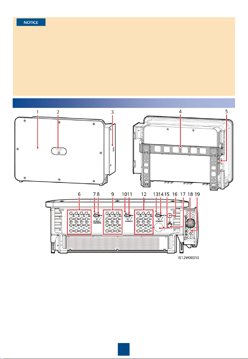
(1)
Panel
(2) LED indicators
(3) Maintenance compartment door
(4) Mounting bracket
(5) External fan tray
(6) DC input terminal group 1 (PV1
–PV8,
controlled by DC SWITCH 1)
(7) (Optional) Screw hole for
DC switch 1
(8) DC switch 1 (DC SWITCH 1)
(9) DC input terminal group 2 (PV9
–PV14,
controlled by DC SWITCH 2)
(10) (Optional
) Screw hole for DC switch 2
(11) DC switch 2 (DC SWITCH 2)
(12) DC input terminal group 3 (PV15
–PV20,
controlled by DC SWITCH 3)
(13) (Optional) Screw hole for
DC switch 3
(14) DC switch 3 (DC SWITCH 3)
(15) Ventilation valve
(16) USB port (USB)
(17) Communications port (COM)
(18) Hole for the AC output power cable
(19) Hole for the tracking system power cable
2
2
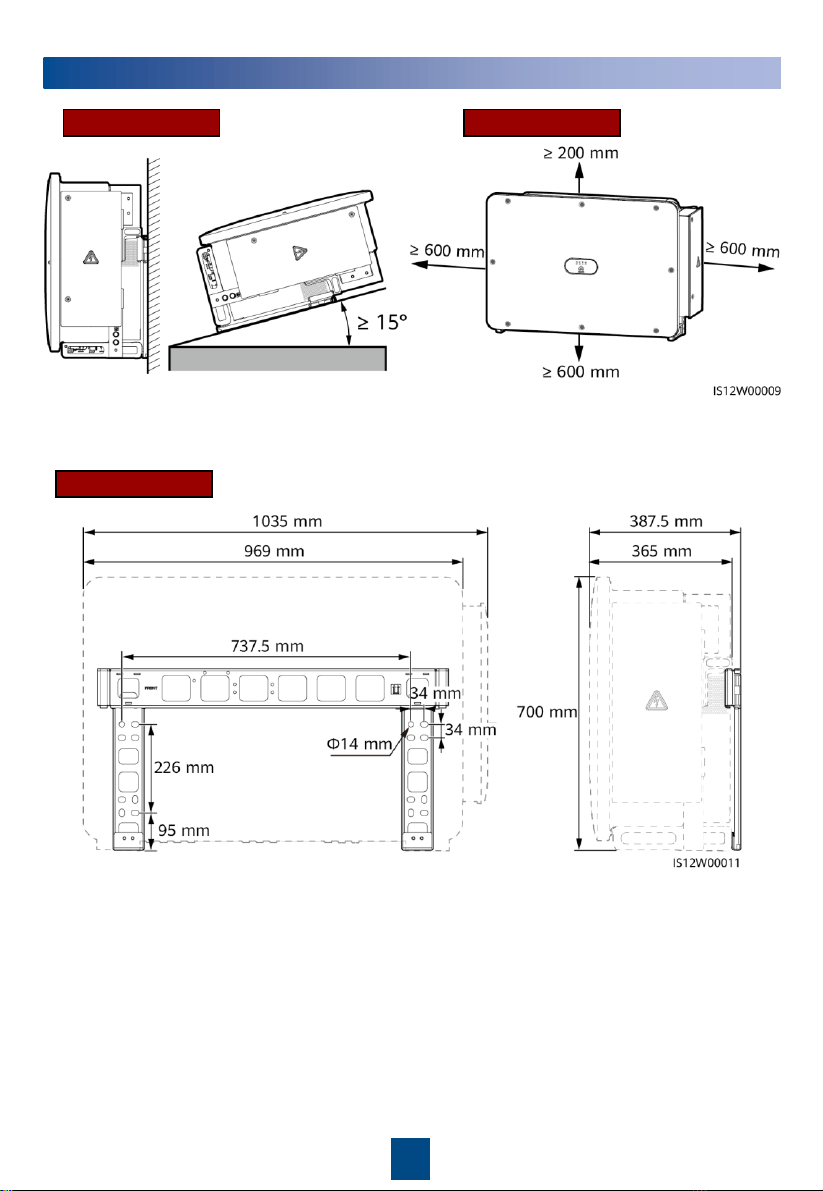
Installation Requirements
Recommended: 600 mm ≤ Bottom space ≤ 730 mm
Angle Space
Dimensions
3
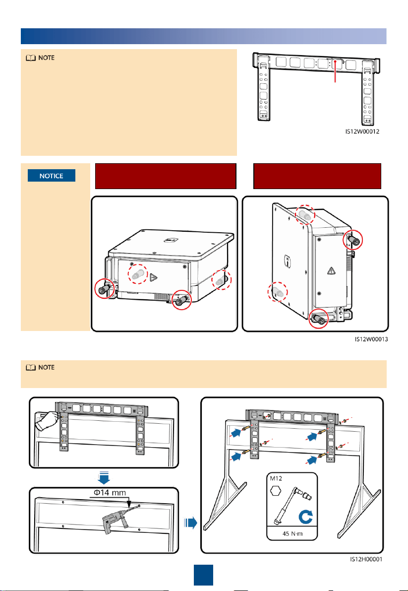
Use the handles
to facilitate
installation.
Handles are
optional and
delivered
separately.
Ensure that the
handles are
securely
installed. After
the installation
is complete,
remove the
handles and set
them aside.
Installation Positions of
Handles During Installation
Installation Positions of
Handles During Transportation
1. Install the mounting bracket.
It is recommended that anti-rust measures be taken on the positions for drilling holes.
3
Installing a Solar Inverter
•
This quick guide describes how to install a solar
inverter on a support. For details about wall-
mounted installation, see the user manual.
•
The M12x40 bolt assemblies are delivered with the
solar inverter. If the bolt assembly length does not
meet the installation requirements, prepare M12
bolt assemblies by yourself and use them together
with the delivered M12 nuts.
•
Before installing the mounting bracket, remove the
security Torx wrench and set it aside.
Position for binding the
security Torx wrench
4
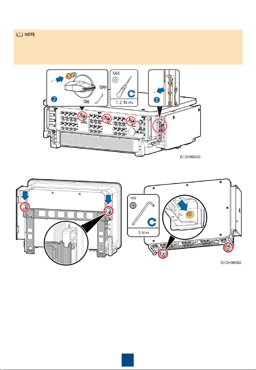
3. Install the solar inverter onto the mounting bracket. 4. Tighten security Torx screws.
2. (Optional) Install screws for locking DC switches.
• According to Australian standards, the screws for DC switches are delivered with solar
inverters. The screws are used to secure DC switches (DC SWITCH 1, DC SWITCH 2, and DC
SWITCH 3) to prevent them from being turned on by mistake.
• For the model used in Australia, perform this step to meet the local standards.
5
No.
Cable
Type
Conductor
Cross-
Sectional Area
Outer Diameter
1
PE cable
Outdoor cable and M10 OT/DT
terminals
S
p
≥ S/2
N/A
2
Tracking system
power cable
Three
-core outdoor copper cable
with dual
-layer protection
10 mm
2
15
–18 mm
3
AC output
power cable
(multi
-core)
•
If you connect a ground cable to
the ground point on the chassis
shell, you are advised to use a
three-
core (L1, L2, and L3) outdoor
cable and M12 OT/DT terminals
(L1, L2, and L3).
•
If you connect a ground cable to
the ground point in the
maintenance compartment, you do
not need to prepare a PE cable but
are advised to use a four-
core (L1,
L2, L3, and PE) outdoor cable, M12
OT/DT terminals (L1, L2, and L3),
and M10 OT/DT terminals (PE).
•
Copper cable
− S: 70–240 mm
2
− S
p
≥ S/2
•
Aluminum alloy
cable or copper-
clad aluminum
cable:
− S: 95–240 mm
2
− S
p
≥ S/2
24
–66 mm
AC output
power cable
(single
-core)
You are advised to use a single
-core
outdoor cable and M12 OT/DT
terminals.
•
Copper cable
− S: 70–240 mm
2
•
Aluminum alloy
cable or copper-
clad aluminum
cable:
− S: 95–240 mm
2
14
–32 mm
4
DC input power
cable
PV cable that meets the 1100 V
standard
4
–6 mm
2
5.5
–9 mm
5
RS485
communications
cable
Outdoor shielded twisted pair
that
meets the local standard
0.25
–1 mm
2
•
One or two
communications
cables: 4–11
mm
•
Three
communications
cables: 4–8 mm
•
The value of S
p
is valid only if the conductors of the PE cable and AC power cable use the same
material. If the materials are different, ensure that the conductor of the PE cable with a proper
cross-
sectional area produces a conductance equivalent to that of the cable specified in the table.
•
The specifications of the PE cable are subject to this table or calculated according to IEC 60364-
5-54.
Preparations
4.1
•
S and S
p
are the conductor cross-sectional areas of AC power cables and PE cables respectively.
•
The cable diameter must comply with local cable standards.
•
The factors that affect cable selection include the rated current, cable type, routing mode,
ambient temperature, and maximum expected line loss.
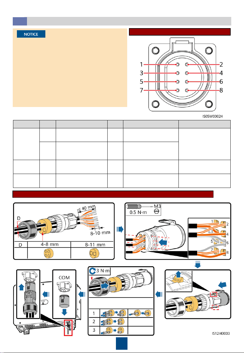
3-pin Model (125KTL) Cable Description
4
Connecting Cables
•
Connect cables in accordance with the local installation laws and regulations.
•
To prevent poor cable connection due to overstress, leave enough slack before connecting the
cables to the appropriate ports.
6
4-pin Model (100KTL/110KTL) Cable Description
No.
Cable
Type
Conductor
Cross
-
Sectional Area
Outer Diameter
1
PE cable
Outdoor cable and M10 OT/DT
terminal
s
S
p
≥ S/2
N/A
2
Tracking system
power cable
Three
-
core outdoor copper cable with
dual
-layer protection
10 mm
2
15
–18 mm
3
AC output
power cable
(multi
-core)
•
If you connect a ground cable to the
ground point on the chassis shell
and the neutral wire is not used, you
are advised to use a three-
core (L1,
L2, and L3) outdoor cable and M12
OT/DT terminals (L1, L2, and L3).
•
If you connect a ground cable to the
ground point in the maintenance
compartment and the neutral wire
is not used, you are advised to use a
four-core (L1, L2, L3, and PE)
outdoor cable, M12 OT/DT
terminals (L1, L2, and L3), and M10
OT/DT terminals (PE).
•
If you connect a ground cable to the
ground point on the chassis shell
and the neutral wire is used, you are
advised to use a four-core (L1, L2,
L3, and N) outdoor cable and M12
OT/DT terminals (L1, L2, L3, and N).
•
If you connect a ground cable to the
ground point in the maintenance
compartment and the neutral wire
is used, you are advised to use a
five-core (L1, L2, L3, N, and PE)
outdoor cable, M12 OT/DT
terminals (L1, L2, L3, and N), and
M10 OT/DT terminals (PE).
•
Copper cable
− S: 70–240
mm
2
− S
p
≥ S/2
•
Aluminum alloy
cable or copper
-
clad aluminum
cable:
− S: 95–240
mm
2
− S
p
≥ S/2
24
–66 mm
AC output
power cable
(single
-core)
You are advised to use a single
-core
outdoor cable and M12 OT/DT
terminals.
•
Copper cable
− S: 70–240
mm
2
•
Aluminum alloy
cable or copper
-
clad aluminum
cable:
− S: 95–240
mm
2
14
–32 mm
4
DC input power
cable
PV cable that meets the 1100 V
standard
4
–6 mm
2
5.5
–9 mm
5
RS485
communications
cable
Outdoor shielded twisted pair
that
meets the local standard
0.25
–1 mm
2
•
One or two
communications
cables: 4–
11 mm
•
Three
communications
cables: 4–8 mm
•
The value of S
p
is valid only if the conductors of the PE cable and AC power cable use the same
material. If the materials are different, ensure that the conductor of the PE cable with a proper
cross-sectional area produces a conductance equivalent to that of the cable specified in the
table.
•
The specifications of the PE cable are subject to this table or calculated according to IEC 60364-
5-54.
7
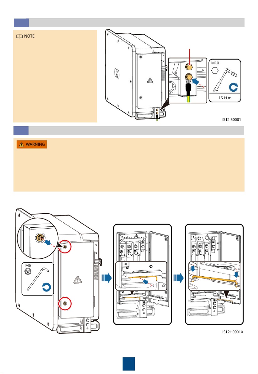
Installing a PE Cable
4.2
•
It is recommended that the
PE cable of the solar inverter
be connected to a nearby
ground point. Connect the PE
points of all solar inverters in
the same array to ensure
equipotential connections to
PE cables.
•
To enhance the corrosion
resistance of a ground
terminal, you are advised to
apply silica gel or paint on it
after connecting the PE cable.
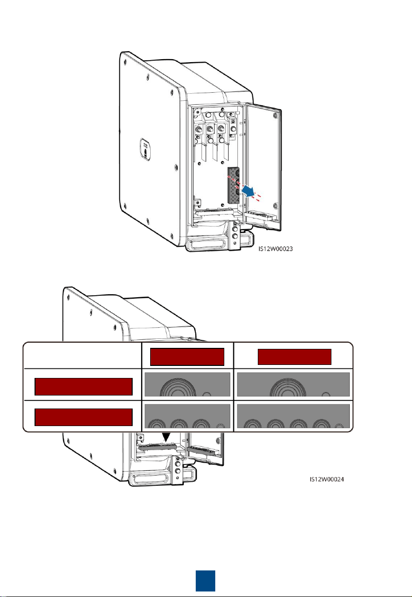
Opening the Maintenance Compartment Door
4.3
•
Do not open the panel of the solar inverter.
•
Before opening the maintenance compartment door, turn off the downstream AC output
switch and three DC switches at the bottom.
•
Do not open the maintenance compartment door in rainy or snowy days. If you have to, take
protective measures to prevent rain or snow from entering the maintenance compartment.
•
Do not leave unused screws in the maintenance compartment.
1. Loosen the screws on the
maintenance compartment door.
2. Open the maintenance compartment door and
adjust the support bar.
Reserved PE point
8
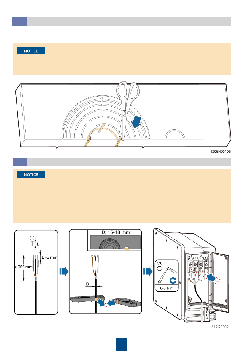
4. Select a crimping module according to the type of the AC output power cable.
3. Remove the accessories and set them aside.
3-pin Model
4-pin Model
Multi-core Cable
Single-core Cable
9
(Optional) Installing the Tracking System Power Cable
4.5
•
The tracking system should be equipped with an overcurrent protective device or component.
The length of the cable between the power cable terminal and the overcurrent protection
device or component must be less than or equal to 2.5 m.
•
The power supply of the tracking system should be an AC three-phase power grid.
•
Keep inflammable materials away from the power cable.
•
The power cable must be protected with a conduit to prevent short circuits caused by
insulation layer damage.
Removing the Rubber Rings from the Crimping Module
4.4
Use scissors to cut off the joints of the rubber rings to remove them. All rubber rings are
removed in the same way.
Remove the corresponding rubber rings strictly according to the cable diameter range, and
ensure that the crimping module is not damaged. Otherwise, the protection level of the solar
inverter will be affected.
10
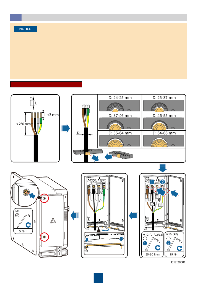
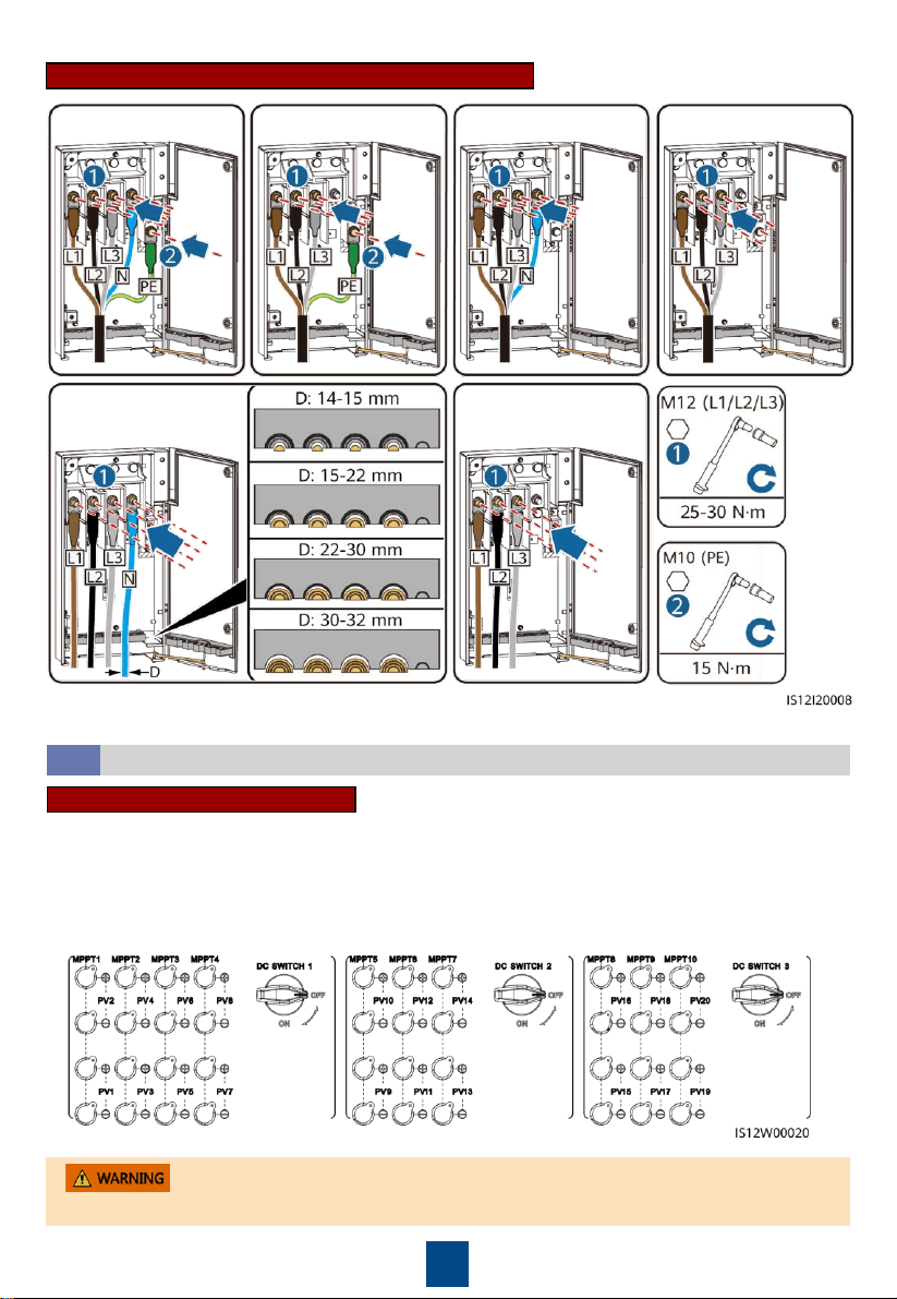
Multi-core Connection Method
Installing the AC Output Power Cable
4.6
•
This section describes how to install an AC output power cable for the 3-pin model.
•
The cable outer diameter can be measured using the ruler sticker in the maintenance
compartment.
•
Ensure that the AC output power cable is secured. Failure to do so may cause the solar inverter
to malfunction or damage to its terminal block by issues such as overheating.
•
Sufficient slack should be provided in the PE cable to ensure that the last cable bearing the
force is the PE cable when the AC output power cable bears pulling force due to force majeure.
•
If a screw on the maintenance compartment door is lost, obtain the spare screw from the
fitting bag tied at the bottom of the maintenance compartment.
11
Single-core Connection Method
Four-core cable Three-core cable Single-core cable
3-pin Model (125KTL) Cable Connections
12
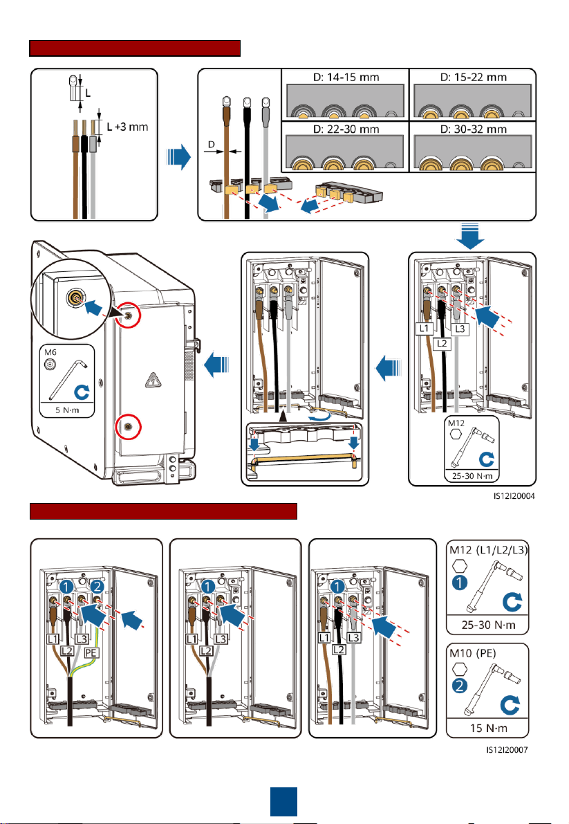
4-pin Model (100KTL/110KTL) Cable Connections
Three-core cable
Four-core cable
(including PE)
Four-core cable
(including N)
Five-core cable
Single-core cable
(including N)
Single-core cable
(excluding N)
Ensure that the PV module output is well insulated to ground.
Installing DC Input Power Cables
4.7
When the DC inputs are not fully configured, the DC input terminals must meet the following
requirements:
1. Evenly distribute the DC input power cables on the DC input terminals controlled by the three
DC switches. DC SWITCH 1 is preferred.
2. Maximize the number of connected MPPT circuits.
Selecting DC Input Terminals
13
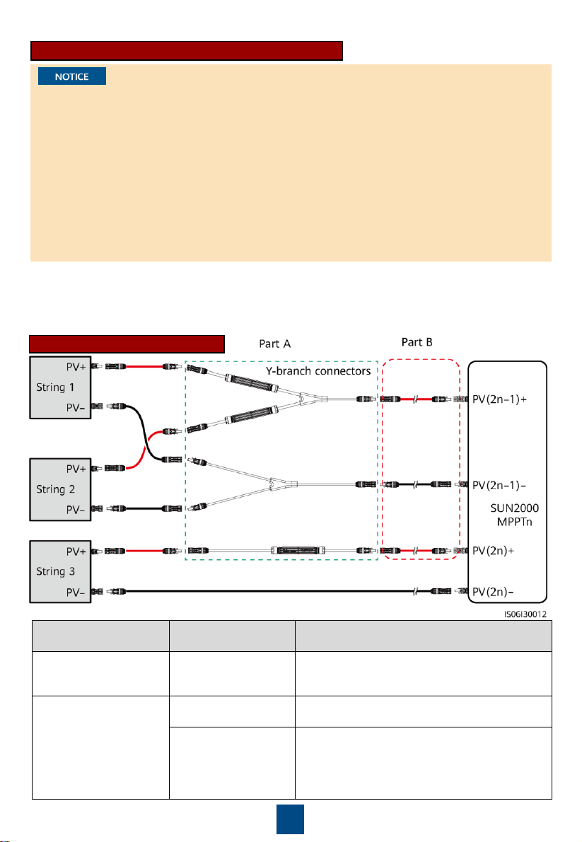
Wiring Description of Y-branch Connectors
• Y-branch connectors can be purchased from Huawei or the manufacturers based on the
following recommended models: If the rated current of the fuse of the Y-branch connector is
15 A, the recommended model is 904095944 (Luxshare) or A040959443039 (Comlink); if the
rated current of the fuse of the Y-branch connector is 20 A, the recommended model is
904095945 (Luxshare) or A040959453039 (Comlink).
• When connecting cables to recommended Y-branch connectors, ensure that the connectors to
be paired match each other and are from the same manufacturer. Otherwise, the contact
resistance of the connectors may exceed the allowed value. In this case, the connectors may be
heated and oxidized, which may cause faults.
• Ensure that the locking nuts of all connectors are tightened.
• Do not bind more than three fuse enclosures together. Otherwise, the fuses and their
enclosures may be damaged due to overheating. It is recommended that a clearance of 10 mm
or more be reserved between fuse enclosures. You are advised not to bind the fuse enclosures
with other heat emitting conductors.
Wiring rules:
1. The PV+ on the string side must be connected to the PV+ on the SUN2000 side, and the PV– on
the string side must be connected to the PV– on the SUN2000 side.
2. Preferentially and evenly connect the Y-branch connectors to the MPPTs controlled by DC
SWITCH 2 or DC SWITCH 3.
Y-branch Connector Solution
Scenario
Model of Y
-branch
Connector (Part A)
Connection Description
Connecting Y
-branch
connectors to the PV
strings (recommended)
All models
Use the DC terminals delivered with the
SUN2000s
to connect part B to the SUN2000s.
Connecting Y
-branch
connectors to the
SUN2000
Models recommended
by Huawei
Part A can be directly connected to the
SUN2000
, and part B is not needed.
Other models
To ensure that the terminals of part A
match
the DC terminals of the
SUN2000, part B is
needed to connect part A to the
SUN2000
. Use
the DC terminals delivered with the
SUN2000
to connect part B to the
SUN2000.
14
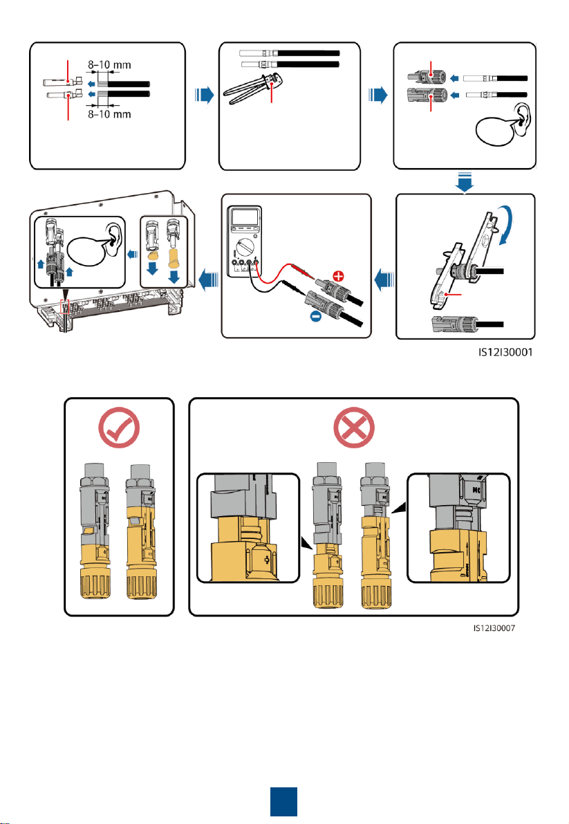
Recommended tying solution:
1. Use the positive and negative Staubli MC4 metal contacts and DC connectors supplied with
the solar inverter. Using incompatible positive and negative metal contacts and DC
connectors may result in serious consequences. The caused device damage is not covered
under any warranty.
2. Before connecting the DC input power cables, label the cable polarities to ensure correct
cable connections. Otherwise, the solar inverter may be damaged.
3. Measure the voltage at the DC input end using a multimeter set to the DC position. If the
voltage is a negative value, the DC input polarity is incorrect. Correct the polarity. If the
voltage is greater than 1100 V, too many PV modules are configured to the same string.
Remove some PV modules.
4. If the DC input power cable is reversely connected and the DC switches are set to ON, do not
perform any operation on the switches or the positive and negative connectors. Otherwise,
the device may be damaged. The caused device damage is not covered under any warranty.
Wait until the solar irradiance weakens at night and the PV string current decreases below 0.5
A. Set the three DC switches to OFF, and correct the connection of positive and negative
connectors.
5. Connect the PV string connector to the inverter connector, and then pull back the PV string
connector along the axial direction to check whether the connectors are securely connected.
6. The connector must be securely connected. Damages caused by improper connection are not
covered under the warranty.
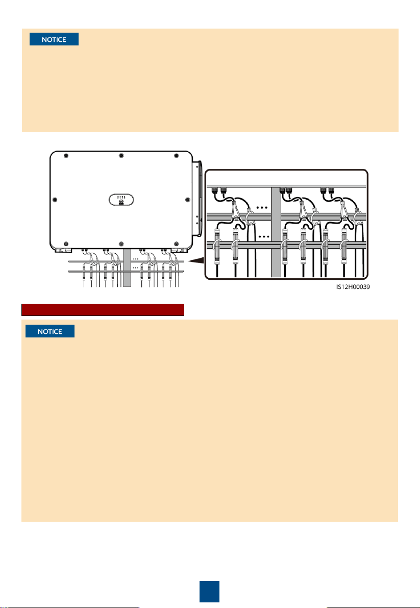
Installing a DC input power cable
• It is recommended that the Y-branch connectors be connected from the PV string side and
tied to the PV trackers.
• The DC input terminals of the solar inverter are prone to damage under stress. When Y-
branch connectors are connected to the solar inverter, bind and secure the connectors to
prevent the DC input terminals from bearing stress.
• Do not place the Y-branch connector harness on the ground. A safe distance must be
reserved between the Y-branch connector harness and the ground to avoid impact caused by
water on the ground to the harness.
15
Positive metal contact
Negative metal contact
Ensure that the cable
cannot be pulled out
after being crimped.
Positive connector
Negative
connector
Click
Click
Use a multimeter
set to the DC
position to
measure the DC
voltage.
Ensure that the
locking nut is
secured.
Open-end
spanner PV-MS
PV-CZM-22100
Connector connection:
16
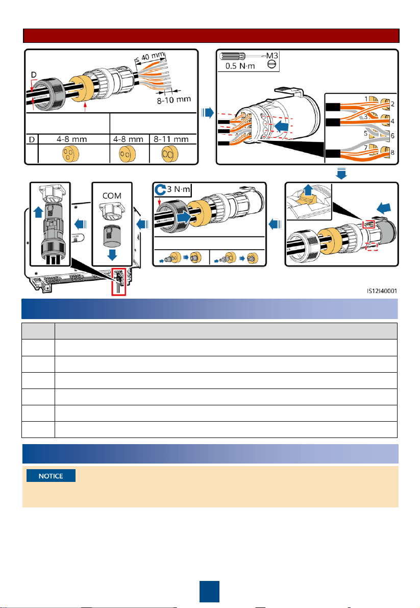
Connecting RS485 communications cables (4–8 mm four-hole rubber plug)
Number of
communications cables
Port
Pin
Definition
Pin
Definition
Description
RS485
-1
1
RS485A IN, RS485
differential signal+
2
RS485A OUT, RS485
differential signal+
Used for cascading
solar inverters or
connecting to devices
such as the
SmartLogger
.
3
RS485B IN, RS485
differential signal
–
4
RS485B OUT, RS485
differential signal
–
Protection
ground
5
PE, shielding ground
6
PE, shielding ground
N/A
RS485
-2
7
RS485A, RS485
differential signal+
8
RS485B, RS485
differential signal
–
Used for connecting to
RS485 slave devices.
Installing the RS485 Communications Cable
4.8
•
The solar inverter supports RS485
communication and MBUS communication. If
the MBUS communication mode is used, you
do not need to connect the communications
cable to the RS485-1 port.
•
This section describes how to connect three
communications cables.
•
When routing communications cables,
separate communications cables from power
cables to prevent communication from being
affected.
Pin Definitions of Communications Ports
17
5
Verifying the Installation
No.
Acceptance Criteria
1
The solar inverter is installed correctly and securely.
2
The DC switches and downstream AC switch are set to OFF.
3
All cables are connected correctly and securely.
4
Unused terminals and ports are locked by watertight caps.
5
The installation space is proper, and the installation environment is clean and tidy.
6
The maintenance compartment door is closed
and secured.
6
Powering On the System
Before turning on the AC switch between the solar inverter and the power grid, check that the
AC voltage is within the specified range using a multimeter set to the AC position.
One or two
communications cables
Three communications
cables
One communications cable
Connecting RS485 communications cables (4–8 mm two-hole or three-hole rubber plug)
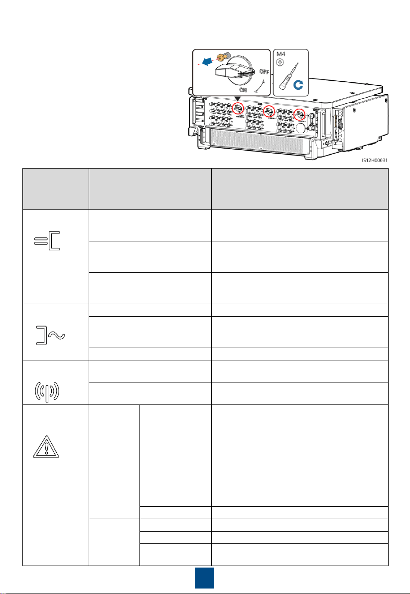
18
Indicator
Status (Blinking Fast: On for
0.2s
and then Off for 0.2s;
Blinking Slowly: On for 1s and
then Off for 1s)
Description
PV
connection
indicator
Steady green
At least one PV string is properly connected,
and the DC input voltage of the corresponding
MPPT circuit is at least 200 V.
Blinking green fast
If the alarm/maintenance indicator is red, an
environmental fault at the DC side of the solar
inverter is generated.
Off
The solar inverter disconnects from all PV
strings, or the DC input voltage of all MPPT
circuits is less than 200 V.
Grid connection
indicator
Steady green
The solar inverter is in grid
-tied mode.
Blinking green fast
If the alarm/maintenance indicator is red, an
environmental
fault at
the AC side of the solar
inverter is generated.
Off
The solar inverter is not in
grid-tied.
Communications
indicator
Blinking green fast
The solar inverter receives communication data
normally.
Off
The solar inverter has not received
communication data for 10 seconds.
Alarm/
Maintenance
indicator
Alarm status
Steady red
A major alarm is
generated.
•
If the PV connection indicator or grid
connection indicator is blinking green fast,
troubleshoot DC or AC environmental faults
as instructed by the SUN2000 app.
•
If the PV connection indicator and grid
connection indicator are both not blinking
green fast, replace components or the solar
inverter as instructed by the SUN2000 app.
Blinking red fast
A minor alarm is generated.
Blinking red slowly
A warning alarm is generated.
Local
maintenance
status
Steady green
Local maintenance succeeds.
Blinking green fast
Local maintenance fails.
Blinking green
slowly
In local maintenance or shuts down over a
command.
1. Turn on the AC switch between the solar
inverter and the power grid.
2. (Optional) Remove the screws that secure
DC SWITCH 1, DC SWITCH 2, and DC
SWITCH 3, and keep the screws properly
for the power-off maintenance later.
3. Set DC SWITCH 1 (MAIN SWITCH) at the
bottom of the solar inverter chassis to ON.
4. Check the status of the PV connection
indicator. If it is steady green, set DC
SWITCH 2 and DC SWITCH 3 to ON.
5. Observe the LED indicators to check the
operating status of the solar inverter.
19
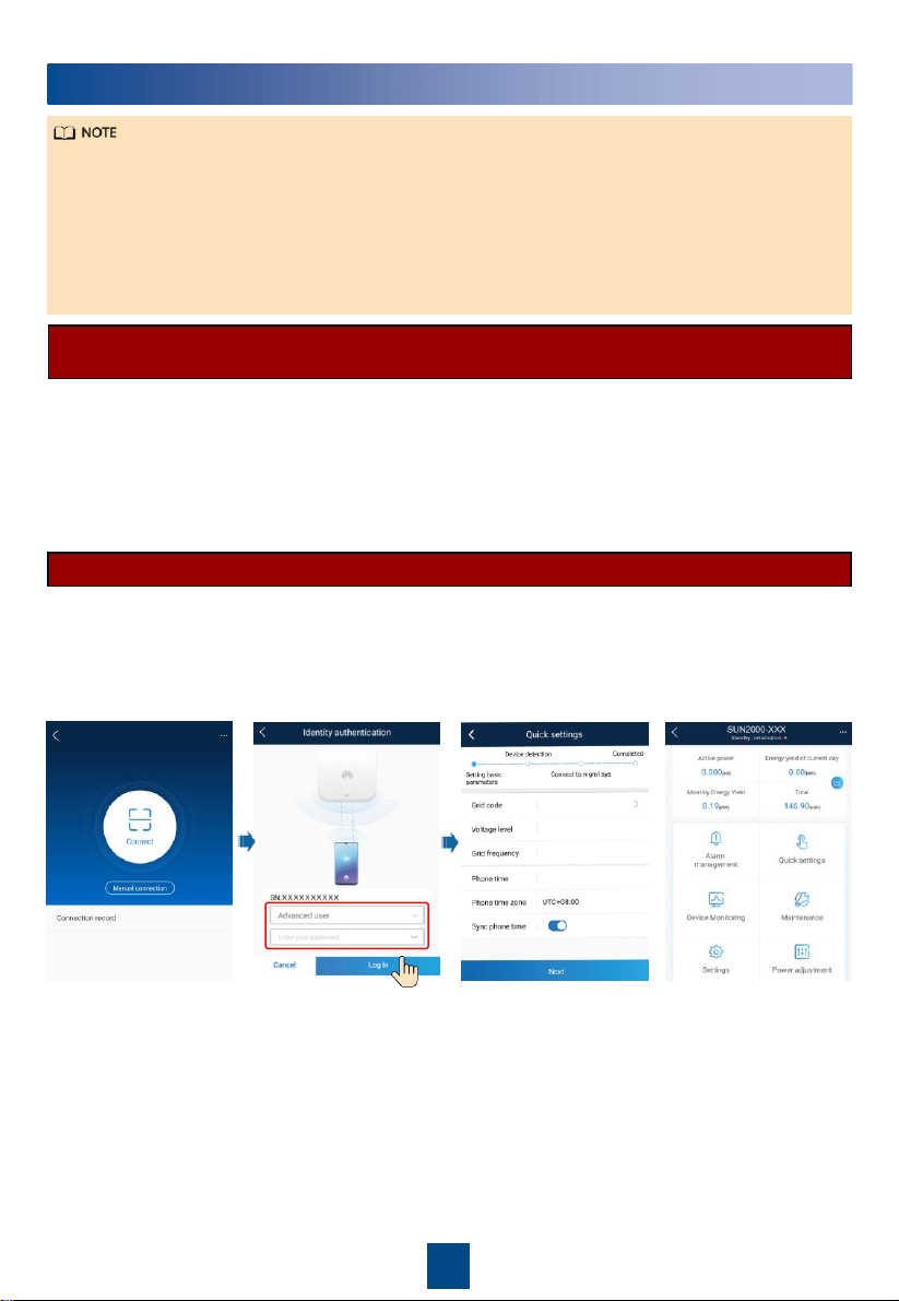
Commissioning
7
•
The FusionSolar app is recommended when the solar inverter is connected to the FusionSolar
smart PV management system. The SUN2000 app is recommended when the solar inverter is
connected to other management systems.
•
The FusionSolar app or SUN2000 app communicates with the solar inverter through the
WLAN module, Bluetooth module, or USB data cable to provide functions such as alarm
query, parameter settings, and routine maintenance.
•
Access the Huawei app store (http://appstore.huawei.com), search for FusionSolar or
SUN2000, and download the app installation package.
Scenario in Which Solar Inverters Are Connected to the FusionSolar Smart PV
Management System
1. Enable the public network of the mobile phone, open the FusionSolar app, log in to
intl.fusionsolar.huawei.com as installer account, and choose My > Device commissioning.
Then, scan the QR code on the WLAN module or the bar code on the Bluetooth, or connect a
USB data cable, a Bluetooth module, or a WLAN module to the USB port of the inverter to
implement communication between the inverter and the app.
2. Select Advanced user and enter the login password.
3. Tap Log in and go to the Quick Settings screen or function menu screen.
Scenario in Which Solar Inverters Are Connected to Other Management Systems
1. Open the SUN2000 app, scan the QR code on the WLAN module or the bar code on the
Bluetooth module, or connect a USB data cable, a Bluetooth module, or a WLAN module to
the USB port of the inverter to implement communication between the inverter and the app.
2. Select Advanced user and enter the login password.
3. Tap Log in and go to the Quick Settings screen or function menu screen.
20
•
The screenshots in this document correspond to FusionSolar app version 5.7.008 (this app is
available only on Android phones currently).
•
The screenshots in this document correspond to SUN2000 app version 3.2.00.013 (this app is
available only on Android phones currently).
•
When the WLAN connection is used, the initial name of the WLAN hotspot is Adapter-
WLAN
module SN
, and the initial password is Changeme.
•
The initial password to log in to the app for Common User, Advanced User, and Special
User is 00000a.
•
Use the initial password upon first power-on and change it immediately after login. To ensure
account security, change the password periodically and keep the new password in mind. Not
changing the initial password may cause password disclosure. A password left unchanged for
a long period of time may be stolen or cracked. If a password is lost, devices cannot be
accessed. In these cases, the user is liable for any loss caused to the PV plant.
•
Set the correct grid code based on the application area and scenario of the solar inverter.
For details about the operations of the
SUN2000 app and FusionSolar app, see the
FusionSolar App Quick Guide
. You can
download the reference by scanning the QR
code on the right.
or

Huawei Technologies Co., Ltd.
Huawei Industrial Base, Bantian, Longgang
Shenzhen 518129 People's Republic of China
solar.huawei.com