Loading ...
Loading ...
Loading ...

3
SET UP
DIAL MODE
Locate the DIAL MODE switch on the rear of the telephone body. Slide the switch to TONE unless you
have Dial-Pulse (Rotary) telephone service in your area in which case, slide the switch to the PULSE position.
RINGER CONTROL
The RINGER CONTROL switch on the rear of the telephone allows you to turn the ringer ON or OFF. You
can still make or receive calls with the ringer in OFF position, however, you will not hear the incoming ring.
RECEIVER VOLUME
The RECEIVER VOLUME CONTROL switch, located on the rear of the telephone body, allows you to adjust
the volume of the receiver earphone from LOW and HI.
HANDSET CORD
To assemble, insert the end of the handset cord into the HANDSET CORD JACK located on the left side
of the telephone body.
INSTALLATION
MODULAR WALL JACK
To install the telephone directly on a modular wall jack :
1. Connect the 15 inch line cord to the LINE CORD jack on rear of telephone body.
2. Tuck the line cord into the channel on the back of the phone.
3. Peel and stick the rubber pads on the back side of the phone in the 4 corners.
4. Hold the telephone body up next to the modular jack and plug the line cord into this jack.
5. Tuck the excess line cord into the recess provided on the back of the phone.
6. Line up the mounting holes of the telephone body with the mounting studs (screw
heads) on the modular jack or wall.
7. Push the telephone body against the wall jack and gently pull down.
WALL
If you are not mounting directly onto a modular wall jack, proceed as follows :
1. Install the 7 foot line cord into the LINE CORD jack on the back of the telephone. If the desired location
is farther than 7 foot from a wall jack, you will have to obtain a longer line cord available at most hardware
stores.
2. Place the provided TEMPLATE against the wall in the position desired.
3. Mark the wall by poking either a pen or pencil through the indicated spots on the template.
4. If there is no stud at this location, it will be necessary to install the provided wall anchors. Drill a small
pilot hole at the marked locations. Tap the anchors into the holes. Then insert screws, but DO NOT
TIGHTEN. Leave the screw heads protruding about ¼ inch.
5. If there is a stud at this location, simply install the two screws into the stud. REMEMBER,leave screw
head protruding.
6. Telephone is then mounted according to procedure detailed in MOUNTING TO
MODULAR PLUG.
NOTE : If you encounter difficulty fitting the telephone body onto the screws, or the telephone wobbles when
installed, either tighten or loosen the screws to adjust.
TABLE
1. Connect 7 foot line cord to LINE CORD jack on the rear of the telephone body.
2. Plug free end of line cord into nearest modular telephone jack.
MAKING AND ANSWERING CALLS
To get a dial tone or answer an incoming call, lift the handset.
To hang up, either replace the handset or simply press down the HANDSET CRADLE.
REDIAL
The last number dialed is automatically stored in the phone. To redial the last number, lift the handset and
press the REDIAL (coin release) button.
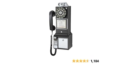
COINBOX
Coins can be deposited into the COIN SLOTS located on the top of the telephone body. The coins will ring
a bell and drop into the coin box. The coinbox may be opened by inserting the key and rotating.
ENGLISH
Loading ...
Loading ...