Loading ...
Loading ...
Loading ...
6
WORKTOPS/UNDERCOUNTERS & SANDWICH UNITS
OPERATIONS MANUAL
dry air circulation. Avoid locations near heat and moisture gen-
erating equipment including ovens, fryers, dishwashers, steam
kettles, etc. Do not install in direct sunlight (where temperatures
may exceed 100°F) or in an unheated area (where temperatures
may drop below 55°F).
Air supply to the condensing unit is critical. Restricting airflow
places excessive heat load on the unit, adversely affecting its
operation and may cause premature failure. The condenser coil
must be kept clean and free from obstruction. Condenser air fil-
ters are not recommended, since they hinder airflow, especially
if they are not replaced frequently. Contact our factory Service
Department for more information.
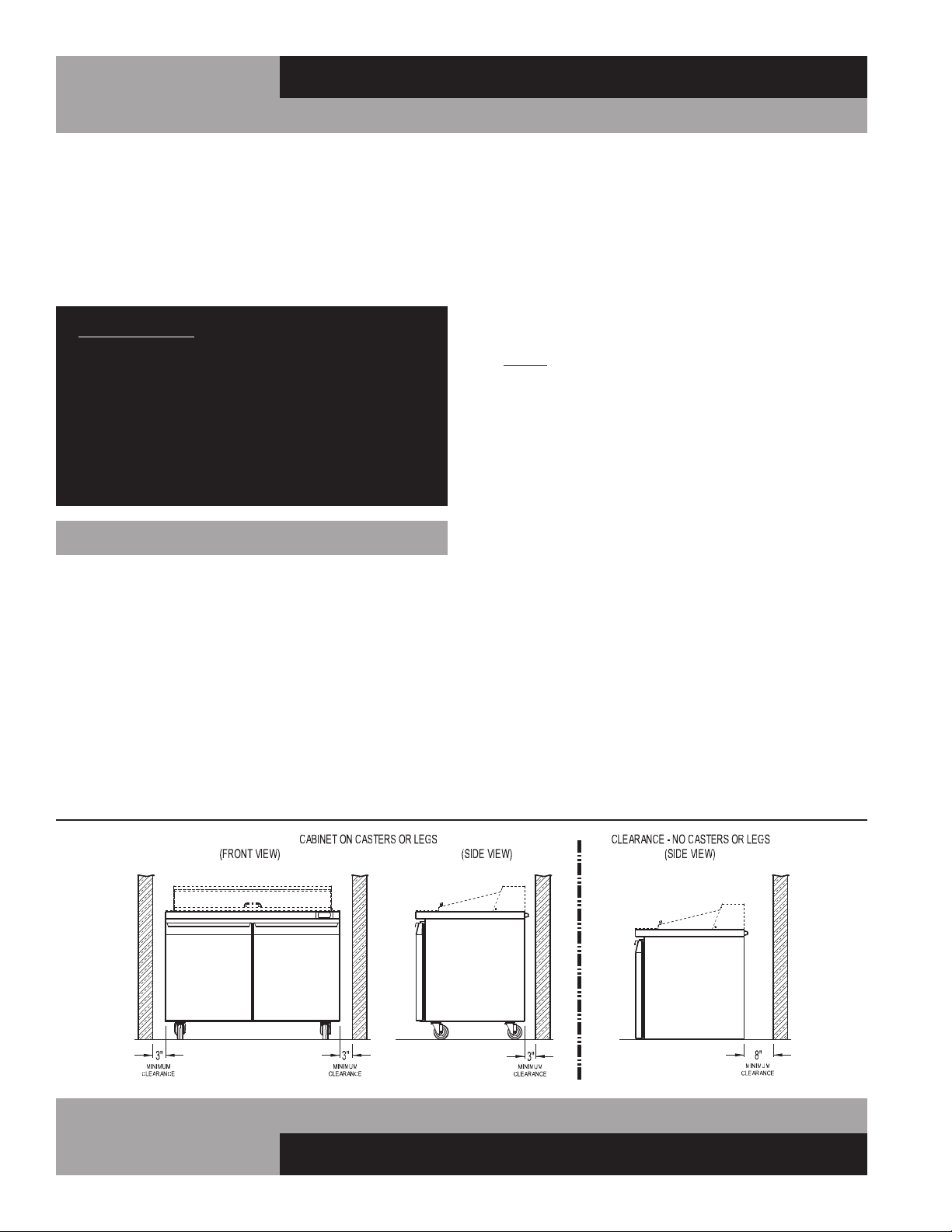
For optimum performance, all models should be installed on
casters or legs (see “Installing Casters” or “Legs”) with a
minimum 3” on each side and back of cabinet (see Figure 2).
This spacing will provide sufficient room for proper air circu-
lation and clearance to access components for cleaning and
maintenance. If any of the these conditions cannot be met, the
installer should provide special venting or air ducts, as required.
Your model has also been designed to operate sufficiently
without legs or casters and directly on the floor as long as a
minimum clearance of 8” is provided from the rear venting
louvers and the rear wall (see Figure 2). Cabinet side clearance
is not required when mounting your model directly on the floor,
without legs or casters. If any of the above conditions can not be
achieved, the installer should provide special venting or air sup-
ply ducts, or a Front-Breather Kit (see “Optional Accessories”)
can be ordered by contacting the factory.
FIGURE 2: Minimum Clearance Dimensions for Optimum Conditions
05/13/10
Four (4) bolts secure the cabinet to the wooden skid. The bolts
are located at each end on the underside of the skid. In order
to remove these bolts, tilt the cabinet backwards and place
wooden blocks at each end in order to hold it in its tilted posi-
tion. Using a ¾” socket or open end wrench, remove the bolts
and carefully slide the cabinet off of the skid. After skid removal,
the cabinet should never be moved without dollies or rollers to
avoid damage to the cabinet bottom or floor.
IMPORTANT NOTE: Do not under any circumstances, lay
your new model on its front or sides. For a brief period
of time, you may lay the cabinet on its back, but only
when its properly blocked so as not to crush the louvered
venting panel and also to allow provision for your hands,
in order to set it in its upright position without damaging
the cabinet. Do not plug in and operate model for at
least three (3) hours after cabinet is set upright from
being on its back as this can damage the compressor.
INSTALLATION AND LOCATION
Before moving the cabinet to its final point of installation, mea-
sure all doorways or passages to assure clearance. If additional
clearance is needed, you can remove the cabinet doors (see
“Removal of Doors and Door Adjustment”) and lids (when
equipped) (see “Removing Lid and Hood”).
VENTILATION
The final location site of your air cooled refrigerator or freezer
must provide a sufficient quantity of cool, clean air. All refrigera-
tion systems operate more efficiently and trouble-free with cool,
Loading ...
Loading ...
Loading ...