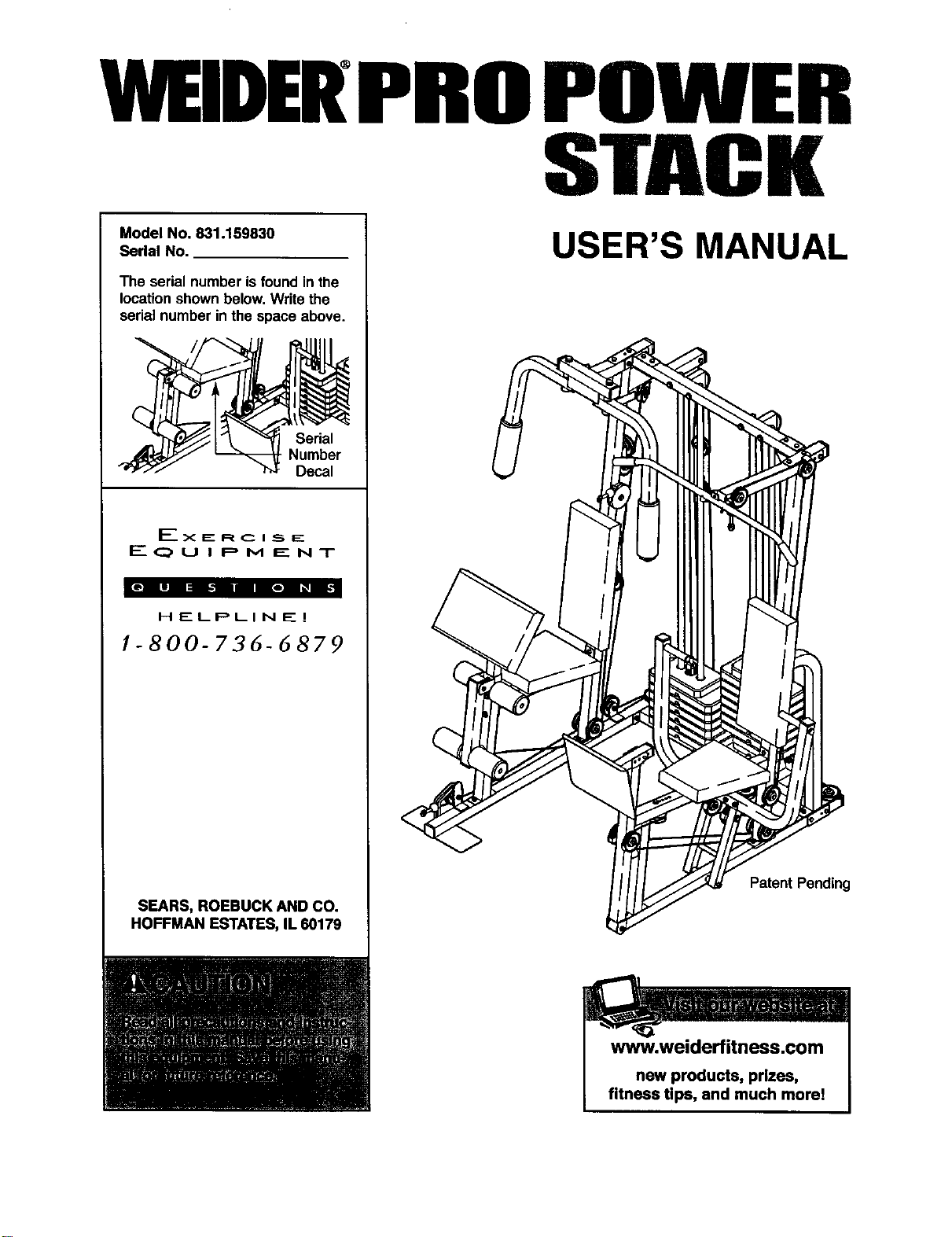
WEIDERPROPOWER
STACK
Model No. 831.159830
Serial No.
The serial number isfound in the
locationshown below,Write the
serialnumber inthe space above.
Serial
Number
Decal
Ex E: R C I _5_IE_
F---- (_ U I P M E N T
HELPLINE!
1-800-736-6879
SEARS, ROEBUCK AND CO.
HOFFMAN ESTATES, IL 60179
USER'S MANUAL
PatentPending
www.weiderfitness.com
new products, prizes,
fitness tips, and much morel
TABLE OF CONTENTS
IMPORTANT PRECAUTIONS ............................................................. 3
BEFORE YOU BEGIN ................................................................... 4
ASSEMBLY ........................................................................... 5
ADJUSTMENTS ...................................................................... 25
WEIGHT RESISTANCE CHART .......................................................... 27
TROUBLESHOOTING AND MAINTENANCE ................................................ 28
CABLE DIAGRAMS ................................................................... 30
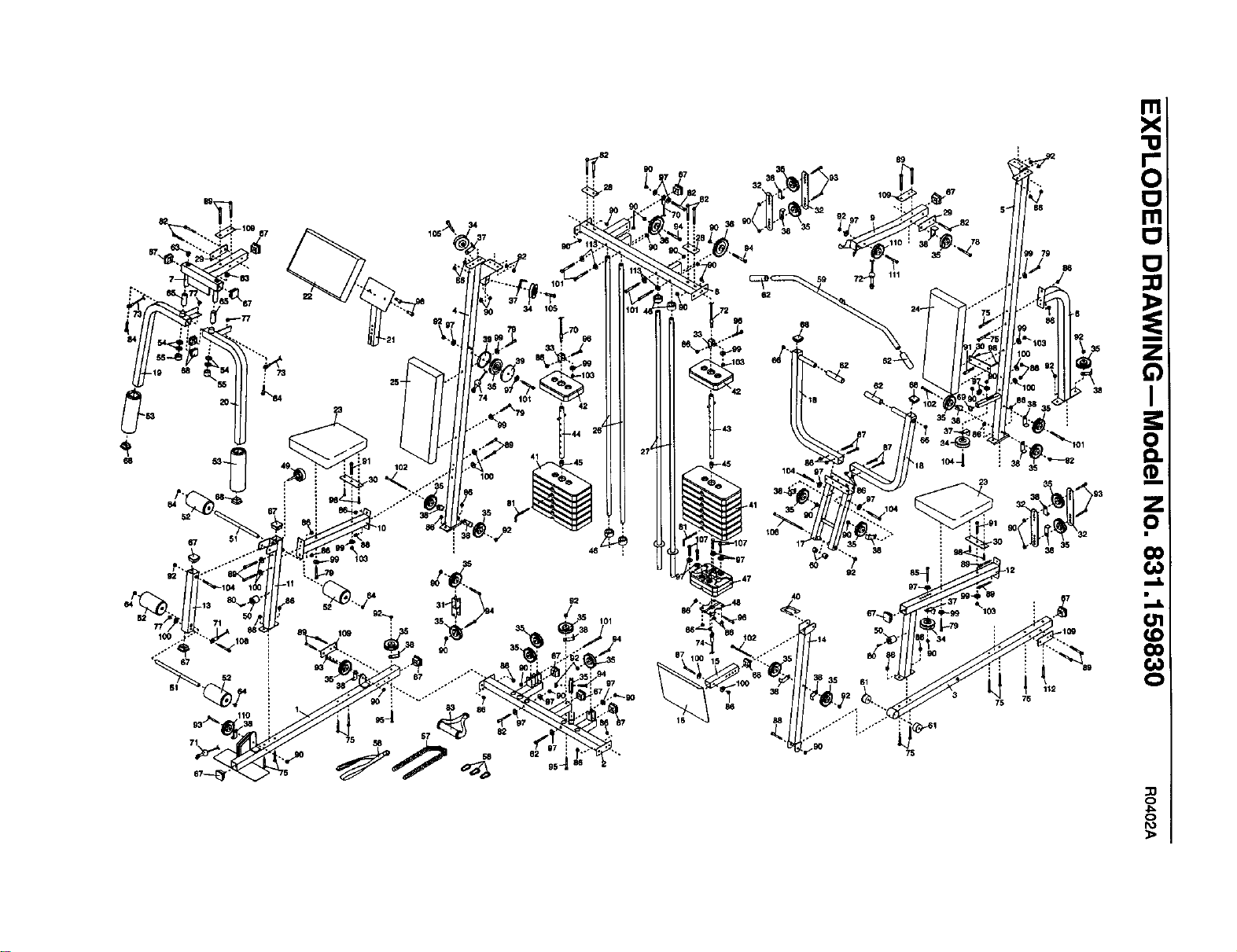
ORDERING REPLACEMENT PARTS ............................................... Back Cover
FULL 90 DAY WARRANTY ....................................................... Back Cover
Note: A PART LIST/EXPLODED DRAWING and a PART IDENTIFICATION CHART are attached in the center of
this manual. Remove the PART LIST/EXPLODED DRAWING and the PART IDENTIFICATION CHART before
beginning assembly.
2
IMPORTANT PRECAUTIONS
3
BEFORE YOU BEGIN
Thank you for selectingthe innovativeand versatile
WELDER° PRO POWER STACK weight system.The
POWER STACK offers a uniqueselectionofweight
stationsdesignedto develop every majormuscle
groupof the body.Whether yourgoal isto tone your
body,builddramatic musclesize and strength,or
improve yourcardiovascularsystem,the POWER
STACK willhelp youto achievethe resultsyouwant.
For your benefit, read this manual carefully before
using the POWER STACK weight system. Ifyou
have additionalquestions,please call ourtoll-free
HELPLINE at 1-800-736-6879, Monday through
Saturday,7 a.m. until 7 p.m. Central Time (excluding
holidays).To helpus assistyou, please note the prod-
uctmodel number and serial number beforecalling.
The model number is831.159830. The serialnumber
can be found on a decal attached to the weightsystem
(see the frontcover of this manual).
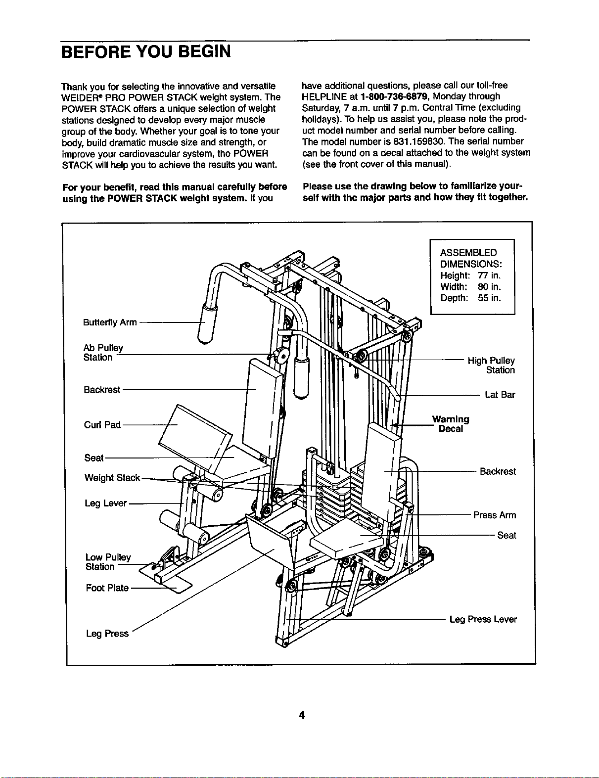
Please use the drawing below to familiarize your-
self with the major parts and how they fit together.
ButterflyArm
ASSEMBLED
DIMENSIONS:
Height: 77 in.
Width: 80 in.
Depth: 55 in.
Ab Pulley
Station
Backrest
High Pulley
Station
Lat Bar
Curl Pad
Warning
-- Decal
Seat,
Backrest
Leg Level
Low Pulley
Station
FootPlate --
Press Arm
Seat
Leg Press
Leg PressLever
4
ASSEMBLY
Assembly Requires Two Persons
Foryour convenienceand safety,assemble the
weight system withthe helpof another person.
Set Aside Enough Time
Due to the many features of the weightsystem,the
assembly processwillrequireseveral hours.By
settingaside plenty oftime and by decidingto
make the task enjoyable, assemblywill gosmoothly.
You may wantto assemble the weightsystemover
a coupleof evenings.
Select a Location for the Weight System
Because ofitsweight and size, the weightsystem
shouldbe assembled in the locationwhere itwill be
used. Make sure thatthere is enoughroomtowalk
aroundthe weightsystem as you assemble it.
How to Unpack the Box
To make assembly as easy as possible,we have
dividedthe assembly processintofour stages.The
parts needed for each stage are found in individual
bags. Important: Walt unUl you begin each stage
to open the parts bag for that stage. Place all
parts of theweight system in a cleared area and
remove the packing materials. Do not disposeof
the packingmaterialsuntilassemblyiscompleted.
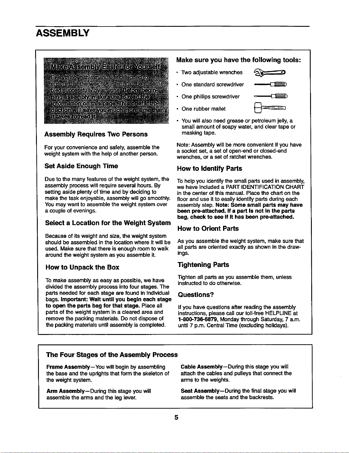
Make sure you have the following tools:
• Two adjustable wrenches
• One standard screwdriver
• One phillips screwdriver
• One rubber mallet
• Youwillalso need grease or petroleum jelly, a
small amount of soapywater, and clear tape or
masking tape.
Note: Assembly willbe more convenientifyou have
a socket set, a set of open-endor closed-end
wrenches, or a set of ratchetwrenches.
How to Identify Parts
To help you identifythe smallpartsused inassembly,
we have includeda PARTIDENTIFICATION CHART
in the center of thismanual. Placethe charton the
floor and use itto easily identifyparts duringeach
assembly step. Note: Some small parts may have
been pre-attached. If a part Is not In the parts
bag, check to see If It has been pre-attached.
How to Orient Parts
As you assemble the weightsystem, make sure that
all parts are orientedexactlyas shownin the draw-
ings.
Tightening Parts
"13ghtenall parts as you assemble them, unless
instructedtodo otherwise.
Questions?
If you have questionsafter readingthe assembly
instructions,please sail ourtoll-free HELPLINE at
1-800-736-6879, Monday through Saturday,7 a.m.
until7 p.m. Central"13me(excludingholidays).
The Four Stages of the Assembly Process
Frame Assembly--You will begin by assembling
the base and the uprightsthat form the skeletonof
the weightsystem.
Arm Assembly--During this stage you will
assemble the arms and the leg lever.
Cable Assembly--During this stageyou will
attach thecables and pulleysthatconnectthe
arms tothe weights.
Seat Assembly--Dudng the final stage you will
assemble the seats and the backrests.
5
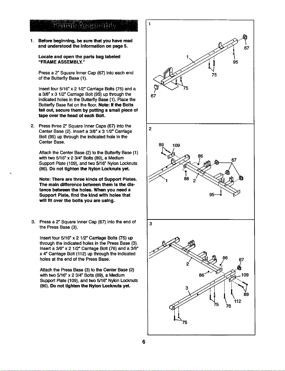
1. Before beginning, be sure that you have read
and understood the Information on page 6.
Locate and open the parts bag labeled
"FRAME ASSEMBLY."
Pressa 2"Square Inner Cap (67) intoeach end
of the ButterflyBase (1).
Insert four 5/16" x 2 1/2" Carriage Bolts (75) and a
a 3/8" x 3 1/2" Carriage Bolt (95) up through the
indicatedholes in the Butterfly Base (1). Place the
Butterfly Base flat on the floor. Note: If the Bolts
fall out, secure them by putting a small piece of
tape over the heed of each Bolt.
2. Press three 2" Square Inner Caps (67) intothe
Center Base (2). Insert a 3/8" x 3 1/2" Carriage
Bolt (95) up through the indicated hole in the
Center Base.
Attachthe Center Base (2) to the ButterflyBase (1)
withtwo 5/16"x 2 3/4" Bolts (89), a Medium
Support Plate (109), and two 5/16" Nylon Locknuts
(86). Do not tighten the Nylon Locknuts yet.
Note: There are three kinds of Support Plates.
The main difference between them Is the dis-
tance between the holes. When you need a
Support Plate, find the kind with holes that
will fit over the bolts you are using.
3,
Press a 2" Square Inner Cap (67) into the end of
the Press Base (3).
Insert four 5/16" x 2 1/2" Carriage Bolts (75) up
through the indicatedholes in the Press Base (3).
Insert a 3/8" x 2 1/2" Carriage Bolt (76) and a 3/8"
x 4" Carriage Bolt (112) up through the indicated
holes at the end of the Press Base.
Attachthe PressBase (3) tothe Center Base(2)
withtwo 5/16" x 2 3/4" Bolts (89), a Medium
SupportPlate (109), and two 5/16" NylonLocknuts
(86). Do not tighten the Nylon Locknuts yet.
67
2
67
95
75
75
89
109
86
67
3
2
75
86 67
109
112
78
4. 4
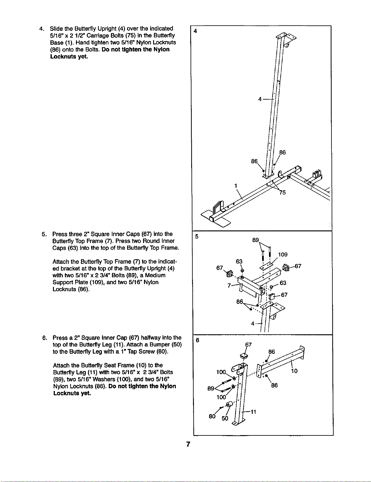
Slidethe ButterflyUpright(4) over the indicated
5/16" x 2 112"Carriage Bolts (75) in the Butterfly
Base (1). Hand tighten two 5/16" Nylon Locknuts
(86) onto the Bolts. Do not Ughten the Nylon
Locknuts yet.
5. Press three 2" Square Inner Caps (67) intothe
ButterflyTop Frame (7). Presstwo Round Inner
Caps (63) intothe top of the Butterfly Top Frame.
Attach the ButterflyTop Frame (7) tothe indicat-
ed bracket at the top of the Butterfly Updght(4)
with two 5/16" x 2 3/4" Bolts (89), a Medium
SupportPlate (109), and two 5/16" Nylon
Locknuts(86).
6.
Press a 2"Square Inner Cap (67) halfwayintothe
top ofthe ButterflyLeg (11).Attach a Bumper (50)
tothe ButterflyLeg witha 1"Tap Screw (80).
Attachthe ButterflySeat Frame (10) to the
ButterflyLeg (11) with two 5/16" x 2 3/4" Bolts
(89), two 5/16" Washers (100), and two 5/16"
Nylon Locknuts (86). Do not Ughten the Nylon
Locknuts yet.
5
86
86\
1
75
,_" -11
8O
7
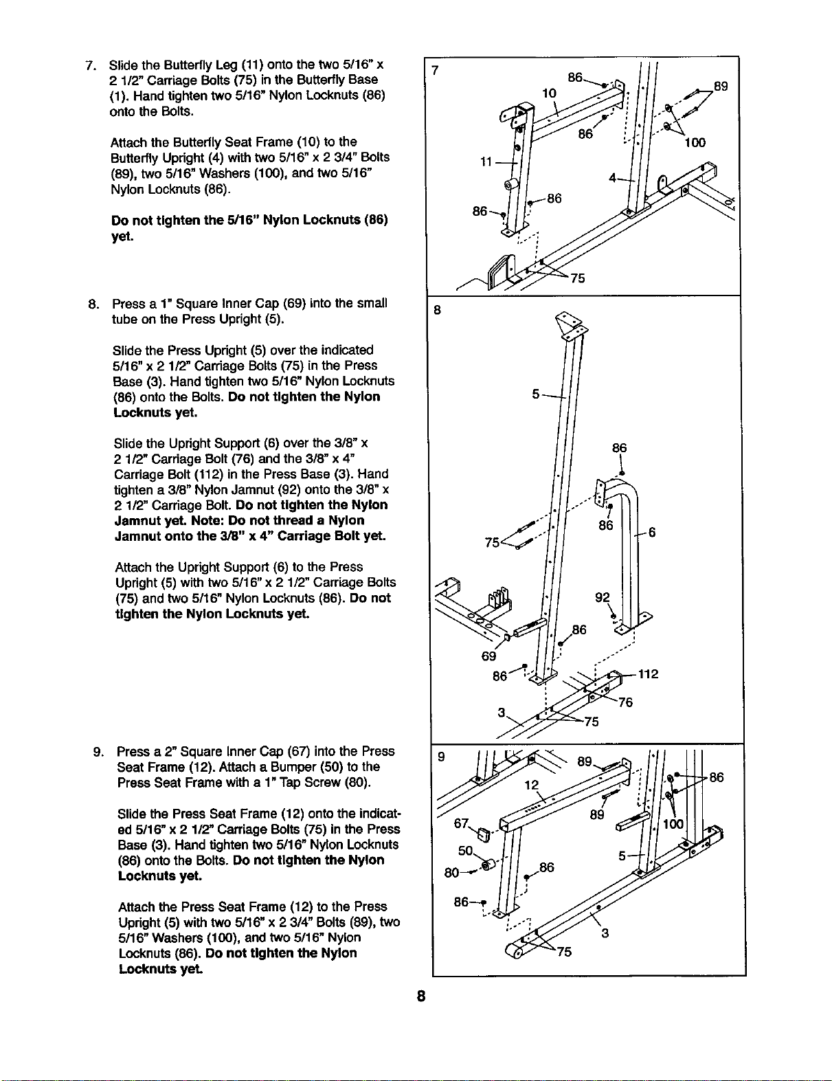
7. Slidethe ButterflyLeg (11) ontothe two 5116"x
2 1/2"Carriage Bolts (75) inthe ButterflyBase
(1). Hand tighten two 5/16" Nylon Locknuts (86)
onto the Bolts.
Attachthe Butterfly Seat Frame (10) to the
ButterflyUpright(4) with two 5/16" x 2 3/4" Bolts
(89), two 5116"Washers (100), and two 5/16"
Nylon Lccknuts (86).
Do not tighten the 5/16" Nylon Locknuts (86)
yet.
8.
Pressa 1"Square Inner Cap (69) into the small
tube on the Press Upright (5).
Slidethe Press Upright(5) over the indicated
5/16" x 2 112"Carriage Bolts (75) inthe Press
Base (3). Hand tighten two 5/16" Nylon Locknuts
(86) onto the Bolts. Do not tighten the Nylon
Locknuts yet.
Slide the Updght Support (6) over the 3/8" x
2 1/2" Cardege Bolt (76) and the 318"x 4"
Carriage Bolt (112) in the Press Base (3). Hand
tighten a 3/8" Nylon Jamnut (92) onto the 3/8" x
2 112"Carriage Bolt. Do not tighten the Nylon
Jamnut yet. Note: Do not thread a Nylon
Jamnut onto the 3/8" x 4" Carriage Bolt yet.
Attach the UprightSupport(6) to the Press
Upright(5) with two 5/16" x 2 1/2" Carriage Bolts
(75) and two 5/16" Nylon Locknuts(86). Do not
Ughten the Nylon Locknuts yet.
9. Pressa 2" Square Inner Cap (67) intothe Press
Seat Frame (12). Attach a Bumper(50) to the
Press Seat Frame with a 1"TapScrew (80).
Slide the Press Seat Frame (12) ontothe indicat-
ed 5116"x 2 1/2" Carriage Bolts(75) in the Press
Base (3). Hand tightentwo 5/16" Nylon Locknuts
(86) ontothe Bolts. Do not tighten the Nylon
Locknuts yet.
Attach the PressSeat Frame (12) to the Press
Upright(5) with two 5/16" x 2 3/4" Bolts(89), two
5/16" Washers (100), and two 5/16" Nylon
Locknuts(86). Do not tighten the Nylon
Locknuts yet.
8
8
11
10
5
89 ,/1/ III
50 . 5
_75
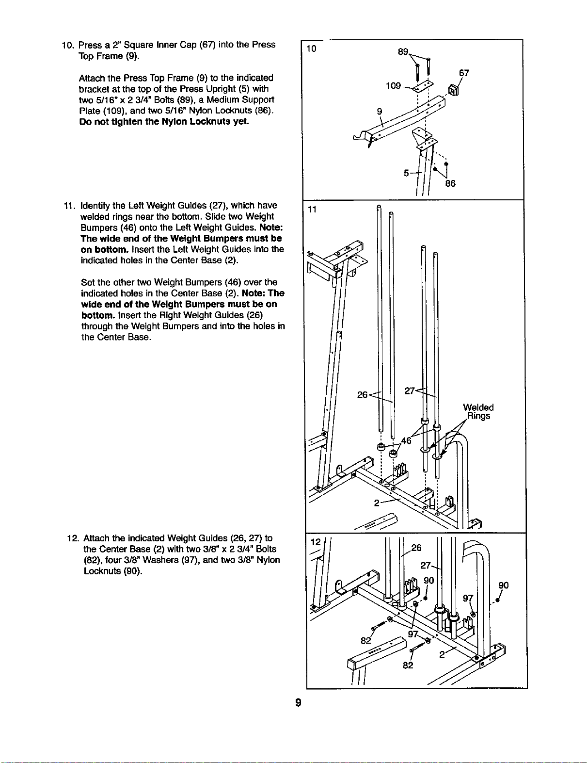
10. Press a 2"Square Inner Cap (67) intothe Press
Top Frame (9).
Attachthe Press TopFrame (9) to the indicated
bracket at the top of the Press Upright (5) with
two 5/16" x 2 314"Bolts(89), a Medium Support
Plate (109), and two 5/16" Nylon Locknuts(86).
Do not tighten the Nylon Locknuts yet.
11. Identifythe LeftWeight Guides (27), whichhave
welded ringsnear the bottom.Slide two Weight
Bumpers (46) ontothe LeftWeight Guides. Note:
The wide end of the Weight Bumpers must be
on bottom. Insertthe LeftWeight Guides intothe
indicatedholes inthe Center Base (2).
Set the other two Weight Bumpers(46) over the
indicatedholes in the Center Base (2). Note: The
wide end of the Weight Bumpers must be on
bottom. Insert the Right Weight Guides (26)
throughthe Weight Bumpers and intothe holesin
the Center Base.
12. Attachthe indicatedWeight Guides (26, 27) to
the Center Base (2) withtwo 3/8" x 2 3/4" Bolts
(82), four3/8" Washers (97), and two 3/8" Nylon
Locknuts (90).
10
11
26< 27<
Welded
_.Rings
9
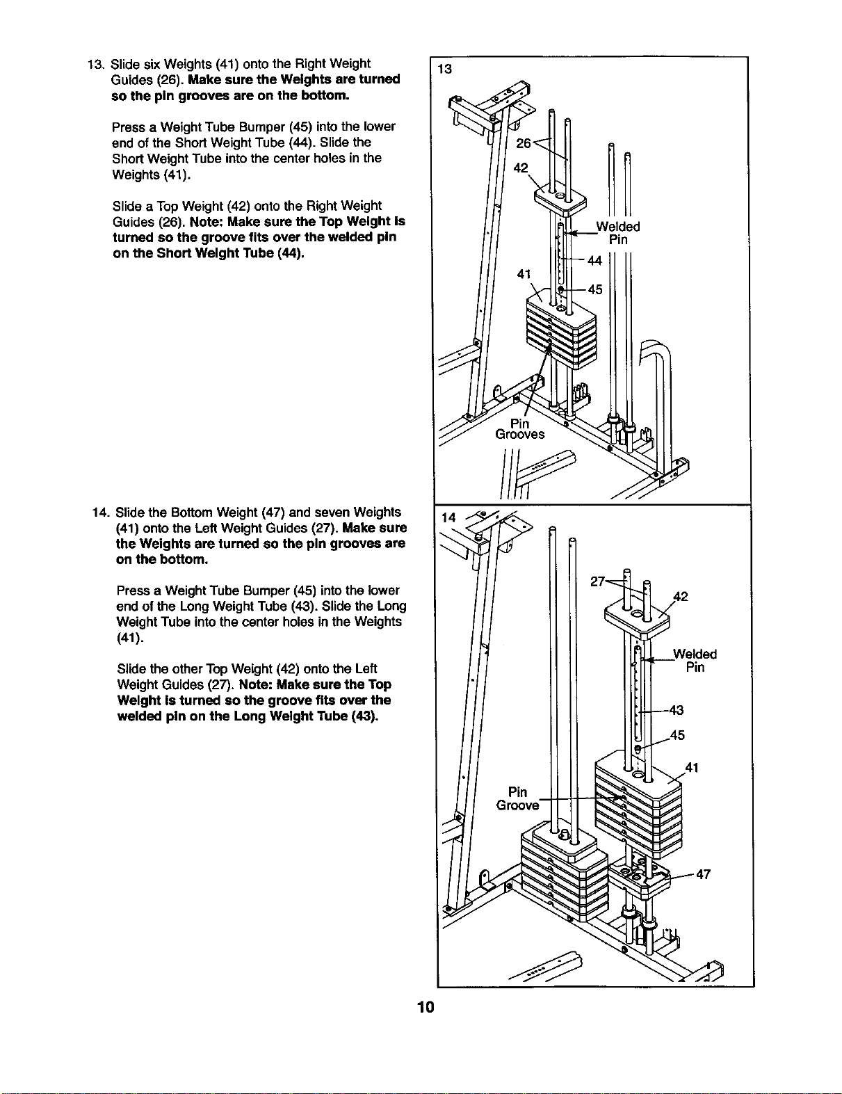
13. Slide sixWeights (41) ontothe Right Weight
Guides (26). Make sure the Weights are turned
so the pin grooves are on the bottom.
Press a Weight Tube Bumper (45) intothe lower
end ofthe ShortWeight Tube (44). Slidethe
ShortWeight Tube intothe center holes in the
Weights (41).
Slidea Top Weight (42) onto the RightWeight
Guides (26). Note: Make sure the Top Weight Is
turned so the groove fits over the welded pin
on the Short Weight Tube (44).
14. Slidethe BottomWeight (47) and seven Weights
(41) ontothe LeftWeight Guides(27). Make sure
the Weights are turned so the pin grooves are
on the bottom.
Pressa Weight Tube Bumper(45) intothe lower
end ofthe Long Weight Tube (43). Slidethe Long
Weight Tube intothe center holesin the Weights
(41).
Slidethe otherTop Weight (42) ontothe Left
Weight Guides (27). Note: Make sure the Top
Weight Is tumed so the groove fits over the
welded pin on the Long Weight Tube (43).
13
f_
Pin
41
10
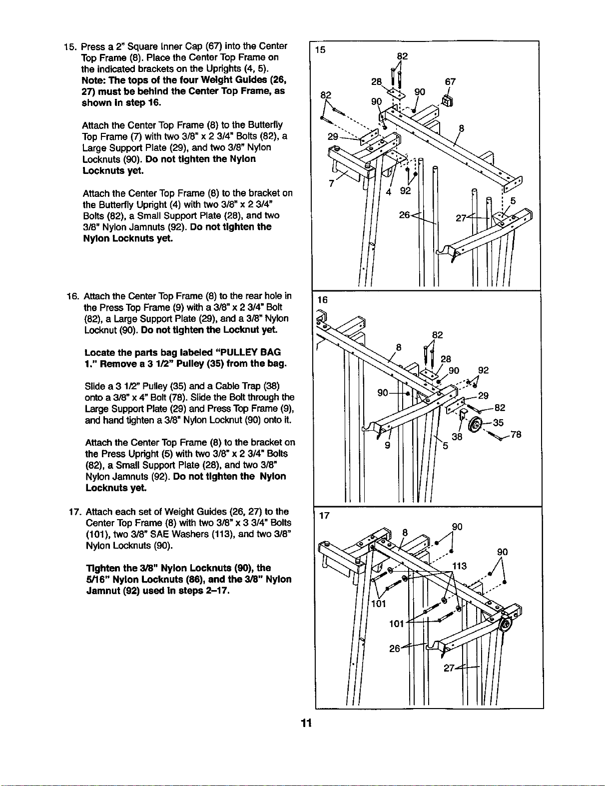
15. Press a 2"Square Inner Cap (67) intothe Center
TopFrame (8). Place the CenterTop Frame on
the indicatedbracketson the Uprights(4, 5).
Note: The tops of the four Weight Guides (26,
27) must be behind the Center Top Frame, as
shown In step 16.
Attachthe Center Top Frame (8) tothe Butterfly
Top Frame (7) with two3/8" x 2 3/4" Bolts(82), a
Large SupportPlate (29), and two 318"Nylon
Locknuts(90). Do not tighten the Nylon
Locknuts yet.
Attach the Center TopFrame (8) tothe bracket on
the ButterflyUpright(4) with two 3/8" x 23/4"
Bolts(82), a Small Support Plate (28), and two
3/8" NylonJamnuts (92). Do not tighten the
Nylon Locknuts yet.
16. Attachthe CenterTopFrame (8) to therear holein
the PressTop Frame (9) witha 3/8" x2 3/4" Bolt
(82), a LargeSupportPlate (29), and a 3/8" Nylon
Locknut(90). Do not tighten the Locknut yet.
Locate the parts bag labeled "PULLEY BAG
1." Remove a 3 1/2" Pulley (35) from the bag.
Slide a 3 1/2"Pulley(35) and a CableTrap (38)
ontoa 3i8" x 4"Bolt(78). Slidethe Boltthrough the
Large SupportPlate (29) and PressTopFrame (9),
and handtightena 3/8" NylonLocknut(90)ontoit.
Attachthe CenterTop Frame (8) tothe bracketon
the Press Upright(5) with two3/8" x 2 3/4" Bolts
(82), a Small SupportPlate (28), and two 3/8"
NylonJamnuts (92). Do not tighten the Nylon
Locknuts yet.
17. Attach each set ofWeight Guides (26, 27) to the
CenterTop Frame (8) withtwo 3/8" x 3 314"Bolts
(101), two 3/8" SAE Washers (113), and two 318"
Nylon Locknuts(90).
Tighten the 3/8" Nylon Locknuts (90), the
5/16" Nylon Locknuts (86), and the 3/8" Nylon
Jamnut (92) used In steps 2-17.
15
82
82
28
90
67
8
16
f
f
_<
82
28
t 90 92
T' -35
"5 38 _178
17
"_ 8 90
"'"° 113 u/_
11
18 92 11
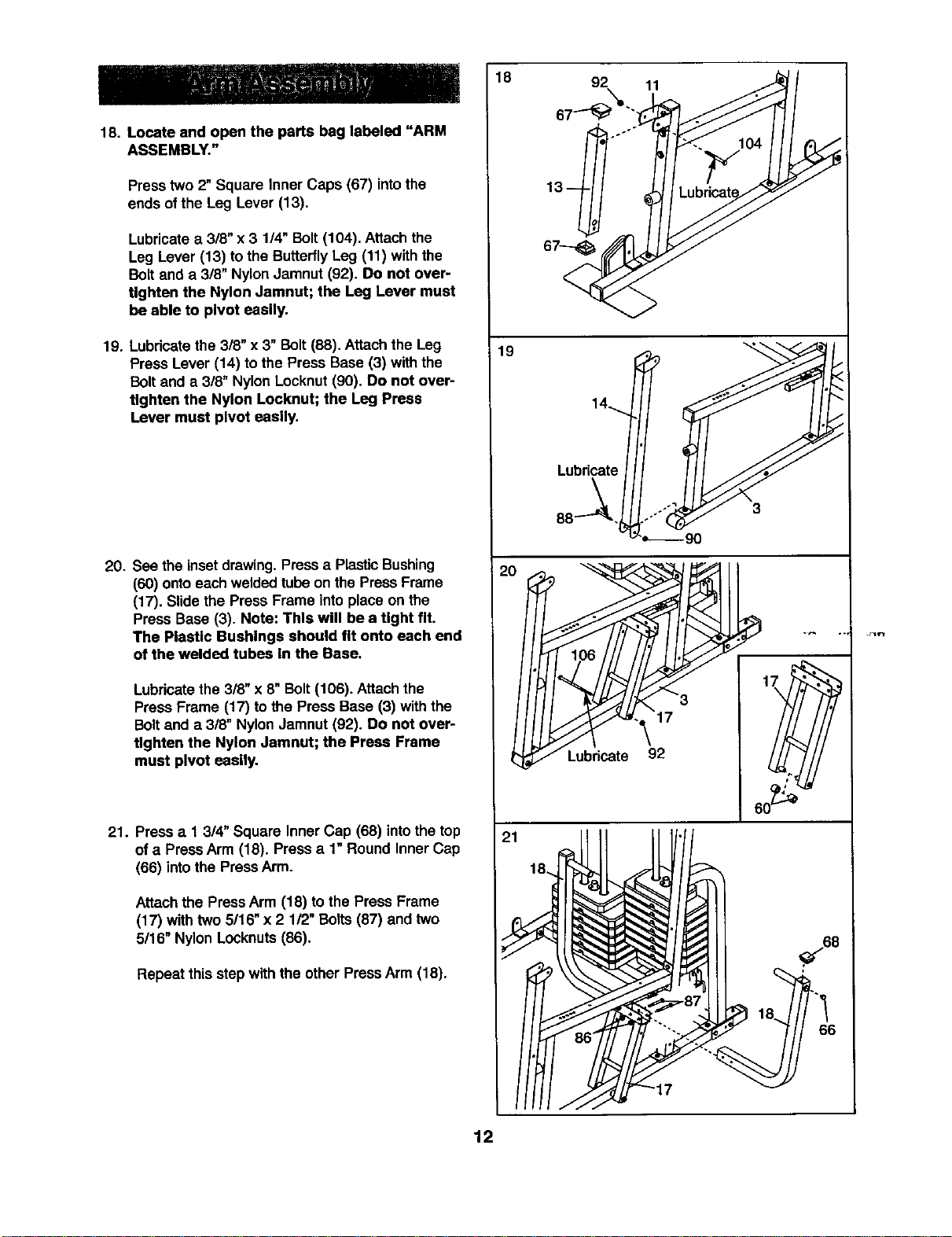
18. Locate and open the parts bag labeled "ARM
ASSEMBLY."
Press two 2" Square Inner Caps (67) intothe
ends of the Leg Lever (13).
Lubricatea 3/8" x 3 1/4" Bolt (104). Attach the
Leg Lever (13) to the ButterflyLeg (11) with the
Bolt and a 3/8" Nylon Jamnut (92). Do not over-
tighten the Nylon Jamnut; the Leg Lever must
be able to pivot easily.
19. Lubricatethe 3/8" x 3" Bolt(88). Attach the Leg
Press Lever (14) to the Press Base (3) withthe
Boltand a 3/8" NylonLocknut(90). Do not over-
tighten the Nylon Locknut; the Leg Press
Lever must pivot easily.
20. See the insetdrawing. Press a Plastic Bushing
(60) ontoeach weldedtube on the Press Frame
(17). Slidethe Press Frame intoplace on the
Press Base (3). Note: This will be a tight fit.
The PleaUc Bushings should fit onto each end
of the welded tubes In the Base.
Lubricatethe 318"x 8" Bolt (106). Attach the
Press Frame (17) to the Press Base (3) withthe
Boltand a 3/8" Nylon Jamnut (92). Do not over-
tighten the Nylon Jamnut; the Press Frame
must pivot easily.
21. Press a 1 3/4" Square Inner Cap (68) into the top
ofa PressArm (18). Pressa 1" Round Inner Cap
(66) into the Press Arm.
Attach the PressArm (18) to the Press Frame
(17) with two 5/16" x 2 112"Bolts(87) andtwo
5/16" Nylon Locknuts (86).
Repeat this step withthe otherPressArm (18).
19
Lubricate
88-_.
21
12
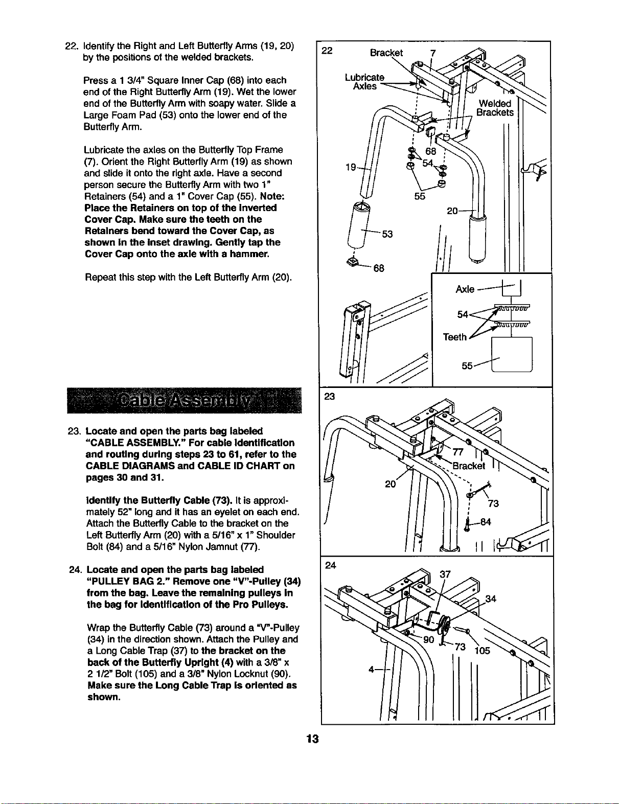
22. Identify the Rightand Left ButterflyArms (19, 20)
by the positions ofthe weldedbrackets.
Press a 1 3/4" Square Inner Cap (68) intoeach
end of the Right ButterflyArm (19). Wet the lower
end of the Butterfly Arm withsoapy water. Slide a
Large Foam Pad (53) onto the lower end of the
Butterfly Arm.
Lubricatethe axles on the Butterfly Top Frame
(7). Orient the Right ButterflyArm (19) as shown
and slide it onto the right axle. Have a second
person secure the Butterfly Arm with two 1"
Retainers (54) and a 1" Cover Cap (55). Note:
Place the Retainers on top of the Inverted
Cover Cap. Make sure the teeth on the
Retainers bend toward the Cover Cap, as
shown In the Inset drawing. Gently tap the
Cover Cap onto the axle with a hammer.
Repeat this step with the Left Butterfly Arm (20).
23. Locate and open the parts beg labeled
"CABLE ASSEMBLY." For cable Identification
and routing during steps 23 to 61, refer to the
CABLE DIAGRAMS and CABLE ID CHART on
pages 30 and 31.
Identify the Butterfly Cable (73). It isapproxi-
mately 52"long and ithas an eyelet on each end.
Attachthe ButterflyCable to the bracket on the
Left ButterflyArm (20) with a 5/16" x 1"Shoulder
Bolt (84) and a 5/16" NylonJamnut(77).
24. Locate and open the parts bag labeled
"PULLEY BAG 2." Remove one "V"-Pulley (34)
from the bag. Leave the remalnlng pulleys In
the bag for IdentlflcaUon of the Pro Pulleys.
Wrap the ButterflyCable (73) around a =V"-Pulley
(34) inthe direction shown.Attach the Pulleyand
a Long Cable Trap (37) tothe bracket on the
back of the Butterfly Upright (4) with a 3/8" x
2 1/2"Bolt (105) and a 3/8" Nylon Locknut(90).
Make sure the Long Cable Trap Is oriented as
shown.
22
20---
=_==,
53
:/I
68
Teet_hif
55_
23
77
"-..'Bracket
Jh ,.J,,,
24
13
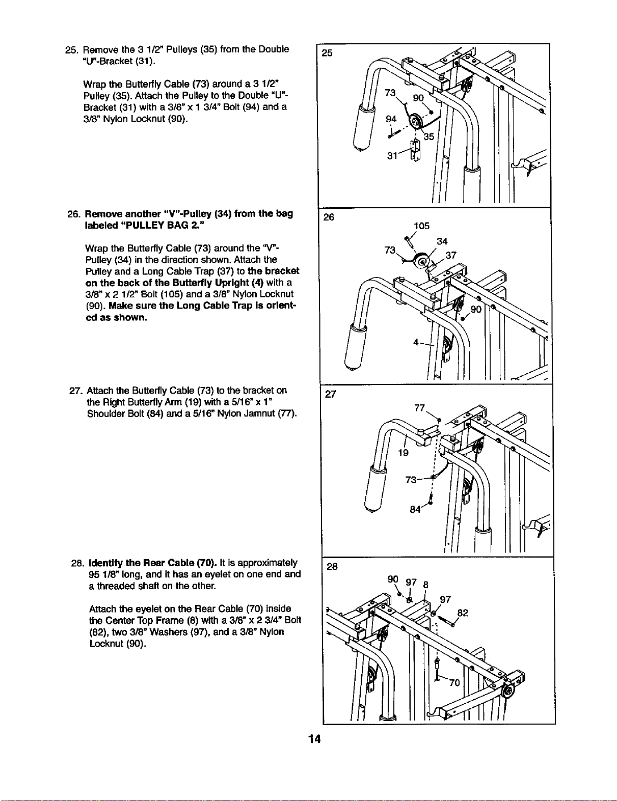
25. Remove the 3 1/2" Pulleys(35) fromthe Double
"U"-Bracket (31).
Wrap the ButterflyCable (73) arounda 3 1/2"
Pulley (35). Attach the Pulley tothe Double"U"-
Bracket (31) with a 3/8" x 1 314"Bolt (94) and a
3/8" Nylon Locknut (90).
26. Remove another "V"-Pulley (34) from the bag
labeled "PULLEY BAG 2."
Wrap the Butterfly Cable (73) aroundthe "4"-
Pulley (34) in the directionshown.Attach the
Pulleyand a Long Cable Trap (37) tothe bracket
on the back of the Butterfly Upright (4) with a
3/8" x 2 1/2" Bolt(105) anda 3/8" NylonLocknut
(90). Make sure the Long Cable Trap Is orient-
ed as shown.
27. Attach the ButterflyCable (73) tothe bracket on
the RightButterflyArm (19) witha 5/16"x 1"
ShoulderBolt(84) and a 5/16" NylonJamnut(77).
28. Identify the Rear Cable (70). Itis approximately
95 1/8" long.and it has an eyelet on one end and
a threaded shafton the other.
Attachthe eyelet on the Rear Cable (70) inside
the Center Top Frame (8) with a 3/8" x 23/4" Bolt
(82), two 3/8" Washers (97), and a 3/8" Nylon
Locknut (90).
25
26
105
34
73,, /37
27
77
28
90
8
97
82
14
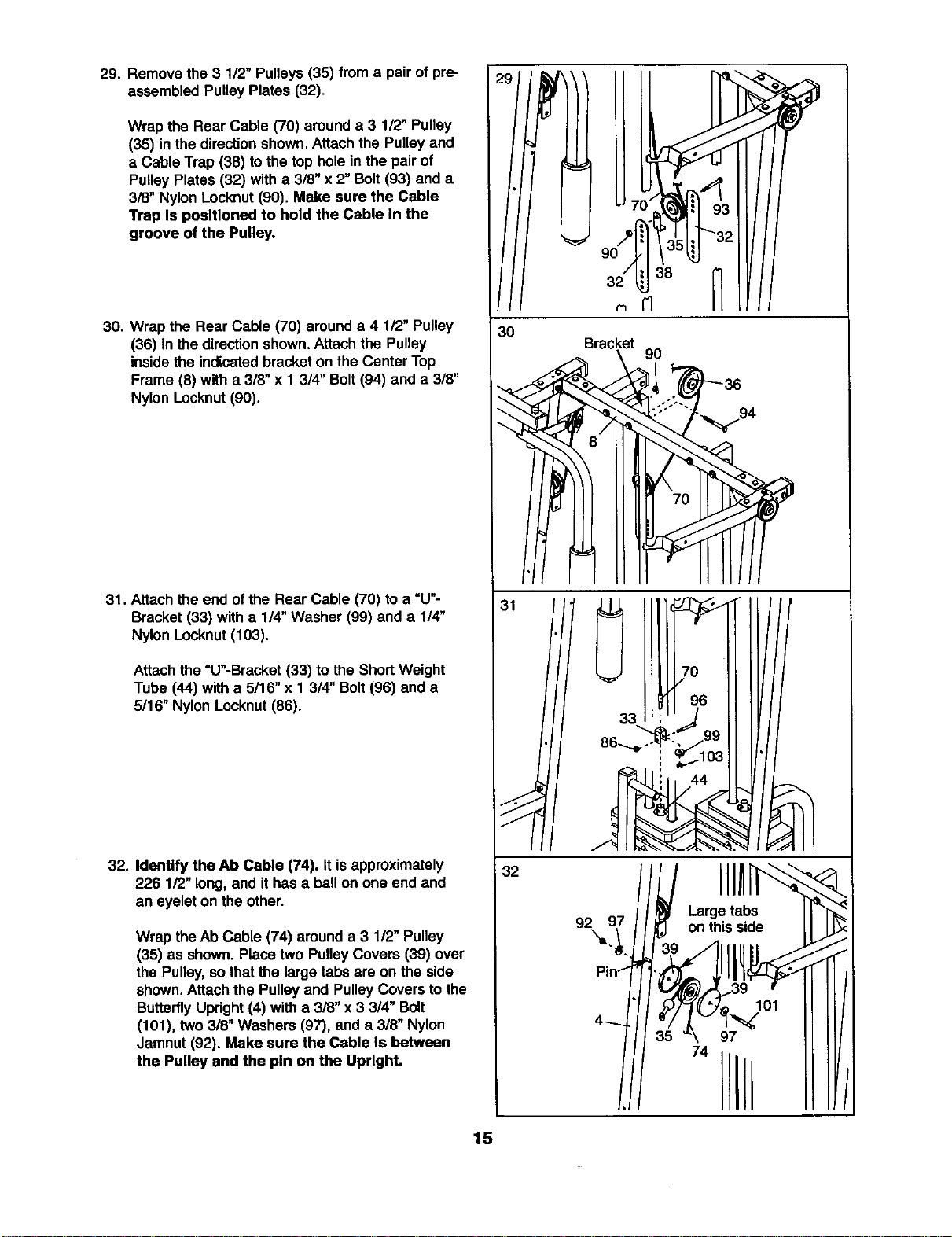
29. Remove the 3 112"Pulleys(35) froma pair of pre-
assembled Pulley Plates (32).
Wrap the Rear Cable (70) arounda 3 1/2" Pulley
(35) in the direction shown. Attach the Pulley and
a Cable Trap (38) to the top hole in the pair of
Pulley Plates (32) with a 3/8" x 2" Bolt (93) and a
3/8" Nylon Locknut (90). Make sure the Cable
Trap Is positioned to hold the Cable In the
groove of the Pulley.
30. Wrap the Rear Cable (70) arounda 4 1/2" Pulley
(36) in the directionshown.Attach the Pulley
inside the indicated bracket on the Center Top
Frame (8) with a 3/8" x 1 3/4" Bolt (94) and a 3/8"
Nylon Locknut (90).
31. Attach the end of the Rear Cable (70) to a "U"-
Bracket (33) with a 1/4"Washer (99) and a 1/4"
Nylon Locknut (103).
Attach the "U"-Bracket (33) to the Short Weight
Tube (44) with a 5/16" x 1 3/4" Bolt (96) and a
5/16" Nylon Locknut (86).
32. Identify the Ab Cable (74). It is approximately
226 1/2" long,and it has a ball on one end and
an eyelet on the other.
Wrap the Ab Cable (74) around a 3 1/2" Pulley
(35) as shown. Placetwo PulleyCovers (39) over
the Pulley, sothat the large tabs are on the side
shown.Attach the Pulley and Pulley Covers to the
Butterfly Updght (4) with a 3/8" x 3 3/4" Bolt
(101), two 3/8" Washers (97), and a 3/8" Nylon
Jamnut (92). Make sure the Cable Is between
the Pulley end the pin on the Upright.
30
Bracket
9O
,!. 3o
/
32
92_9_ //_ 9 onthis side
15
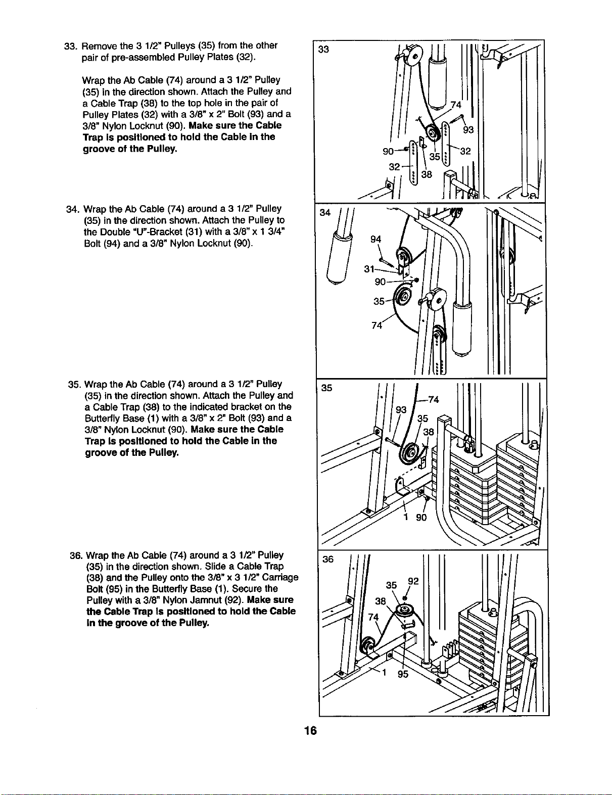
33. Remove the 3 112"Pulleys (35) from the other
pairof pre-assembled Pulley Plates (32).
Wrap the Ab Cable (74) arounda 3 112"Pulley
(35) in the directionshown.Attach the Pulley and
a Cable Trap (38) to the top holein the pair of
PulleyPlates (32) with a 3/8" x 2"Bolt(93) and a
318"Nylon Locknut(90). Make sure the Cable
Trap Is positioned to hold the Cable In the
groove of the Pulley.
34. Wrap the Ab Cable (74) arounda 3 1/2" Pulley
(35) in the directionshown.Attach the Pulleyto
the Double"U"-Bracket (31) with a 3/8" x 1 3/4"
Bolt(94) and a 3/8" Nylon Locknut(90).
35. Wrap the Ab Cable (74) arounda 3 1/2" Pulley
(35) in the directionshown,Attach the Pulleyand
a Cable Trap (38) to the indicatedbracketon the
ButterflyBase (1) with a 3/8" x 2" Bolt(93) and a
3/8" Nylon Locknut(90). Make sure the Cable
Trap Is positioned to hold the Cable In the
groove of the Pulley.
36. Wrap theAb Cable (74) arounda 3 1/2" Pulley
(35) in the directionshown. Slide a Cable Trap
(38) and the Pulleyonto the 3/8" x 3 1/2" Carriage
Bolt(95) inthe ButterflyBase (1). Secure the
Pulleywith a 3/8" NylonJamnut (92). Make sure
the Cable Trap Is positioned to hold the Cable
In the groove of the Pulley.
35
1 90
16
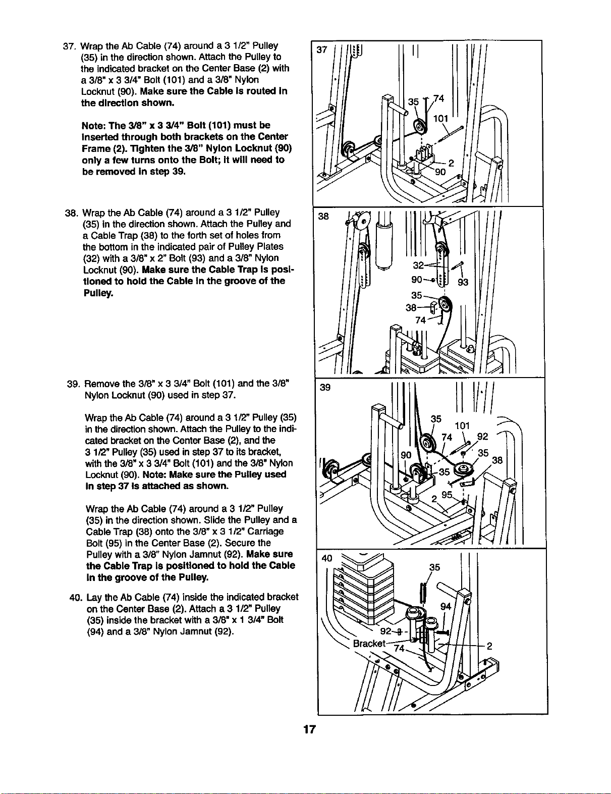
37. Wrap the Ab Cable (74) arounda 3 1/2" Pulley
(35) in the directionshown.Attach the Pulley to
the indicatedbracket on the Center Base (2) with
a 3/8" x 3 3/4" Bolt (101) and a 318"Nylon
Locknut (90). Make sure the Cable Is routed In
the direction shown.
Note: The 3/8" x 3 3/4" Bolt (101) must be
Inserted through both brackets on the Center
Frame (2). Tighten the 3/8" Nylon Locknut (90)
only a few turns onto the Bolt; It will need to
be removed In step 39.
38. Wrap the Ab Cable (74) around a 3 1/2" Pulley
(35) in the directionshown.Attachthe Pulleyand
a Cable Trap (38) to the forthset of holesfrom
thebottomin the indicatedpair of PulleyPlates
(32) with a 3/8" x 2"Bolt (93) and a 318"Nylon
Locknut(90). Make sure the Cable Trap Is posi-
tioned to hold the Cable In the groove of the
Pulley.
39. Remove the 3/8" x 3 3/4" Bolt (101) and the 3/8"
Nylon Locknut (90) used in step 37.
Wrap the Ab Cable (74) arounda 3 1/2" Pulley(35)
in the directionshown.Attach the Pulleyto theindi-
catedbracketon the CenterBase (2), and the
3 1/2" Pulley(35) used in step37 to itsbracket,
withthe 3i8" x 3 3/4" Bolt (101) and the 3/8" Nylon
Locknut(90). Note: Make sure the Pulley used
In step 37 Is attached as shown.
Wrap the At)Cable (74) around a 3 1/2" Pulley
(35) in the directionshown. Slidethe Pulley and a
CableTrap (38) ontothe 3/8" x 3 1/2" Carriage
Bolt(95) in the Center Base (2). Secure the
Pulleywith a 3/8" Nylon Jamnut (92). Make sure
the Cable Trap Is poslUoned to hold the Cable
In the groove of the Pulley.
40. Laythe Ab Cable (74) inside the indicatedbracket
on the Center Base (2). Attach a 3 112"Pulley
(35) insidethe bracketwith a 3/8" x I 3/4" Bolt
(94) and a 3/8" Nylon Jamnut (92).
37. i 351174101"
38
39
35
17
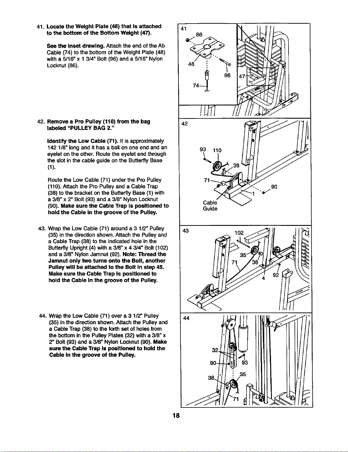
41. Locate the Weight Plate (48) that Is attached
to the bottom of the Bottom Weight (47).
See the Inset drawing. Attachthe end of theAb
Cable (74) to the bottom of the Weight Plate (48)
with a 5/16" x 1 3/4" Bolt(96) anda 5/16" Nylon
Locknut(86).
42. Remove a Pro Pulley (110) from the bag
labeled "PULLEY BAG 2."
Identify the Low Cable (71). It isapproximately
142 1/8" longand it has a ballon one end and an
eyelet on the other. Routethe eyelet end through
the slot in the cable guide on the ButterflyBase
(1).
Routethe Low Cable (71) under the Pro Pulley
(110). Attachthe Pro Pulleyand a Cable Trap
(38) to the bracket on the ButterflyBase (1) with
a 3/8" x 2"Bolt (93) and a 318"NylonLocknut
(90). Make sure the Cable Trap Is positioned to
hold the Cable In the groove of the Pulley.
43. Wrap the Low Cable (71) arounda 3 112"Pulley
(35) in the directionshown.Attach the Pulleyand
a Cable Trap (38) to the indicatedhole in the
ButterflyUpdght(4) with a 3/8" x 4 3/4" Bolt(102)
and a 3/8" NylonJamnut (92). Note: Thread the
Jamnut only two turns onto the Bolt, another
Pulley will be attached to the Bolt In step 45.
Make sure the Cable Trap Is positioned to
hold the Cable In the groove of the Pulley.
44. Wrap the Low Cable (71) over a 3 1/2" Pulley
(35) in the dire_ion shown.Attach the Pulleyand
a Cable Trap (38) tothe forthset of holesfrom
the bottominthe Pulley Plates (32) with a 3/8" x
2" Bolt(93) and a 3/8" Nylon Locknut(90). Make
sure the Cable "l_ap Is positioned to hold the
Cable In the groove of the Pulley.
41
42
93 110
9O
Cable
Guide
43 102
44
90-
! 35
18
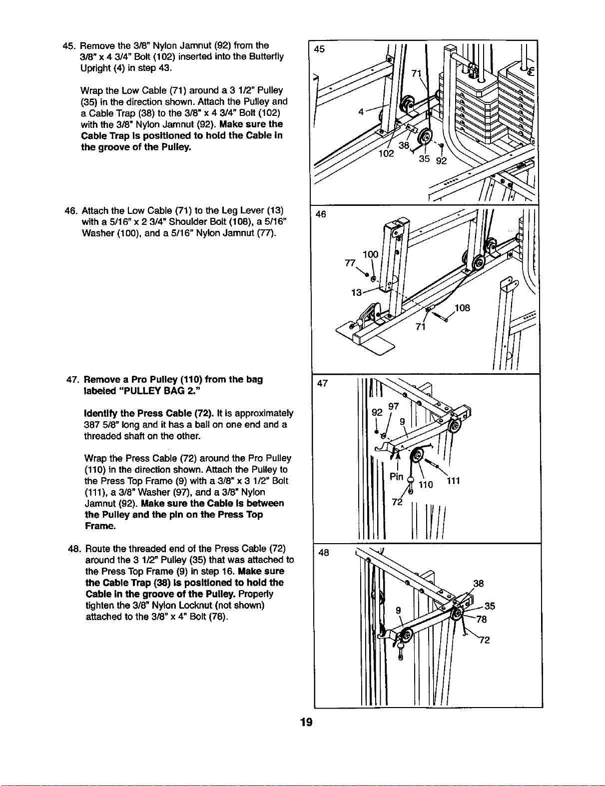
45. Remove the 3/8" Nylon Jamnut (92) from the
3/8" x 4 3/4" Bolt(102) inserted intothe Butterfly
Upright(4) in step43.
Wrap the Low Cable (71) arounda 3 1/2" Pulley
(35) in the directionshown.Attach the Pulley and
a Cable Trap (38) to the 3/8" x 4 3/4" Bolt (102)
with the 3/8" Nylon Jamnut (92). Make sure the
Cable Trap Is positioned to hold the Cable in
the groove of the Pulley.
46. Attach the Low Cable (71) to the Leg Lever (13)
with a 5/16" x 2 314"Shoulder Bolt (108), a 5/16"
Washer (100), and a 5/16" NylonJamnut (77).
47. Remove a Pro Pulley (110) from the bag
labeled "PULLEY BAG 2."
Identify the Press Cable (72). It isapproximately
387 5/8" longand ithas a ballon one end and a
threaded shafton the other.
Wrap the PressCable (72) aroundthe Pro Pulley
(110) in the directionshown.Attach the Pulley to
the PressTopFrame (9) with a 3/8" x 3 112"Bolt
(111), a 3/8" Washer (97), and a 3/8" Nylon
Jamnut (92). Make sure the Cable Is between
the Pulley and the pin on the Press Top
Frame.
48. Route thethreaded end of the Press Cable (72)
aroundthe 3 112"Pulley(35) that was attached to
the PressTop Frame (9) in step 16. Make sure
the Cable Trap (38) Is positioned to hold the
Cable In the groove of the Pulley. Properly
tightenthe 3/8" Nylon Locknut(not shown)
attached to the 3/8" x 4" Bolt (78).
46
47
48
77
100
\
71
/II IH
38
19
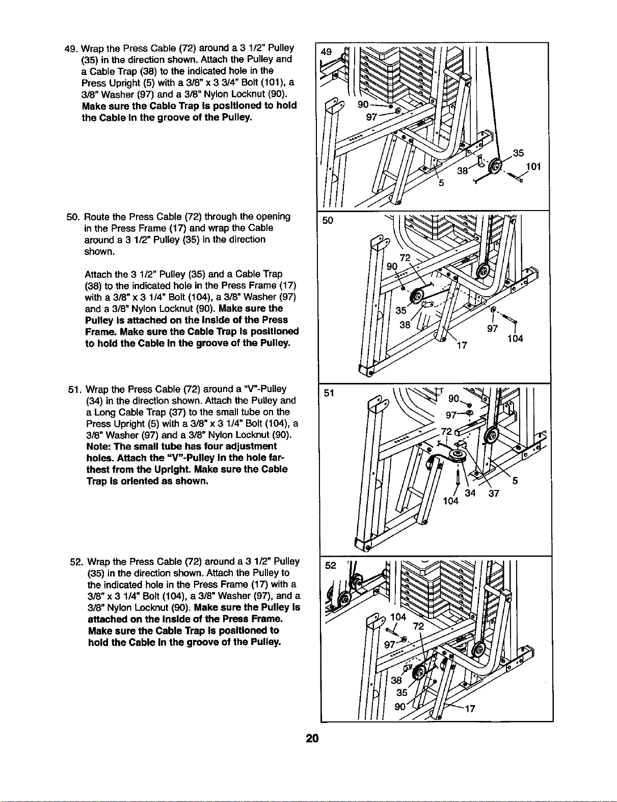
49. Wrap the Press Cable (72) arounda 3 1/2" Pulley
(35) in the direction shown. Attach the Pulley and
a Cable Trap (38) to the indicated hole in the
Press Upright (5) with a 3/8" x 3 3/4" Bolt (101), a
3/8" Washer (97) and a 3/8" Nylon Locknut (90).
Make sure the Cable Trap Is positioned to hold
the Cable In the groove of the Pulley,
50. Route the Press Cable (72) throughthe opening
in the Press Frame (17) and wrap the Cable
arounda 3 1/2" Pulley (35) inthe direction
shown.
Attach the 3 112"Pulley (35) and a Cable Trap
(38) to the indicatedhole inthe Press Frame (17)
witha 3/8" x 3 1/4" Bolt (104), a 3/8" Washer (97)
and a 3/8" Nylon Locknut (90). Make sure the
Pulley Is attached on the Inside of the Press
Frame. Make sure the Cable Trap Is positioned
to hold the Cable In the groove of the Pulley.
51. Wrap the Press Cable (72) around a "V"-Pulley
(34) inthe direction shown.Attach the Pulleyand
a Long Cable Trap (37) to the small tube on the
Press Upright (5) with a 318"x 3 1/4" Bolt (104), a
3/8" Washer (97) and a 318"Nylon Locknut (90).
Note: The small tube has four adjustment
holes. Attach the "V"-Pulley In the hole far-
thest from the Upright. Make sure the Cable
Trap Is oriented as shown.
52. Wrap the PressCable (72) around a 3 1/2" Pulley
(35) in the directionshown.Attachthe Pulley to
the indicated hole in the Press Frame (17) with a
3/8" x 3 1/4" Bolt (104), a 3/8" Washer (97), and a
3/8" Nylon Locknut (90). Make sure the Pulley Is
attached on the Inside of the Press Frame.
Make sure the Cable Trap Is positioned to
hold the Cable In the groove of the Pulley.
51
34 37
104
20
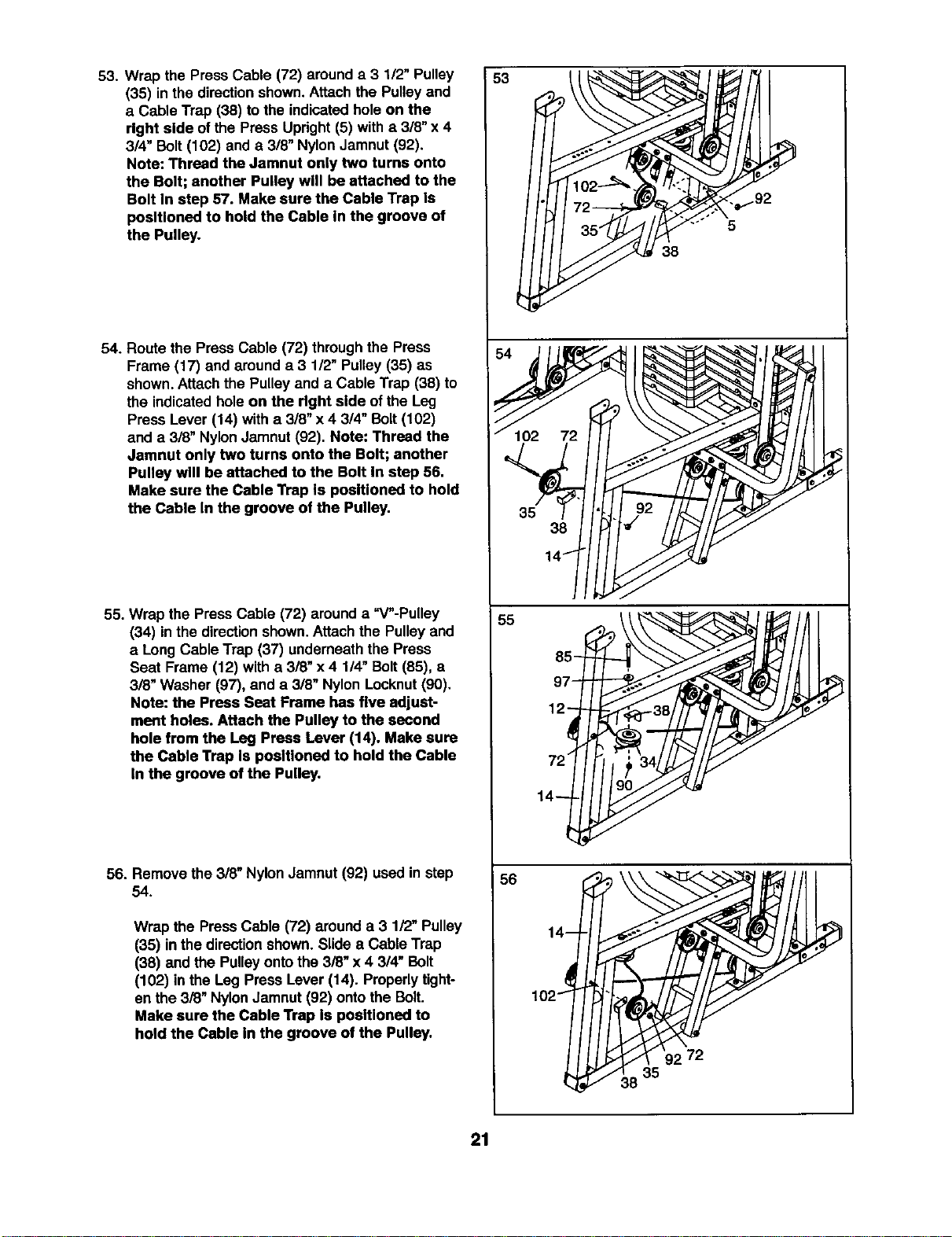
53. Wrap the PressCable (72) arounda 3 1/2" Pulley
(35) in the directionshown.Attach the Pulleyand
a Cable Trap (38) to the indicatedhole on the
right side of the Press Upright(5) witha 3/8" x 4
3/4" Bolt(102) and a 3/8" Nylon Jamnut (92).
Note: Thread the Jamnut only two turns onto
the Bolt; another Pulley will be attached to the
Bolt In step 57. Make sure the Cable Trap Is
positioned to hold the Cable In the groove of
the Pulley.
54. Route the Press Cable (72) throughthe Press
Frame (17) and arounda 3 1/2" Pulley (35) as
shown. Attachthe Pulley and a Cable Trap (38) to
the indicatedhole on the right side ofthe Leg
Press Lever (14) with a 318"x 4 3/4" Bolt (102)
and a 3/8" NylonJamnut (92). Note: Thread the
Jamnut only two turns onto the Bolt; another
Pulley will be attached to the Bolt In step 56.
Make sure the Cable "NapIs poslUoned to hold
the Cable In the groove of the Pulley.
55. Wrap the Press Cable (72) arounda =V"-Pulley
(34) inthe direction shown.Attach the Pulley and
a Long Cable Trap (37) underneaththe Press
Seat Frame (12) with a 318"x4 114"Bolt (85), a
3/8" Washer (97), and a 3/8" Nylon Locknut(90).
Note: the Press Seat Frame has five adjust-
ment holes. Attach the Pulley to the second
hole from the Leg Press Lever (14). Make sure
the Cable Trap Is positioned to hold the Cable
In the groove of the Pulley,
56. Remove the 318"Nylon Jamnut (92) used in step
54.
Wrap the PressCable (72) arounda 3 1/2" Pulley
(35) inthe directionshown. Slide a Cable Trap
(38) and the Pulleyonto the 3/8" x 4 3/4" Bolt
(102) in the Leg Press Lever (14). Properlytight-
en the 3/8" Nylon Jamnut (92) onto the Bolt.
Make sure the Cable Trap Is positioned to
hold the Cable In the groove of the Pulley.
53
5
38
54 _ • e
38
14"
85
97
12
14
56
14-
102-_
_38 35
21
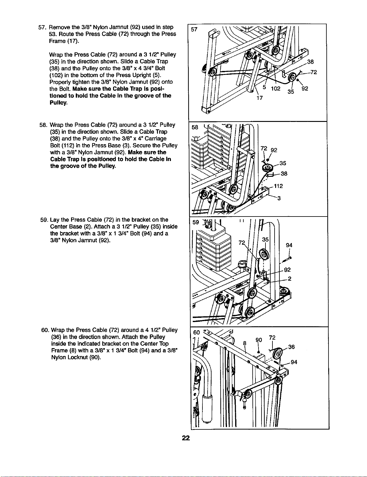
57. Remove the 3/8" Nylon Jamnut (92) used in step
53. Routethe PressCable (72) throughthe Press
Frame (17).
Wrap the Press Cable (72) arounda 3 1/2" Pulley
(35) in the directionshown. Slide a Cable Trap
(38) and the Pulleyontothe 3/8" x 4 314"Bolt
(102) in the bottomofthe Press Updght (5).
Properlytightenthe 3/8" NylonJamnut (92) onto
the Bolt. Make sure the Cable Trap Is posi-
tioned to hold the Cable In the groove of the
Pulley.
58. Wrapthe PressCable (72) arounda 3 112"Pulley
(35) in the directionshown. Slidea Cable Trap
(38) and the Pulleyontothe3/8" x 4"Carriage
Bolt(112) in the Press Base (3). Secure the Pulley
witha 318"Nylon Jamnut (92). Make sure the
Cable Trap Is positioned to hold the Cable In
the groove of the Pulley.
59. Lay the PressCable (72) in the bracketon the
Center Base (2). Attach a 3 1/2" Pulley(35) inside
the bracketwith a 3/8" x 1 3/4" Bolt (94) and a
318"NylonJamnut (92).
60. Wrap the Press Cable (72) around a 4 112"Pulley
(36) inthe directionshown.Attach the Pulley
insidethe indicatedbracketon the Center Top
Frame (8) with a 3/8" x 1 3/4" Bolt (94) and a 3/8"
Nylon Locknut(90).
57
38
2
W 1023'592
17
92
.112
90 72
22
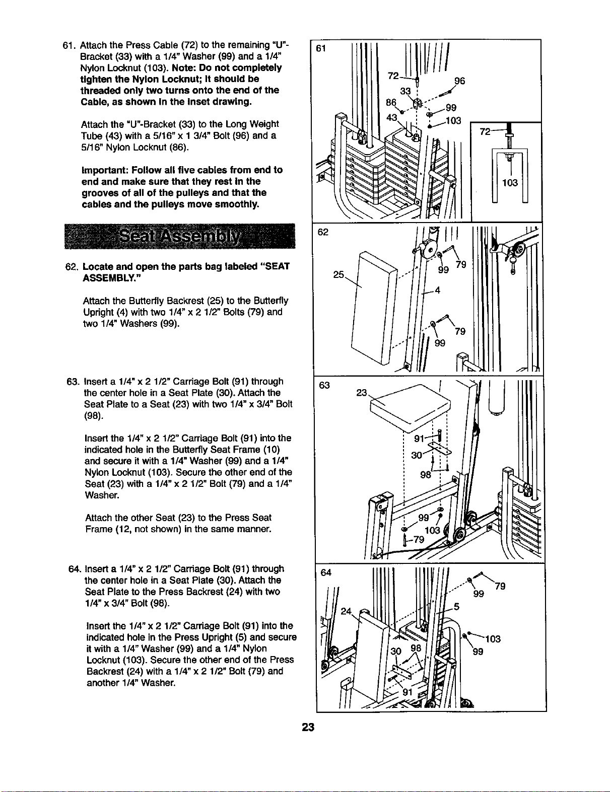
61. Attach the PressCable (72) tothe remaining=U"-
Bracket (33) with a 1/4" Washer (99) anda 1/4"
Nylon Locknut(103). Note: Do not completely
Ughten the Nylon Locknut; It should be
threaded only two turns onto the end of the
Cable, as shown In the Inset drawing•
Attachthe =U"-Bracket (33) to the LongWeight
Tube (43) with a 5116"x 1 3/4" Bolt(96) and a
5116"Nylon Locknut(86).
Important: Follow all five cables from end to
end and make sure that they rest In the
grooves of all of the pulleys and that the
cables and the pulleys move smoothly.
62. Locate and open the parts bag labeled "SEAT
ASSEMBLY."
Attachthe ButterflyBackrest (25) to the Butterfly
Upright(4) with two 114"x 2 1/2" Bolts(79) and
two 1/4" Washers (99).
63. Insert a 1/4"x 2 112"Carriage Bolt (91) through
the center hole in a Seat Plate (30). Attach the
Seat Plate to a Seat (23) with two 1/4"x 3/4" Bolt
(98).
Insertthe 1/4" x 2 112"Carriage Bolt (91) intothe
indicatedhole in the ButterflySeat Frame (10)
and secure it with a 1/4" Washer (99) and a 1/4"
Nylon Locknut(103). Secure the other end of the
Seat (23) with a 1/4" x 2 1/2" Bolt (79) and a 1/4"
Washer.
Attachthe other Seat (23) to the Press Seat
Frame (12, not shown) inthe same manner.
64. Inserta 1/4" x 2 1/2" Carriage Bolt(91) through
the center holein a Seat Plate (30). Attachthe
Seat Plate to the Press Backrest (24) with two
1/4" x 3/4" Bolt(98).
Insert the 114"x 2 112"Carriage Bolt (91) intothe
indicatedholein the Press Upright(5) and secure
itwith a 114"Washer (99) and a 1/4" Nylon
Locknut(103). Secure the otherend of the Press
Backrest(24) with a 1/4"x 2 112"Bolt(79) and
another 114"Washer.
62
25_
63
64
.o
o."
////
96
....""_'_79
99
23
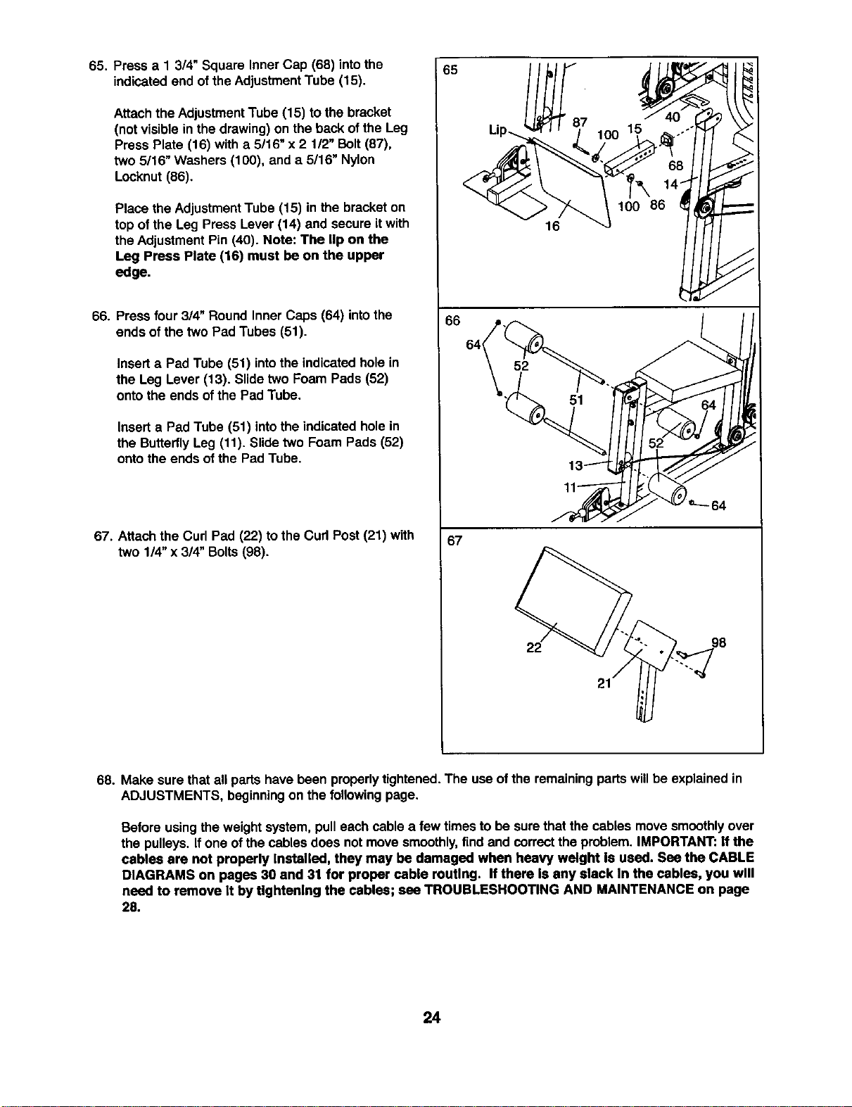
65. Press a 1 3/4" Square Inner Cap (68) intothe
indicatedend ofthe Adjustment Tube (15).
Attach the AdjustmentTube (15) to the bracket
(not visiblein the drawing)on the backof the Leg
Press Plate (18) with a 5/16" x 2 1/2" Bolt(87),
two 5/16" Washers (100), and a 5/16" Nylon
Locknut (86).
Place the AdjustmentTube (15) in the bracketon
top of the Leg Press Lever (14) and secure itwith
the AdjustmentPin (40). Note: The lip on the
Leg Press Plate (16) must be on the upper
edge.
66. Press four 3/4" Round Inner Caps (64) intothe
ends of the two Pad Tubes (51).
Inserta Pad Tube (51) intothe indicatedhole in
the Leg Lever (13). Slide two Foam Pads (52)
onto the ends ofthe PadTube.
Insert a Pad Tube (51) intothe indicatedholein
the ButterflyLeg (11). Slidetwo Foam Pads (52)
onto the ends of the Pad Tube.
67. Attach the Curl Pad (22) tothe Curl Post (21) with
two 1/4"x 3/4" Bolts (98).
65
66
67
52
16
lO0 lI
100 86
14
98
68. Make sure thatall parts have been properly tightened.The useof the remaining parts willbe explained in
ADJUSTMENTS, beginningon the following page.
Before usingthe weightsystem,pull each cable a few timesto be surethat the cables movesmoothlyover
the pulleys. If one of the cables does not move smoothly,find and correctthe problem. IMPORTANT: If the
cables are not properly Installed, they may be damaged when heavy weight Is used. Sea the CABLE
DIAGRAMS on pages 30 and 31 for proper cable routing. If there Is any slack In the cables, you will
need to remove It by tightening the cables; see TROUBLESHOOTING AND MAINTENANCE on page
28.
24
ADJUSTMENTS
The instructionsbelowdescribe how each part o!the weightsystem can be adjusted. Refer to the exemise
guide accompanyingthis manualto see how the weightsystem shouldbe set up for each exercise.IMPOR-
TANT: When using an accessory, make sure It Is In the cor_=ct starting position for the exercise to be
performed. If there Is any slack In the cables or chain as an exercise Is performed, the effecUveness of
the exercise will be reduced.
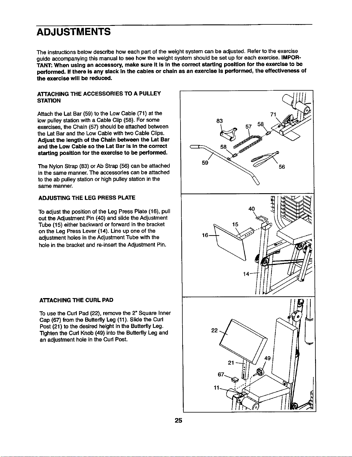
ATTACHING THE ACCESSORIES TO A PULLEY
STATION
Attachthe I_atBar (59) tothe Low Cable (71) at the
low pulleystationwith a Cable Clip (58). For some
exercises,the Chain (57) shouldbe attachedbetween
the LatBar and the Low Cable withtwoCable Clips.
Adjust the length of the Chain between the Lat Bar
end the Low Cable so the Lat Bar Is In the correct
starting position for the exercise to be performed.
The Nylon Strap (83) or Ab Strap (56) can be attached
in the same manner.The accessoriescan be attached
tothe ab pulleystationor highpulleystationinthe
same manner.
ADJUSTING THE LEG PRESS PLATE
To adjust the positionof the Leg Press Plate (16), pull
out theAdjustmentPin (40) and slide theAdjustment
Tube (15) eitherbackward or forward inthe bracket
on the Leg Press Lever (14). Line up one ofthe
adjustmentholes in the AdjustmentTube with the
hole in the bracketand re-insertthe AdjustmentPin.
ATTACHING THE CURL PAD
To usethe Curl Pad (22), removethe 2"Square Inner
Cap (67) from the ButterflyLeg (11). Slidethe Curl
Post (21) to the desired height inths ButterflyLeg.
Tightenthe Curl Knob (49) intothe ButterflyLeg and
an adjustment holein the Curl Post.
83
59
22
15
57
71
40
25
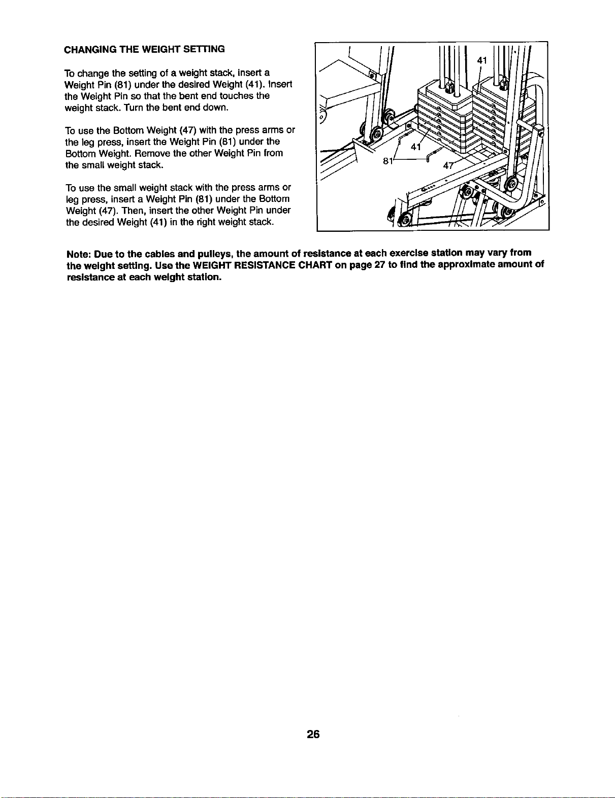
CHANGING THE WEIGHT SETTING
To change the settingof a weightstack, insert a
Weight Pin (81) under the desired Weight (41). insert
the Weight Pin so that the bent end touchesthe
weight stack.Turn the bent end down.
To use the BottomWeight (47) withthe press arms or
the leg press, insertthe Weight Pin (81) under the
BottomWeight. Remove the otherWeight Pin from
the small weight stack.
To use the small weight stack withthe press arms or
leg press, inserta Weight Pin (81) underthe Bottom
Weight (47). Then, insertthe other Weight Pin under
the desired Weight (41) in the rightweight stack.
Note: Due to the cables and pulleys, the amount of resistance at each exercise station may vary from
the weight setting. Use the WEIGHT RESISTANCE CHART on page 27 to find the approximate amount of
resistance at each weight station.
26
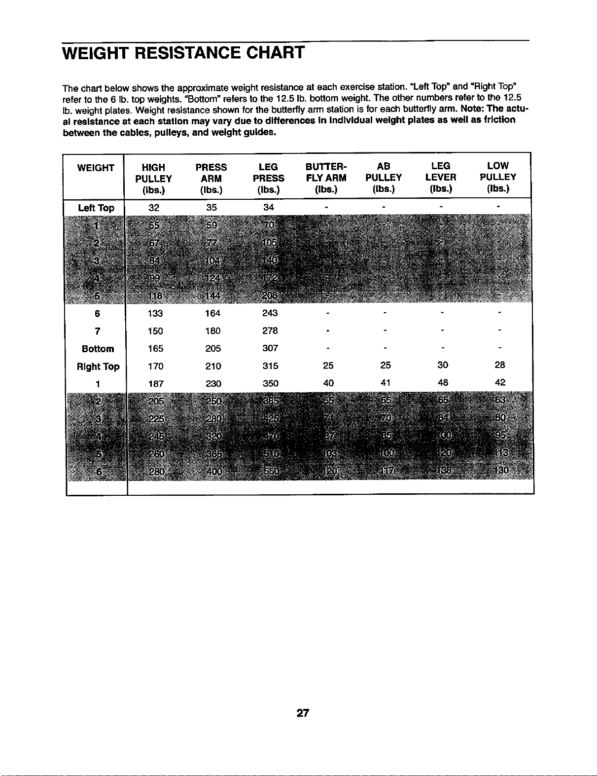
WEIGHT RESISTANCE CHART
The chart below shows the approximateweightresistanceat each exercise station."Left Top"and =RightTop"
refer to the 6 lb. top weights. =Bottom" refers tothe 12.5 lb. bottomweight. The othernumbers refer to the 12,5
lb.weight plates. Weight resistanceshownfor the butterflyarm stationisfor each butterflyarm. Note: The actu-
al resistance at each station may vary due to differences In Individual weight plates as well as friction
between the cables, pulleys, and weight guides.
WEIGHT HIGH PRESS LEG BUTTER- AB LEG LOW
PULLEY ARM PRESS FLY ARM PULLEY LEVER PULLEY
(Ibs.) (Ibs.) (Ibs.) (Ibs.) (Ibs.) (Ibs.) (Ibs.)
Le_Top 32 35 34
6
7
Bottom
RlghtTop
1
133 164 243
150 180 278
165 205 307
170 210 315 25
187 230 350 40
25 30 28
41 48 42
27
TROUBLESHOOTING AND MAINTENANCE
Make sure all parts are properlytightened each time you usethe weightsystem. Replace any wornpartsimmedi-
ately.The weight system can be cleaned using a damp clothand mild non-abrasive detergent. Do not use solvents.
TIGHTENING THE CABLES
Woven cable, the type of cable used on the weightsystem, can stretchslightlywhen it isfirst used. If there is
slack in the cables before resistanceisfelt, the cables shouldbe tightened.Slack can be removedfrom the
cables in several differentways.
When you are tighteningthe cables, note that they are linked intotwo distinct groups.The Rear Cable (70), the
Low Cable (71), the Butterfly Cable (73), and the Ab Cable (74) are all connected to the small weight stack. All
three cables will be tightened by tightening the Rear Cable at the small weight stack, or by adjusting the
3 1/2" Pulleys (35) in either set of Pulley Plates (32).
The Press Cable (72) is attached to the large weight stack. The Press Cable can be tightenedat the large
weight stack or by moving the "V"-Pulleys (34) on the Press Upright (5) and the Press Seat Frame (12).
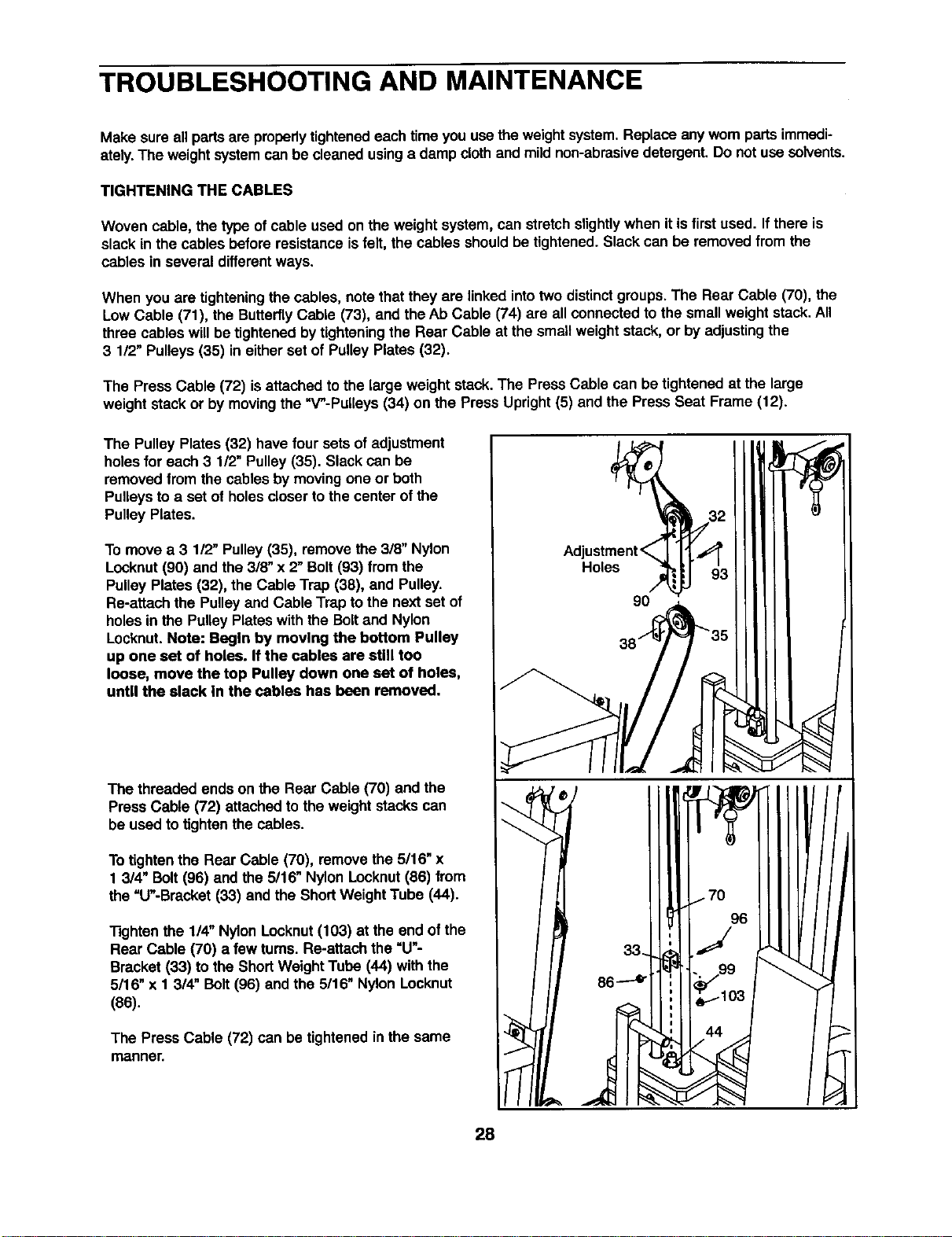
The Pulley Plates (32) have four sets of adjustment
holes for each 3 1/2" Pulley (35). Slack can be
removed from the cables by moving one or both
Pulleys to a set of holes closer to the center of the
Pulley Plates.
To move a 3 112"Pulley (35), remove the 318"Nylon
Locknut(90) and the 318"x 2" Bolt(93) from the
Pulley Plates (32), the Cable Trap (38), and Pulley.
Re-attach the Pulley and Cable Trap to the next set of
holes in the Pulley Plates with the Bolt and Nylon
Locknut.Note: Begin by moving the bottom Pulley
up one set of holes. If the cables are still too
loose, move the top Pulley down one set of holes,
until the slack In the cables has been removed.
The threaded ends on the Rear Cable (70) and the
PressCable (72) attachedto the weight stackscan
be used to tightenthe cables.
To tighten the Rear Cable (70), remove the 5/16" x
1 3/4" Bolt(96) andthe 5/16" NylonLocknut(86) from
the "U"-Bracket(33) and the Short WeightTube (44).
Tightenthe 1/4" Nylon Locknut(103) at the end of the
Rear Cable (70) a few tums. Re-attach the "U"-
Bracket (33) to the ShortWeight Tube (44) withthe
5/16" x 1 3/4" Bolt (96) and the 5/16" NylonLocknut
(86).
The Press Cable (72) can be tightenedinthe same
manner.
9O
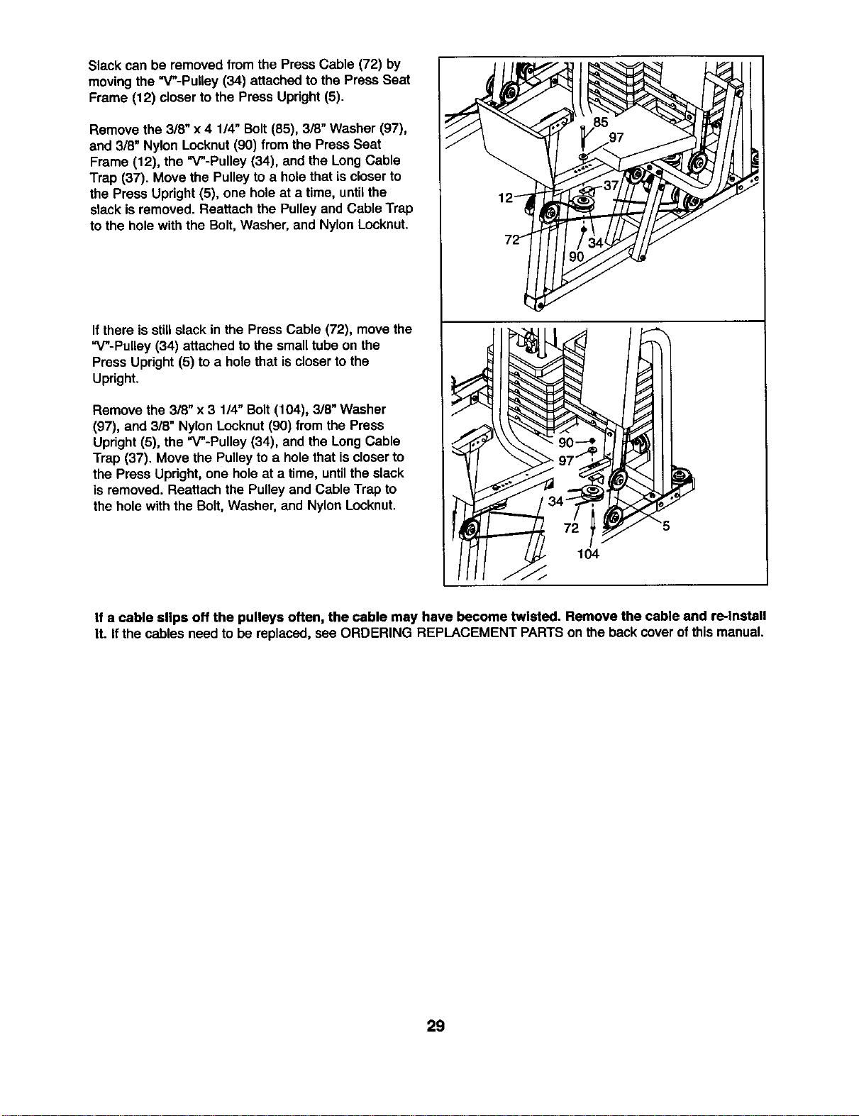
Slack can be removedfrom the Press Cable (72) by
movingthe =V"-Pulley (34) attached to the Press Seat
Frame (12) closerto the Press Upright(5).
Remove the 3/8" x 4 1/4" Bolt(85), 3/8" Washer (97),
and 3/8" Nylon Locknut(90) from the Press Seat
Frame (12), the "V"-Pulley (34), and the LongCable
Trap (37). Move the Pulleyto a holethat iscloserto
the Press Upright (5), one holeat a time, untilthe
slack isremoved. Reattach the Pulley and Cable Trap
to the hole with the Bolt, Washer, and Nylon Locknut.
I{there isstillslack in the Press Cable (72), move the
"V"-PuUey (34) attached to the small tube on the
Press Upright (5) to a hole that is closerto the
Upright.
Remove the 3/8" x 3 114"Bolt(104), 318"Washer
(97), and 3/8" Nylon Locknut(90) from the Press
Updght (5), the "V"-Pulley (34), and the Long Cable
Trap (37). Move the Pulleyto a holethat iscloserto
the Press Upright,one holeat a time, untilthe slack
is removed. Reattach the Pulley and Cable Trap to
the hole with the Bolt, Washer, and Nylon Locknut,
If a cable slips off the pulleys often, the cable may have become twisted. Remove the cable and re-Install
It. If the cables need to be replaced, see ORDERING REPLACEMENT PARTSon the backcover o!this manual.
29
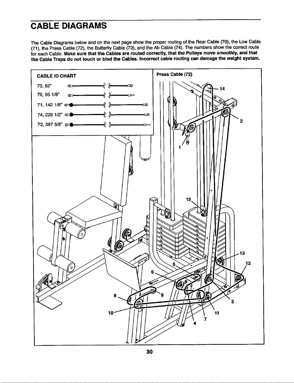
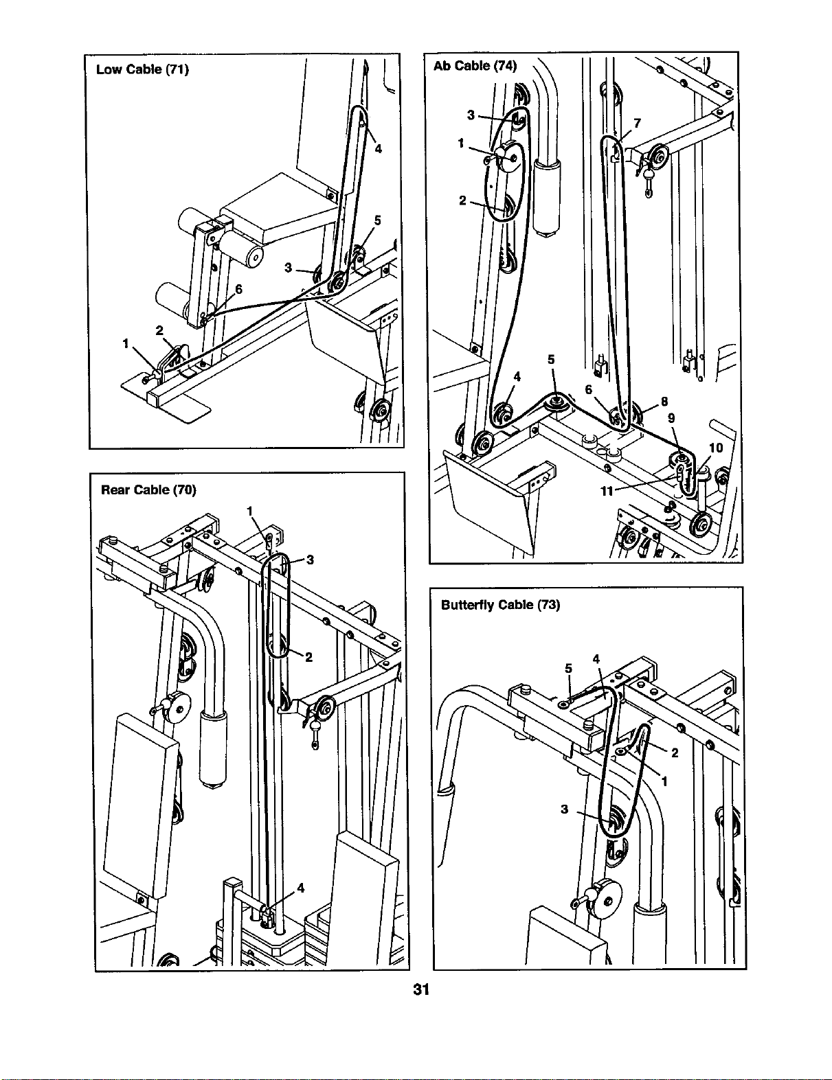
CABLE DIAGRAMS
The Cable Diagrams below and on the next page show the propermutingof the Rear Cable (70), the Low Cable
(71), the Press Cable (72), the ButterflyCable (73), and the Ab Cable (74). The numbers showthe correctroute
for each Cable. Make sure that the Cables are routed correctly, that the Pulleys move smoothly, and that
the Cable Traps do not touch or bind the Cables. Incorrect cable routing can damage the weight system.
I Press Cable (72)
2
12
7
4
3
11
30
Low Cable (71)
2
Rear Cable (70)
1
Butterfly Cable (73)
5
31
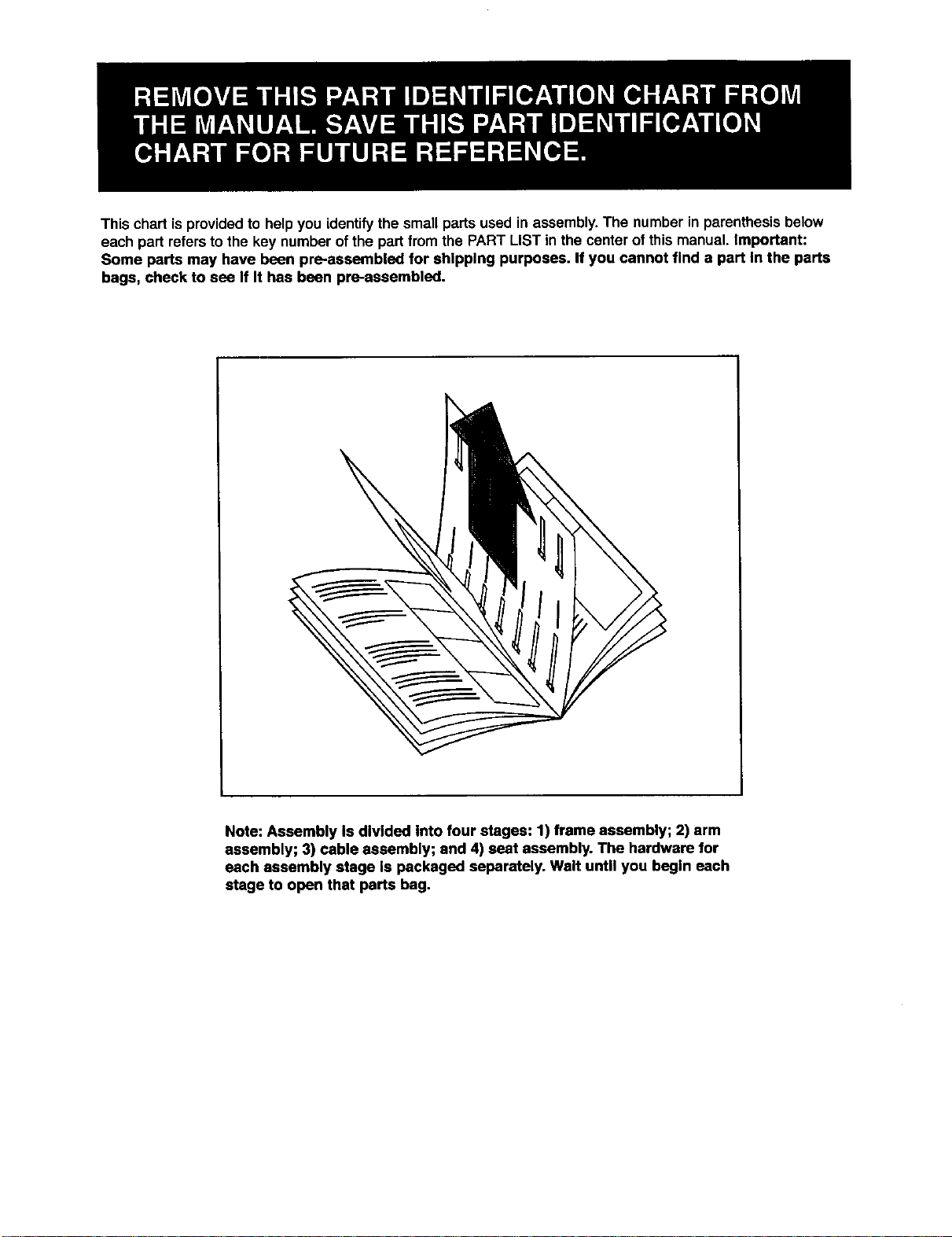
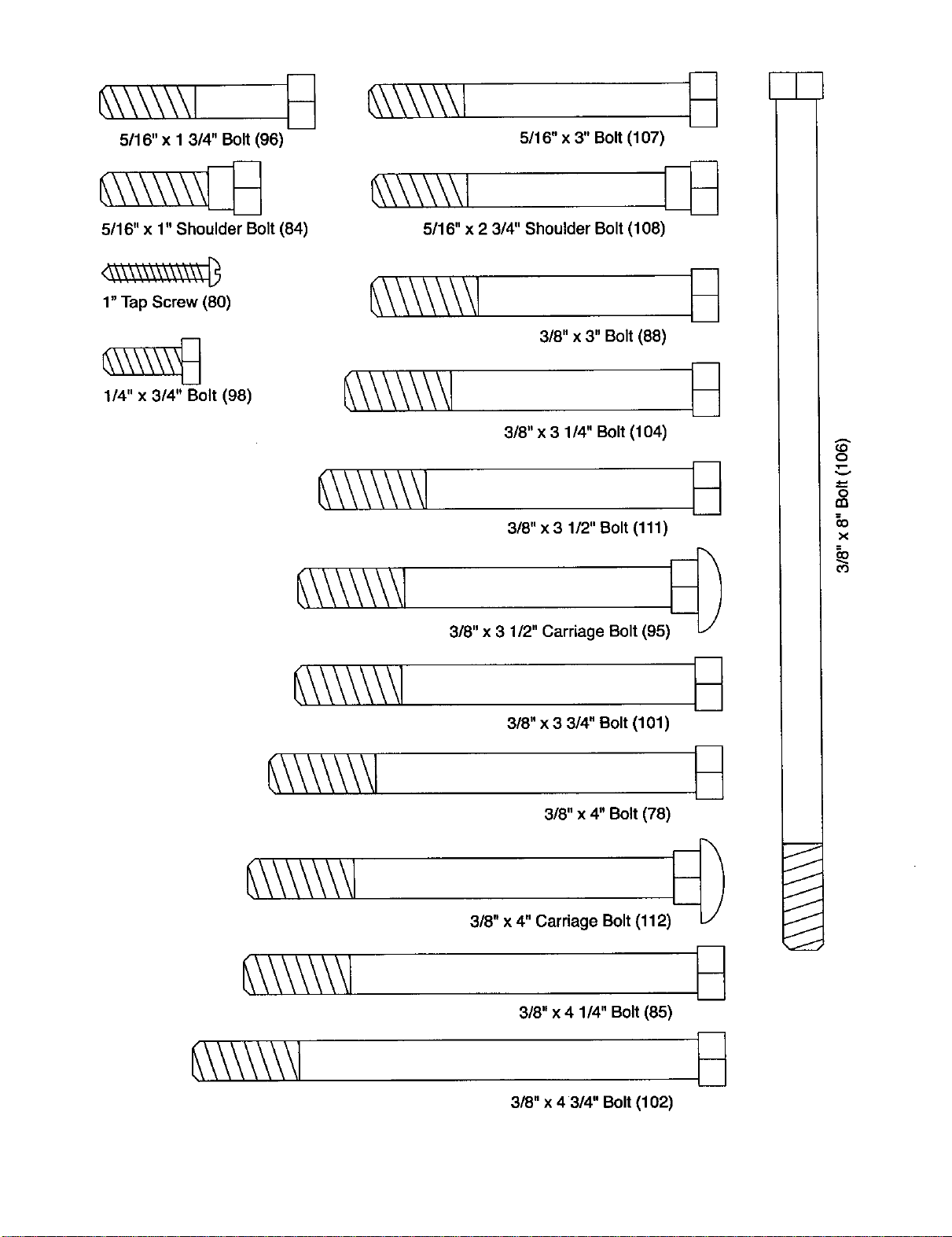
This chart isprovided to help you identifythe small parts used in assembly.The number in parenthesis below
each part refersto the key number ofthe part from the PART LIST in the center of this manual. Important:
Some parts may have been pre-assembled for shipping purposes. If you cannot find a part In the parts
bags, check to sea If It has bean pl_-assembled.
Note: Assembly Is divided into four stages: 1) frame assembly; 2) arm
assembly; 3) cable assembly; and 4) seat assembly. The hardware for
each assembly stage Is packaged separately. Walt until you begin each
stage to open that parts bag.
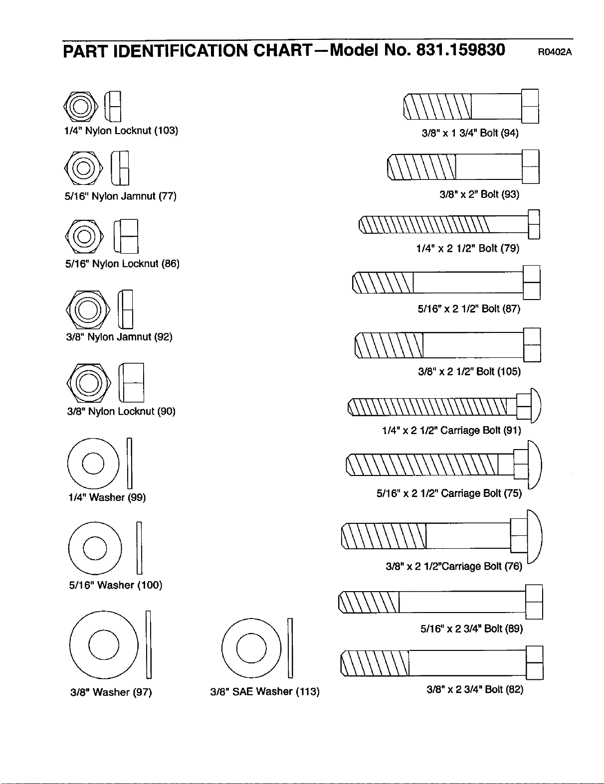
PART IDENTIFICATION CHART--Model No. 831.159830 Ro402A
1/4" Nylon Locknut (103)
5/16" Nylon Jamnut (77)
5/16" Nylon Locknut (86)
3/8" Nylon Jamnut (92)
3/8" Nylon Locknut (90)
114"Washer (99)
5116" Washer (100)
3/8" Washer (97)
3/8" SAE Washer (113)
3/8" x 1 314" Bolt (94)
318" x 2" Bolt (93)
_\\\\\\\\\\\\\\\\\\\\
1/4" x 2 1/2" Bolt (79)
_,\\\\\\l _
5/16" x 2 112" Bolt (87)
3/8" x 2 1/2" Bolt (105)
_\\\\\\_\\\\\\\\\\\\\\\_
1/4" x 2 1/2" Carriage Bolt (91)
_\\\\\\\\\\\\\\\\\ I
5/16" x 2 1/2" Carriage Bolt (75)
318"x 2 1/2"Carriage Bolt (
_\\\\\\1
5/16" x 2 3/4" Bolt (89)
3/8" x 2 314" Bolt (82)
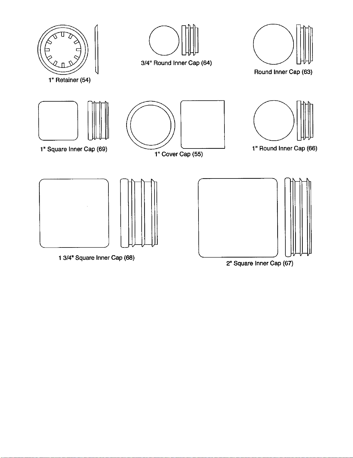
1" Retainer (54)
3/4" Round Inner Cap (64)
Round Inner Cap (63)
1" Square Inner Cap (69)
1" Cover Cap (55)
1" Round Inner Cap (66)
!
J
1 3/4" Square Inner Cap (68)
i
(-
2" Square Inner Cap (67)
_\\\\\\1 _]
5116"x 1 3/4" Bolt (96)
5116" x 1" Shoulder Bolt (84)
5116" x 3" Bolt (107)
_\\\\\\l [_
5116"x 2 3/4" Shoulder Bolt (108)
1" Tap Screw (80)
1/4" x 3/4" Bolt (98)
318"x 3" Bolt (88)
318"x 3 114" Bolt (104)
318"x 3 1/2" Bolt (111)
3/8" x 3 1/2" Carriage Bolt (95) [_
318"x 3 3/4" Bolt (101)
318"x 4" Bolt (78)
318" x 4" Carriage Bolt (112)
318"x 4 114" Bolt (85)
3/8" x 4 3/4" Bolt (102)
O
o
m
x
O3
SAVE THIS PART LIST/EXPLODED DRAWING FOR FUTURE REFERENCE
PART LIST-- Model No. 831.159830 Ro.o2A
Key No. Qty. Description Key No. Qty.
1 1 Butterfly Base 59 1
2 1 Center Base 60 2
3 1 Press Base 61 2
4 1 Butterfly Upright 62 4
5 1 Press Upright 63 2
6 1 Updght Support 64 4
7 1 Butterfly Top Frame 65 2
8 1 Center Top Frame 66 2
9 1 Press Top Frame 67 15
10 1 Butterfly Seat Frame 68 7
11 1 Butterfly Leg 69 1
12 1 Press Seat Frame 70 1
13 1 Leg Lever 71 1
14 1 Leg Press Lever 72 1
15 1 Adjustment Tube 73 1
16 1 Leg Press Plate 74 1
17 1 Press Frame 75 10
18 2 Press Arm 76 1
19 1 Right Butterfly Arm 77 3
20 1 Left Butterfly Arm 78 1
21 1 Curl Post 79 5
22 1 Cud Pad 80 2
23 2 Seat 81 2
24 1 Press Backrest 82 10
25 1 Butterfly Backrest 83 1
26 2 Right Weight Guide 84 2
27 2 Left Weight Guide 85 1
28 2 Small Support Plate 86 36
29 2 Large Support Plate 87 5
30 3 Seat Plate 88 1
31 1 Double =U'-Bracket 89 14
32 4 Pulley Plate 90 30
33 2 "U"-Bracket 91 3
34 4 =V-Pulley 92 16
35 25 3 1/2" Pulley 93 6
36 2 4 1/2" Pulley 94 6
37 4 Long Cable Trap 95 2
38 19 Cable Trap 96 3
39 2 Pulley Cover 97 18
40 1 Adjustment Pin 98 8
41 13 Weight 99 10
42 2 Top Weight 100 9
43 1 Long Weight Tube 101 7
44 1 Short Weight Tube 102 3
45 2 Weight Tube Bumper 103 5
46 4 Weight Bumper 104 4
47 1 Bottom Weight 105 2
48 1 Weight Plate 106 1
49 1 Cud Knob 107 4
50 2 Bumper 108 1
51 2 Pad Tube 109 4
52 4 Foam Pad 110 2
53 2 Large Foam Pad 111 1
54 4 1" Retainer 112 1
55 2 1" Cover Cap 113 4
56 1 Ab Strap # 1
57 1 Chain # 1
58 3 Cable Clip
Description
LetBar
PlasticBushing
LargeBushing
Handgrip
RoundInnerCap
3/4" RoundinnerCap
ButterflyArm Bushing
1"RoundInnerCap
2"SquareInner Cap
1 3/4"Square InnerCap
1"Squareinner Cap
Rear Cable
LowCable
PressCable
ButterflyCable
Ab Cable
5/16"x 2 112"Cardage Bolt
3/8"x 2 112"CarriageBolt
5/16" NylonJamnut
3/8"x 4" Bolt
1/4"x 2 1/2" Bolt
1"TapScrew
Weight Pin
3/8" x 2 3/4" Bolt
Nylon Strap
5/16"x 1" Shoulder Bolt
3/8"x 4 114"Bolt
5/16" Nylon Locknut
5/16" x 2 1/2"Bolt
3/8"x 3" Bolt
5/16" x 2 3/4" Bolt
3/8" Nylon Locknut
1/4"x 2 1/2" Carriage Bolt
3/8" Nylon Jamnut
3/8" x 2" Bolt
3/8" x 1 314"Bolt
3/8" x 3 1/2" Cerriege Bolt
5/16"x 1 3/4" Bolt
3/8" Washer
1/4"x 3/4" Bolt
1/4"Washer
3/16" Washer
3/8" x 3 3/4" Bolt
3/8" x 4 3/4"Bolt
114"Nylon Locknut
3/8"x 3 1/4" Bolt
3/8" x 2 lt2" Bolt
3/8"x 8" Bolt
5/16 x 3"Bolt
5/16"x 2 3/4" ShoulderBolt
MediumSupportPlate
Pro Pulley
3/8"x 3 112"Bolt
3/8" x 4"CarriageBolt
3/8" SAEWasher
User's Manual
Exercise Guide
Note: =#"indicatesa non-illustratedpart. Specificationsare subjectto change withoutnotice.
38 112
86 75 76
16
:23
(:3
4_
C:)
SEARS
Model No. 831.189830
QUESTIONS?
if you find that:
• you need help assembling or
operating the WELDER*PRO
POWER STACK weight system
• a part Is missing
• or you need to schedule repair
service
call our toll-free HELPLINE
1-800-736-6879
Monday-Saturday, 7 am-7 pm
Central Time (excluding holidays)
REPLACEMENT
PARTS
If parts become worn and need to
be replaced, call the following toll-
free number
1-800-FON-PART
(1-800-366-7278)
The model number and serial numberof yourWELDERe PRO
POWER STACK weightsystem are listedon a decal attached to
the frame. See the front cover of this manualto find the location
of the decal.
All replacement parts are available for immediatepurchase or
specialorder when you visityour nearest SEARS Service Center.
To requestservice or to order parts bytelephone, call the toll-free
numbers listedat the left.
When requestinghelp or service,or orderingparts,please be
prepared to providethefollowinginformation:
• The MODEL NUMBER ofthe product (831.159830)
• The NAME of the product(WELDERe PRO POWER STACK
weightsystem)
• The KEY NUMBER and DESCRIPTION of the PART (see the
PARTLIST/EXPLODED DRAWING in the centerof thismanual).
SEARS, ROEBUCK AND CO., HOFFMAN ESTATES, IL 60179
l FULL 90 DAY WARRANTY J
For 90 days from the date of purchase, iffailure occursdue to defectin material or workmanshipin this
SEARS WEIGHT SYSTEM EXERCISER, contactthe nearest SEARS Service Centerthroughoutthe
United States and SEARS will repairor replacethe WEIGHT SYSTEM EXERCISER, free of charge.
This warrantydoes not applywhen the WEIGHT SYSTEM EXERCISER is usedcommerciallyor for
rental purposes.
This warranty givesyou specificlegal rights,and you may also have other rightswhichvaryfrom state
to state.
SEARS, ROEBUCK AND CO., DEPT. 817WA, HOFFMAN ESTATES, IL 60179
Part No. 183713 R0402A Pdntedin Canada © 2002 Seam, Roebuck and Co.