Loading ...
Loading ...
Wait at least three (3) hours after
receivingthisbuilt-inovenbeforeswitchingthepoweron
to preventpossibledamageto thebuilt-inovencontrol
at poweron.
3. Adjusting Oven Height
Oven height can be adjusted when needed to fit into an
existing cabinet cutout opening. To adjust oven height:
1. Lay the oven on its back.
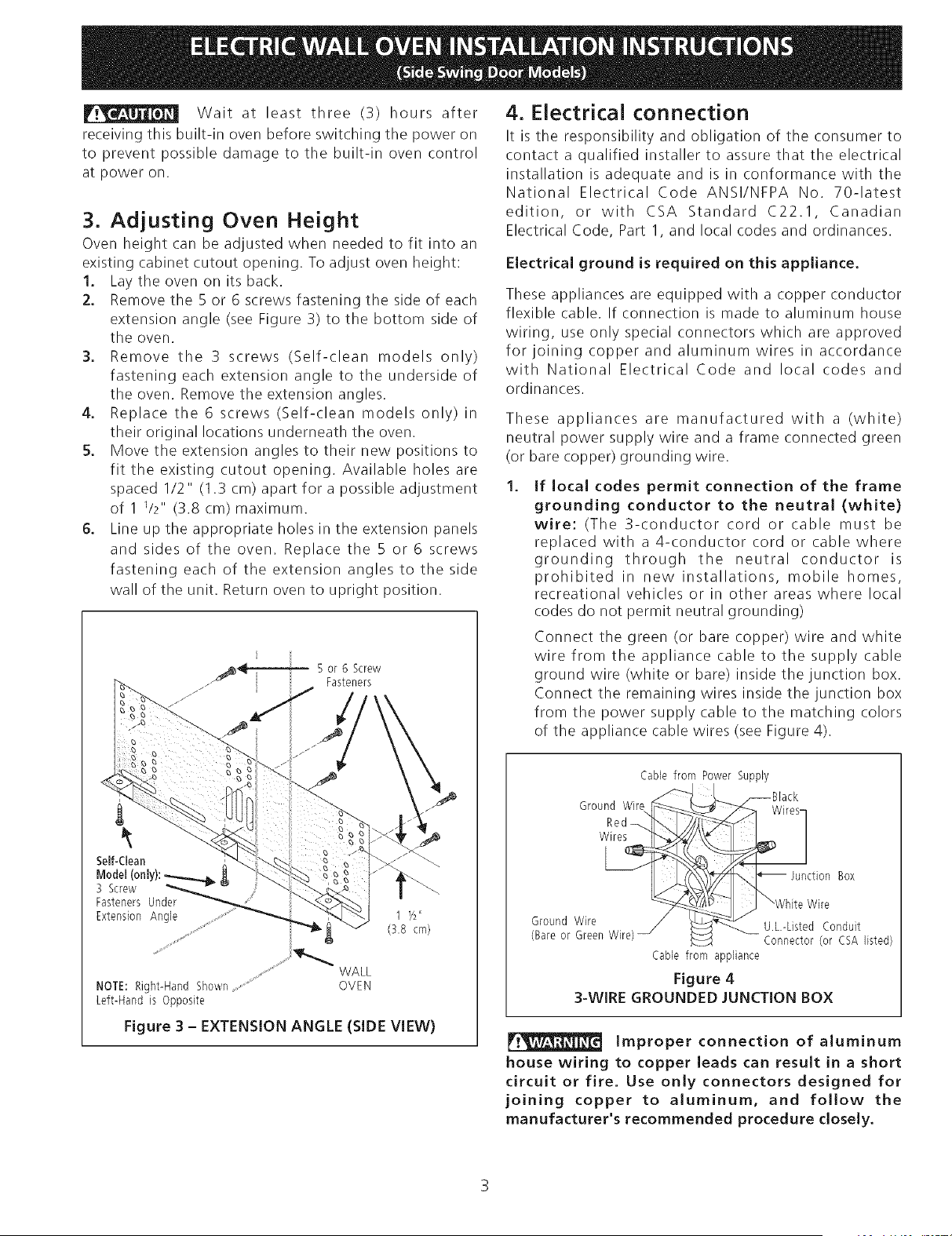
2. Remove the 5 or 6 screws fastening the side of each
extension angle (see Figure 3) to the bottom side of
the oven.
3. Remove the 3 screws (Self-clean models only)
fastening each extension angle to the underside of
the oven. Remove the extension angles.
4. Replace the 6 screws (Self-clean models only) in
their original locations underneath the oven.
5. Move the extension angles to their new positions to
fit the existing cutout opening. Available holes are
spaced 1/2" (I .3 cm) apart for a possible adjustment
of 1 1/2" (3.8 cm) maximum.
6. Line up the appropriate holes in the extension panels
and sides of the oven. Replace the 5 or 6 screws
fastening each of the extension angles to the side
wall of the unit. Return oven to upright position.
5 or 6 Screw
Fasteners
Self-Clean
Model (0nly): _
3 Screw
Fasteners Under
Extension Angle
....... WALL
NOTE: Right-Hand Shown .....................................OVEN
Left-Hand is Opposite
Figure 3 - EXTENSION ANGLE (SIDE VIEW)
4. Electrical connection
It is the responsibility and obligation of the consumer to
contact a qualified installer to assure that the electrical
installation is adequate and is in conformance with the
National Electrical Code ANSI/NFPA No. 70-latest
edition, or with CSA Standard C22.1, Canadian
Electrical Code, Part I, and local codes and ordinances.
Electrical ground is required on this appliance.
These appliances are equipped with a copper conductor
flexible cable. If connection is made to aluminum house
wiring, use only special connectors which are approved
for joining copper and aluminum wires in accordance
with National Electrical Code and local codes and
ordinances.
These appliances are manufactured with a (white)
neutral power supply wire and a frame connected green
(or bare copper) grounding wire.
If local codes permit connection of the frame
grounding conductor to the neutral (white)
wire: (The 3-conductor cord or cable must be
replaced with a 4-conductor cord or cable where
grounding through the neutral conductor is
prohibited in new installations, mobile homes,
recreational vehicles or in other areas where local
codes do not permit neutral grounding)
Connect the green (or bare copper) wire and white
wire from the appliance cable to the supply cable
ground wire (white or bare) inside the junction box.
Connect the remaining wires inside the junction box
from the power supply cable to the matching colors
of the appliance cable wires (see Figure 4).
Cable from Power Supply
Ground Wire
Red
Box
Wire
Ground Wire U.L.-Listed Conduit
(Bare or Green Wire Connector (or CSA listed)
Cable from appliance
Figure 4
3-WIRE GROUNDED JUNCTION BOX
Improper connection of aluminum
house wiring to copper leads can result in a short
circuit or fire. Use onJy connectors designed for
joining copper to aluminum, and folJow the
manufacturer's recommended procedure doseJy.
Loading ...
Loading ...
Loading ...