Loading ...
Loading ...
Loading ...
15
NOTE: AC power should be turned off at this stage.
• After selecting the proper location for your alarm, and wiring the AC QUICK CONNECT harness as described in
the WIRING INSTRUCTIONS, attach the mounting bracket to the electrical box. To ensure aesthetic alignment of
the alarm with the hallway, or wall, the “A” line on the mounting bracket must be parallel with the hallway when
ceiling mounted, or horizontal when wall mounted.
• Pull the AC QUICK CONNECTOR through the center hole in the mounting bracket and secure the bracket, making
sure that the mounting screws are positioned in the small ends of the keyholes before tightening the screws.
• Plug the AC QUICK CONNECTOR into the wiring harness attached to the unit, making sure that the locks on the
connector snap into place. Then push the excess wire back into the electrical box through the hole in the center
of the mounting bracket.
• Install the alarm fully on the mounting bracket by rotating the alarm in a clockwise direction. NOTE: The alarm
will mount to the bracket in 4 positions (every 90 degrees). NOTE: Installing the alarm on the mounting
bracket will automatically activate the battery backup.
Additional
Alarm
REDBLACK
WHITE
Additional
Alarm
REDBLACK
WHITE
FUSE OR CIRCUIT BREAKER
REDBLACK
WHITE
Kidde Relay Module
SM120X, CO120X
or both
Optional
Accessory
First
Alarm
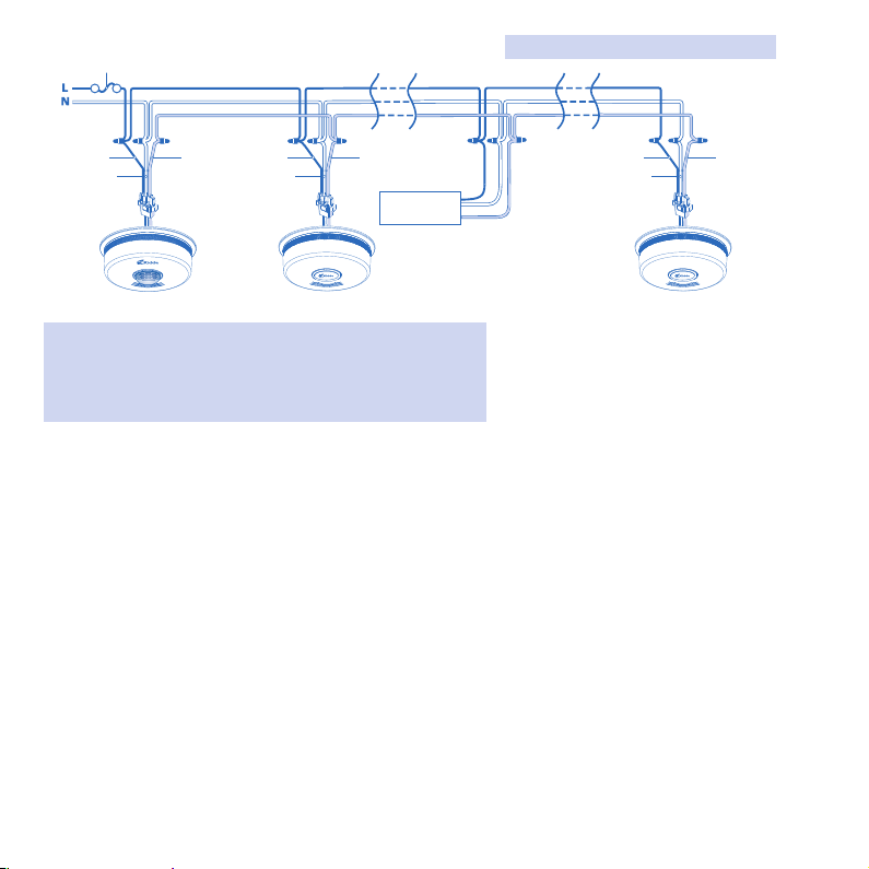
Figure 9-A, Interconnect Wiring Diagram
Wires on alarm harness: Connected to:
Black: Hot side of AC line
White: Neutral side of AC line
Red: Interconnect lines (red wires) of other
units in the multiple station set-up
Loading ...
Loading ...
Loading ...