©@HTEHTg
SAFETY
Anti-Tip Device ............................................ 2, 3, 27, 36
Important Safety Instructions ................................ 2-5
q_STALLATR@_ ......................................26-40
Air Adjustment ........................................................... 35
Dimensions and Clearances .................................... 26
Electrical Connections ........................................ 31, 32
Gas Pipe and Electric Outlet Locations .................. 29
LP Conversion ............................ ;............................. 37-40
Installing the Anti-Tip Device ................................... 36
USE A_D ©ARE
Baking .................................................................. 12, 13
BroilingtBroiling Guide ...................................... 17, 18
Care and Cleaning .............................................. 19-25
Cooktop Comparison .................................................. 7
Clock and Timer ........................................................... 9
Features of Your Range ............................................. 6
RoastingtRoasting Guide ................................... 15, 16
Surface Cooking ..................................................... 7-9
Using Your Oven ................................................ 10, 11
IERVI©IE
Problem Solver ................................................... 41, 42
Thermostat Adjustment ........................................... .14
MODELS 61011 71151 71758
61018 71! 58 75251
61111 71651 75258
61118 71858 72751
61251 75151 72758
61258 75158 72755
71051 71751
@
K®nmop@
:_::::!::)!i;_:if)]¸_:i]i:,:
164D2764P049
SR4219 1
WARNING: tf the information in this
manual is not followed exactly, a fire
or explosion may result causing prop-
erty damage, personal injury or death.
Do not store or use gasoline or other
flammable vapors and liquids in the
vicinity of this or any other appliance.
WHAT TO DO IF YOU SMELL GAS
oDo not try to light any appliance.
oDo not touch any electrical switch;
do not use any phone in your
building.
oImmediately call your gas supplier
from a neighbor's phone. Follow the
gas supplier's instructions.
oIf you cannot reach your gas
supplier, call the fire department.
Installation and service must be
performed by a qualified installer,
service agency or the gas supplier.
DEVICES PACKED
WITH RANGE
o SEE INSTALLATION
INSTRUCTIONS
:::::::::::::::::::::::::::
:::_:::::aCCdrdin:gt6:15cai:;
propel
ment:;and: e_i :sti
::::::::fOr
::::::::::::Electii:ca
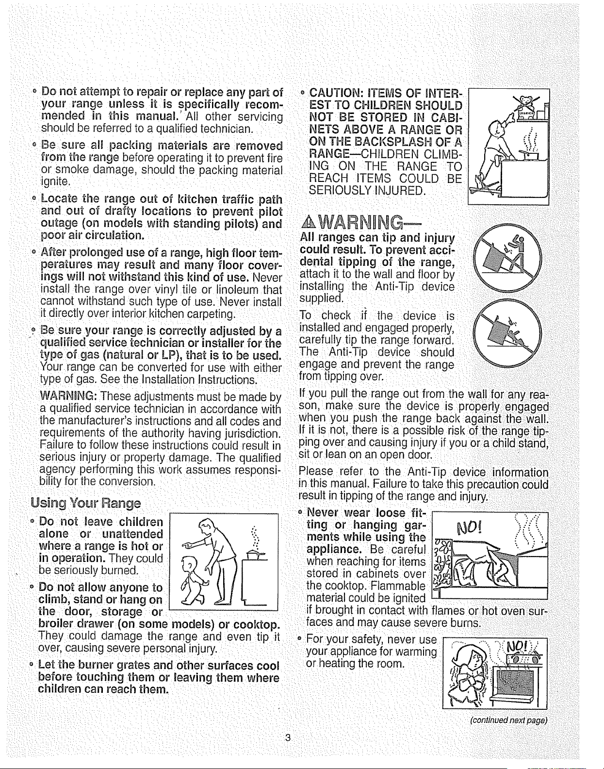
o Do not attempt to repair or replace any part of o
your range unless it is specifically recom,
mended in this manual.' All other servicing
shoufd be referred to a qualified technician.
o Be sure all packing materiams are removed
from the range before operating it to prevent fire
or smoke damage, should the packing material
ignite.
o Locate the range out of kitchen traffic path
and out of drafty locations to prevent pilot
outage (on models with standing pilots) and
poo_' air circulation.
o After prolonged use of a range, high floor tem-
peratures may resutt and many floor cover-
ings will not withstand this kind of use. Never
install the range over vinyl tile or linoleum that
cannot withstand such type of use. Never install
it directly over interior kitchen carpeting.
._ Be sure your range is correctly adjusted by a
qualified service technician or installer for the
CAUTION: JTEIVtS OF INTER-
ESTTO CHILDREN SHOULD
NOT BE STORED IN CABF
NETS ABOVE A RANGE OR
ON THE BACKSPLASH OF A
RANGE--CHILDREN CLIMB-
ING ON THE RANGE TO
REACH ITEMS COULD BE
SERIOUSLY INJURED.
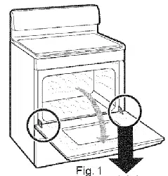
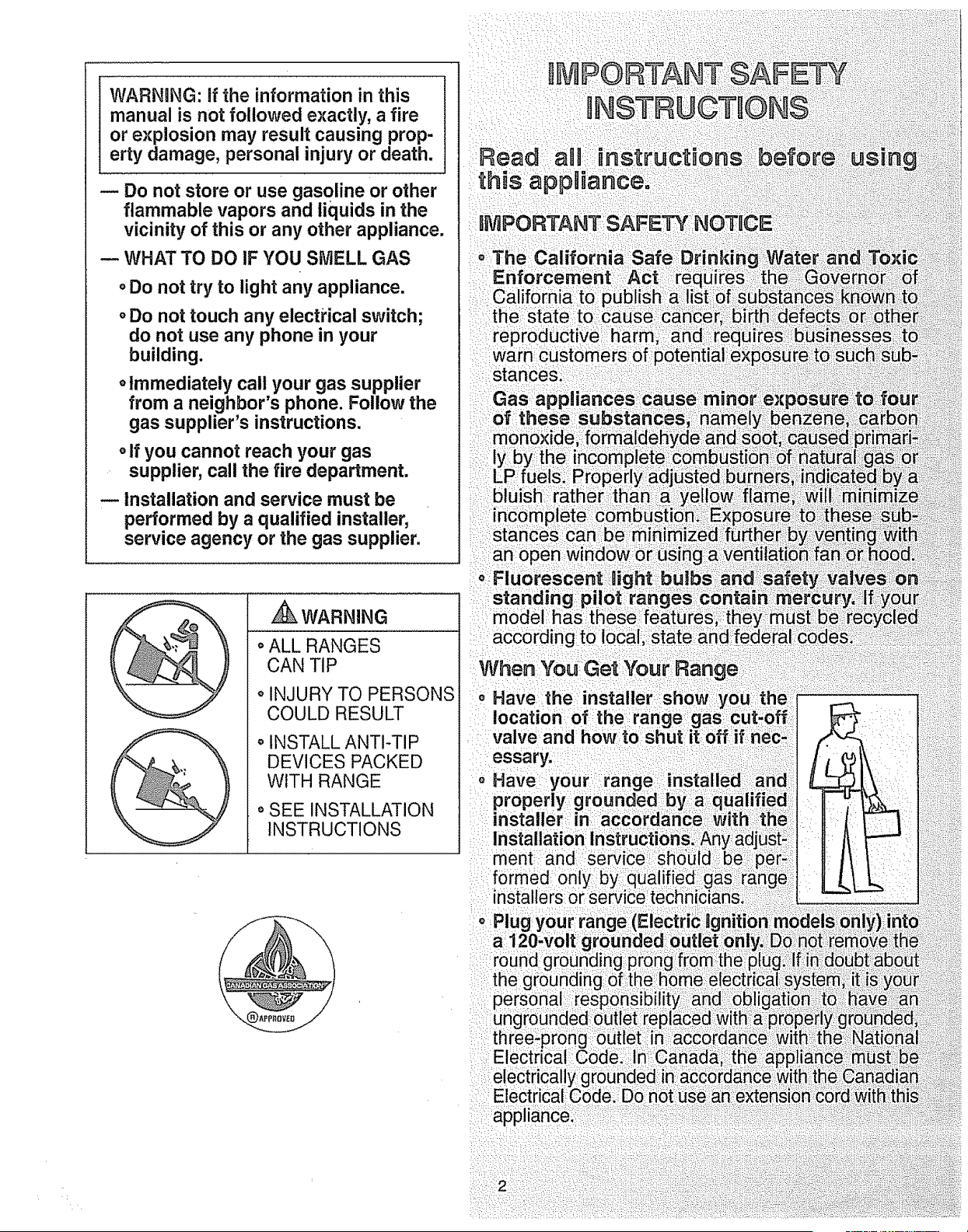
AWAIRINING
All ranges can tip and injury
could result. To prevent acci-
dental tipping of the range,
attach it to the wall and floor by
installing the Anti-Tip device
supplied.
To check if the device is
installed and engaged properly,
carefully tip the range forward.
type of:gas (natural or LP), that is tobe used. The Anti'Tip device
_.'h : engage and prevent the rang_
Your range can be converted for use with _tt_er _ . ....
type of gas. See the Installation Instructions. from bpplng over.
WARNaNG: These adjustments must be made by lfyou pu the range out from the wa
a qualified sewice technician in accordance with
the manufacturer's instructions and all codes and
requirements of the authority llaving jurisdiction.
Failure to follow these instructions could result in
serious injury or property damage. The qualified
agency performing this work assumes responsi-
bility for the conversion.
son, make sure the device is
when you push the range bacl_ r0perp
If it is not, there is a possible risk:,
ping over and causing injury if you orac
sit or lean on an open door.
Using You_"Range
o Do :not leave children
alone or unattended
where a range is hot or
in operation. They could
be seriously burned.
o Do not allow anyone to
climb, stand or hang on
the door, storage or
J
broiler drawer (on some models) or cooktop.
They could damage the range and even tip it
over, causing severe personal injury.
oLet the burner grates and othersurfaces cooJ .......... the room.
before touching them or leaving them where
children can reach them.
Please refer to the Anti-Tip device .............
in this manual. Failure to take this precaution coUld: :: i_:: :i
result in tipping of the range and injuryl
,,:Never wear loose fit- :
ring or hanging gar- Ik_O!
ments while using the
appliance. :Be carefu
when reaching for items
stored in cabinets over
the cooktop. Flammable
material could be ignited
if brought in contact with flame_
faces and may cause severe burr
o :For your safety, never use
your appliance for warming
(continued next
SAEEP¢::INSTR!
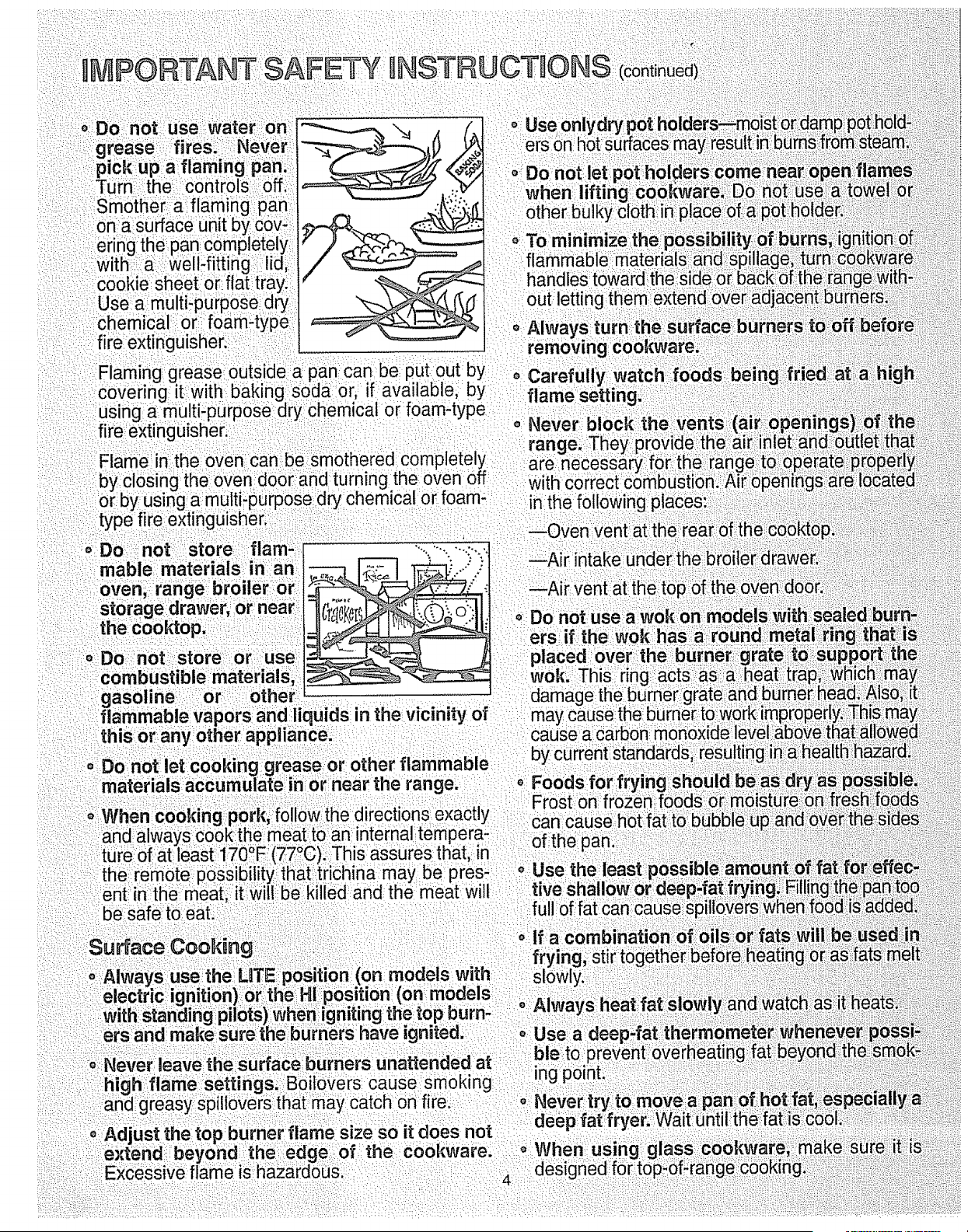
laN mable: _at eri
;, f: av&ilaBie;:: :: : e=i ,
ir,,icai:or foam:type::::::: ::
::::: :v:: ¸ ;_;: i¸
.................... d,ln
:va _OrSand ik Uids in Use:::
near :::
n::inter nal:teN :
ic!::i
:and::the
: :::_: Ing poln
o Use proper pan size. Avoid pans that are unsta-
ble or easily tipped. Select cookware having flat
bottoms large enough toproperly contain food o Place the oven shelves in the desired position
and avoid boilovers and spi!lovers and large : while the oven is cool.
enough to cover burner grates. Th s will both save:° Pulling out the shelf to the shelf-stop is a
cleaning time and prevent hazardous accumula- convenience in lifting heavy foods. Utis also a
tions of food, since heavy spattering or spillovers precaution against burns from touching hot
left on tl_e range can ignite. Use pans with han,
dies that can be easily grasped and will remain
cool.
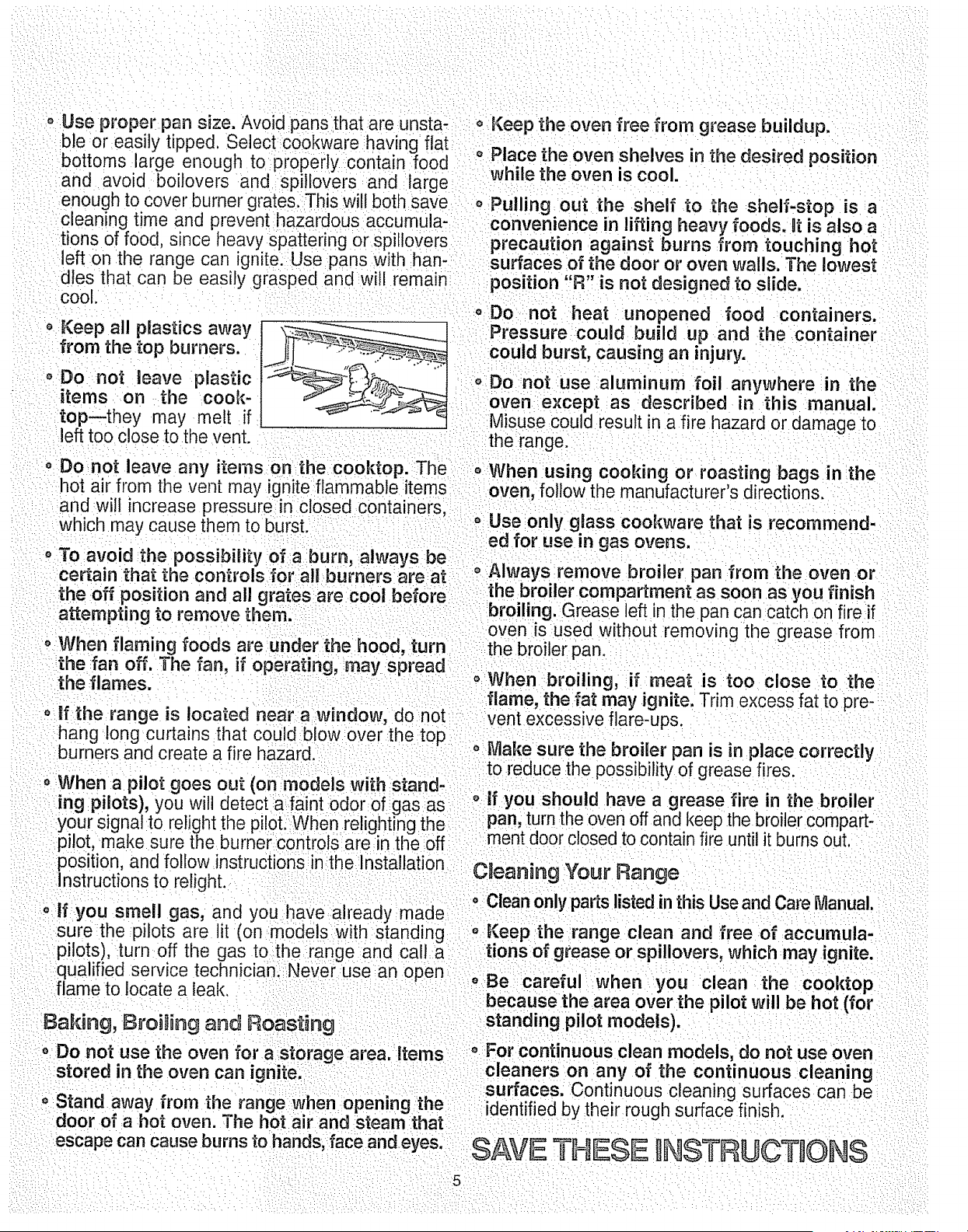
,,Keep all plastics away
from the top burners.
,,Do not leave plastic
items on the cook-
topwthey may melt if
left too close to the vent.
°Keep the oven free from grease buildup.
o Do:not heat unopened food containers.
Pressure could build up and the container
could burst, causing an injury.
_ Do not use aluminum foil anywhere in the
oven except as described in this manual.
Misuse could result in a fire hazard or damage to
the range.
o Donot leave any items onthe cooktop. The :::,,When using cooking or roasting bags in the
hot air from tile vent rnay ignite flammable items
and :will increase pressure in closed containers,
which may cause them to burst.
,, To avoid the possibility of a:burn, always be
certain that the controls :for all burners areiat
the off position and all grates are cool before
attempting to remove them.
OWhen flaming foods are under the hood, turn
oven, follow the manufacturer's directions.
o Useonly glass cookware that is recommend-
ed for use in gas ovens.
:Always remove broiler pan from the oven or
the broiler compartment as soon as you finish
broiling, Grease left in the pan can catch on fire if
oven rs used without removing the grease from
the broiler pan.
the fan off. The
fan,
if
operating,
ma.s,re_:::voad _,When broiling, if meat is too close to the
the flames.
o |fthe range is located near a window, do not
hang long curtains that could b!ow over-the:top
:burners a_ndc_:eatea fire hazard. ::: :
olWhen a pilot goes out (on ::models with :stand'
ing pilots), you will detect a faint :odor of ::gasas
your sJgnal:to relight the pilot; When relight ngthe
pilot, make sure the burner controls are in the off
position, and follow instructions in the Installation
Instructions to relight.
flame, the fat may ignite. Trim excess fat to pre-
vent excessive flare-ups.
Make sure the broiler pan is in place correctly
_ If you smell gas, and you have already made
sure the pilots are lit (on rnodels With standing
pilots),: :turn off the gas to the range and ca la
qualified service technician} Never use an open
flame to locate a leak.
Baking, BroiSing and Roasting
o Do not use the oven for astorage area. Items
stored in the oven can ignite. :i:
,,Stand away from the range when opening the
door of a hot oven. The hot air and steam that
escape can cause burns tohands, face and eyes. SAVE YHESE INSTRUCYDONS
to reduce :the possibility of grease fires.
if you should have a grease fire in the broiler
pan, turn the oven offand keep the broiler compart-
ment door closed to contain fire until it burns out,
Cleaning Your Range
oClean only parts listedin this Useand CareManual.
°Keep the range clean and free of accumula-
itions of grease or spillovers, which may ignite.
oBe:careful:when you clean the cooktop
because the area over the pilot will be hot (for
standing pilot models).
For continuous clean models, do not use oven
cleaners on any of the continuous cleaning
surfaces. Continuous cleaning surfaces can be
identified by their rough surface finish.
surfaces of the door or oven walls. The lowest
position "R" is not designed to slide.
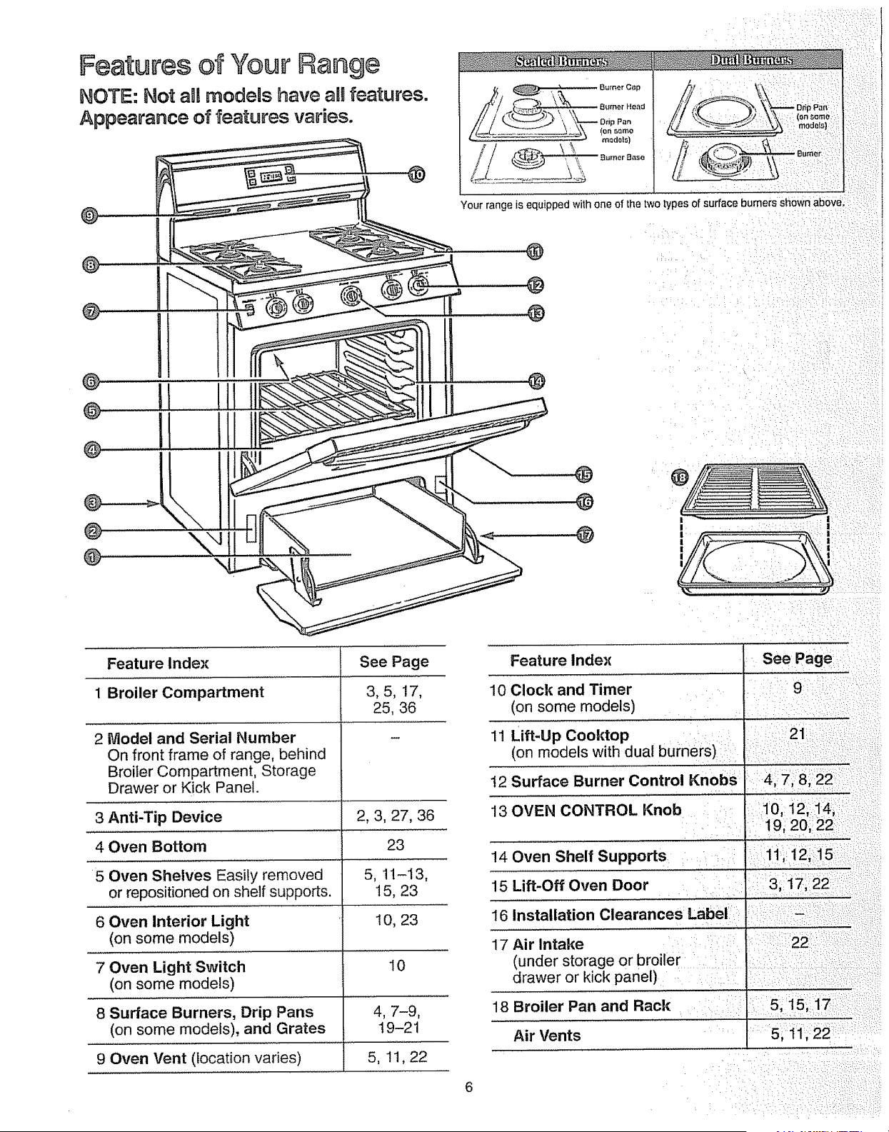
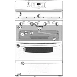
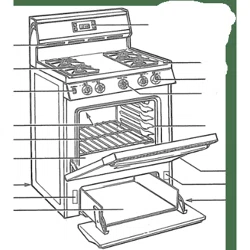
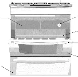
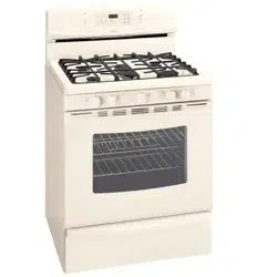
Features Your Range
NOTE: Not a01modeUs have aH features.
Appearance of features varies.
@
Burner Cap
Your range is equipped with one of the two types of surface burners shown above_
t
@
@
®
@
@
@
Feature Index See Page
1 Broiler Compartment 3, 5, 17,
25, 36
2 Model and Serial Number
On front frame of range, behind
Broiler Compartment, Storage
Drawer or Kick Panel.
3 Anti-Tip Device 2, 3, 27, 36
4 Oven Bottom 23
5 Oven Shelves Easily removed 5, 11-13,
or repositioned on shelf supports. 15, 23
!0, 23
6 Oven Interior Light
(on some models)
7 Oven Light Switch 10
(on some models)
8 Surface Burners, Drip Pans 4, 7-9,
(on some models), and Grates 19-21
9 Oven Vent (location varies) 5, 11,22
6
Feature Index
10 Clock and Timer
(on some models)
11 Lift-Up Cooktop
(on models with dual burners)
See Page
9
21
12 Surface Burner Control Knobs
13 OVEN CONTROL Knob
14 Oven Shelf Supports
15 Lift-Off Oven Door
16 Installation Clearances Label
17 Air Intake
(under storage or broiler
drawer or kick panel)
18 Broiler Pan and Rack
Air Vents
4, 7,8;22
10, 12;14,
19, 201: 22:
11, !2,:!5
3, 17,22::i:
22: •
5, 15;17
5;!1,22 ....
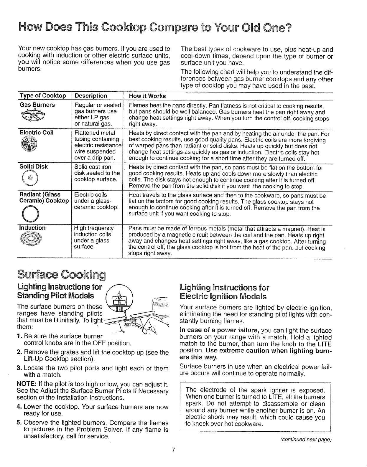
How Does Thns Coo op Compare to Your One?
Your new cooktop has gas burners. If you are used to
cooking with induction or other electric surface units,
you will notice some differences when you use gas
burners.
The best types of cookware to use, plus heat-up and
cool-down times, depend upon the type of burner or
surface unit you have.
The following chart will help you to understand the dif-
ferences between gas burner cooktops and any other
type of cooktop you may have used in the past.
Type of Cooktop Description How it Works
Gas Burners
Electric Coil
@
Solid Disk
G
Radiant (Glass
Ceramic) Cooktop
Regular or sealed
gas burners use
either LP gas
or natural gas.
Flattened metal
tubing containing
electric resistance
wire suspended
over a drip pan.
Solid cast iron
disk sealed to the
cooktop surface.
Electric coils
under a glass-
Flames heat the pans directly. Pan flatness is not critical to cooking results,
but pans should be well balanced. Gas burners heat the pan right away and
change heat settings right away. When you turn the control off, cooking stops
right away.
Heats by direct contact with the pan and by heating the air under the pan. For
best cooking results, use good quality pans. Electric coils are more forgiving
of warped pans than radiant or solid disks. Heats up quickly but does not
change heat settings as quickly as gas or induction. Electric coils stay hot
enough to continue cooking for a stlort time after they are turned off,
Heats by direct contact with the pan, so pans must be flat on the bottom for
good cooking results. Heats up and cools down more slowly than electric
coils. The disk stays hot enough to continue cooking after it is turned off,
Remove the pan from the solid disk if you want the cooking to stop.
Heat travels to the glass surface and then to the cookware, so pans must be
flat on the bottom for good cooking results. The glass cooktop stays hot
O
Induction
,,\_ _t I tJJ_,,.,_,
ceramic cooktop.
High frequency
induction coils
under a glass
surface.
enough to continue cootdng after it is turned off. Remove the pan from the
surface unit if you want cooking to stop,
Pans must be made of ferrous metals (metal that attracts a magnet), Heat is
produced by a magnetic circuit between the coil and the pan. Heats up right
away and changes heat settings riglqt away, like a gas cooktop. After turning
the control offl the glass cooktop is hot from the heat of the pan, but cooking
stops right away.
Su#ace Cooking
Lighting instructions for/-"
Standing Pilot ModeRs
The surface burners on these _, ir-_
ranges have standing pilots _
that must be lit initially. To light
them: " _'-_
1. Be sure the surface burner
control knobs are in the OFF position.
2. Remove the grates and lift the cooktop up (see the
Lift-Up Cooktop section).
3. Locate the two pilot ports and light each of them
with a match.
NOTE: if the pilot is too high or low, you can adjust it.
See the Adjust the Surface Burner Pilots if Necessary
section of the Installation Instructions.
4. Lower the cooktop. Your surface burners are now
ready for use.
5. Observe the lighted burners. Compare the flames
to pictures in the Problem Solver. If any flame is
unsatisfactory', call for service.
Lighting gnstructions for
EUectric Dgnition 1odens
Your surface burners are lighted by electric ignition,
eliminating the need for standing pilot lights with con-
stantly burning flames.
In case of a power failure, you can light the surface
burners on your range with a match. Hold a lighted
match to the burner, then turn the knob to the LITE
position. Use extreme caution when lighting burn-
ers this way.
Surface burners in use when an electrical power fail-
ure occurs will continue to operate normally.
The electrode of the spark igniter is exposed.
When one burner is turned to LITE, all the burners
spark. Do not attempt to disassemble or clean
around any burner while another burner is on. An
electric shock may result, which could cause you
to knock over hot cookware.
(continued next page)
Sulfate Ooo_i_g (continued)
Surface Burner Controls
The knobs that turn the surface burners on and off are
marked as to which burners they control.
The two knobs on the left control the left front and left
rear burners. The two knobs on the right control the
right front and right rear burners.
On ranges with sealed burners:
oThe smaller burner (right rear position) will give
the best simmer results. It offers precise cook-
ing performance for delicate foods, such as
sauces or foods which need to cook over low
heat for a long time. it can be turned down to a
very tow simmer setting.
° The right front burner is higher powered than the
others and will bring liquids to a boil quicker
(natural gas installations only).
Before Lighting a Burner
o If drip pans are supplied with your range, they should
be used at all times.
0 Make sure al! grates on the range are in place before
using a burner.
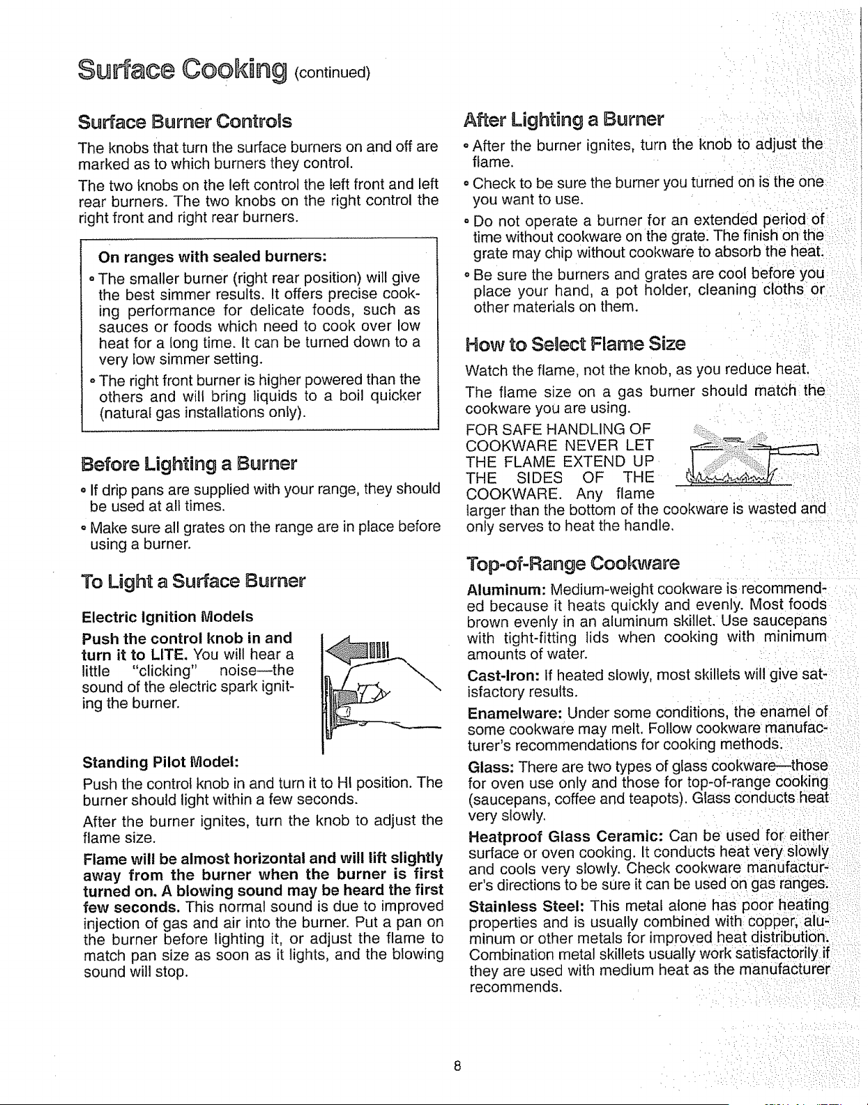
To Light a Surface Burner
Electric Ignition Models
Push the control knob in and
turn it to LITE. You wilt hear a
little "clicking" noise--the
sound of the electric spark ignit-
ing the burner.
Standing Pilot Model:
Push the control knob in and turn it to HI position. The
burner should light within a few seconds.
After the burner ignites, turn the knob to adjust the
flame size.
Flame will be almost horizontal and will lift slightly
away from the burner when the burner is first
turned on. A blowing sound may be heard the first
few seconds. This normal sound is due to improved
injection of gas and air into the burner. Put a pan on
the burner before lighting it, or adjust the flame to
match pan size as soon as it lights, and the blowing
sound will stop.
After Lighting a Burner
oAfter the burner ignites, turn the knob to adjust the
flame.
,, Check to be sure the burner you turned on is the one
you want to use.
o Do not operate a burner for an extended periodof
time without cookware on the grate: The finish on the
grate may chip without cookware to absorb the heat.
o Be sure the burners and grates are cool before you
place your hand, a pot holder, cleaning cloths or
other materials on them.
How to SeUectF ame Snze
Watch the flame, not the knob, as you reduce heat.
The flame size on a gas burner should match the
cookware you are using.
FOR SAFE HANDLING OF
COOKWARE NEVER LET
THE FLAME EXTEND UP
THE SIDES OF THE
COOKWARE. Any flame
larger than the bottom of the cookware is wasted and
only serves to heat the handle,
Top-of-Range Cookware
Aluminum: Medium-weight cookware is recommend.
ed because it heats quickly and evenly. Most foods
brown evenly in an aluminum skillet. Use saucepans
with tight-fitting lids when cooking with minimum
amounts of water.
Cast-Iron: If heated slowly, most skillets will give sat-
isfactory results.
Enamelware: Under some conditions, the enamel of
some cookwa_:e may melt. Follow cookware manufac-
turer's recommendations for cooking methods:
Glass: There are two types of glass cookware:--those
for oven use only and those for top-of-range cooking
(saucepans, coffee and teapots). Glass conducts:heat
very slowly,
Heatproof Glass Ceramic: Can be used for either
surface or oven cooking. It conducts heat verysiowly
and cools very slowly. Check cookware manufactur,
er's directions to be sure it can be used on gas ranges,
Stainless Steel: This metal alone has poor heating
properties and is usually combined with copper_ alu.:i
minum or other metals for improved heat distribution.
Combination metal skillets usually work satisfactorily if
they are used with medium heat as the manufacturer
recommends.
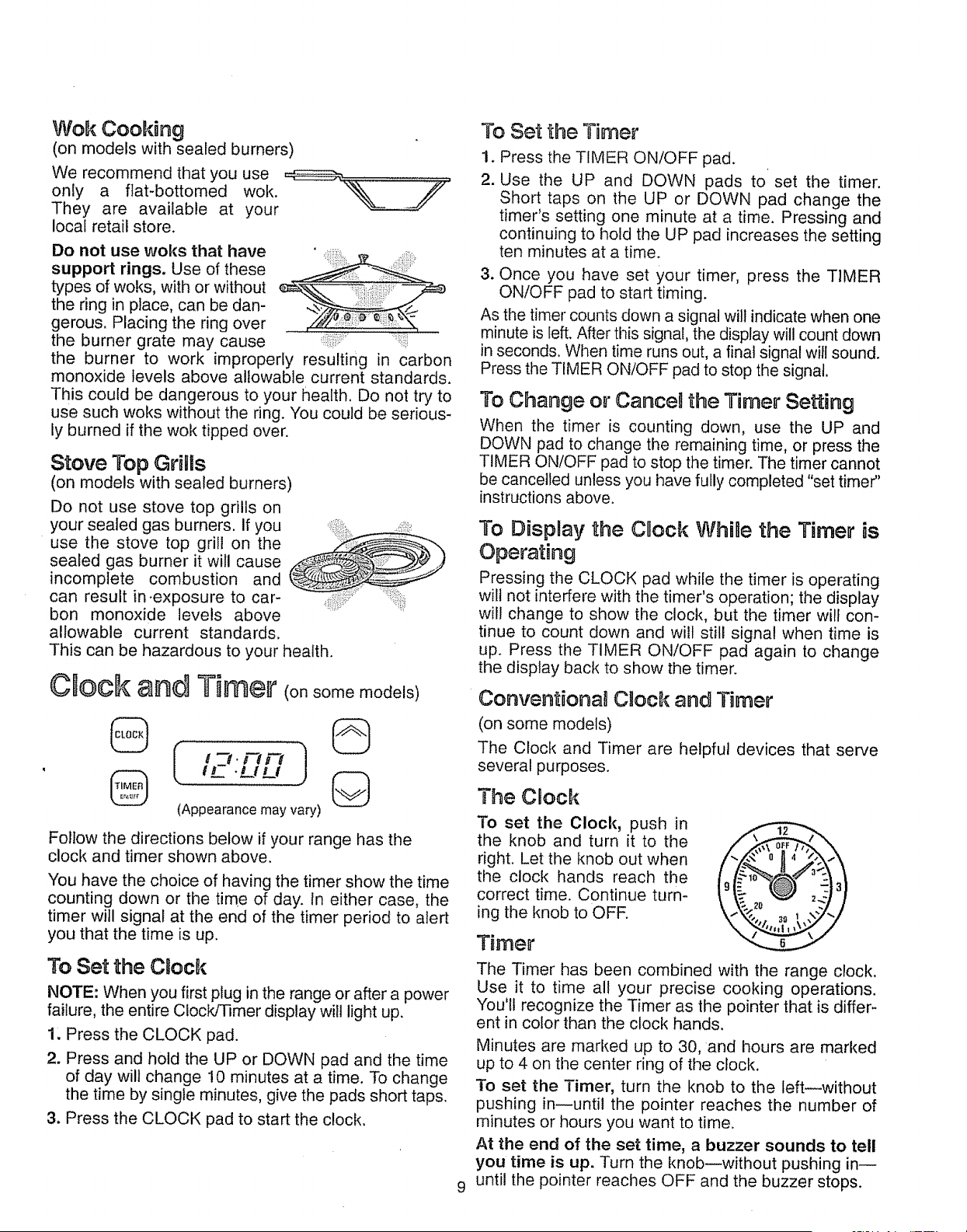
Wok Cooking
(on models with sealed burners)
We recommend that you use _\_____,
only a fiat-bottomed wok.
They are available at your
local retail store.
Do not use woks that have
support rings. Use of these
types of woks, with or without
the ring in place, can be dan-
gerous. Placing the ring over
the burner grate may cause
=_:i!ii
the burner to work improperly resulting in carbon
monoxide levels above allowable current standards.
This could be dangerous to your health. Do not try to
use such woks without the ring. You could be serious-
ly burned if the wok tipped over.
Stove Top Grills
(on models with sealed burners)
Do not use stove top grills on
your sealed gas burners. If you
use the stove top grill on the
sealed gas burner it will cause
incomplete combustion and
can result in-exposure to car-
bon monoxide levels above
allowable current standards.
This can be hazardous to your health.
OBockand Tim÷r ioo
6 ©
(Appearance may vary)
Fo)low the directions below if your range has the
clock and timer shown above.
You have the choice of having the timer show the time
counting down or the time of day. In either case, the
timer witl signal at the end of the timer period to alert
you that the time is up.
To Set the Clock
NOTE: When you first plug in the range or after a power
failure, the entire Clocldlqmer display will light up.
1. Press the CLOCK pad.
2. Press and hold the UP or DOWN pad and the time
of day wilt change 10 minutes at a time. To change
the time by single minutes, give the pads short taps.
3. Press the CLOCK pad to start the clock.
To Set the Timer
1. Press the TIMER ON/OFF pad.
2. Use the UP and DOWN pads to' set the timer.
Short taps on the UP or DOWN pad change the
timer's setting one minute at a time. Pressing and
continuing to hold the UP pad increases the setting
ten minutes at a time.
3. Once you have set your timer, press the TIMER
ON/OFF pad to start timing.
As the timer counts down a signal will indicate when one
minute is left. After this signal, the display will count down
in seconds. When time runs out, a final signal will sound.
Press the TIMER ON/OFF pad to stop the signat.
To Change or Canceg the Timer Setting
When the timer is counting down, use the UP and
DOWN pad to change the remaining time, or press the
TIMER ON/OFF pad to stop the timer. The timer cannot
be cancelled unless you have fuIly completed "set time€'
instructions above.
To DispUay the CHock Whine the Timer is
Operating
Pressing the CLOCK pad while the timer is operating
will not interfere with the timer's operation; the display
will change to show the clock, but the timer will con-
tinue to count down and will still signal when time is
up. Press the TIMER ON/OFF pad again to change
the display back to show the timer.
Conventiona_ CJock and Timer
(on some models)
The Clock and Timer are helpful devices that serve
several purposes.
The COock
To set the Clock, push in
the knob and turn it to the
right. Let the knob out when
the clock hands reach the
correct time. Continue turin
ing the knob to OFF.
Timer
The Timer has been combined with the range clock.
Use it to time all your precise cooking operations.
You'll recognize the Timer as the pointer that is differ-
ent in color than the clock hands.
Minutes are marked up to 30, and hours are marked
up to 4 on the center ring of the clock.
To set the Timer, turn the knob to the left--without
pushing in--until the pointer reaches the number of
minutes or hours you want to time,
At the end of the set time, a buzzer sounds to tell
you time is up. Turn the knob--without pushing in--
until the pointer reaches OFF and the buzzer stops.
Using Your Oven
:,: i : ,::: : ,:i _,
Before Using Your Oven
Be sure you understand how to set the control proper-
ly. Practice removing and replacing the shelves while
the oven is cool. Read the information and tips on the
following pages. Keep this manual handy where you
can refer to it, especially during the first weeks of
using your new range.
Lighting instructions for
Standing Pilot ModeUs
Some models have standing oven pilots that must be
lit initially.
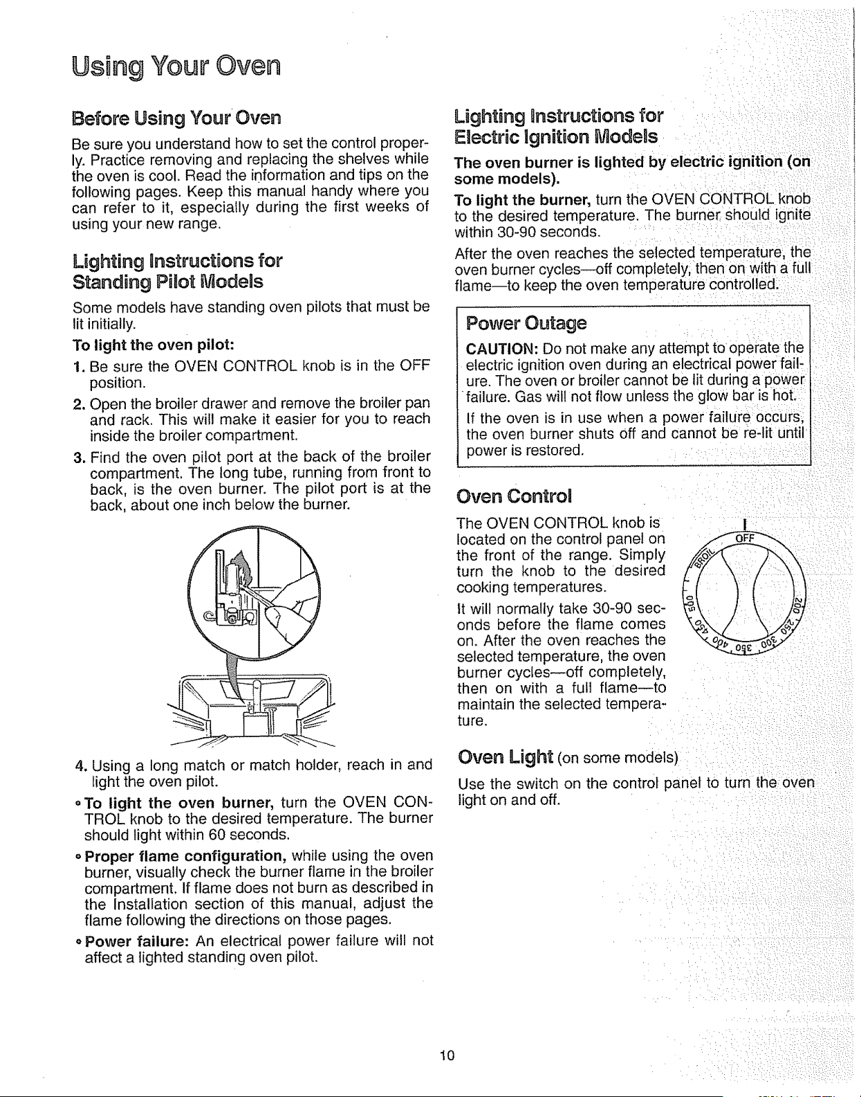
To light the oven pilot:
1. Be sure the OVEN CONTROL knob is in the OFF
position.
2. Open the broiler drawer and remove the broiler pan
and rack. This will make it easier for you to reach
inside the broiler compartment.
3. Find the oven pilot port at the back of the broiler
compartment. The long tube, running from front to
back, is the oven burner. The pilot port is at the
back, about one inch below the burner.
4, Using a long match or match holder, reach in and
light the oven pilot.
,,To light the oven burner, turn the OVEN CON-
TROL knob to the desired temperature. The burner
should light within 60 seconds.
o Proper flame configuration, while using the oven
burner, visually check the burner flame in the broiler
compartment. If flame does not burn as described in
the Installation section of this manual, adjust the
flame following the directions on those pages.
o Power failure: An electrical power failure will not
affect a lighted standing oven pilot.
Lighting Hnstructions for
Electric ignition Models
The oven burner is lighted by electric
some models). _ ::
To light the burner, turn the OVEN CONTROL !
to the desired temperature. The burner should ignite:_i:i:ii:ii,:iiiii
within 30-90 seconds. : .... i
After the oven reaches the seiected temperaiu:_ei:
oven burner cycles--off completelyl therl on with a full: i::i:i
flame--to keep the oven temperature €ont!olledi :i
Power Outage
CAUTION: Do not make any attempt tO operate the
electric ignition oven during an electrical powerfail_
ure. The oven or broiler cannot be lit during a p(
failure. Gas will not flow unless the glow bar is
If the oven is in use when a power failure ocCurSi
the oven burner shuts Off and cannot be re-lit Until
power is restored.
Oven ControU
The OVEN CONTROL knob is
located on the control panel on /.
the front of the range. Simply
turn the knob to the desired
cooking temperatures.
tt will normally take 30-90 sec-
onds before the flame comes k_
on. After the oven reaches the
selected temperature, the oven
burner cycles--off completely,
then on with a full flame--to
maintain the selected tempera-
ture.
•i•••!•:•:/•• • _:••i_•••/•
•
Oven Light (onsomemodels)
Use the switch on the control panel to turn the oven
light on and off.
!0
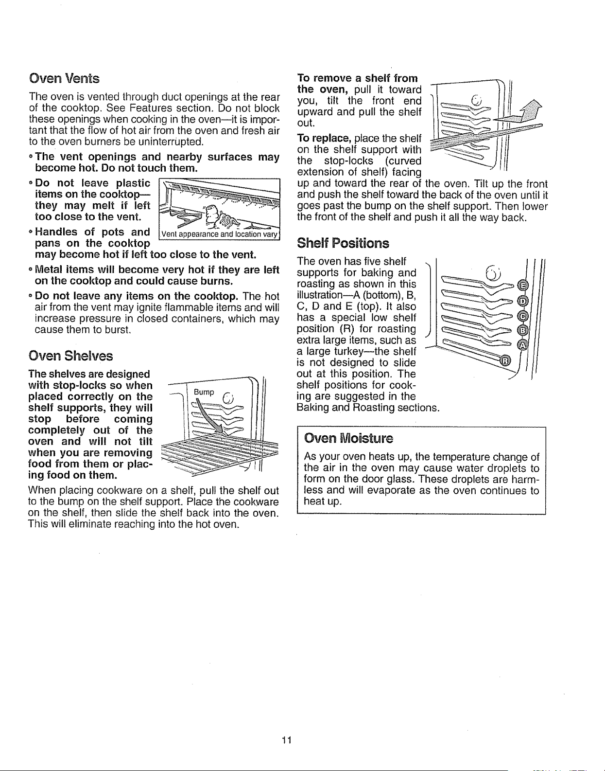
Oven Vents
The oven is vented through duct openings at the rear
of the cooktop. See Features section. Do not block
these openings when cooking in the oven--it is impor-
tant that the flow of hot air from the oven and fresh air
to the oven burners be uninterrupted.
°The vent openings and nearby surfaces may
become hot. Do not touch them.
o Do not leave plastic
items on the cooktop--
they may melt if left
too close to the vent.
°Handles of pots and
pans on the cooktop
t
may become hot if left too close to the vent.
o Metal items will become very hot if they are left
on the cooktop and could cause burns.
o Do not leave any items on the cooktop. The hot
air from the vent may ignite flammable items and will
increase pressure in closed containers, which may
cause them to burst.
Oven SheNes
The shelves are designed
with stop-locks so when
placed correctly on the
shelf supports, they will
stop before coming
completely out of the
oven and will not tilt
when you are removing
food from them or plac-
ing food on them.
When placing cookware on a shelf, pull the shelf out
to the bump on the shelf support. Place the cookware
on the shelf, then slide the shelf back into the oven,
This will eliminate reaching into the hot oven.
To remove a shelf from
the oven, pull it toward
you, tilt the front end
upward and pull the shelf
out.
To replace, place the shelf
on the shelf support with
the stop-locks (curved
extension of shelf) facing
up and toward the rear of the oven. Tilt up the front
and push the shelf toward the back of the oven until it
goes past the bump on the shelf support. Then lower
the front of the shelf and push it all the way back.
Shelf Positions
The oven has five shelf
supports for baking and
roasting as shown in this
illustration--A (bottom), B,
C, D and E (top). it also
has a special low shelf
position (R) for roasting
extra large items, such as
a large turkey--the shelf
is not designed to slide
out at this position. The
shelf positions for cook-
ing are suggested in the
Baking and Roasting sections.
/
Oven Moisture
As your oven heats up, the temperature change of
the air in the oven may cause water droplets to
form on the door glass. These droplets are harm-
less and will evaporate as the oven continues to
heat up.
11
Baking
Your oven temperature is controlled very accurately
using an oven control system. It is recommended that
you operate the oven for a number of weeks to
become familiar with you new oven's performance. If
you think an adjustment is necessary, see the Adjust
the Oven Thermostat section.
How to Set Your Range fer Baking
To avoid possible burns, place the shelves in the
correct position before you turn the oven on.
1. Close the oven door. Turn the OVEN CONTROL
knob to the desired temperature.
2. Check the food for doneness at the minimum time
on the recipe. Cook longer if necessary.
3. Turn the OVEN CONTROL knob to OFF and then
remove food.
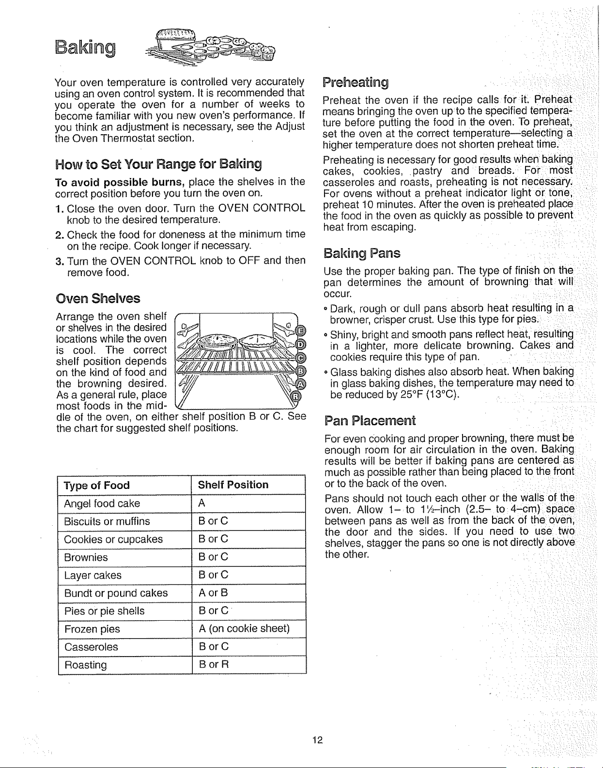
Oven She ves
Arrange the oven shelf
or shelves in the desired
locations while the oven
is cool. The correct
shelf position depends
on the kind of food and
the browning desired.
As a general rule, place
most foods in the mid-
dle of the oven, on either shelf position B or C. See
the chart for suggested shelf positions.
Type of Food Shelf Position
Angel food cake A
'°°t_iscuits or muffins B or C
Cookies or cupcakes B or C
Brownies B or C
..... I ....
Layer cakes B or C
Bundt or pound cakes A or B
Pies or pie shells B or C _
Frozen pies ..... A (oncookie sheet)
Casseroles B or C
Roasting B or R
Preheating
Preheat the oven if the recipe calls for it: Preheat
means bringing the oven upto the specified tempera-
ture before putting the food in the oven. To preheatl =
set the oven at the correct temperature--selecting a
higher temperature does not shorten preheat time:
Preheating is necessary for good results when baking
cakes, cookies, _pastry and breads. For most
casseroles and roasts, preheating is not necessary,
For ovens without a preheat indicator light or tone, : '
preheat 10 minutes. After the oven is preheated place
the food in the oven as quickly as possible to prevent
heat from escaping.
Baking Pans
Use the proper baking pan. The type of finish on the
pan determines the amount of browning that will
occur.
o Dark, rough or dull pans absorb heat resulting in a
browner, crisper crust. Use this type for pies,
oShiny, bright and smooth pans reflect heat, resulting
in a lighter, more delicate browning. Cakes and
cookies require this type of pan.
o Glass baking dishes also absorb heat. When baldng
in glass baking dishes, the temperature may need to
be reduced by 25°F (13°C).
Pan Placement
For even Cooking and proper browning, there must be
enough room for air circulation in the oven. Baking
results will be better if baking pans are centered as
much as possible rather than being placed to the front
or to the back of the oven.
Pans should not touch each other or the walls of the
oven A low t- to l'/_inch (2.5- to 4-cm) space
between pans as well as from the back of the oven, _
the door and the sides. If you need to use two
shelves, stagger the pans so one is not directly above
the other.
12
Baking Guides
When using prepared baking mixes, follow package
recipe or instructions for the best baking results.
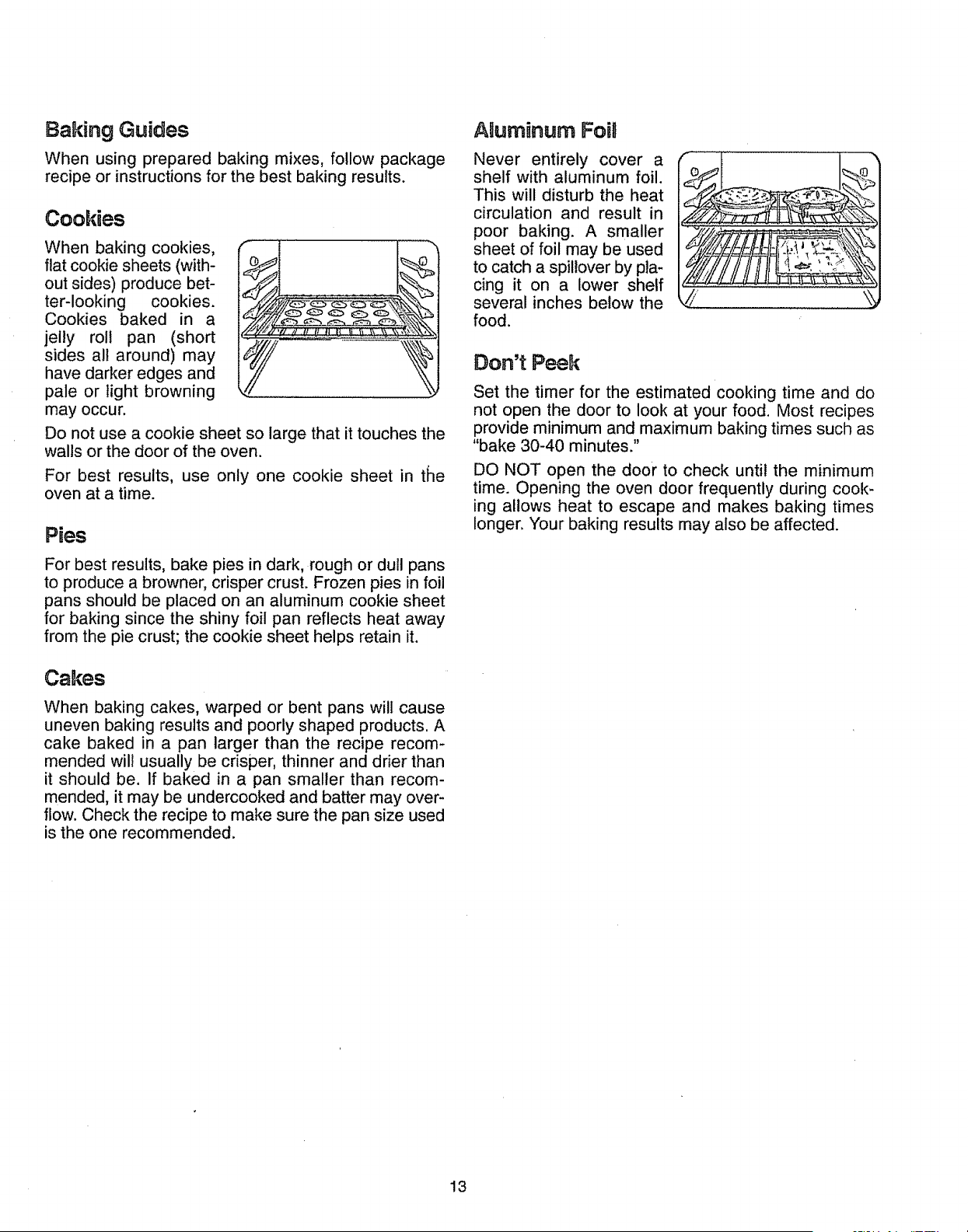
Cookies
When baking cookies,
flat cookie sheets (with-
out sides) produce bet-
ter-looking cookies.
Cookies baked in a
jelly roll pan (short
sides all around) may
have darker edges and
pale or light browning
may occur.
Do not use a cookie sheet so large that it touches the
walls or the door of the oven.
For best results, use only one cookie sheet in the
oven at a time.
Pies
For best results, bake pies in dark, rough or dull pans
to produce a browner, crisper crust. Frozen pies in foil
pans should be placed on an aluminum cookie sheet
for baking since the shiny foil pan reflects heat away
from the pie crust; the cookie sheet helps retain it.
Cakes
When baking cakes, warped or bent pans will cause
uneven baking results and poorly shaped products. A
cake baked in a pan larger than the recipe recom-
mended will usually be crisper, thinner and drier than
it should be. If baked in a pan smaller than recom-
mended, it may be undercooked and batter may over-
flow. Check the recipe to make sure the pan size used
is the one recommended.
A uminum Foil
Never entirely cover a
shelf with aluminum foil.
This will disturb the heat
circulation and result in
poor baking. A smaller
sheet of foil may be used
to catch a spil!over by pla-
cing it on a lower shelf
several inches below the
food.
Don't Peek
Set the timer for the estimated cooking time and do
not open the door to look at your food. Most recipes
provide minimum and maximum baking times such as
"bake 30-40 minutes."
DO NOT open the door to check until the minimum
time. Opening the oven door frequently during cook-
ing allows heat to escape and makes baking times
longer. Your baking results may also be affected.
13
Aoliust the Oven Thermostat==Do #
You may feel that your new oven cooks differently
than the one it replaced. We recommend that you
use your new oven for a few weeks to become more
familiar with it, following the times given in your
recipes as a guide.
If you think your new oven is too hot or too cold,
you can adjust the thermostat yourself. If you think
it is too hot, adjust the thermostat to make it cooler. If
you think it is too cool, adjust the thermostat to make it
hotter.
We do not recommend the use of inexpensive
thermometers, such as those found in grocery
stores, to check the temperature setting of your new
oven. These thermometers may vary 20-40°F
(tl-22°C).
• : /" i_ : !i :":/,:/.
Yourself
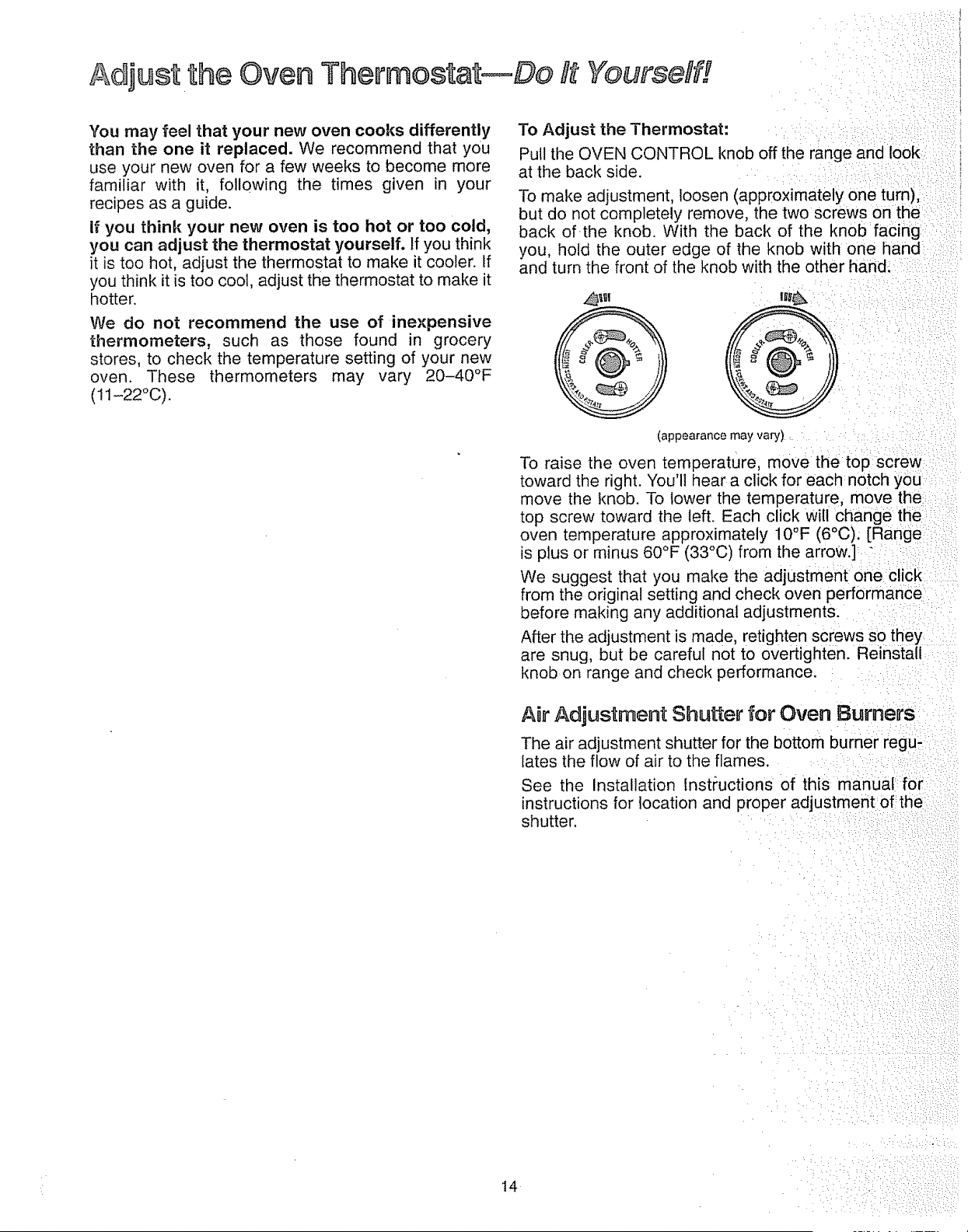
To Adjust the Thermostat: :: i:i::ii :
Pull the OVEN CONTROL knob off the
at the back side.
To make adjustment, loosen (approximately One turn'
but do not completely remove, the two screws on the :
back of the knob. With the back of the knob faCin
you, hold the outer edge of the knob with one hand',
and turn the front of the knob with the other
To raise the oven temperature, move the top:scre_::i :i:::::iI::
toward the right. You II hear a click for each:notch you:: :i ::
move the knob. To lower the temperature move the::!:
top screw toward the left. Each click will Change the :i::i
oven temperature approximately I O°F (6°C): [Rangei:::
is plus or minus 60°F (33°C) from the arrow.]
: : ::: ::::
We suggest that you make the adjustment one click
from the original setting and check oven performance
before making any additional adjustments.
After the adjustment is made, retighten screws sO they
are snug, but be careful not to overtighten.
: i
knob on range and check performance. ::
Air Adjustment Shutter for Oven Burners::: :::::
The air adjustment shutter for the bottom burner regu-:: i:::
lates the flow of air to the flames. ::
See the Installation fnsti;uctions of this manuaf:::f_ri:: :::
instructions for location and proper adjustmentof: thel
shutter, ...... : ::
14
Roasting
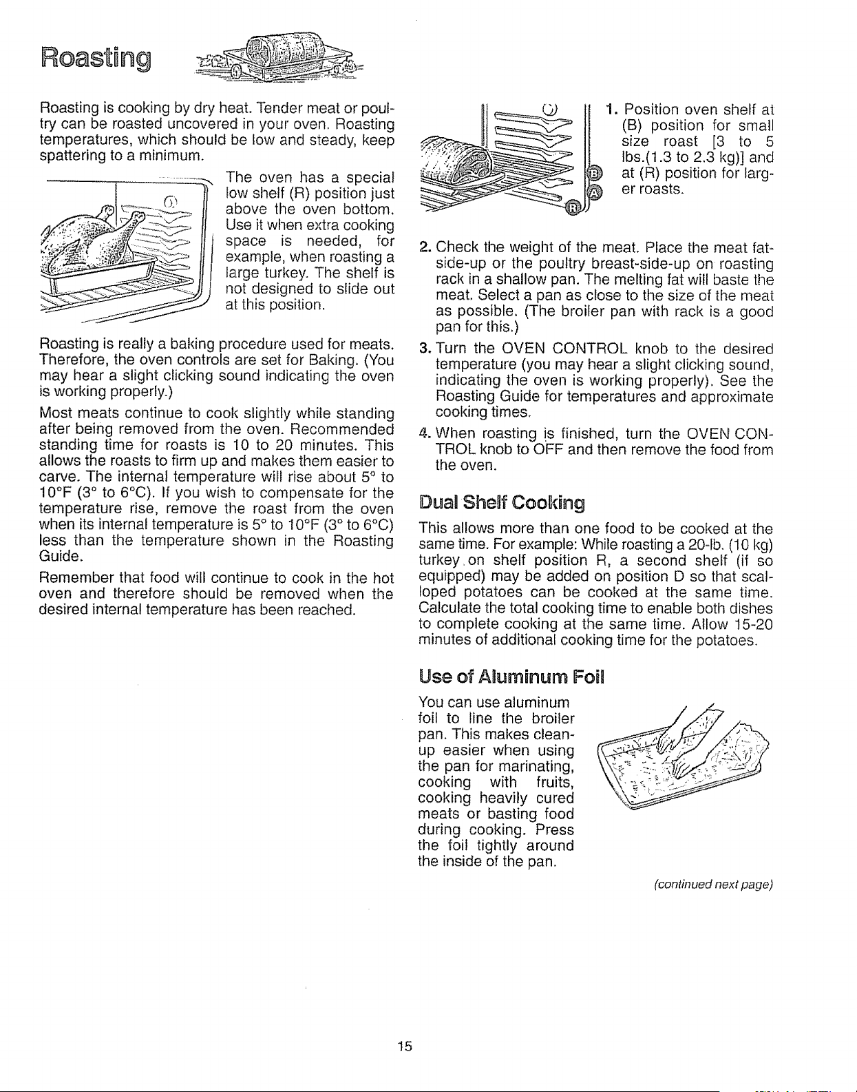
Roasting is cooking by dry heat. Tender meat or poul-
try can be roasted uncovered in your oven. Roasting
temperatures, which should be tow and steady, keep
spattering to a minimum.
The oven has a special
low shelf (R) position just
above the oven bottom.
Use it when extra cooking
i space is needed, for
example, when roasting a
large turkey. The shelf is
not designed to slide out
at this position.
Roasting is really a baking procedure used for meats.
Therefore, the oven controls are set for Baking. (You
may hear a slight clicking sound indicating the oven
is working properly.)
Most meats continue to cook slightly while standing
after being removed from the oven. Recommended
standing time for roasts is 10 to 20 minutes. This
allows the roasts to firm up and makes them easier to
carve. The internal temperature will rise about 5 ° to
10°F (3 ° to 6°C). if you wish to compensate for the
temperature rise, remove the roast from the oven
when its internal temperature is 5° to 10°F (3 ° to 6°C)
less than the temperature shown in the Roasting
Guide.
Remember that food will continue to cook in the hot
oven and therefore should be removed when the
desired internal temperature has been reached.
[_ 1. Position oven shelf at
(B) position for small
size roast [3 to 5
J__ lbs.(1.3to 2,3 kg)] and
._.:_.... at (R) position for larg-
er roasts.
2. Check the weight of the meat. Place the meat fat-
side-up or the poultry breast-side-up on roasting
rack in a shallow pan. The melting fat will baste the
meat. Select a pan as close to the size of the meat
as possible. (The broiler pan with rack is a good
pan for this.)
3. Turn the OVEN CONTROL knob to the desired
temperature (you may hear a slight clicking sound,
indicating the oven is working properly), See the
Roasting Guide for temperatures and approximate
cooking times.
4. When roasting !s finished, turn the OVEN CON-
TROL knob to OFF and then remove the food from
the oven.
Oua Sheff Cooking
This allows more than one food to be cooked at the
same time. For example: While roasting a 20-1b. (10 kg)
turkey.on shelf position R, a second shelf (if so
equipped) may be added on position D so that scal-
loped potatoes can be cooked at the same time.
Calculate the total cooking time to enable both dishes
to complete cooldng at the same time. Allow 15-20
minutes of additional cooking time for the potatoes.
Use of ADuminum Foim
You can use aluminum
foil to line the broiler
pan. This makes clean-
up easier when using
the pan for marinating,
cooking with fruits,
cooking heavily cured
meats or basting food
during cooking. Press
the foil tightly around
the inside of the pan.
(continued next page,)
15
F_oa__in_ (continued)
Frozen Roasts
Frozen roasts of beef, pork, lamb, etc., can be started
without thawing, but allow 15 to 25 minutes per pound
(450 grams) additional time [15 minutes per pound for
roasts under 5 pounds (2.3 kg), more time for larger
roasts].
Make sure poultry is thawed before roasting.
Unthawed poultry' often does not cook evenly. Some
commercial frozen poultry can be cooked successfully
without thawing. Follow the directions given on the
package label.
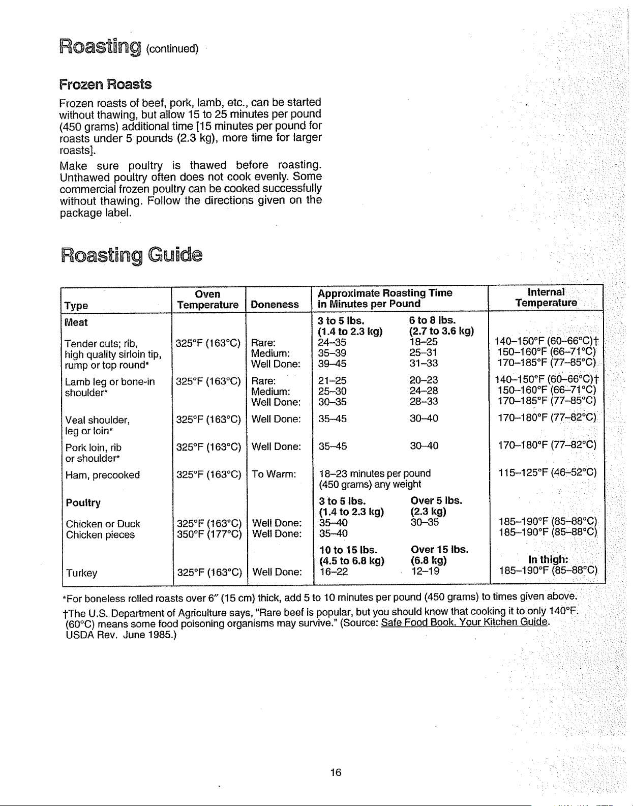
Roasting Guide
Oven Internal
Temperature Temperature
Type
.......... . =............. : ........................
Meat 3 to 5 Ibs.
(1.4 to 2.3 kg)
Tender cuts; rib,
high quality sirloin tip,
rump or top round*
Lamb leg or bone-in
shoulder*
Veal shoulder,
leg or loin*
Pork loin, rib
or shoulder*
325°F (163°C)
325°F (163°C)
325°F (163°C)
325°F (163°C)
325°F (163°C)
325°F (163°C)
350°F (177°C)
...... Approximate Roasting Time
Doneness in Minutes per Pound
6 to 8 Ibs.
(2.7 to
Rare: 24-35 18-25
Medium: 35-39 25-31
Well Done: 39-45 31-33
Rare: 21-25 20-23
Medium: 25-30 24-28
Well Done: 30-35 28-33
Well Done: 35-45 30-40
Well Done: 35-45 30-40
To Warm:
Well Done:
Well Done:
Ham, precooked
Poultry
Chicken or Duck
EChicken pieces
3.6 kg)
18-23 minutes per pound
(450 grams) any weight
3 to 5 Ibs.
(1.4 to 2.3 kg)
35-40
35-40
Over 5 Ibs.
(2.3 kg)
30-35
10 to 15 Ibs.
(4.5 to 6.8 kg)
t 6-22
Over 15 Ibs.
(6.8 kg)
12-19
140-I60°F (60-66°C)t
150-I60°F (66-71 °C)
170-185°F (77-85°C)
140-150°F (60-66°C)t
150-160°F (66"7! °C)
170-185°F (77-85°C)
170-180°F (77-782°C)
170-180°F (77-82°C)
1t5-125°F (46-52°C)
185-190°F (85-88°C)
185-190°F (85-88°C)
In thigh:
Turkey 325°F (163°C) Welt Done: 185-190°F (85-880C)
*For boneless rolled roasts over 6" (15 cm) thick, add 5 to 10 minutes per pound (450 grams) to times given above: =:::i :: :.::::
l'The U.S. Department of Agriculture says, "Rare beef is popular, but you should know that cooking it to only 140°F_
(60°C) means some food poisoning organisms may survive," (Source: Safe Food Book. Your Kitchen Guide_ ::
USDA Rev. June 1985.) : : .........
• • • •• i¸• i !•:: !••:::•_•::•:_•:•_•;!
• _ • _ _ ......... ,__,,,:,:_,_=,:,::_:_:_:_::_:__,_,,i_,i_
• ' i • : •i ::•_/•//i ii•_i/_i:•_ii••
16
Broiling
Broiling is cooking food by direct heat from above the
food. Your range has a convenient compartment
below the oven for broiling, it also has a specially
designed broiler pan and rack that allows the dripping
fat to drain away from the high heat of tlqe gas flame.
Distance from the heat source may be changed by
positioning the broiler pan and rack on one of the
three shelf positions in the broiler compartment--
A (bottom of broiler compartment), B (rniddle) and C
(top).
Most fish and tender cuts of meat can be broiled.
Follow these directions to keep spattering and smok-
ing to a minimum.
The oven and broiler compartment doors must be
closed during broiling.
Turn most foods once during cooking (the exception is
thin fillets of fish; oil one side, place that side down on
the broiler rack and cook without turning until done).
Time the food for about one-half the total cooking
time, turn the food, then continue to cook to the pre-
ferred doneness.
How to Broil
1. The broiler compartment does not need to be pre-
heated for broiling.
2. If the meat has fat or gristle around the edge, cut
vertical slashes through both about 2" (5 cm) apart,
but do not cut into meat. if desired the fat may be
trimmed, leaving a layer about 1/8" (3 ram) thick.
3. Arrange the food on the rack and position the broil-
er pan on the appropriate shelf in the broiler com-
partment. Placing the food closer to flame sears the
exterior and increases the surface browning of
food, but also increases spattering and the possi-
bility of fats and meat juices igniting.
4. Close the broiler door and turn the OVEN CON-
TROL knob to BROIL.
5, Turn the OVEN CONTROL knob to OFR Remove
the broiler pan from the broiler compartment and
serve the food immediately. Do not leave a soiled
broiler pan and rack inside the range.
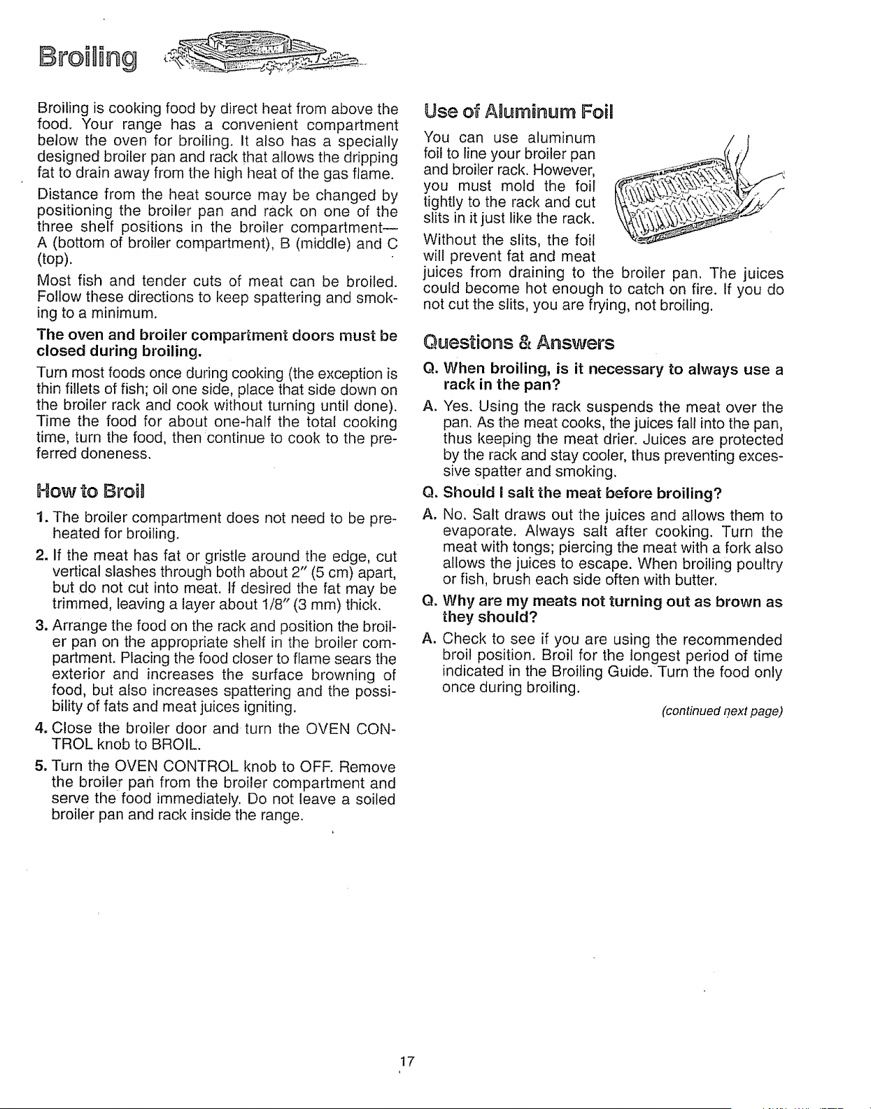
Use of Aluminum Foil
You can use aluminum
foil to line your broiler pan
and broiler rack. However,
you must mold the foil
tightly to the rack and cut
slits in it just like the rack.
Without the slits, the foil
will prevent fat and meat
juices from draining to the broiler pan. The juices
could become hot enough to catch on fire. if you do
not cut the slits, you are frying, not broiling.
Questions & Answers
Q. When broiling, is it necessary to always use a
rack in the pan?
A. Yes. Using the rack suspends the meat over the
pan. As the meat cooks, the juices fall into the pan,
thus keeping the meat drier. Juices are protected
by the rack and stay cooler, thus preventing exces-
sive spatter and smoking.
Q, Should I salt the meat before broiling?
A. No. Salt draws out the juices and allows them to
evaporate. Always salt after cooking. Turn the
meat with tongs; piercing the meat with a fork also
allows the juices to escape. When broiling poultry
or fish, brush each side often with butter.
Q,
A.
Why are my meats not turning out as brown as
they should?
Check to see if you are using the recommended
broil position. Broil for the longest period of time
indicated in the Broiling Guide. Turn the food only
once during broiling.
(continued next page)
17
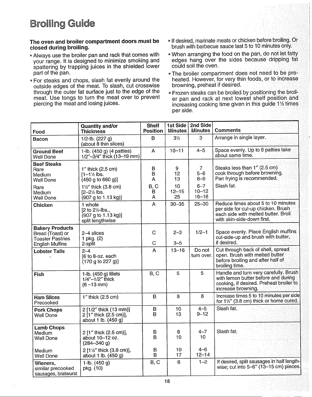
BroiBBngGuBde
The oven and broiler compartment doors must be
closed during broiling.
• Always use the broiler pan and rack that comes with
your range. It is designed to minimize smoking and
spattering by trapping juices in the shielded lower
part of the pan.
o For steaks and chops, slash fat evenly around the
o If desired, marinate meats or chicken befc
brush with barbecue sauce last 5
° When arranging the food on the pani:i do: n0i::l_::i
edges hang over the sides because dri
could soil the oven.
oThe broiler compartment does not need =:to be:
heated. However, for very thin foods, or to increase::::
t : :::
2
outside edges of the meat. To slash, cut crosswise
through the outer fat surface just to the edge of the
meat. Use tongs to turn the meat over to prevent
piercing the meat and losing juices.
increasing cooking time given in this guide 1)½:tim'es
per side. ........ : ::
: ] i
Quantity and/or
Food Thickness
Bacon 1i2-1b. (227 g)
(about 8 thin Slices)
Ground Beef l-lb. (450 g) (4 patties) I
Well Done 1/2 -3/4 thick (13-19 ram!!
Shelf 1st Side
Position Minutes
B 3'/2
A 10-11
2nd Side : ........:
: :: : :
Minutes Comments
3 Arrange in single layer. .... :: i :
4-5 Space evenly, up to 8 patties:take::i: :=
about same time. =:
_ .................... ........ =
Beef Steaks
Rare
Medium
Well Done
Rare
Medium
Wetl Done
1" thick (2.5 cm)
[1-1½ Ibs.
(450 g to 680 g)]
1½" thick (3,8 cm)
[2-2½ Ibs.
B
B
A
B,C
B
9
12
13
10
I2-15
7
5-6
8-9
6-7
10-12
...... (907 g to 1.13 kg)]
A 25
t6-18
Steaks less than 1" (215:cm:):::
cool{ through before browning.
Pan frying s recommended::
Slash fat ......... i: i:: :::i::i::iI
Chicken
Bakery Products
Bread (Toast) or
Toaster Pastries
English Muffins
Lobster Tails
1 whole
[2 to 2½-1bs,,
(907 g to 1.13 kg)]
sPlit !engthwise
2-4 slices
1 pkg. (2)
2-split .............
2-4
[6 to 8-oz. each
(170 g to 227 g)]
Fish l-lb. (450 g) fillets
1/4"-1/2" thick
(6 -13 mm)
Ham Slices = 1" thick (2.5 cm)
Precooked
Pork Chops
.Welt Done
Lamb C'hops
Medium
Well Done
Medium
Well Done
"_Hieners,
similar precooked
sausages, bratwurst
2 [i'/2" thick (13 ram)]
2 [1" thick (2.5 cm)],
about 1 lb. (450 g)
2 [1" thick (2.5 cm)],
about 10-12 oz.
(284-340 g)
2 [11½-thick (3.8 cm)],
about 1 lb. (450 g)
1-1b.(450 g)
pkg. (10)
A
C
C
A
B, €'
B
B
B
B
B
B
B,C
30-35 25'30 " Reduce times aboui"5 to 10 minutes
)er side for cut-up chicken. Brush:::
each side with melted butter. Broil:::::::
with skin-side-down first. :i:
Space evenly. Place English muffinS:
cut-side-up and brush with butter;:i :
if desired.
Cut through back of shell; spread/: i
open, Brush with me ted :::i
before broiling and after half of:
broiling time,: :: ::i :i::::::::::i:::::i:::i::i::i;:::::ii
Handle and turn very carefully_:BrUsh
with lemon butter before and during:::
cooking, if desired: Preheat br0iier to
ncreas e,,browning+:::
B 8 8 Increase times 5 to ! 0 minutes per Sid_
for 1I/£. (3.8 cm) thick or home cUredi
................ • ................ _ ,, , ,,,,,;,
2-3 1/2-1
3-5
13-16 DOnot
turn over.
5 5
10
13
8
10
10
t7
6
4-5 Slash fat.
9-t2
4-7
10
4-6
12-14
1-2
Slash fat.
18
If desired, spl'i'i"sausages in half Iength
wise; cut into 5-6" (13-15cm) Pieces
.... : : :::
: : :
• • L • •L:L •i::•:::::::]•:"
Care and CDeanin9
Proper. care and cleaning are important so your range
wilt give you efficient and satisfactory service. Follow
these directions carefully in caring for it to help assure
safe and proper maintenance.
BE SURE ELECTRICAL POWER IS DISCONNECT-
ED BEFORE CLEANING ANY PART OF YOUR
RANGE.
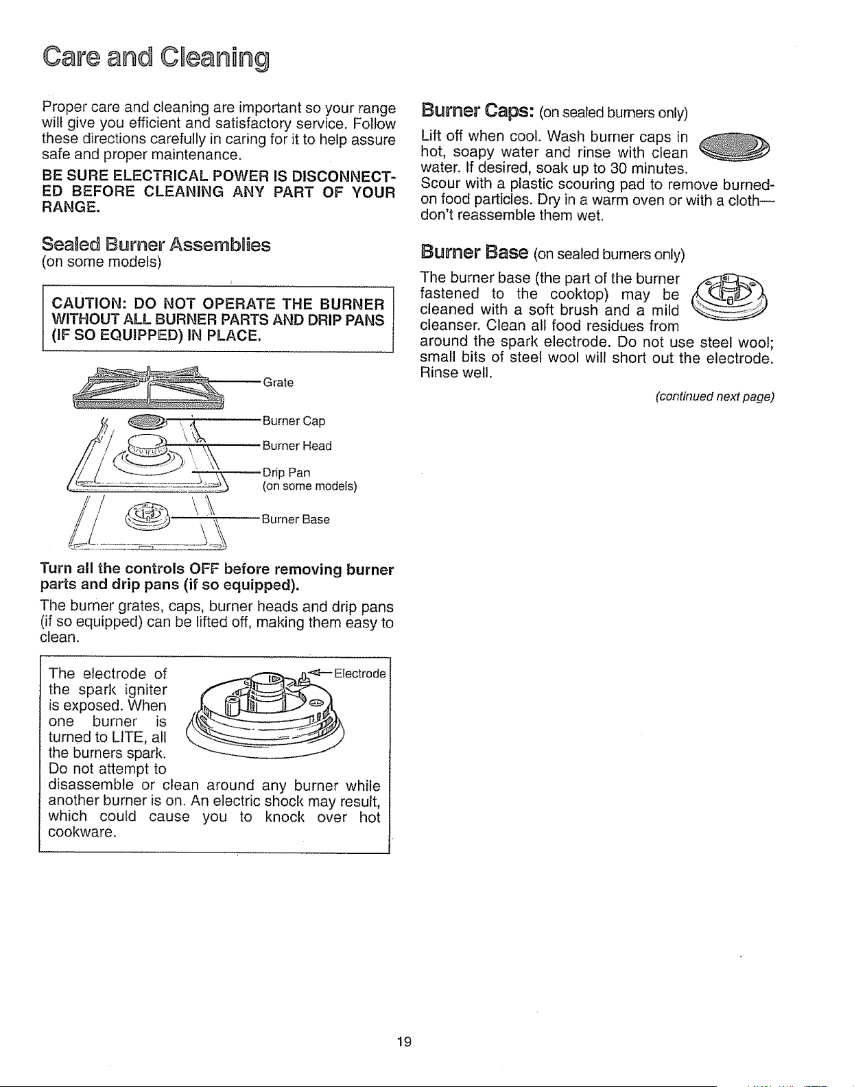
SeaJed Burner Assemblies
(on some models)
CAUTION: DO NOT OPERATE THE BURNER
WITHOUT ALL BURNER PARTS AND DRIP PANS
(IF SO EQUIPPED) IN PLACE,
Grate
;\_ Burner Cap
_=rHead
Pan
(on some models)
' ' 'ix ......Burner Base
Turn all the controls OFF before removing burner
parts and drip pans (if so equipped).
The burner" grates, caps, burner heads and drip pans
(if so equipped) can be lifted off, making them easy to
clean.
Burner Caps: (on sealed burners only)
Lift off when cool. Wash burner caps in
hot, soapy water and rinse with clean
water. If desired, soak up to 30 minutes.
Scour with a plastic scouring pad to remove burned-
on food particles. Dry in a warm oven or with a cloth--
don't reassemble them wet.
Burner Base (on sealed burners only)
The burner base (the part of the burner
fastened to the cooktop) may be
cleaned with a soft brush and a mild
cleanser. Clean all food residues from
around the spark electrode. Do not use steel wool;
small bits of steel wool will short out the electrode.
Rinse well.
(continued next page)
The electrode of
the spark igniter
is exposed. When
one burner is
turned to LITE, all
the burners spark_
Do not attempt to
disassemble or clean around any burner while
another burner is on. An electric shock may result,
which could cause you to knock over hot
cookware.
Electrode
19
CaEe and O[e;_i_}g (continued)
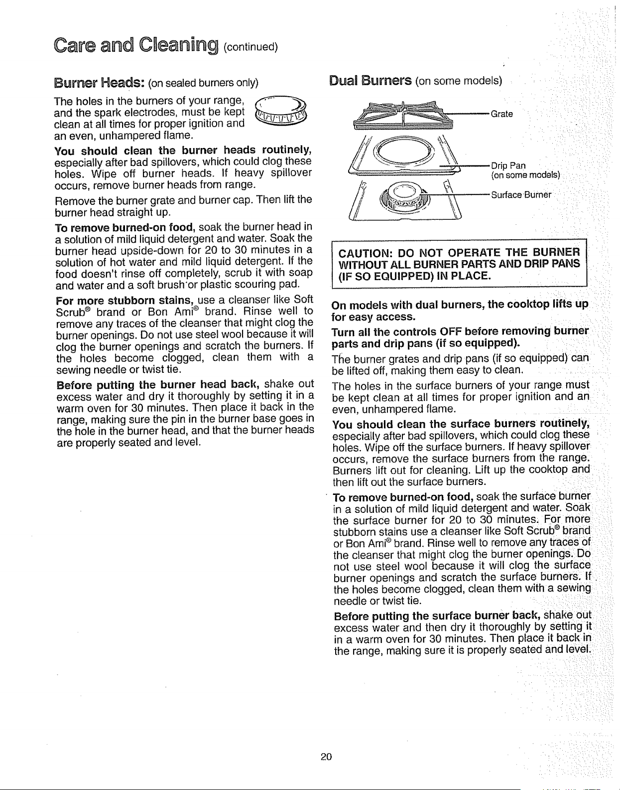
Burner Hesds: (on sealed burners only)
The holes in the burners of your range,
and the spark electrodes, must be kept
clean at all times for proper ignition and
an even, unhampered flame.
You should clean the burner heads routinely,
especially after bad spillovers, which could clog these
holes. Wipe off burner heads. If heavy spi!tover
occurs, remove burner heads from range.
Remove the burner grate and burner cap. Then lift the
burner head straight up.
To remove burned-on food, soak the burner head in
a solution of mild liquid detergent and water. Soak the
burner head upside-down for 20 to 30 minutes in a
solution of hot water and mild liquid detergent, if the
food doesn't rinse off completely, scrub it with soap
and water and a soft brush'or plastic scouring pad.
For more stubborn stains, use a cleanser like Soft
Scrub e brand or Bon Ami ® brand. Rinse well to
remove any traces of the cleanser that might clog the
burner openings. Do not use steel wool because it will
clog the burner openings and scratch the burners, tf
the holes become clogged, clean them with a
sewing needle or twist tie.
Before putting the burner head back, shake out
excess water and dry it thoroughly by setting it in a
warm oven for 30 minutes. Then place it back in the
range, making sure the pin in the burner base goes in
the hole in the burner head, and that the burner heads
are properly seated and level.
[}U81 BurNers (on some models)
!
_, _i_,_:,_/_IT_I_ i
• ,::: i_i_:i_I:,:
•• • i • : : : ••i ¸
: • : / J i::• /•i ••:•• • :•
Grate ..... :
: : :
,._' • _: _ rJ_Pan
-- (on some models): :
'i3 i: i
CAUTION: DO NOT OPERATE THE BURNER
WITHOUT ALL BURNER PARTS AND DRIP PANS
(IF SO EQUIPPED) IN PLACE.
On models with dual burners, the cooktop lifts upl
for easy access.
Turn all the controls OFF before removing =burner I:=
parts and drip pans (if so equipped). :
The burner grates and drip pans (if so equipped)can
be lifted off, making them easy to clean ...... .......: .....
The holes in the surface burners of your range must
be kept clean at all times for proper ignition and anll :
even, unhampered flame.
You should clean the surface burners routinely,
especially after bad spillovers, which could clog these
holes. Wipe off the surface burners. If heavy spillover
occurs, remove the surface burners from the range:
Burners lift out for cleaning. Lift up the cooktop and
then lift out the surface burners .... _.,
" To remove burned-on food, soak the surface burnei ::::
in a solution of mild liquid detergent and water. Soak_ ::_:
the surface burner for 20 to 30 minutes_ For more::
stubborn stains use a cleanser like Soft Scrub e brand
or Bon Ami ® brand. Rinse well to remove any traces0f
the cleanser that might clog the burner openings:Do
not use steel wool because it will clog the surface i
burner openings and scratch the surface burners.
the hoes become clogged clean them with a sewing
needle or twist tie.
Before putting the surface burner back,
excess water and then dry it thoroughly by setting it : i
in a warm oven for 30 minutes. Then place it back in:_ i:=:;i:
the range, mak ng sure it is properly seated and level!::=: :=:_ii:,ii=
20
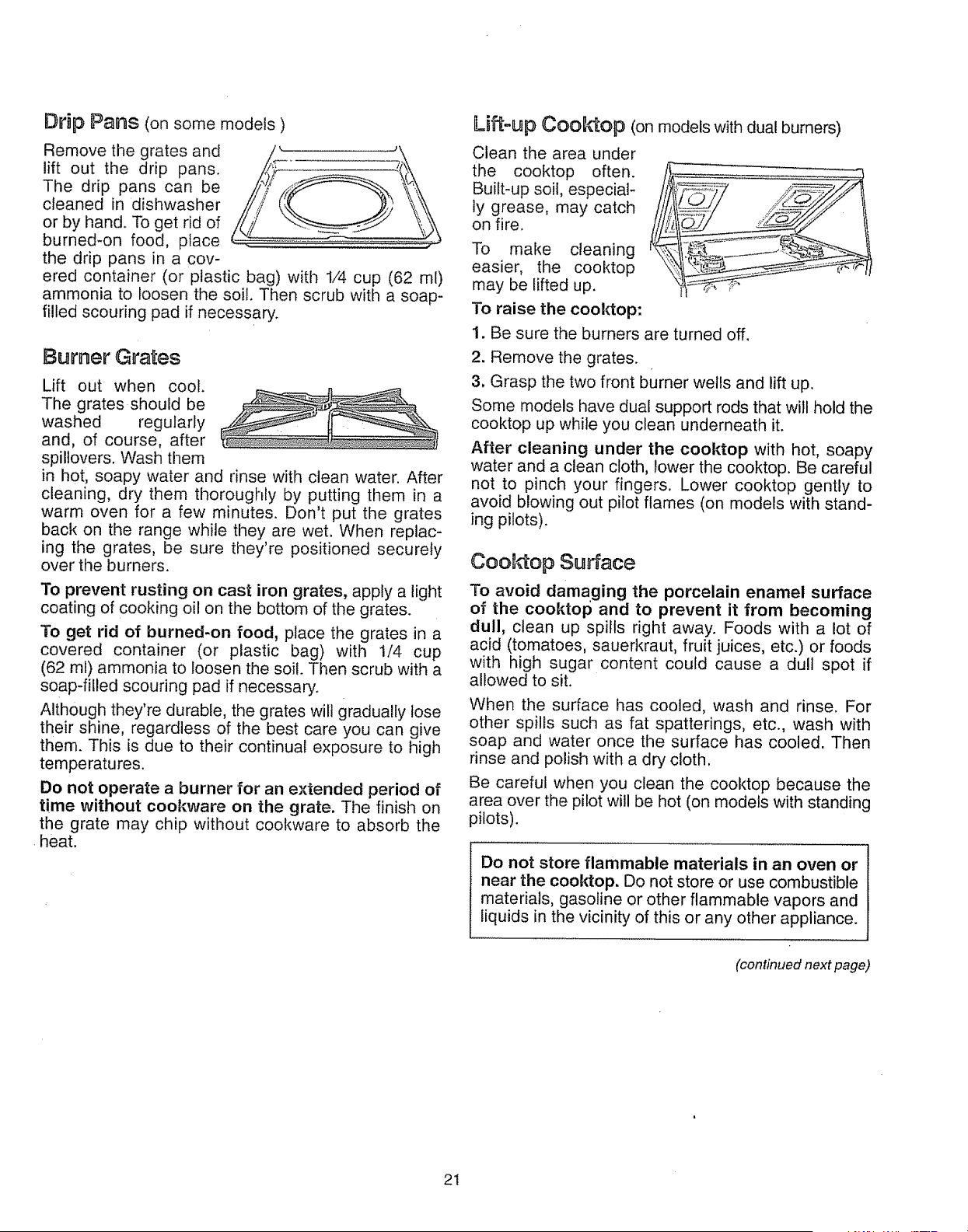
Drip Pans (onsome models )
Remove the grates and
lift out the drip pans.
The drip pans can be
cleaned in dishwasher
or by hand. To get rid of
burned-on food, place _.
the drip pans in a cov-
ered container (or plastic bag) with 1/4 cup (62 ml)
ammonia to loosen the soil. Then scrub with a soap-
filled scouring pad if necessary.
Burner Grates
Lift out when cool.
The grates should be
washed regularly
and, of course, after
spiltovers. Wash them
in hot, soapy water and rinse with clean water. After
cleaning, dry them thoroughly by putting them in a
warm oven for a few minutes. Don't put the grates
back on the range while they are wet. When replac-
ing the grates, be sure they're positioned securely
over the burners.
To prevent rusting on cast iron grates, apply a light
coating of cooking oil on ti_e bottom of the grates.
To get rid of burned-on food, place the grates in a
covered container (or plastic bag) with 1/4 cup
(62 ml) ammonia to loosen the soil. Then scrub with a
soap-filled scouring pad if necessary.
Although they're durable, the grates wilt gradually lose
their shine, regardless of the best care you can give
them. This is due to their continual exposure to high
temperatures.
Do not operate a burner for an extended period of
time without cookware on the grate. The finish on
the grate may chip without cookware to absorb the
heat.
Lift-up Cooktop (onmodels with dual burners)
Clean the area under
the cooktop often.
Built-up soil, especial-
ly grease, may catch
on fire.
To make cleaning
easier, the cooktop
may be lifted up.
To raise the cool{top:
1. Be sure the burners are turned off.
2. Remove the grates.
3, Grasp the two front burner wells and lift up.
Some models have dual support rods that will hold the
cooktop up while you clean underneath it.
After cleaning under the cooktop with hot, soapy
water and a clean cloth, lower the cooktop. Be careful
not to pinch your fingers. Lower cooktop gently to
avoid blowing out pilot flames (on models with stand-
ing pilots).
Cooktop Surface
To avoid damaging the porcelain enamel surface
of the cooktop and to prevent it from becoming
dull, clean up spills right away. Foods with a lot of
acid (tomatoes, sauerkraut, fruit juices, etc.) or foods
with high sugar content could cause a dull spot if
allowed to sit.
When the surface has cooled, wash and rinse. For
other spills such as fat spatterings, etc., wash with
soap and water once the surface has cooled. Then
rinse and polish with a dry cloth,
Be careful when you clean the cooktop because the
area over the pilot will be hot (on models with standing
pilots).
Do not store flammable materials in an oven or
near the cooktop. Do not store or use combustible
materials, gasoline or other flammable vapors and
liquids in the vicinity of this or any other appliance.
(continued next page)
21
Care and C0eanin9 (continued)
Oven Air Vents
Never block the vents (air openings) of the
range. They provide the air inlet and outlet that are
necessary for the range to operate properly with
correct combustion. Air openings are located at the
rear of the cooktop, at the top and bottom of the
oven door, and at the bottom of the range, under
the kick panel, storage drawer or broiler drawer
(depending on the model).
BroiDer Pan and Rack
After broiling, remove the broiler pan from the oven
or broiler compartment (depending on your model).
Remove the rack from the pan. Carefully pour out
grease from the pan into a proper container. Wash
and rinse the broiler pan and rack in hot water with a
soap-filled or plastic scouring pad.
If food has burned on, sprinkle the rack with deter-
gent while hot and cover with wet paper towels or a
dishcloth. Soaking the pan will remove burned on
foods.
Both the broiler pan and rack can also be cleaned in
the dishwasher.
Do not store a soiled broiler pan and rack anywhere in
the range.
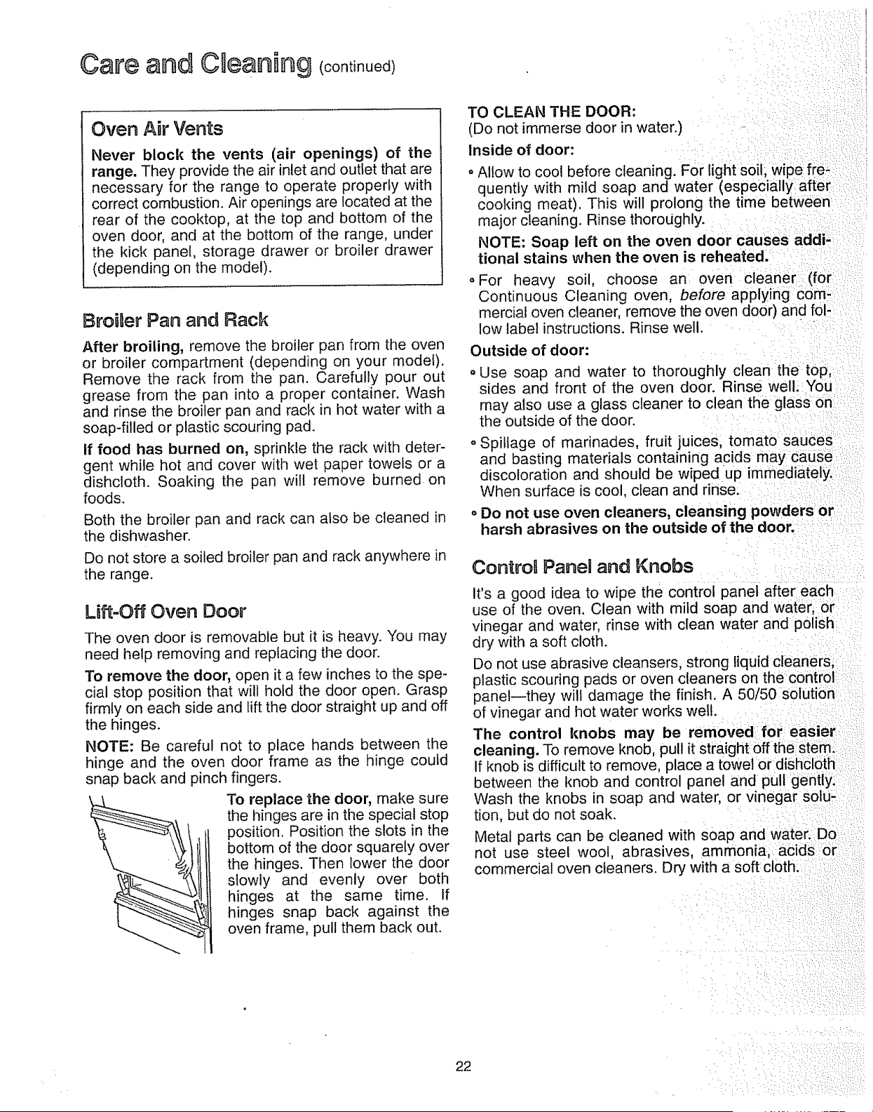
Lift-Off Oven Door
The oven door is removable but it is heavy. You may
need help removing and replacing the door.
To remove the door, open it a few inches to the spe-
cial stop position that will hold the door open. Grasp
firmly on each side and lift the door straight up and off
the hinges.
NOTE: Be careful not to place hands between the
hinge and the oven door frame as the hinge could
snap back and pinch fingers.
To replace the door, make sure
the hinges are in the special stop
position. Position the slots in the
bottom of the door squarely over
the hinges. Then lower the door
slowly and evenly over both
hinges at the same time. If
hinges snap back against the
oven frame, pull them back out.
TO(DoCLEANnotimmerseTHEdoorDOOR:inwater.) i
Inside of door:
= Allow to cool before cleaning. For light soili wi
quently with mild soap and water (especi
cooking meat). This will prolong the time :::::::::::::::::::::::
major cleaning. Rinse thoroughly. ......
NOTE: Soap left on the oven door
tional stains when the oven is reheated.:
-For heavy soil, choose an:
Continuous Cleaning oven, before applying corn,: ::: ::
mercial oven cleaner, remove the oven door) and fol_:i:::::i:i:
low label instructions. Rinse well.
Outside of door: .... :
°Use soap and water to thoroughly
sides and front of the oven door. Rinse welli You
may also use a glass cleaner to clean the
the outside of the door. : :
o Spillage of marinades, fruit juices
1::::: s:Uc::::::: :::::::::
and basting materials containing acids may cause: :::::::::::::
d scot:ration and should be wiped Up immediately:::;::::::?:
When surface is cool, clean and rinse; :::
Do not use oven cleaners, cleansing
harsh abrasives on the outside of the door.:: :::
ControB Pane: and Knobs ......:: :::::::::::::::::::
It's a good idea to wipe the control panel after each :::::::::
use of the oven. Clean with mild soap and water, or: :::::
vinegar and water, rinse with clean water and polish: i:ii
dry with a soft cloth.
Do not use abrasive cleansers, strong liquid cleaners:;::::::
plastic scouring pads or oven cleaners on the c0ntroL::::: :
pane!--they will damage the finish. A 50/50 s01uti6n:::::::::
of vinegar and hot water works well.
The control knobs may be
cleaning. To remove knob, pull it straight 6ff the stemll
f knob s difficu t to remove, place a towel 0r diShcl6th: : ii
between the knob and control panel and pull gently: :
Wash the knobs n soap and water, or vinegar Solu- =: :
tion, but do not soak. :: : :
Met: parts can be cleaned with soap and ======================
not use steel wool, abrasves, ammonia acids::or::::_::: ::
commercial oven cleaners, Dry with a soft cioth:: :::
=
22
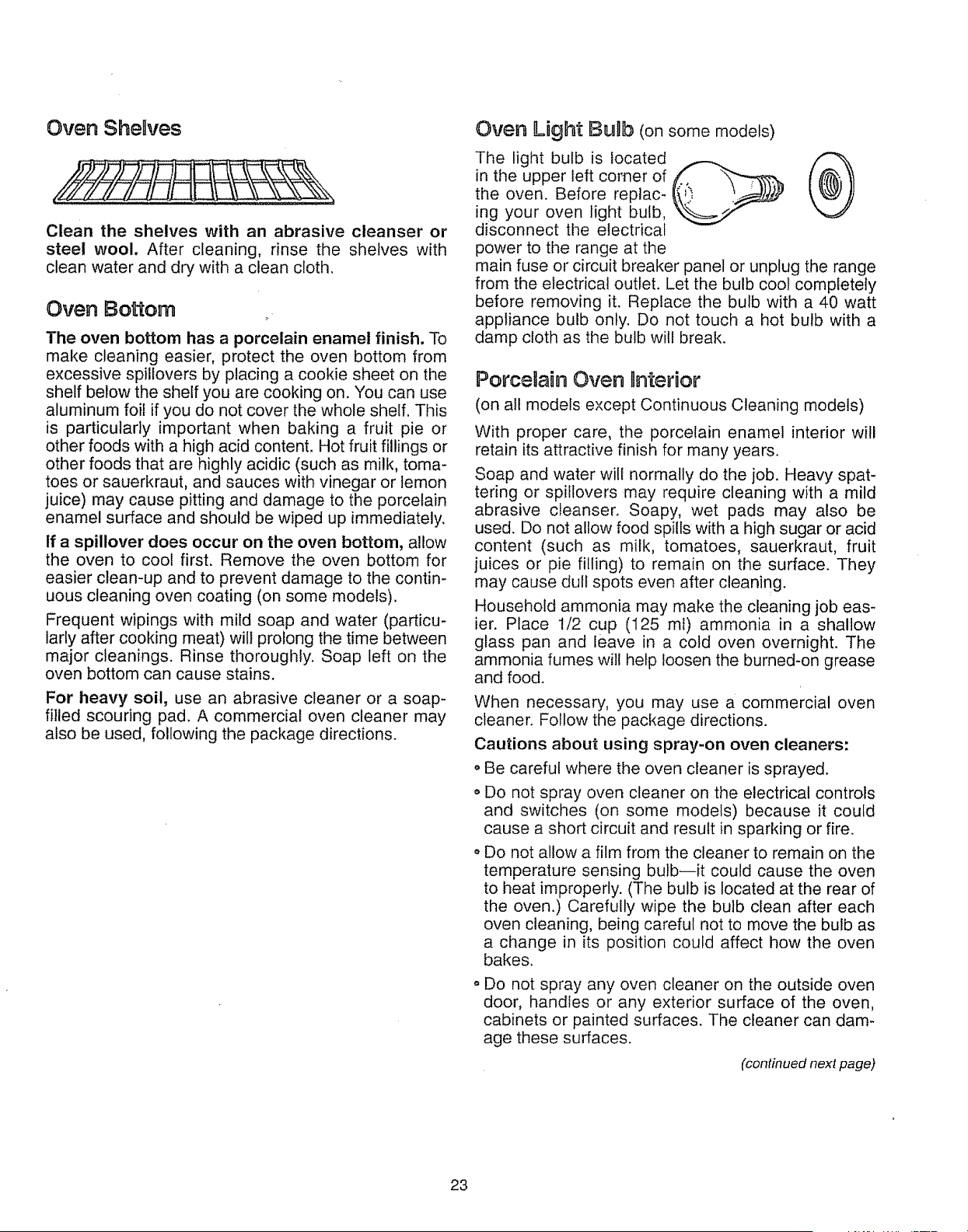
Oven $heDvee
Clean the shelves with an abrasive cleanser or
steel wool. After cleaning, rinse the shelves with
clean water and dry with a clean cloth.
Oven Bottom
The oven bottom has a porcelain enamel finish. To
make cleaning easier, protect the oven bottom from
excessive spillovers by placing a cookie sheet on the
shelf below the shelf you are cooking on. You can use
aluminum foil if you do not cover the whole shelf. This
is particularly important when baking a fruit pie or
other foods with a high acid content. Hot fruit fillings or
other foods that are highly acidic (such as milk, toma-
toes or sauerkraut, and sauces with vinegar or lemon
juice) may cause pitting and damage to the porcelain
enamel surface and should be wiped up immediately.
If a spillover does occur on the oven bottom, allow
the oven to cool first. Remove the oven bottom for
easier clean-up and to prevent damage to the contin-
uous cleaning oven coating (on some models).
Frequent wipings with mild soap and water (particu-
larly after cooking meat) will prolong the time between
major cleanings. Rinse thoroughly. Soap left on the
oven bottom can cause stains.
For heavy soil, use an abrasive cleaner or a soap-
filled scouring pad, A commercial oven cleaner may
also be used, following the package directions.
Oven Light BuJb (onsome models)
The light bulb is located
in the upper left comer of
the oven. Before replac-
ing your oven light bulb,
disconnect the electrical
power to the range at the
main fuse or circuit breaker panel or unplug the range
from the electrical outlet. Let the bulb cool completely
before removing it. Replace the bulb with a 40 watt
appliance bulb only. Do not touch a hot bulb with a
damp cloth as the bulb will break.
Porceaain Oven Onterior
(on all models except Continuous Cleaning models)
With proper care, the porcelain enamel interior will
retain its attractive finish for many years.
Soap and water will normally do the job. Heavy spat-
tering or spillovers may require cleaning with a mild
abrasive cleanser. Soapy, wet pads may also be
used. Do not allow food spills with a high sugar or acid
content (such as milk, tomatoes, sauerkraut, fruit
juices or pie filling) to remain on the surface. They
may cause dull spots even after cleaning.
Household ammonia may make the cleaning job eas*
ier. Place 1/2 cup (125 ml) ammonia in a shallow
glass pan and leave in a cold oven overnight. The
ammonia fumes will help loosen the burned-on grease
and food.
When necessary, you may use a commercial oven
cleaner. Follow the package directions.
Cautions about using spray-on oven cleaners:
o Be careful where the oven cleaner is sprayed.
o Do not spray oven cleaner on the electrical controls
and switches (on some models) because it could
cause a short circuit and result in sparking or fire.
o Do not allow a film from the cleaner to remain on the
temperature sensing bulb--it could cause the oven
to heat improperly. (The bulb is located at the rear of
the oven.) Carefully wipe the bulb clean after each
oven cleaning, being careful not to move the bulb as
a change in its position could affect how the oven
bakes.
o Do not spray any oven cleaner on the outside oven
door, handles or any exterior surface of the oven,
cabinets or painted surfaces. The cleaner can dam-
age these surfaces.
(continued next page)
23
Care and CBeaning (continued)
Speciat Care of the Continuous-CJeaning
Oven Bnterior (on somemodels)
The Continuous-Cleaning Over1 cleans itself while
cooking. The oven walls are finished with a special
coating that cannot be cleaned in the usual manner
with soap, detergents, steel wool pads, commercial
oven cleaners, coarse abrasive pads or coarse brush-
es. Use of such cleansers and/or the use of oven
sprays will cause permanent damage.
The special coating is a porous ceramic material,
which is dark in color and feels slightly rough to the
touch. If magnified, the surface would appear as
peaks, valleys and sub-surface "tunnels." This rough
finish tends to prevent grease spatters from forming
little beads or droplets that run down the side walls of
a hard-surface oven liner, leaving unsightly streaks
that require hand cleaning. Instead, when spatter hits
the porous finish, it is dispersed and partially
absorbed. This spreading action increases the expo-
sure of oven soil to heated air and makes it somewhat
less noticeable.
Soil may not disappear completely and at some
time after extended usage, stains may appear that
cannot be removed.
The special coating works best on small amounts
of spatter. It does not work well with larger spills,
especially sugars, egg or dairy mixtures. The oven
bottom does not have the continuous cleaning oven
coating and can be removed and cleaned with a com-
mercial oven cleaner.
This special coating is not used on the oven
shelves, oven bottom or the inside of the oven
door. Remove these to clean with a commercial
oven cleaner to prevent damaging the Continuous-
Cleaning Oven coating.
Make sure the oven bottom is in place before
you turn the oven on for any reason.
Use care in removing and replacing the oven
bottom and shelves and in placing and removing
dishes and food to avoid scratching, rubbing or other-
wise damaging the porous finish on the oven walls.
mend rubber gloves be worn when Cleanin
2. Remove shelvesand cookware: :: ....
3, Soil visibility may be reduced by operating: the:oven::::
at 400F (204 C). Close the door and turn OVEN:I:::: :::_:
CONTROL knob to 400 F (204 C). Timef0r at: least: i::i:i::::::
before replacing the oven shelves. :
4. If a spitiover or heavy soiling occurs on the porous i::i:
surface, as soon as the oven has cooled; remove :
as much of the soil as possible using: a small:;:
amount of water and a stiff-bristle nylon brush. Use:
water sparingly and change it frequently, keeping itl
as clean as possible, and be sure to blot it up with
paper towels, cloths or sponges. Do not rub or
scrub with paper towels, cloths or sponges; since
they will leave unsightly lint on the oven finish. If
water leaves a white ring on the finish as it dries;
apply water again and blot it with a clean sponge,
starting at the edge of the ring and working toward
the center.
The oven bottom has a porcelain enamel finish:
The oven bottom comes out for cleaning away from
the Continuous-Cleaning Oven.
The inside of the oven door has a porcelain enam-
el finish. The oven door lifts off for cleaning away
from the Continuous-Cleaning Oven. For instructions
on how to clean the inside of the oven door refer: to
the Lift-Off Oven Door section.
Do not use soap, detergent, steel wool pads,
commercial oven cleaner, silicone: oven
sprays, coarse pads or coarse brushes on the
porous surface. These products will spot, clog
and damage the porous surface and reduce its
ability to work.
Do not scrape the porous surface with a knife
or spatula--they could permanently damage the
finish.
24
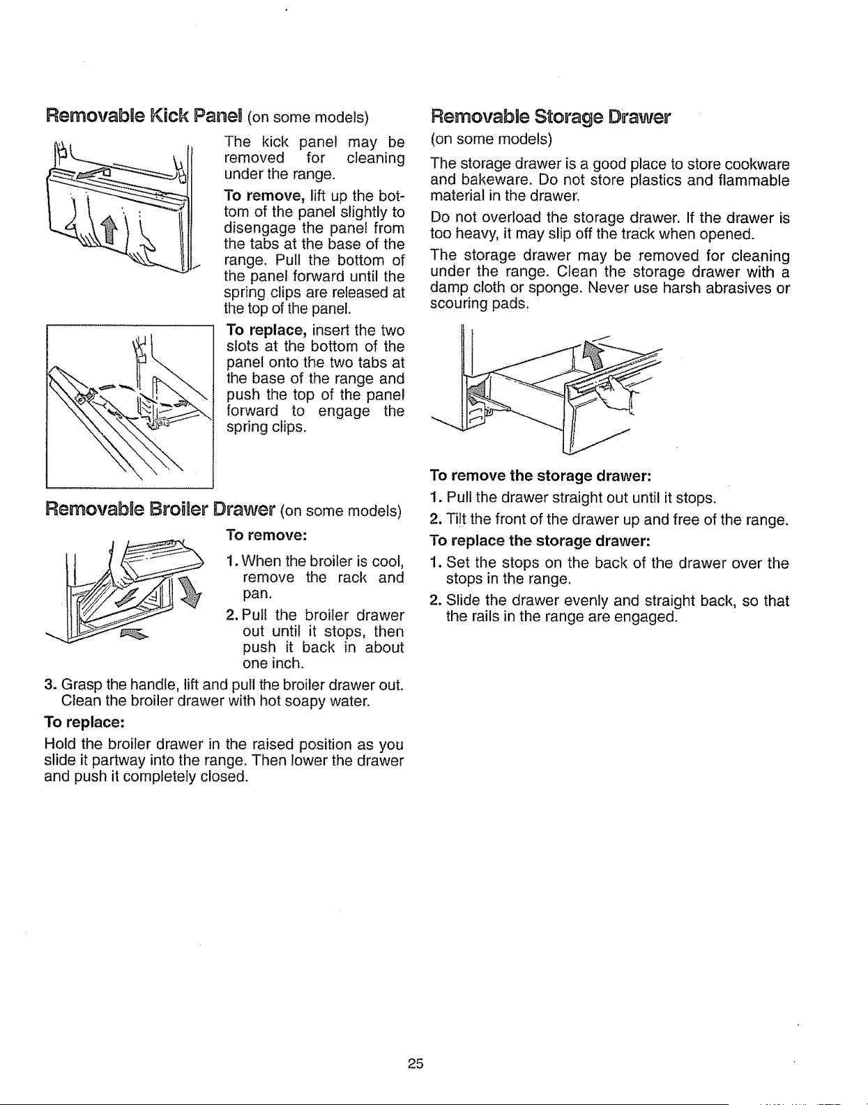
Removable Kick Panel (on some models)
The kick panel may be
removed for cleaning
under the range.
To remove, lift up the bot-
tom of the panel slightly to
disengage the panel from
the tabs at the base of the
range. Pull the bottom of
the panel forward until the
spring clips are released at
the top of the panel.
To replace, insert the two
slots at the bottom of the
panel onto the two tabs at
the base of the range and
push the top of the panel
forward to engage the
spring clips.
Removable Storage D_'awer
(on some models)
The storage drawer is a good place to store cookware
and bakeware. Do not store plastics and flammable
material in the drawer.
Do not overload the storage drawer. If the drawer is
too heavy, it may slip off the track when opened.
The storage drawer may be removed for cleaning
under the range. Clean the storage drawer with a
damp cloth or sponge. Never use harsh abrasives or
scouring pads.
Removabge BroiBer Drawer (on some models)
To remove:
1. When the broiler is cool,
remove the rack and
pan.
2. Pull the broiler drawer
out until it stops, then
push it back in about
one inch.
3. Grasp the handle, lift and pull the broiler drawer out.
Clean the broiler drawer with hot soapy water.
To replace:
Hold the broiler drawer in the raised position as you
slide it partway into the range. Then lower the drawer
and push it completely closed.
To remove the storage drawer:
1. Pull the drawer straight out until it stops.
2. Tilt the front of the drawer up and free of the range.
To replace the storage drawer:
1. Set the stops on the back of the drawer over the
stops in the range.
2, Slide the drawer evenly and straight back, so that
the rails in the range are engaged.
25
INSTALLATION
FOR YOUR SAFETY
If you smell gas:
1. Open windows.
2. Don't touch electrical switches.
3. Extinguish any open flame.
4. Immediately call your gas supplier.
FOR YOUR SAFETY
Do not store or use combustible materials, gaso-
line or other flammable vapors and liquids in the
vicinity of this or any other appliance.
BEFORE YOU BEGIN
Read these instructions completely and carefully.
IMPORTANT: Save these instructions for the local
electrical inspector's use.
INSTALLER: Leave these instructions with the
appliance after installation is completed.
CONSUMER: Keep this Use and Care Manual and
the Installation Instructions for future use.
This appliance must be properly grounded.
WARNING
INSTRUCTIONS : :::
_, ,,, ':i):::,:i,:_::,:::::=:_);i)__ii_::':i_i:_ii:i:,iii:i_
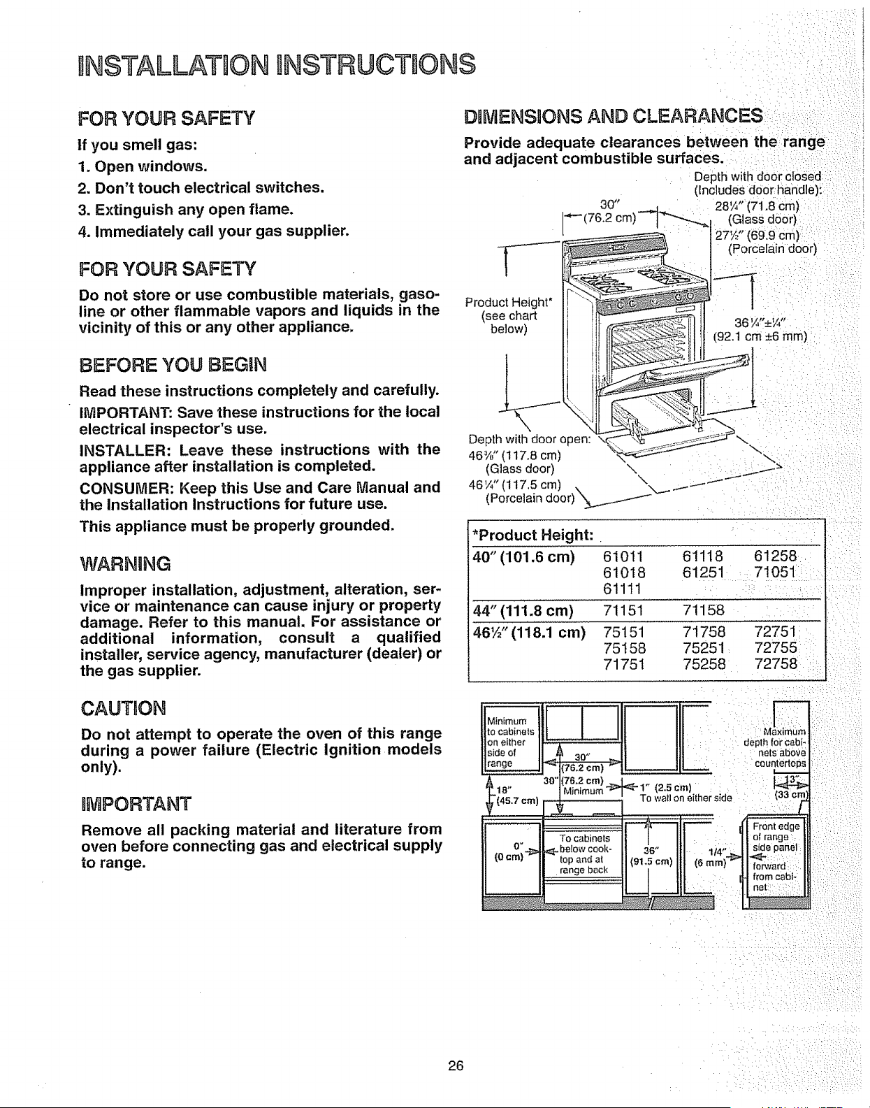
DI_IENSIONS AND CLEARANCES:: :;:::
Provide adequate clearances between
and adjacent combustible surfaces.:
(Includes door handle)!: i i: :i:
30"
I /t
28¼ (71.8cm) :::: ............
..... 27½ (69=.9 ::::i: ::::!::::::::=:i:i::
Product Height*
(see chart ,, .......... ::
36 ¼ +'/; ......
below) (92.1 cm ±6 ram):
i:i ii I
Depth with door open:
46%'(117.8cm) _
(Glass door) \
46 '/4 (117.5cm) \ _.i : : : ::=:
(Porcelain door) "-_
Improper installation, adjustment, alteration, ser-
vice or maintenance can cause injury or property
damage. Refer to this manual. For assistance or
additional information, consult a qualified
installer, service agency, manufacturer (dealer) or
the gas supplier.
CAUTION
Do not attempt to operate the oven of this range
during a power failure (Electric Ignition models
only).
IMPORTANT
Remove all packing material and literature from
oven before connecting gas and electrical supply
to range.
*Product Height:.
40" (101.6 cm) 61011
61018
61111
44"(111.8 cm) 71151
46W'(118.1 cm) 75151
75158
71751
Minimum LL_
to cabinets
on either
side of
range _ ' 30" .
(76.2 cm) "
30" (76.2 cm)
18" Minimum
(45.7 cm) _ ....
.... , :i::i :::::i:i:!i:::i:i::':,_
61"118 ""'6"125_ :::::::: ::
61251 71051:: ::: I: ;:: ::::::::
71758 72751
75251 727551 _
75258 72758: _:I
: : : : counted0ps ;: : :::! :::
To cabinels
0" _ below cook- 36" 1,
(0 cm) -_ top and a! {91.5 cm) (6 m
26
IMPORTANT SAFEWYINSTRUCTIONS
oInstallation of this range must conform with local
codes, orin the absence of local codes, with the
National Fuel Gas Code, ANS! Z223.1, latest edi-
tion. in Canada, installation must conform with
the:current Natural Gas Installation Code,
CANICGA, B149.1 or the current Propane
Installation Code, CANICGA-B149.2 and with
local :codes where applicable.
This :range has been design-certified by the American
Gas Association according to ANSI Z21.1, latest edi-
o If cabinets are placed above the range, allow a mini-
mum clearance of 30" (76,2 cm) between the cook-
ing surface and the bottom of unprotected cabinets
o If a 30,(76.2 cm) clearance between cooking sur-
face and overhead combustible material or metal
cabinets cannot be maintained, protect the under-
side 0f:the cabinets above the cooking top with not
less than 1/4":(6 mm) insulating millboard covered
with sheet metal not less than 0,0122" (.31 mm)
thick.
tion and Canadian Gas Association according to
CAN/CGA-I.1 latest edition. As with any appliance
using gas and generating heat, there are certain safe-
ty precautions you should follow. You will find these
precautions in the Important Safety Instructions sec-
tion :in tlle front of this manual. Read them carefully.
o Have your range installed by a qualified installer or
service :technician.
.Your range must be electrically grounded in accor-
dance with local codes or, in the absence of local
codes, in accordance with the National Electrical
Code':(ANSI/NFPA 70, latest edition). In Canada,
electrical grounding must be in accordance with the
currentCSA-C22.1 Canadian Electrical Code Part 1
and/or local codes. See Electrical Connections in
Clearance between the cooking surface and protect-
ed cabinets MUST NEVER BE LESS THAN 24" (61
cm)• The _vertical distance from the plane of tl_e
cooking surface to the bottom of adjacent overhead
cabinets extending closer than 1" (2.5 cm) to the
plane of the range sides must not be less than 18"
(45.7 cm),:(See the Dimensions and Clearances
illustration in this section,)
oCAUTION: Items of interest to children should not
be stored in cabinets above a range or on tile back-
splash of a range--children climbing on the range to
reach items could be seriously injured.
WARNBNG
All ranges can tip and injury could
this section, result. To prevent accidental tipping of
Before installing your range on linoleum or any other : the range, attach an approved Anti-Tip
synthetic floor covering, make sure the ffoor covering device to the wall. :(See Installing the
can withstand 180°F (82°C) without shrinking, warp-Anti-Tip Device in this section.) To
ing or discoforing. Do not install the range over car- check: if the device is installed and
peting unless a sheet of 1/4" (6 turn) thick plywood engaged properly, carefully tip the
or Similar insulator is between
....... placed the ra_ige and range iforward.:The Anti-Tip device
carpeting. ...... should engage and prevent the range
o Make sure the wall coverings around the range can from tipping over.
withstand heat generated by the range :up to 200°E If you :pull the range out from the wall
(93QC). f0r any reason, make sure the Anti-Tip
o Avoid placing cabinets above the range. To reduce device is engaged when you push the
the hazard caused by reaching over the open flames range back against the wat
of operating burners, install a ventilation hood over °For your safety, never use your range for warming
the range that projects forward at least 5 (12.7 cm) or heating the room. Your oven and cooktop are not
beyond the front of the cabinets. :: designed to heat your kitchen. Top burners should
oThe ventilating hood :must be constructed of sheet not be: operated without cookware on the grate.
metal not less than 0.0122" (.31 ram) thick. Install Such abuse could result in fire and damage to your
above the cooking top with a clearance of not less range and will void your warranty.
than 1/4": (6 ram) between tile hood and the under- oDo not store or use combustible materials, gasoline
side of the combustible material or metal cabinet, or other flammable vapors and liquids in the vicinity
:The hood must be at least as wide as the appliance of this or any other appliance. Explosions or fires
and centered over the appliance. Clearance could result.
between the cooking surface and the ventilation o Do not use oven for a storage area. Items stored in"
hood surface MUST: NEVER BE LESS THAN 24" the oven can ignite•
(61 cm). o Do not let cooking grease or other flammable mate-
EXCEPTION: Installation of a listed microwave rials accumulate in or near the range•
oven or cooking appliance over the cooktop :shall
conform to the installation instructions packed with
that appliance.
27
mnsta lation nstructions
GENERAL
o See Dimensions and Clearances in this section for
all rough-in and spacing dimensions. These dimen-
sions must be met for safe use of your range. The
location of the electrical outlet and pipe opening (see
Gas Pipe and Electric Outlet Locations) may be
adjusted to meet specific requirements.
oThe range may be placed with 0" (0 cm) clearance
(flush) at the back wall and side wails of the range.
LOCATION
Do not locate the range where it may be subject to
strong drafts. Any openings in the floor or wall behind
the range should be sealed. Make sure the openings
around the base of the range that supply fresh air for
combustion and ventilation are not obstructed by car-
peting or woodwork.
PROTECT YOUR FLOOR
Your range, like many other household items, is heavy
and can settle into soft floor coverings such as cush-
ioned vinyl or carpeting. Use care when moving the
range on this type of flooring. It is recommended that
the following simple and inexpensive instructions be
followed to protect your floor.
The range should be installed on a sheet of plywood
(or similar material). When the floor covering ends at
the front of the range, the area that the range wilt rest
on should be built up with plywood to the same level
or higher than the floor covering. This will allow the
range to be moved for cleaning or servicing.
MODEL AND SERIAL NUMBER LOCATION
Depending on your range, you'll find the model and
serial numbers on a label on the front frame of the
range, behind the storage drawer, broiler drawer or
kick panel.
TOOLS YOU WILL NEED i :: i :i ::::::::::::
° Phillips and flat-blade screwdrivers i:I
"Pencil and ruler ..... : :: ::
oTwo pipe wrenches (one for backup)
o 1%" open-end or adjustable wrench:
Nut drivers or wrenches: 3116" and lt4":i: : ::i
o Pipe joint sealant or UL-approved pipe thread tape
with Teflon* that resists action of natural and LP: ::
gases : : ::
° Flexible metal appliance connector (1/2 _' I_D.). A
5-foot (i.5 m) length is recommended for ease of:
installation but other lengths are acceptable. Never
use an old connector when installing a new range.
° Flare union adapter for connection to gas supply line
(3/4" or t/2" NPT x t/2" I.D.)
• Flare union adapter for connection to pressure regu-
lator on range (1/2" NPT x 1/2" I.D.)
*Teflon: Registered trademark of DuPont
PREPARATION
o Remove all tape and packaging. Lift up the cooktop
(on models with dual burners) and remove any pack-
ing material under it. Make sure the dual burners are
properly seated and level.
• Remove plastic film that covers some chrome parts
(around oven door, side trim).
oTake the accessory pack out of the oven.
° Check to be sure that no range parts have come
loose during shipping.
28
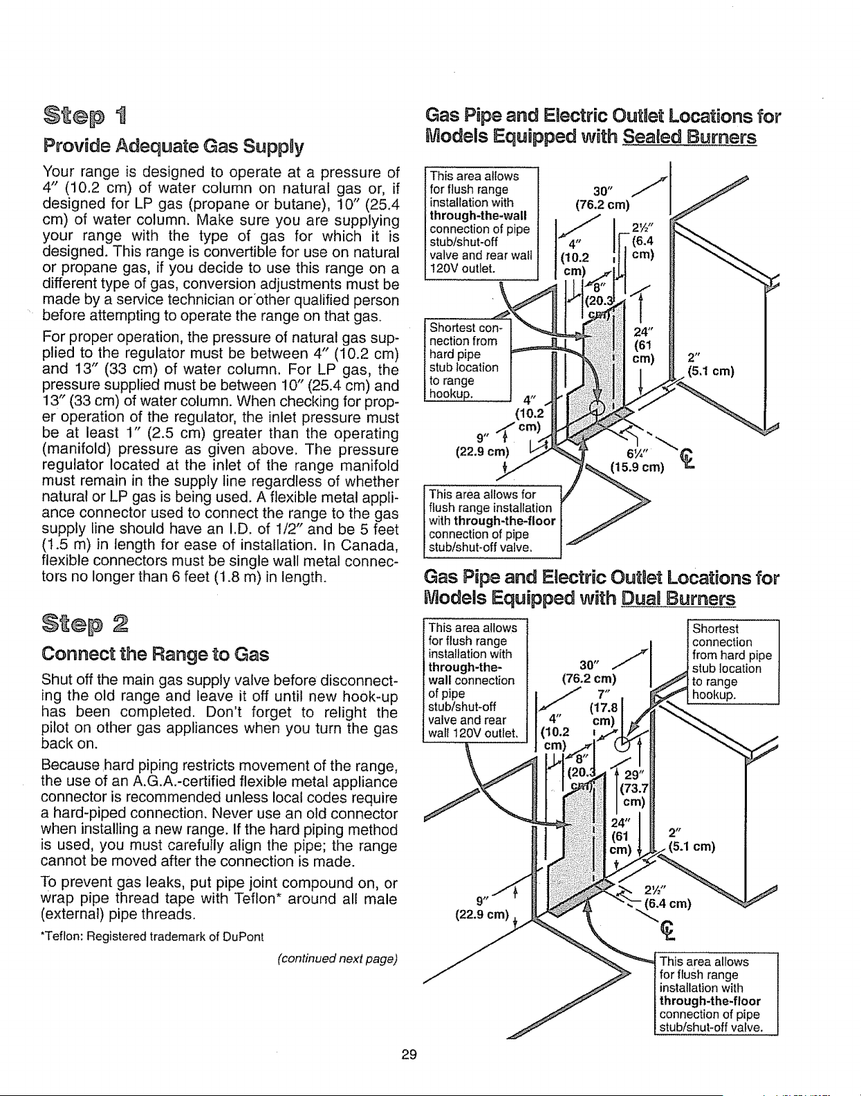
Provide Adequate Gas Supply
Your range is designed to operate at a pressure of
4" (10.2 cm) of water column on natural gas or, if
designed for LP gas (propane or butane), 10" (25.4
cm) of water column, Make sure you are supplying
your range with the type of gas for which it is
designed. This range is convertible for use on natural
or propane gas, if you decide to use this range on a
different type of gas, conversion adjustments must be
made by a service technician orother qualified person
before attempting to operate the range on that gas.
For proper operation, the pressure of natural gas sup-
plied to the regulator must be between 4" (10.2 cm)
and 13" (33 cm) of water column. For LP gas, the
pressure supplied must be between !0" (25.4 cm) and
13" (33 cm) of water column. When checking for prop-
er operation of the regulator, the inlet pressure must
be at least 1" (2.5 cm) greater than the operating
(manifold) pressure as given above. The pressure
regulator located at the inlet of the range manifold
must remain in the supply line regardless of whether
natural or LP gas is being used. A flexible metal appli-
ance connector used to connect the range to the gas
supply line should have an I.D. of 1/2" and be 5 feet
(1.5 m) in length for ease of installation. In Canada,
flexible connectors must be single wall metal connec-
tors no longer than 6 feet (1.8 m) in length.
2
Connect the Range to Gas
Shut off the main gas supply valve before disconnect-
ing the old range and leave it off until new hook-up
has been completed. Don't forget to relight the
pilot on other gas appliances when you turn the gas
back on.
Because hard piping restricts movement of the range,
the use of an A.G.A.-certified flexible metal appliance
connector is recommended unless local codes require
a hard-piped connection. Never use an old connector
when installing a new range. If the hard piping method
is used, you must carefully align the pipe; the range
cannot be moved after the connection is made.
To prevent gas leaks, put pipe joint compound on, or
wrap pipe thread tape with Teflon* around all male
(external) pipe threads.
*Teflon: Registered trademark of DuPont
(continued next page)
Gas Pipe and Electric Outlet Locations for
Models Equipped with Seat_edBurners
This area allows
for flush range 30"
installation with (76.2 cm)
through-the-wall , _i" , ,
connection of pipe I .- f I i_
stub/shut-off t_4 " IF .4
valve and rear wall I (10.2 Ijl I nl
t20V outlet. I cm) ,,._1_
122 eoo F . 2"
I_%_: ..... I . (s.1era)
(10.2 "
flush range installation l
with through4he41oor I
connection of pipe I
stub/shut-off valve, I M
¢
Gas Pipe and Electric OutBet Locations for
Models Equipped with IDuamBurners
3(} 'r
(76.2 cm)
(17.8
om
i
Shortest
connection
from hard pipe
stub location
to range
hoo _up
This area allows
for flush range
installation with
through-the-
wall connection
of pipe
stublshut-off
valve and rear
wall 120V outlet.
\
g_
(22.9 cm)
2½"
'(6.4 cm)
This area allows
for flush range
installation with
through-the-floor
connection of pipe
stub/shut-off valve.
29
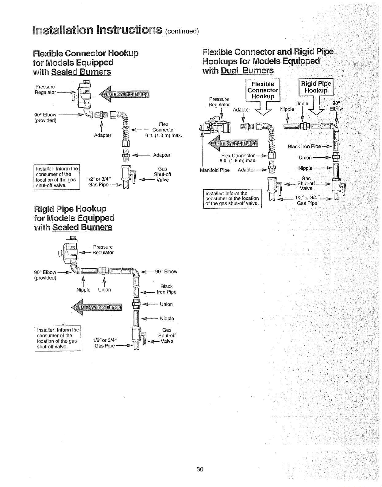
nsta ation nstruct6ons (continued)
FUexibDeConnector Hookup
for Models Equipped
with Sealed Burners
Pressure _ __
Regulator
/ _ _ Connector
Adapter _l 6 ft, (t .8 m) max,
LLJJ
@ _------ Adapler
Installer: Inform the _L. Gas
consumer of the LJ_ ! Shut-off
location of the gas 1/2"or 3/4" _ Va}ve
Lshut-off valve. Gas Pipe -"€_L_" '_
Rigid Pipe Hookup
for ModeUs Equipped
with SeaUed Burners
._ Pressure
-_--- Regulator
_0"Elbow--_ _ _ __--_'_ _ 90°Elbow
,icte Ur,'ioo '[j- __ Black
Iron Pipe
,_---- Nipple
Installer: Inform the '[- ]L, Gas
consumer of the I :|_itl Shut-off
location of the gas t/2"or 3!4" _ ltl _ Valve
shut-off valve. Gas Pipe _ L,_ "_
Flexible
Connector
Pressure Hookup
Regulator
Adapter
/_[ Flex Conneclor
| _,, (1.a,,,)max.
Manifold Pipe Adapter--;_,-_
installer: inform the
consumer of the location
of the gas shut-off valve.
Union
Nipple
Black Iron Pipe
Union _
Nipple
__._ Gas
Shul-off ..__...1_i
Valve
Gas Pipe
3O
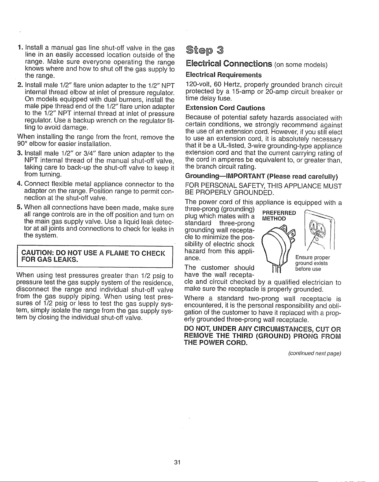
1. Install a manual gas line shut-off valve in the gas
line in an easily accessed location outside of the
range. Make sure everyone operating the range
knows where and how to shut off the gas supply to
the range.
2. Install male 1/2" flare union adapter to tile 1/2" NPT
internal thread elbow at inlet of pressure regulator.
On models equipped with dual burners, install the
male pipe thread end of the I/2" flare union adapter
to the 1/2" NPT internal thread at inlet of pressure
regulator. Use a backup wrench on the regulator fit-
ting to avoid damage.
When installing the range from the front, remove the
90 ° elbow for easier installation.
3. Install male 1/2" or 3/4" flare union adapter to the
NPT internal thread of the manual shut-off Valve,
taking care to back-up the shut-off valve to keep it
from turning.
4. Connect flexible metal appliance connector to the
adapter on the range. Position range to permit con-
nection at the shut-off valve.
5, When all connections have been made, make sure
all range controls are in the off position and turn on
the main gas supply valve. Use a liquid leak detec-
tor at all joints and connections to check for leaks in
the system.
CAUTION: DO NOT USE A FLAIVIE TO CHECKFOR GAS LEAKS.
When using test pressures greater than 1/2 psig to
pressure test the gas supply system of the residence,
disconnect the range and individual shut-off valve
from the gas supply piping. When using test pres-
sures of I/2 psig or less to test the gas supply sys-
tem, simply isolate the range from the gas supply sys-
tem by closing the individual shut-off valve.
E ectricaB Connections (onsome models)
Electrical Requirements
120-volt, 60 Hertz, properly grounded brancll circuit
protected by a 15-amp or 20-amp circuit breaker or
time delay fuse.
Extension Cord Cautions
Because of potential safety hazards associated with
certain conditions, we strongly recommend against
the use of an extension cord. However, if you still elect
to use an extension cord, it is absolutely necessary
that it be a UL-listed, 3-wire grounding-type appliance
extension cord and that the current carrying rating of
the cord in amperes be equivalent to, or greater than,
the branch circuit rating.
Grounding--IMPORTANT (Please read carefully)
FOR PERSONAL SAFETY, THIS APPLIANCE MUST
BE PROPERLY GROUNDED.
The power cord of this appliance is equipped with a
three-prong (grounding)
plug which mates with a
standard three-prong
grounding wall recepta-
cle to minimize the pos-
sibility of electric shock
hazard from this appli-
ance.
The customer should
have the wall recepta-
PREFERRED
METHOD I_ !
Ensure proper
"_._j_,_' ground exists
Ill! before use
cle and circuit checked by a qualified electrician to
make sure the receptacle is properly grounded,
Where a standard two-prong wall receptacle is
encountered, it is the personal responsibility and obli-
gation of the customer to have it replaced with a prop-
erly grounded three-prong wall receptacle.
DO NOT, UNDER ANY CIRCUMSTANCES, CUT OR
REMOVE THE THIRD (GROUND) PRONG FROrTI
THE POWER CORD.
(continued next page)
31
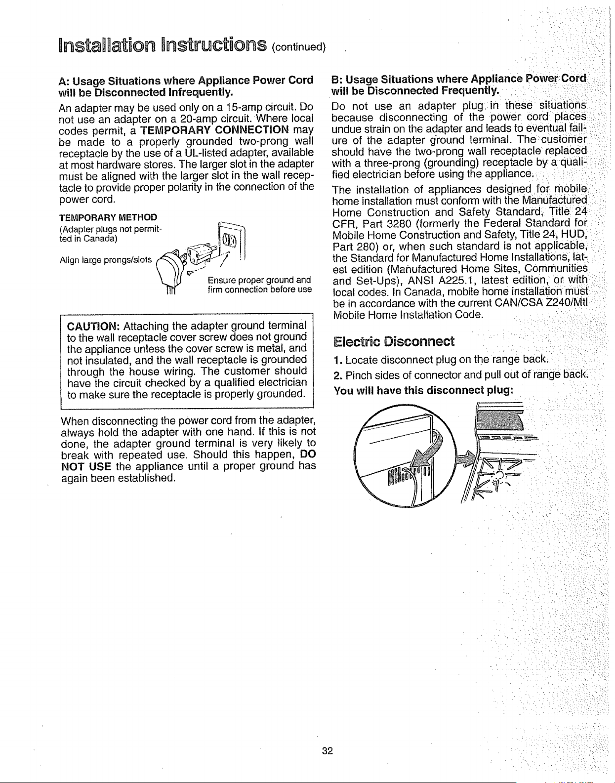
_]_sta_a'_io_ _st_'uctio_ (continued)
A: Usage Situations where Appliance Power Cord
wil! be Disconnected infrequently.
An adapter may be used only on a 15-amp circuit. Do
not use an adapter on a 20-amp circuit. Where local
codes permit, a TEMPORARY CONNECTION may
be made to a properly grounded two-prong wall
receptacle by the use of a UL-listed adapter, available
at most hardware stores. The larger slot in the adapter
must be aligned with the larger slot in the wall recep-
tacle to provide proper polarity in the connection of the
power cord.
TEMPORARY METHOD
(Adapter plugs not permit-
Align Jarge prongs/slots
(_ Ensure proper ground and
_f firm connection before use
CAUTION: Attaching the adapter ground terminal
to the wall receptacle cover screw does not ground
the appliance unless the cover screw is metal, and
not insulated, and the wall receptacle is grounded
through the house wiring, The customer should
have the circuit checked by a qualified electrician
to make sure the receptacle is properly grounded.
B: Usage Situations where Appliance Power Cord
will be Disconnected Frequently.
Do not use an adapter plug in these situations
because disconnecting of the power cord places
undue strain on the adapter and leads to eventual fail:-
ure of the adapter g'round terminal. The customer
should have the two-prong wall receptacle replaced
with a three-prong (grounding) receptacle by a quali-
fied electrician before using the appliance.
The installation of appliances designed for mobile
home installation must conform with the Manufactured
Home Construction and Safety Standard, Title 24
CFR, Part 3280 (formerly the Federal Standard for
Mobile Home Construction and Safety, Title 24, HUD,
Part 280) or, when such standard is not applicable,
the Standard for Manufactured Home Installations, lat-
est edition (Manufactured Home Sites, Communities
and Set-Ups), ANSI A225.1, latest edition, or with
local codes. In Canada, mobile home installation must
be in accordance with the current CAN/CSA Z240/Mtl
Mobile Home Installation Code.
Electric Disconnect
1. Locate disconnect plug on the range back.
2. Pinch sides of connector and pull out of range back.
You will have this disconnect plug:
When disconnecting the power cord from the adapter,
always hold the adapter with one hand. If this is not
done, the adapter ground terminal is very likely to
break with repeated use. Should this happen, DO
NOT USE the appliance until a proper ground has
again been established.
32
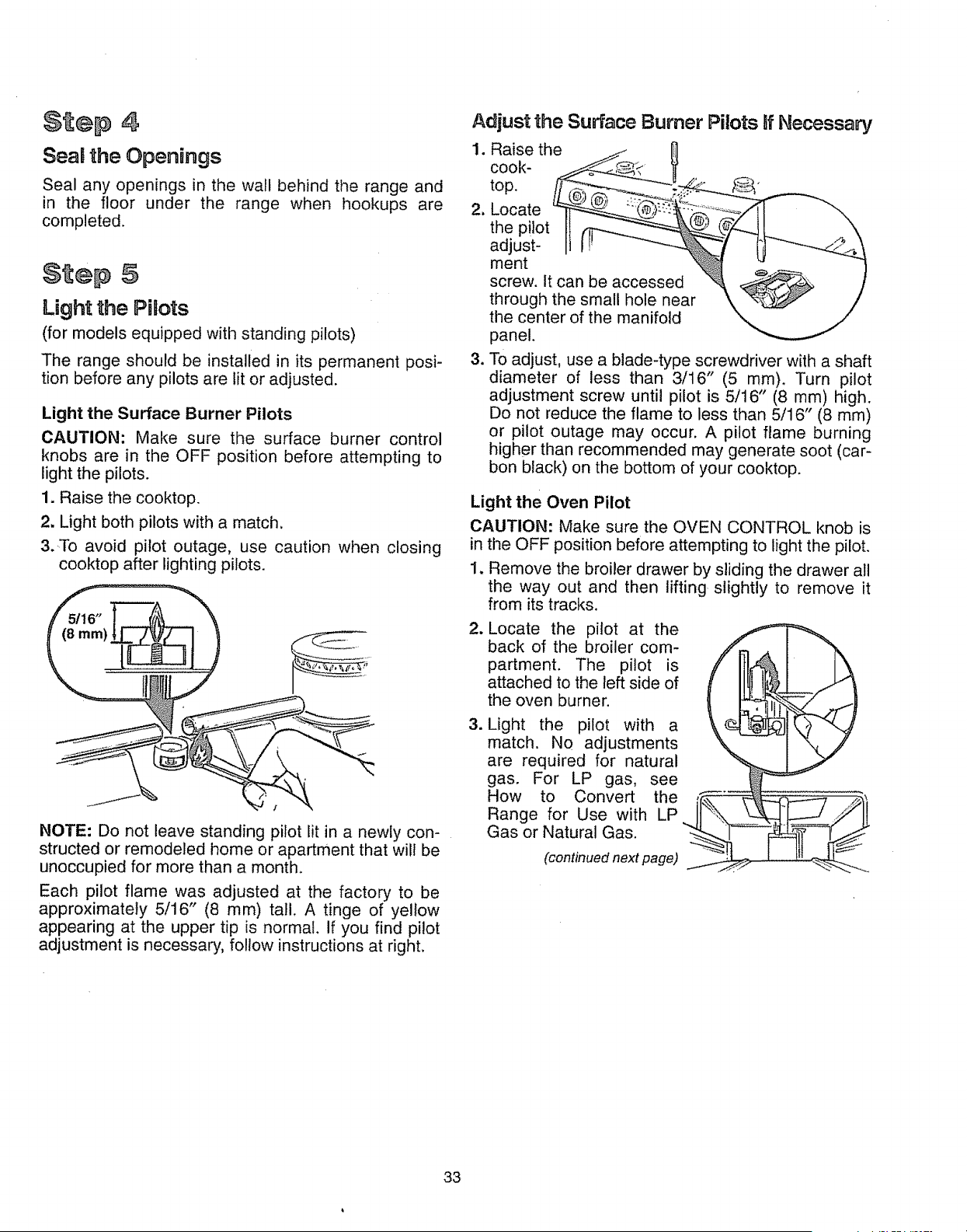
4
Seal the Openings
Seal any openings in the wall behind the range and
in the floor under the range when hookups are
completed.
Light the Pilots
(for models equipped with standing pilots)
The range should be installed in its permanent posi-
tion before any pilots are lit or adjusted.
Light the Surface Burner Pilots
CAUTION: Make sure the surface burner control
knobs are in the OFF position before attempting to
light the pilots.
1. Raise the cooktop.
2. Light both pilots with a match.
3. To avoid pilot outage, use caution when closing
cooktop after lighting pilots.
NOTE: Do not leave standing pilot lit in a newly con-
structed or remodeled home or apartment that will be
unoccupied for more than a month.
Each pilot flame was adjusted at the factory to be
approximately 5/16" (8 mm) tall. A tinge of yellow
appearing at the upper tip is normal. If you find pilot
adjustment is necessary, follow instructions at right,
Adjust the Surface Burner Pilots if Necessary
1. Raise the _I _1
cook-
top.
2, Locate ___/'1_ ""x
the pilot It ___-J L _\
adjust- It I!' _---_/' H_\
ment • _ _,_ -']
screw. It c__ __ ]
through th__ /
the center of the manifold N,. J
panel.
3. To adjust, use a blade-type screwdriver with a shaft
diameter of less than 3/16" (5 mm). Turn pilot
adjustment screw until pilot is 5/16" (8 ram) high.
Do not reduce the flame to less than 5/16" (8 ram)
or pilot outage may occur. A pilot flame burning
higher than recommended may generate soot (car-
bon black) on the bottom of your cooktop.
Light the Oven Pilot
CAUTION: Make sure the OVEN CONTROL knob is
in the OFF position before attempting to light the pilot.
1,
Remove the broiler drawer by sliding the drawer all
the way out and then lifting slightly to remove it
from its tracks.
Locate the pilot at the _ _.
back of the broiler com- _'n ,_ I -_N
partment. The pilot is f I11_1 I\
attached to the left side of _' IIq!
the oven burner. _ _EJF'_
Light the pilot with a \_l_,
match. No adjustments _,. I _ /
are required for natural _ I. _"
gas. For LP gas, see _._'_=_
How to Convert the , ,_,
Range for Use with LP
Gas or Natural Gas. __1_--I_
, _, Itl _
33
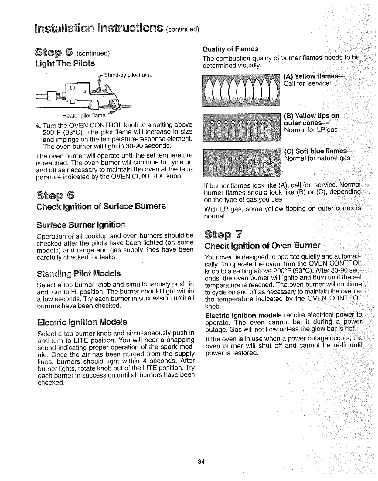
nsta ation 8nstructions (continued)
_'_e_ ,_ (continued)
Light The PHots
pilot flame
Quality of Flames
The combustion quality of burner flames needs to be
determined visually.
(A) Yellow flames--
Call for service
Heater pilot flame
4. Turn the OVEN CONTROL knob to a setting above
200°F (93°C). The pilot flame will increase in size
and impinge on the temperature-response element.
The oven burner will light in 30-90 seconds.
The oven burner will operate until the set temperature
is reached. The oven burner will continue to cycle on
and off as necessary to maintain the oven at the tem-
perature indicated by the OVEN CONTROL knob.
Check _gnition of Surface Burners
Surface Burner _gnition
Operation of all cooktop and oven burners should be
checked after the pilots have been lighted (on some
models) and range and gas supply lines have been
carefully checked for leaks.
Standing Pi_ot Models
Select a top burner knob and simultaneously push in
and turn to HI position. The burner should light within
a few seconds. Try each burner in succession until all
burners have been checked.
Enectric ignition ModeRs
Select a top burner knob and simultaneously push in
and turn to LITE position. You will hear a snapping
sound indicating proper operation of the spark mod-
ule. Once the air has been purged from the supply
lines, burners should light within 4 seconds. After
burner lights, rotate knob out of the LITE position. Try
each burner in succession until all burners have been
checked.
(B) Yellow tips on
outer cones--
Normal for LP gas.
(C) Soft blue flames--
Normal for natural gas
if burner flames look like (A), call for service. Normal
burner flames should look like (B) or (C), depending
on the type of gas you use.
With LP gas, some yellow tipping on outer cones is
normal.
Check Bgnitionof Oven Burner
Your oven is designed to operate quietly and automatF
cally. To operate the oven, turn the OVEN CONTROL
knob to a setting above 200°F (93°C). After 30-90 sect
onds, the oven burner will ignite and burn until the Set
temperature is reached. The oven burner will continue
to cycle on and off as necessary to maintain the oven at
the temperature indicated by the OVEN CONTROL
knob.
Electric ignition models require electrical power to
operate. The oven cannot be lit during a power
outage. Gas will not flow unless the glow bar is hot;
If the oven is in use when a power outage occurs, the
oven burner will shut off and cannot be re-lit untit
power is restored.
34
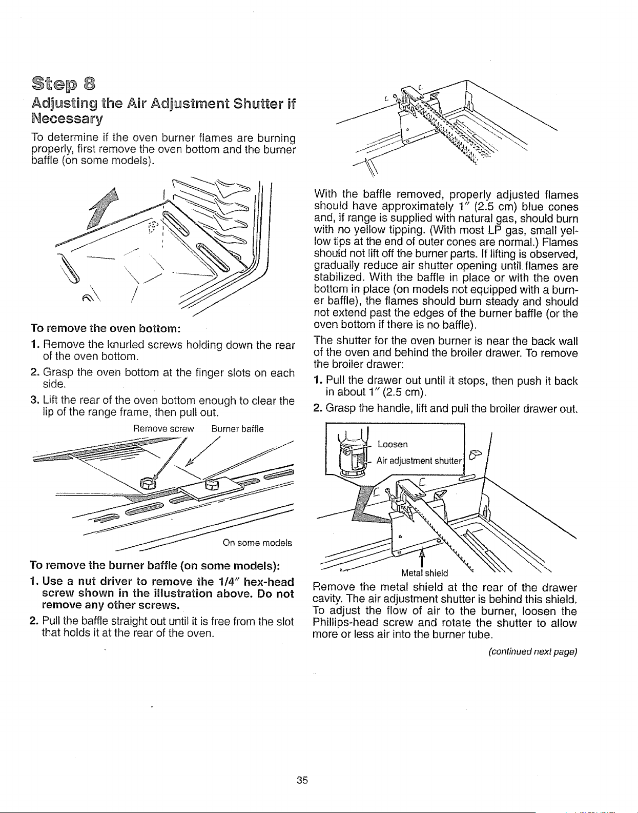
Adiusting the Air Adjustment Shutter if
Necessary
To determine if the oven burner flames are burning
properly, first remove the oven bottom and the burner
baffle (on some models).
To remove the oven bottorn:
1, Remove the knurled screws holding down the rear
of the oven bottom.
2, Grasp the oven bottom at the finger slots on each
side.
3. Lift the rear of the oven bottom enough to clear the
lip of the range frame, then pull out.
Remove screw Burner baffle
With the baffle removed, properly adjusted flames
should have approximately 1" (2.5 cm) blue cones
and, if range is supplied with natural gas, should burn
with no yellow tipping. (With most LP gas, small yel-
low tips at the end of outer cones are normal,) Flames
should not lift off the burner parts. If lifting is observed,
gradually reduce air shutter opening until flames are
stabilized. With the baffle in place or with the oven
bottom in place (on models not equipped with a burn-
er baffle), the flames should burn steady and should
not extend past the edges of the burner baffle (or the
oven bottom if there is no baffle),
The shutter for the oven burner is near the back wall
of the oven and behind the broiler drawer. To remove
the broiler drawer:
1. Pull the drawer out until it stops, then push it back
in about 1" (2.5 cm).
2. Grasp the handle, lift and pull the broiler drawer out.
Loosen
Air adjustment shutter
To remove the burner baffle (on some models):
1, Use a nut driver to remove the 114" hex-head
screw shown in the illustration above, Do not
remove any' other screws,
2, Pull the baffle straight out until it is free from the slot
that holds it at the rear of the oven.
Metal shield
Remove the metal shield at the rear of the drawer
cavity. The air adjustment shutter is behind this shield.
To adjust the flow of air to the burner, loosen the
Phillips-head screw and rotate the shutter to allow
more or less air into the burner tube.
(continued next page)
35
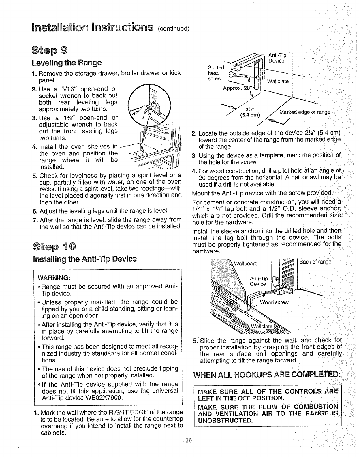
Installation Unstructions (continued)
LeveBing the Range
1. Remove the storage drawer, broiler drawer or kick
panel.
2. Use a 3/16" opemend or __
socket wrench to back out
both rear leveling legs
approximately two turns.
3, Use a 1%" open-end or
adjustable wrench to back _!i_
out the front leveling legs
two turns.
4. Install the oven shelves in
the oven and position the
range where it will be
installed.
5_
Check for levelness by placing a spirit level or a
cup, partially filled with water, on one of the oven
racks. If using a spirit level, take two readings--with
the level placed diagonally first in one direction and
then the other.
6. Adjust the leveling legs until the range is level.
7. After the range is level, slide the range away from
the wal! so that the Anti-Tip device can be installed.
82e# t @
gnstalming the Anti-Tip Device
WARNING:
o Range must be secured with an approved Anti-
Tip device.
o Unless properly installed, the range could be
tipped by you or a child standing, sitting or lean-
ing on an open door.
o After installing the Anti-Tip device, verify that it is
in place by carefully attempting to tilt the range
forward.
o This range has been designed to meet all recog,
nized industry tip standards for all normal condi-
tions.
° The use of this device does not preclude tipping
of the range when not properly installed.
• If the Anti-Tip device supplied with the range
does not fit this application, use the universal
Anti-Tip device WB02X7909.
Mark the wall where the RIGHT EDGE of the range
is to be located. Be sure to allow for the countertop
overhang if you intend to install the range next to
cabinets.
36
_ • : :v :,I_: ::
• , "i • ,:i :: iI_/:
1
.
4,
_,_ Anti-Tip I ....... ....
el Devicei
S o.ed t
head _ ! I I - _ _ : :
lll a,,0, o1
Approx. 20 ' 4._..._ i : :
7" (52Yc'm) /,"'Marked edge of
-'
Locate the outside edge of the device 2W" (5,4 cm) :i
toward the center of the range from the marked edge
of the range.
Using the device as a template, mark the position of
the hole for the screw.
For wood construction, drill a pilot hole at an angle of
20 degrees from the horizontal. A nail or awl may be
used if a drill is not available.
Mount the Anti-Tip device with the screw provided:
For cement or concrete construction, you will need a
1/4" x 1W' lag bolt and a 1/2" O.D. sleeve anchor,
which are not provided. Drill the recommended size
hole for the hardware.
Install the sleeve anchor into the drilled hole and then
install the lag bolt through the device. The bolts
must be properly tightened as recommended for the
hardware.
Wallboard
Anti-Tip
Device
Wood screw
Back of range
&Slide the range against the wall, and check for
proper installation by grasping the front edges of
the rear surface unit openings and carefully
attempting to tilt the range forward.
WHEN ALL HOOKUPS ARE COMPLETED:
MAKE SURE ALL OF THE CONTROLS: ARE
LEFT IN THE OFF POSITION.
iVIAKE SURE THE FLOW OF COMBUSTION
AND VENTILATION AIR TO THE RANGE IS
UNOBSTRUCTED.
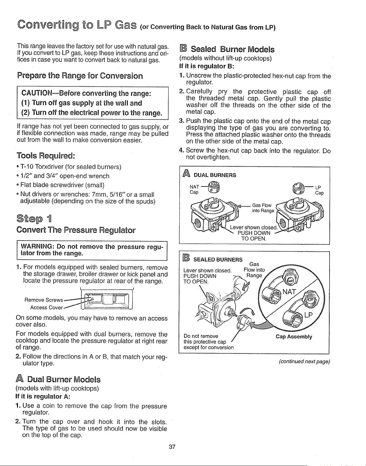
(C_o_Ve_ti_g tO L_ _S (or Converting Back to Natural Gas from LP)
This range leaves the factory set for use with natural gas.
If you convert to LP gas, keep these instructions and ori-
fices in case you want to convert back to natural gas.
Prepare the Range for Conve_'sion
CAUTiON--Before converting the range:
(1) Turn off gas supply at the wall and
(2) Turn off the electrical power to the range.
If range has not yet been connected to gas supply, or
if flexible connection was made, range may be pulled
out from the wall to make conversion easier.
TooDsRequired:
• T-IO Torxdriver (for sealed burners)
o 1/2" and 3/4" open-end wrench
o Flat blade screwdriver (small)
o Nut drivers or wrenches: 7ram, 5/16" or a small
adjustable (depending on the size of the spuds)
$2÷@ t
Convert The Pressure Reguaator
i ARNING: Do not remove the pressure regu- ]
lator from the range.
1
1. For models equipped with sealed burners, remove
the storage drawer, broiler drawer or kick panel and
locate the pressure regulator at rear of the range.
Access Cover
On some models, you may have to remove an access
cover also.
For models equipped with dual burners, remove the
cooktop and locate the pressure regulator at right rear
of range.
2. Follow the directions in A or B, that match your reg-
ulator type.
DuamBurner Models
(models with lift-up cooktops)
If it is regulator A:
1. Use a coin to remove the cap from the pressure
regulator.
2. Turn the cap over and hook it into the slots.
The type of gas to be used should now be visible
on the top of the cap.
37
Sealed Burner Models
(models without lift-up cooktops)
if it is regulator B:
1. Unscrew the plastic-protected hex-nut cap from the
regulator.
2. Carefully pry the protective plastic cap off
the threaded metal cap. Gently pull the plastic
washer off the threads on the other side of the
metal cap.
3, Push the plastic cap onto the end of the metal cap
displaying the type of gas you are converting to.
Press the attached plastic washer onto the threads
on the other side of the metal cap.
4. Screw the hex-nut cap back into the regulator. Do
not overtighten.
SEALED BURNERS
Levershownclosed.
PUSH DOWN
TO OPEN.
Gas
Flow
Do not remove Cap Assembly
this protective cap
except for conversion
(continued next page)
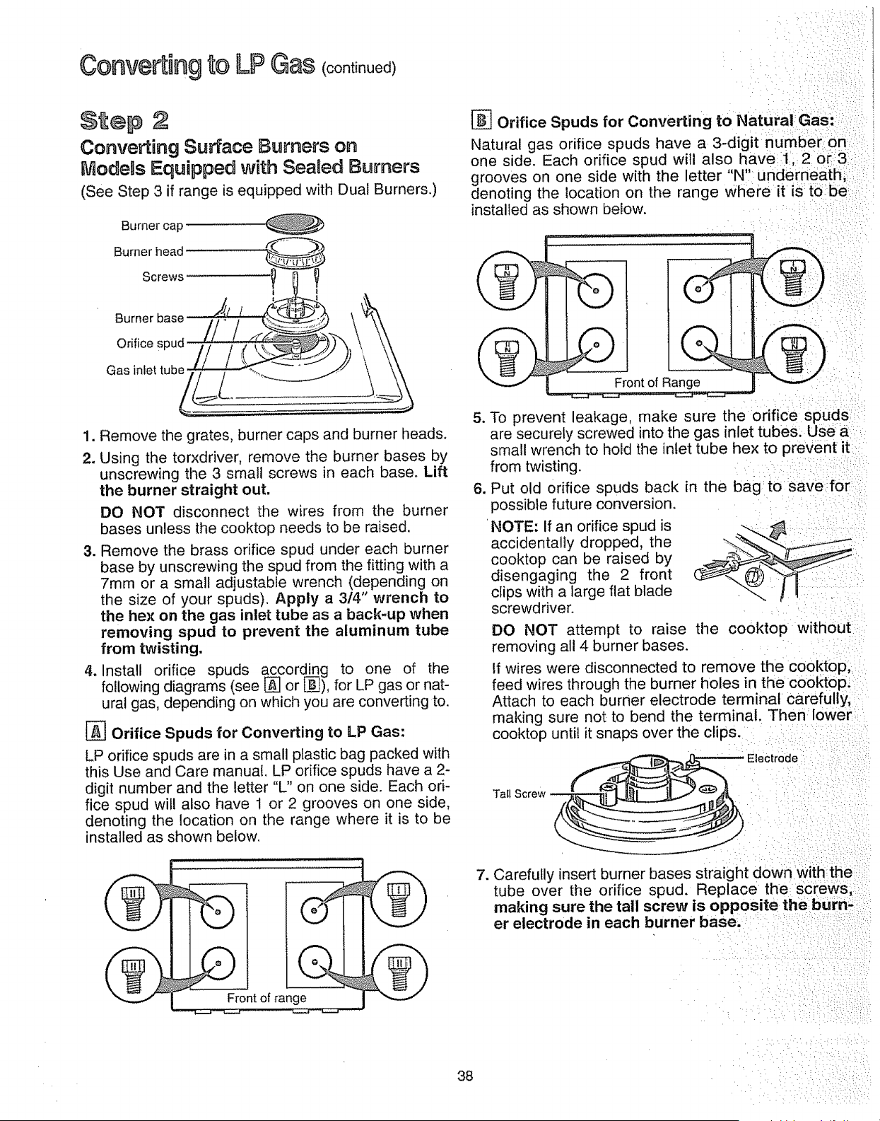
¢onve ing to LP Gas (ooot oued)
Converting Surface Burners on
Models Equipped with Sea ed Burners
(See Step 3 if range is equipped with Dual Burners.)
Burner cap
Burner head
Screws
Burner base
Orifice spud
1. Remove the grates, burner caps and burner heads.
2. Using the torxdriver, remove the burner bases by
unscrewing the 3 small screws in each base. Lift
the burner straight out.
DO NOT disconnect the wires from the burner
bases unless the cooktop needs to be raised.
3. Remove the brass orifice spud under each burner
base by unscrewing the spud from the fitting with a
7mm or a small adjustable wrench (depending on
the size of your spuds). Apply a 314" wrench to
the hex on the gas inlet tube as a back-up when
removing spud to prevent the aluminum tube
from twisting.
4. Install orifice spuds according to one of the
following diagrams (see [] or []), for LP gas or nat-
ural gas, depending on which you are converting to.
[_ Orifice Spuds for Converting to LP Gas:
LP orifice spuds are in a small plastic bag packed with
this Use and Care manual. LP orifice spuds have a 2-
digit number and the letter "L" on one side. Each ori-
fice spud will also have 1 or 2 grooves on one side,
denoting the location on the range where it is to be
installed as shown below.
: :::: ::L::i_ !i:::;!i ¸
Orifice Spuds for Converting to Natural
Natural gas orifice spuds have a 3-digit:
one side. Each orifice spud will also have::1:;: 2 o_::3::::::::::
grooves on one side with the letter
denoting the location on the range Where it is
installed as shown below.
5.
6.
Front of Range
To prevent leakage, make sure the orifice spuds
are securely screwed into the gas inlet tubes. Use a
small wrench to hold the inlet tube hex to prevent it
from twisting.
Put old orifice spuds back in the bag to save for
possible future conversion.
NOTE: If an orifice spud is _-_..
accidentally dropped, the --_..'_%____
cooktop can be raised by _
disengaging the 2 front
clips with a large flat blade
screwdriver.
DO NOT attempt to raise the cooktop without
removing all 4 burner bases.
If wires were disconnected to remove the cooktop,
feed wires through the burner holes in the cooktop:
Attach to each burner electrode terminal carefullyi
making sure not to bend the terminal. Then lower
cooktop until it snaps over the clips.
Electrode
Tail Screw --
Front of range
7. Carefully insert burner bases straight down with:the
tube over the orifice spud. Replace the screws,
making sure the tall screw is opposite the burnL
er electrode in each burner base;
38
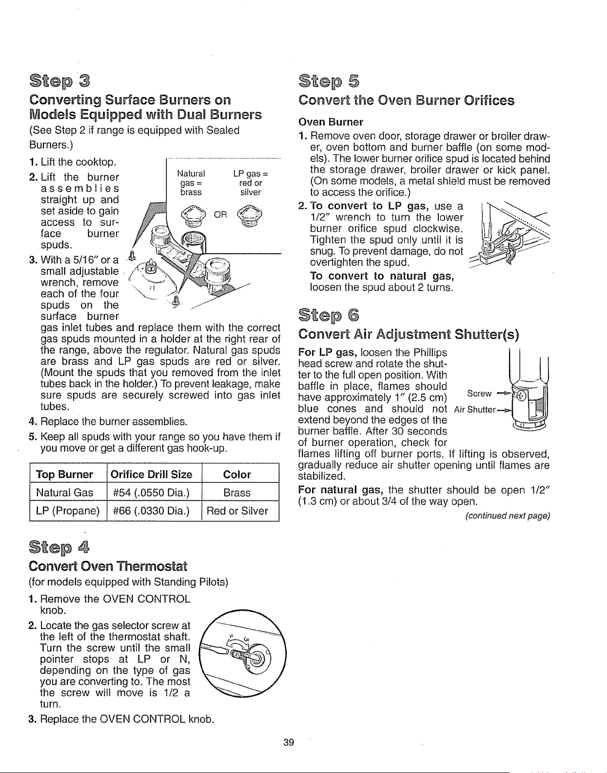
Converting Surface Burners on
ModeRs Equipped with Duan Burners
(See Step 2 if range is equipped with Sealed
Burners.)
1. Lift the cooktop.
2. Lift the burner
assemblies
straight up and
set aside to gain
access to sur-
face burner
spuds.
3. With a 5/i 6" or a
small adjustable
wrench, remove
each of the four
spuds on the
surface burner
Natural LP gas =
gas = red or
brass silver
©OR ......
,,&
"'.2.....
gas inlet tubes and replace them with the correct
gas spuds mounted in a holder at the right rear of
the range, above the regulator. Natural gas spuds
are brass and LP gas spuds are red or silver.
(Mount the spuds that you removed from the inlet
tubes back in the holder.) To prevent leakage, make
sure spuds are securely screwed into gas inlet
tubes.
4. Replace the burner assemblies.
5. Keep all spuds with your range so you have them if
you move or get a different gas hook-up.
Top Burner Orifice Drill Size Color
Natural Gas #54 (.0550 Dia.) Brass
LP (Propane) #66 (.0330 Dia.) Red or Silver
Convert the Oven Burner Orifices
Oven Burner
1. Remove oven door, storage drawer or broiler draw-
er, oven bottom and burner baffle (on some mod-
els). The lower burner orifice spud is located behind
the storage drawer, broiler drawer or kick panel.
(On some models, a metal shield must be removed
to access the orifice,)
2. To convert to LP gas, use a I q"_,,_
1/2" wrench to turn the lower
burner orifice spud clockwise.
Tighten the spud only until it is
snug. To prevent damage, do not
overtighten the spud.
To convert to natural gas,
loosen the spud about 2 turns.
@
Convert Air Adjustment Shutter(s)
For LP gas, loosen the Phillips
head screw and rotate the shut-
ter to the full open position. With
baffle in place, flames should
have approximately 1" (2.5 cm)
blue cones and should not
extend beyond the edges of the
burner baffle. After 30 seconds
of burner operation, check for
Screw --_,-_
Air Shutter_
flames lifting off burner ports. If lifting is observed,
gradually reduce air shutter opening until flames are
stabilized.
For natural gas, the shutter should be open 1/2"
(1.3 cm) or about 3/4 of the way open.
(continued next page)
Convert Oven Thermostat
(for models equipped with Standing Pilots)
1. Remove the OVEN CONTROL
knob.
2. Locate the gas selector screw at
the left of the thermostat shaft.
Turn the screw until the small
pointer stops at LP or N,
depending on the type of gas
you are converting to. The most
the screw will move is 1/2 a
turn.
3, Replace the OVEN CONTROL knob.
39
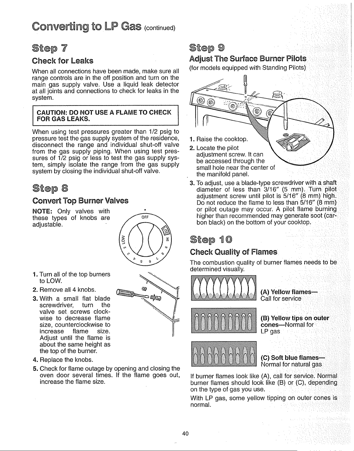
ConveAHngto LP Gas (continued)
Check for Leaks
When all connections have been made, make sure all
range controls are in the off position and turn on the
main gas supply valve. Use a liquid leak detector
at all joints and connections to check for leaks in the
system.
I CAUTtON: DO NOT USE A FLAME TO CHECK |
|
FOR GAS LEAKS.
1
When using test pressures greater than 1/2 psig to
pressure test the gas supply system of the residence,
disconnect the range and individual shut-off valve
from the gas supply piping. When using test pres-
sures of 1/2 psig or less to test the gas supply sys-
tem, simply isolate the range from the gas supply
system by closing the individual shut-off valve.
Convert Top Burner Valves
NOTE: Only valves with
these types of knobs are
adjustable.
1. Turn all of the top burners
to LOW.
2. Remove all 4 knobs.
3, With a small flat blade
screwdriver, turn the
valve set, screws clock-
wise to decrease flame
size, counterclockwise to
increase flame size.
Adjust until the flame is
about the same height as
the top of the burner.
4. Replace the knobs.
5. Check for flame outage by opening and closing the
oven door several times. If the flame goes out,
increase the flame size.
Adjust The Surface Burner Piiots :,
(for mode s equ pped w th Standing Pilots):: :;
1. Raise the cooktop.
2. Locate the pilot
adjustment screw. It can i
be accessed through the
small hole near the center of
the manifold panel.
3. To adjust, use a blade-type screwdriver with a shaft
diameter of less than 3/16 (5 ram). Turn •pilot ::
adjustment screw until pilot is 5/i6 _' (8 mm) high.
Do not reduce the flame to less than 5/I6" (8 mm)
or pilot outage may occur. A pilot flame burning
higher than recommended may generate soot (car-
bon black) on the bottom of your cooktop.
Check Quality of Flames
The combustion quality of burner flames needs to be
determined visually.
(A) Yellow flames--
Call for service
(B) Yellow tips on outer
conesmNormal for
LP gas
(C) Soft blue flames--
Normal for natural gas
If burner flames look like (A), call for service: Normal
burner flames should look like (B) or (C), depending
on the type of gas you use,
With LP gas, some yellow tipping on outer cones is
normal.
40
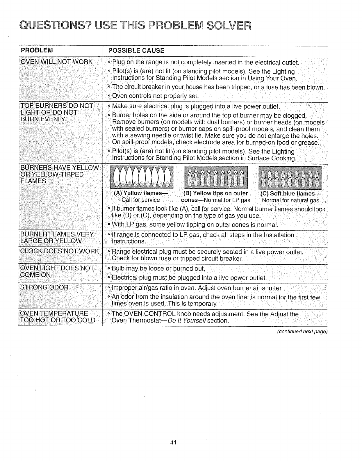
QUESTIONS? USE TH S PROBLEM SOLVER
PROBLEM
I;O_EN::!WiLL:NOT WORK
BURNERFLAMES:VERY
:::EARGE:OR:!¥ELLOW :: :
::GEOCKDOESNOT WORK
:i
_:::OVENLIGHT DOES NOT
_G_ME:!::QN !::::i:!{::
S_RONG ODOR
{OVENTEMPERATURE
I:TO0 HOT: O:R TOOCOLD
POSSIBLE CAUSE
,' Plug on.the range is not completely inserted in the electrical outlet.
opilot(s) is (are) not lit (on standing pilot models). See the Lighting
Instructions for Standing Pilot Models section in Using Your Oven.
,, The circuit breaker in your house tlas been tripped, or a fuse has been blown.
o:Oven controls not properly set.
Make sure electrical plug is plugged into a live power outlet,
°Burner holes on the side or around the top of burner may beclogged.
Remove burners (on models with dual burners) or burner heads (on models
with sealed burners) or burner caps on spill-proof models, and clean them
with a sewing needle or twist tie. Make sure you do not enlarge the holes.
On spill-proof models, check electrode area for burned-on food or grease.
o:Pilot(s) is (are) not lit (on standing pilot models). See the Lighting
Instructions for Standing Pilot Models section in Surface Cooking.
(A) Yellow flames--
Call for service
(B) Yellow tips on outer
coneswNormal for LP gas
o If burner flames look like (A), call for service. Normal burner flames should look
like (B) or (C), depending on the type of gas you use.
oWith LP gas, some ye!low tipping on outer cones is normal.
o !f range is connected to LP gas, ctleck all steps in tile Installation
Instructions.
(C) Soft blue flames.-
Normal for natural gas
o:Range electrical p!ug must be securely seated in a live power outlet.
Check for blown fuse or tripped circuit breaker.
_Bulb may be loose or burned out.
oElectrical plug must be plugged into a live power outlet.
, :Improper air/gas ratio in oven. Adjust oven burner air shutter.
o An odor from the insulation around the oven liner is normal for the first few
times oven is used. This is temporary,
,, The OVEN CONTROL knob needs adjustment. See the Adjust the
Oven Thermostat_Do tt Yourseff section.
(continued next page)
41
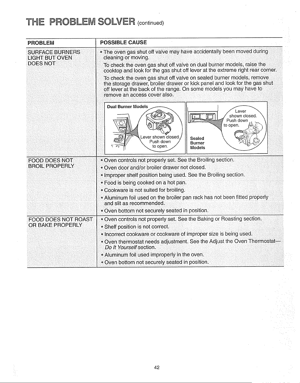
THE PROBLEM SOLVER (continued)
PROBLEM POSSIBLE CAUSE
i
i:::controls:fi8
::ith e:B r0iii ng :secti_ n !::i::::: i
:or: R0asting sectioni:::
42

NOTES
43
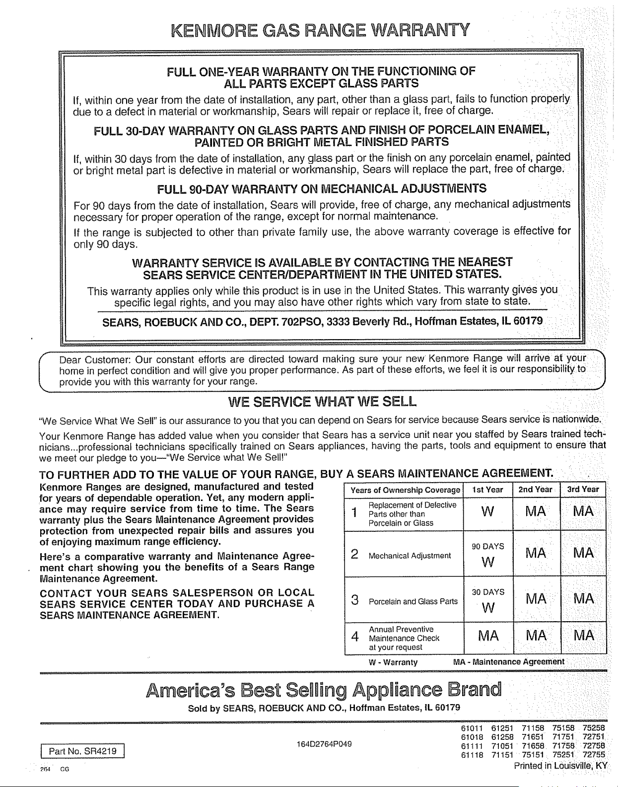
KENMORE GAS
RANGE WARRANTY
-, ,/i, _ i ,: • :
'_ :::: : :i:::: i
: : i _:II _ " i
FULL ONE-YEAR WARRANTY ON THE FUNCTIONgNG OF
ALL PARTS EXCEPT GLASS PARTS ..... i
ii
If, within one year from the date of installation, any part, other than a glass part, fails to function properly
due to a defect in material or workmanship, Sears welt repair or replace it, free of charge.
FULL 30-DAY WARRANTY ON GLASS PARTS AND FINISH OF PORCELAIN ENAMEL,
PAINTED OR IBRIGHT METAL FINISHED PARTS
If, within 30 days from the date of installation, any glass part or the finish on any porcelain enamel, painted
or bright metal part is defective in material or workmanship, Sears will replace the part, free of charge.
FULL 90-DAY WARRANTY ON MECHANICAL ADJUSTMENTS i
For 90 days from the date of installation, Sears will provide, free of charge, any mechanical adjustments
necessary for proper operation of the range, except for normal ma_tenance.
If the range is subjected to other than private family use, the above warranty coverage is effective for
only 90 days.
WARRANTY SERVICE RSAVAILABLE BY CONTACTING THE NEAREST
SEARS SERVICE CENTER/DEPARTMENT IN THE UNITED STATES.
This warranty applies only while this product is in use in the United States. This warranty gives you
specific legal rights, and you may also have other rights which vary from state to state.
SEARS, ROEBUCK AND CO., DEPT. 702PSO, 3333 Beverly Rd., Hoffman Estates, IL 60179
Dear Customer: Our constant efforts are directed toward making sure your new Kenmore Range will arrive at your "_
home in perfect condition and wit! give you proper performance. As part of these efforts, we feet it is our responsibility to
J
provide you with this warranty for your range. J
WE SERVICE WHAT WE SELL
"We Service What We Sell" is our assurance to you that you can depend on Sears for service because Sears service is nationwide.
Your Kenmore Range has added value when you consider that Sears has a service unit near you staffed by Sears trained tech,
nicians...professionat technicians specifically trained on Sears appliances, having the parts, tools and equipment to ensure that
we meet our pledge to you--"We Service what We Sell!"
TO FURTHER ADD TO THE VALUE OF YOUR RANGE,
Kenmore Ranges are designed, manufactured and tested
for years of dependable operation. Yet, any modern appli-
ance may require service from time to time. The Sears
warranty plus the Sears Maintenance Agreement provides
protection from unexpected repair bills and assures you
of enjoying maximum range efficiency.
Here's a comparative warranty and Maintenance Agree-
ment chart showing you the benefits of a Sears Range
Maintenance Agreement.
CONTACT YOUR SEARS SALESPERSON OR LOCAL
SEARS SERVICE CENTER TODAY AND PURCHASE A
SEARS MAINTENANCE AGREEMENT.
3rd Year
Replacement of Defective
1 Partsotherthan W :_ MA _ MA
Porcelain orGlass " i: :: :i
90DAYS MA MA
2 Mechanical Adjustment W
= ....
30DAYS MA _ MA
3 Porcelain and Glass Parts W
4 i
MA - Maintenance Agreement
, r .......
BUY A SEARS MAINTENANCE AGREEMENT.
Years of Ownership Coverage 1st Year 2nd Year
Annual P_eventive
Maintenance Check
at your request
W - Warranty
t Part No, SR4219 1
?64 CG
Am÷rica's Best SeUling App ianc÷ Brand
Sold by SEARS, ROEBUCK AND CO., Hoffman Estates, IL 60179
164D2764P049
. . • ............ n ....
61011 61251 71158 75158 75258
61018 61258 71651 71751 72751
61111 71051 71658 71758 72758
61118 71151 75151 75251 72755
Printed in Louisville, KY
Aparalo anli°volcaduras ............................. 2, 3, 29, 38
Instrucciones importantes de seguridad ............. 2-6
FI_-._"_£'_[_@_O_._ .......................................... 28--43
Ajuste del aire ............................................................ 37
Conversi6n a gas LP (Propano) ........................... 39-43
Conexiones el@ctricas .......................................... 33,34
DimEnsiones y espacios .......................................... 28
Instalaci6n del aparato anti-volcaduras .................. 38
Localizaci6n de la tuberia de gas
y de la toma de corriente ............................... 31,32
Uoe@ V ©UDD_@©
Asado al fuego directofGuia ............................... 19, 20
Asar at hornolGuia .............................................. 17, 18
Caracteristicas de su estufa ....................................... 7
Cocinar en la parte superior ................................ 8-11
Comparacion de cubiertas ......................................... 8
Cuidado y limpieza ............................................. 21-27
Hornear ................................................................. 14, 15
Reloj e indicador de tiempo ...................................... 11
Uso de su homo ................................................. 12, 13
aeEBVD©D@
Ajuste del termostato del horno .............................. 16
Guia para resolver problemas ............................ 44, 45
@AilAIITIA ........................................................48
MODELOS_61011 >.-71151 "I-71758
-,L-61018 ,"" 71158 _c75251
_,.61111 F-71651 _ 75258
)'-61"i18 -,_71658 _-72751
61251 _'75151 "!-72758
-_.61258 _ _72755
-_,71051 y 71751
164D2764P049
SR4219
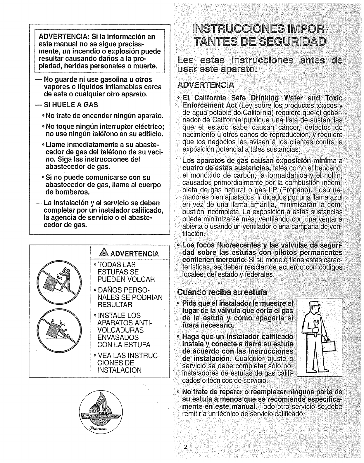
ADVERTENCIA: Si la informaci6n en
este manual no se sigue precisa-
mente, un incendio o expiosibn puede
resultar causando dafios a la pro-
piedad, heridas personales o muerte.
w No guarde ni use gasolina u otros
vapores o liquidos inflamables cerca
de este o cualquier otro aparato.
SI HUELE A GAS
oNo trate de encender ning_n aparato.
oNo toque ningen interruptor el_ctrico;
no use ning_n tei_fono en su edificio.
Llame inmediatamente a su abaste-
cedor de gas del tel_fono de su veci-
no. Siga las instrucciones del
abastecedor de gas.
oSi no puede comunicarse con su
abastecedor de gas, Ilame al cuerpo
de bomberos.
La instalaci6n y el servicio se deben
completar por un instalador calificado,
la agencia de servicio o el abaste-
cedor de gas.
ADVERTENClA
=TODAS LAS
ESTUFAS SE
PUEDEN VOLCAR
o DANOS PERSO-
NALES SE PODRIAN
RESULTAR
INSTALE LOS
APARATOS ANTI-
VOLCADURAS
ENVASADOS
CON LA ESTUFA
VEA LAS INSTRUC-
CLONES DE
INSTALACION
: Enforcement
i: cauSad0s
.........::::::::::::::::::::::::::
serviclo
cados o t_cnicos deservic
o No trate de re
mente en
remitir a un t_cnico de servmcto
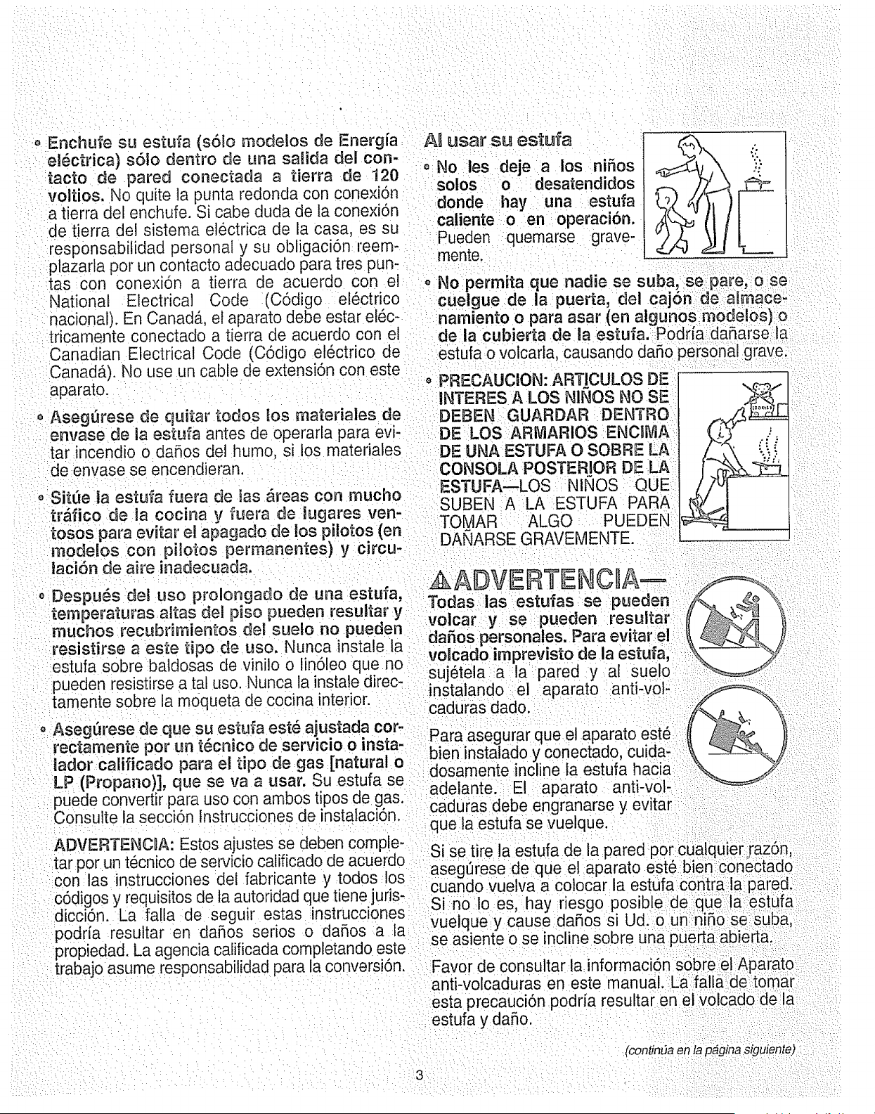
Enchufe su estu_a (s61o modeios de Energfa
et6ctrica) s6io dentro de una satida del con-
tacto de pared conectada a tierra de 120
voltios. No quite la punta redondacon conexi6n
a tierra del enchufe. Sicabe duda de la conexi6n
de tierra del sistema eiectrica de la casa, es su
responsabilidad personal y su obligaci6n reem-
plazarla por un contacto adecuado para tres pun-
tas con conexion a tierra de acuerdo con el
National Electrical Code (C6digo el6ctrico
nacional). En CanadA, et aparato debe estar el_c-
tricamente conectado a tierra de acuerdo con el
Canadian Electrical Code (C6digo el6ctrico de
CanadA). No use un cable de extensi6n con este
aparato.
o Aseg_rese de quitar todos Ios raateriales de
envase de la estufa antes de operarfa para evi-
tar incendio o daSos del humo, si los materiales
de envase se encendieran.
Al usar su estufa
o No les deje a los niSos
solos o desatendidos
donde hay una estufa
caliente o en operaci6n.
Pueden quemarse grave-
mente.
,, Sit_e la estufa t'uera de las Areas con mucho
tr_fico de _a cocina y fuera de lugares ven-
tosos para evitar el apagado de los pitoto.s (en
rnodelos con pitotos perraanentes) y cJrcu-
taci6n de aire inadecuada,
o Despu_s del uso prolongado de una estufa,
ternperaturas altas del piso pueden resuBtar y
rnuchos recubrirnientos del sueto no pueden
resistirse a este tipo de uso. Nunca instale la
estufa sobre baldosas de vinilo o linoleo queno
pueden resistirse a tal uso. Nunca la instale direc-
tamente sobre la moqueta de cocina interior.
o No permita que nadie se suba, se:::pare,:o se
cuelguede la puerta, del caj6n:dealrnace_
narniento o para asar (en aigunosrnodel0s} o
de la cubierta de la estufa. PoddadaSarSe la
estufa o volcarla, causando daSo personal grave.
o PRECAUCION: AR_CULOS DE
INTERES A LOS NINOS NO SE
DEBEN GUARDAR DENTRO
DE ,LOS ARIViARIOS :ENCBIVIA
DE UNA ESTUFA O SOBRE LA
CONSOLA POSTERIOR DE LA
ESTUFA--LOS :NINOS QUE
SUBEN A LA ESTUFA PARA
TOMAR ALGO PUEDEN
DAi_ARSE GRAVEMENTE.
ADVERTENCDA
Todas ias estufas:se pueden
volcar y se pueden resultar
daSos personales, Para evitar el
volcadoirnprevisto de la estufa,
sujetela a la pared y al suelo
instalando iel aparato anti-vol-
caduras dado.
Para asegurar queel aparato est_
bien instalado y conectado, cuida'
dosamente incline la estufa hacia
q
!
i
Asegt_rese de que su estufa est_ ajustada cor-
rectarnente pot un t_cnico de serwcio o insta-
lador calificado para el tipo de gas [natural o
LP (Propano)], que se vaa usar. Su estufa se adelante El a"arato anti vol
puede convertir para uso con ambos tipos degas. ,,=a,r_ _,_ _n_r_;<_<_ ,, _ilt_
Coosu tesecc 6 nst'ucco esde : e] es [ase';Yuei&ue'
q q .
ADVERTENCIA: Estos ajustes se deben comp!e- Si se tire la estufa de la pared por:cualquier raz6n,
tar por un tecnico de servicio calificado de acuerdo asegerese de que el aparato este bien coneCtado
con las instrucciones de! fabricante y todos los ....
c6di,_os ,, renuisitos de la autoridad ,_uet ene _urs cuando vuelva a colocar la estufa contra: la: pared:
dicc_n._'L_a_alfa de seguir estas'_instrucci_nes _ie_qi!°yeSc_uha_
podria resultar en dafios serios o daBos a la se asient[_ o se incline sobre u'napuerta abiertai:i ii
propiedad. La agencia calificada completando este
trabajo asume responsabilidad para Ia conversi6n. Favor de consultar a informaci6n sobre el:Aparato
anti-volcadurasen este manua. La faila de :t0mar
esta precauci6n podna resultar en el V01cado de]a
estufa y dafio.
(continE_aen la i_agina isiguiente)
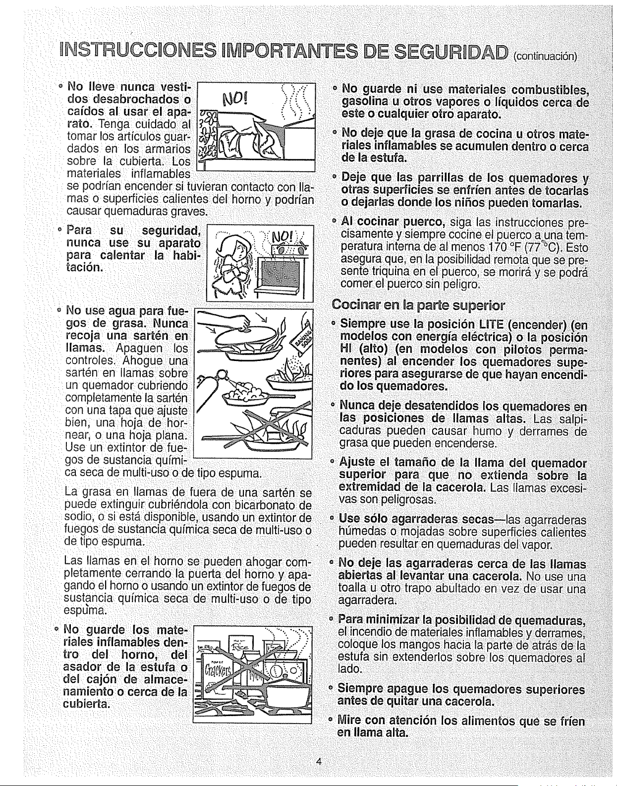
II ISTR UOC
No Ileve: nunca::vesti-
dos desabrochad0s o
caidos al usar:el apa,
taro. Tenga cuidado:at
tomar !osartfculos guar_
dados en 10s armarios
sobre la cubierta.:: Los
materiales inflamables
se podrian encender si tuvieran
mas o superficies:catientes
causar quemaduras graves.
o ::..\
taci6n.
No use agua para fue-
gos de grasa.: Nunca
recoja una sart4n en
lamas.: Apaguen ::los
controles. Ahogue una
sart_n en llamas sobre
un quemador cubriendo
completamente la sart_n
con una tapa que ajuste
bien, una hoja de hor_
neari o una hoja planai
Use un extintor deii:fue:
gos de st
ca seca de multi
|
La grasa en
luede extingUir: cubri6ndola: con
odio; o si est,_disp0nible; usando un extint0_ de>i:
fuegos de sustanciaqu!mica seca demu ti
de tipo espuma:
Las llamas enel:horno se
pletamente cerra u(
g_
sustancia q
espuma.
o No guarde::los mate_
dales inflamablesden.i
ii_ :_ttO :q
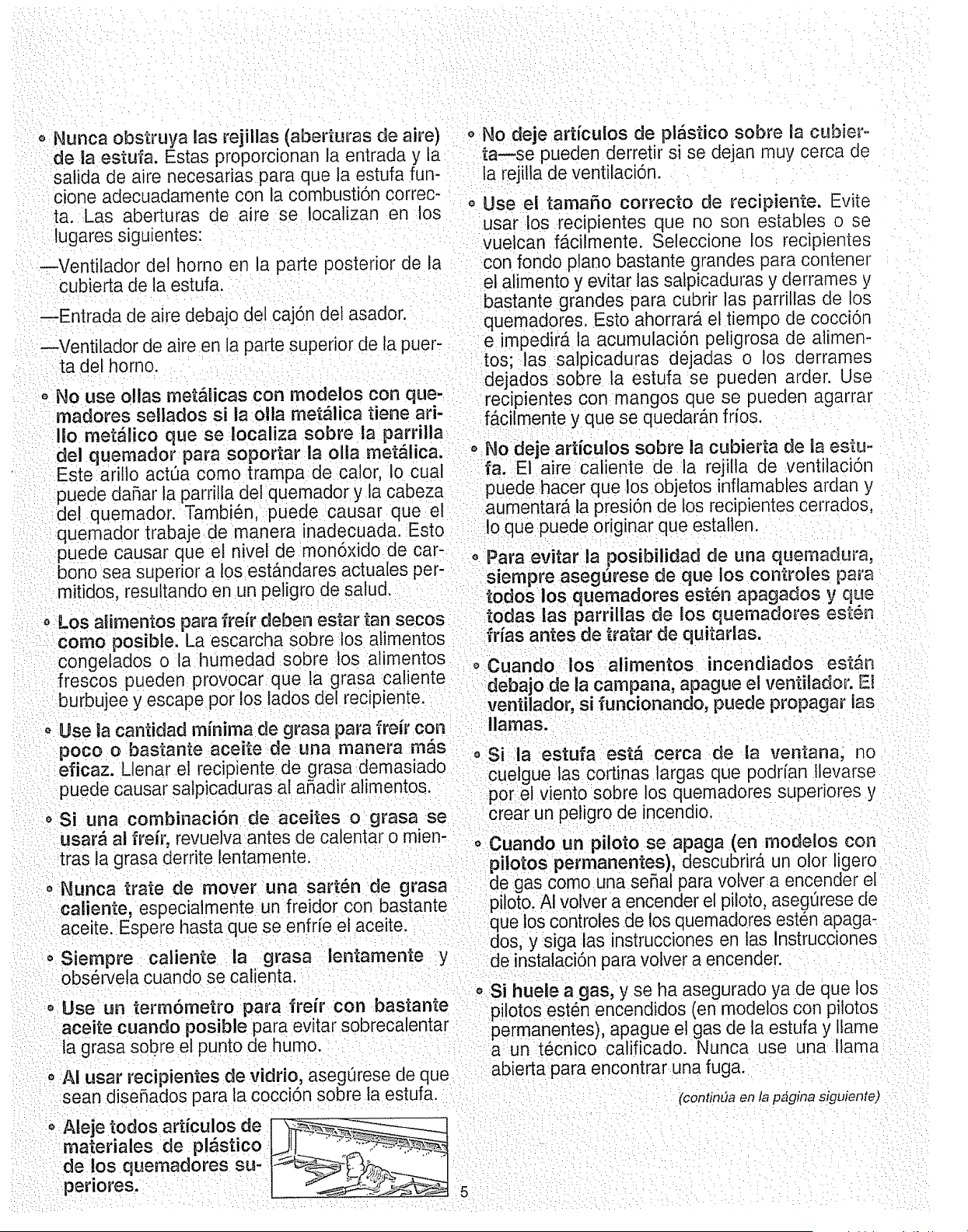
o Nunca obstruya masrejiilas (aberturas de aire)
de ta estufa. Estas proporcionan la entrada y la
salida de aire necesarias para que la estufa fun-
clone adecuadarnente con la combusti6n correc-
ta. Las aberturas de aire se Iocalizan en los
lugares siguientes:
--Ventilador del horno en la parte posterior de la
cubierta de la estufa.
-'Entrada de aire debajo del caj6n det asador.
--Ventifador de aire en ia parte superior de ta puer-
ta del horno.
o No use ollas rnet_iicas con rnodeios con que-
rnadores seHados si la olla met_lica tiene ari-
IIo rnet__lico que se Iocaliza sobre la parriila
del quernador para soportar la olla rnet&lica. °
Este arillo actOa como trampa de calor, 1ocual
puede da_ar la parrilla del quemador y la cabeza
de! quemador. Tambi6n, puede causar que el
quemador trabaje de rnanera inadecuada. Esto
puede causar que el nivel de monoxido de car- o
bono sea superior a los est_.ndares actuales per-
mitidos, resultando en un peligro de safud.
o::Los aiimentos para freir deben estar tan secos
corno posible. La escarcha sobre los atimentos
conge ados o la humedad sobre los alimentos
frescos pueden provocar que ta grasa caliente
burbujee y escape por los lados del recipiente.
°Use la cantidad minima de grasa para freir con
poco o bastante aceite de una rnanera rn_s
eficaz. Llenar el recil:)iente de grasa demasiado
puede causar salpicaduras at a5adir alimentos.
o Si una cornbinaci6n de aceites o qrasa se
usar,_ al freir, revuelva antes de calentar o mien,
tras la grasa derrite lentamente.
oNunca trate de mover una sart_n de grasa
caliente, especialmente un freidor con bastante
aceite. Espere hasta que se enfrie el aceite.
_Siempre caliente la grasa ientarnente y
observela cuando se calienta.
,, No deje articulos de pl_stico sobre la cubier-
ta--se pueden derretir si se dejan muy cerca de
la rejilfa de ventilaci6n.
Use el tarnai_o correcto de recipiente. Evite
usar los recipientes que no son estables o se
vuelcan f_tcilmente. Seleccione los recipientes
con rondo plar_o bastante grandes para contener
el alimento y evitar tas satpicaduras y derrames y
bastante grandes para cubrir las parrillas de los
quemadores Esto ahorrar_t el tiempo de coccion
e impedirb, la acumulaci6n peligrosa de alimen-
tos; las salpicaduras dejadas o los derrames
dejados sobre ta estufa se pueden arder. Use
recipientes con mangos que se pueden agarrar
fb,cilmente yque se quedar_n frios.
No deje articuios sobre la cubierta de ia estu-
fa. El aire caliente de la rejilla de ventilaci6n
puede hacer que los objetos inflamables ardan y
aumentar& la presl6n de los recipientes cerrados,
Io que puede originar que estallen.
Para evitar la posibilidad de una quernadura,
siernpre asegurese de que los controles para
todos los quernadores est_n apagados y que
:todas las parrillas de los quernadores est6n
frias antes de tratar de quitarlas.
Cuando los :alirnentos incendiados est&n
debajo de la carnpana, apague el ventilador. El
ventilador, si funcionando, puede propagar ias
llamas.
,, Si :ia estufa est_ cerca de la ventana, no
cuelgue las cor[inas largas que podrian Ilevarse
porel viento sobre los quemadores superiores y
crear un peligro de incendio.
Cuando :un piloto se apaga (en rnodelos con
pilotos perrnanentes), descubrira un olor ligero
de gas como una se5al para volvera encender el
piloto. AI volver a encender el piloto, asegOresede
que los controles de los quemadores esten apaga-
dos, y siga las instrucciones en las Instrucciones
de instalaci6n para volver a encender.
oUse un terrn6rnetro para freir con bastante
aceite cuando posible para evitar sobrecalentar
la grasa sobre el punto de humo.
abierta para encontrar una fuga.
o AI usar recipientes de vidrio, aseg0rese de que
sean disefiados para la coccion sobre la estufa.
_Si huele a gas, y se ha asegurado ya de que los
pilotos esten encendidos (en modelos con pilotos
permanentes), apague el gas de la estufa y liame
a: un tecnico calificado. Nunca use una llama
(continL'_aen la paghTa siguiente)
o Ateje todos articulos de
materiales de pl&stico
delos quemadores su-
periores. 5
INSTRUCOSONES MPORTANYES DE SEGU
Mmpieza de su estufa
encenderse.
o Qu_dese lejos de la estufa a( abrir la puerta de
un homo caliente._ E! aJre calientey:et Vapor
que escapan: pueden causarquemaduras en
(as manos, ia cara y los ejos.
o iVlantengael horno lirnpio contra lagrasa;
o Coloque las parrillasdet homo en las posi-
ciones deseadas mientras que et horno est_
frfo.
delos con:p
,, Para rnodelos de lira
lirn
SU
o Tirando la parrilla hasta laposici6n en quese ....... tific..r
detiene es una ventaja ai levantar los alimem _ _
tos pesados. Es tambi_n una precauci6ncon_ _ _i __
tra quemaduras_al:: tocar_ las_::_superficies _U_
calientes de la puerta o las paredesdel
La osici6n m_s ba'" " :...... :°._=_ a_. u__._=_._=_
P la R no estadlsenada:: :
para desaizarse.
o No caliente los recipientes cerrados; La pre,
si6n podrfa aumentarl y e[:recipientepodria
estallar, causando daSos,
o No use papel _aluminio en cualquier sitio del
homo excepto como descnto en este manual
Et real manejo podrfa resultar en!un peligr0 de
incendioo daSo a la estufa.:
o A! usar las bolsas de cocci6n o de asar en:el
homo, siga las instrucciones del fabricante.
o Use: s61o_Ios_recipientesde vidrio que se
recorniendan para uso en los hornos de gas,:
o Siernpre quite la: charola asar del:homo
o dei cornpartimiento para asar alfuego direc,
to tan pronto como termine de asar al fuego
directo. La grasa dejada en la char01a se puede
encender si se usa el hornO sin quitar lag rasa de
la charola para asar.
o AI &sat al fuego directo¢: si lacarne est_
demasiado cerca de la llama; la graSa:puede
encenderse: Corte la grasa e×cesiva para:eVitar
que estalle excesivamente.
o Aseg_rese de::que: la charola para asariest_
coJocada correctarnente para reducir;la posibili-
dad de fuegos de grasa.
o Si tuviera fuego de grasaen ta charola _para
asar, apague el: horr{o:y mantenga cerrada::la
puerta para Contener:'el:_:fuego'_ hasta_ quese
apague.
lacubi
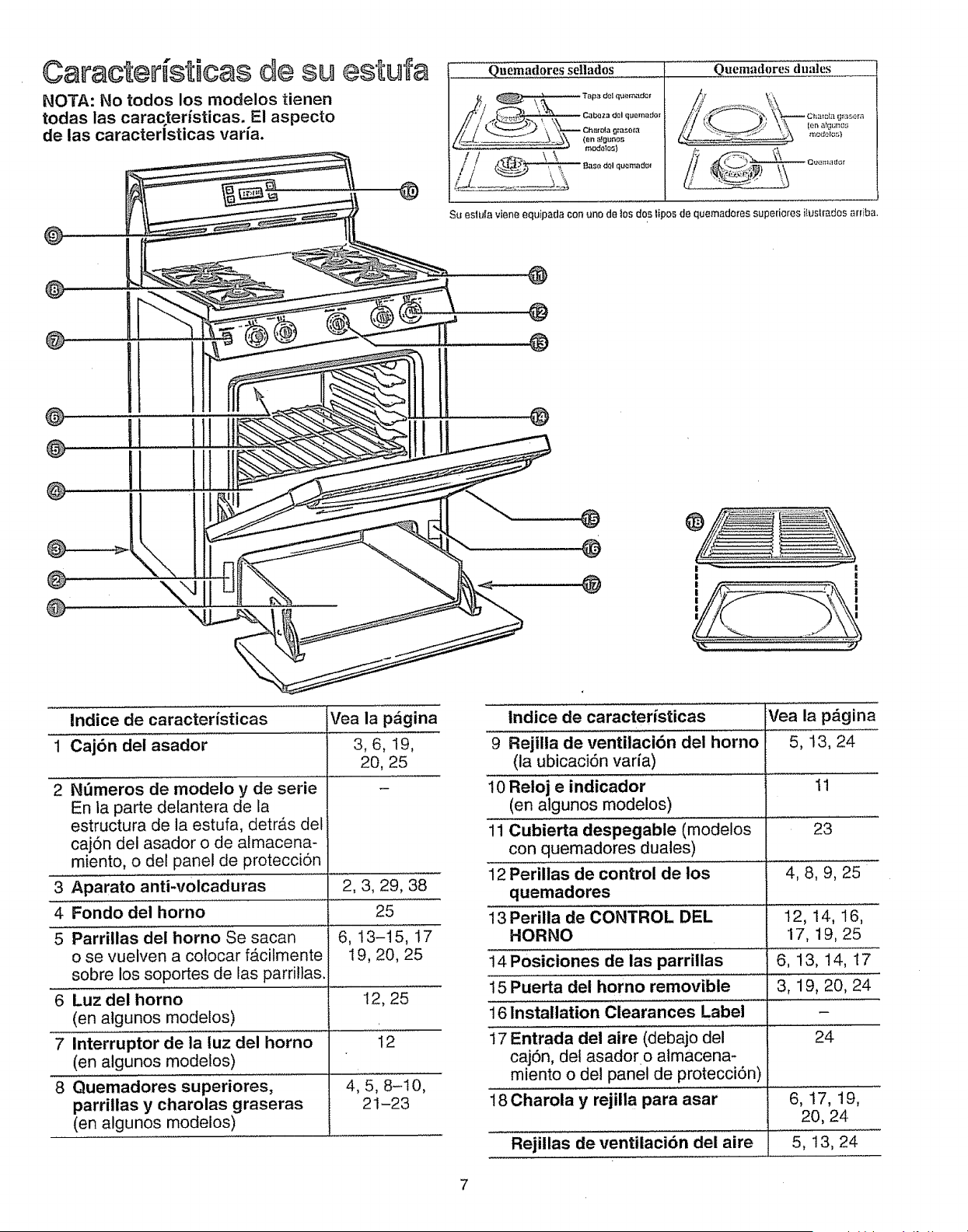
Oaract÷r sticas de su ÷stufa
NOTA" No todos los modelos tienen
todas las caracteristicas. El aspecto
de las caracterlsticas varia.
@
___Quemadores sellados
Quemadores du,'lles
@
@
@
@
@
@
@
@
Indice de caracteristicas Yea la pfigina
1 Caj6n dei asador 3, 6, I9,
20, 25
2 N0meros de modelo y de serie
En la parte delantera de la
estructura de la estufa, detra.s def
caj6n del asador o de almacena-
miento, o del panel de proteccion
3 Aparato anti-volcaduras
2, 3, 29, 38
4 Fondo del homo 25
5 Parrillas dei homo Se sacan 6, t3-15, 17
o se vuelven a colocar fficifmente 19, 20, 25
sobre los soportes de las parrillas.
6 Luz del homo I2, 25
(en algunos modelos)
7 Interruptor de la luz del horno I2
(en algunos modelos)
8 Quemadores superiores, 4, 5, 8-10,
parrillas y charolas graseras 21-23
(en algunos modelos)
lndice de caracteristicas Vea la pfigina
9 Rejilla de ventilacibn dei homo 5, 13, 24
(la ubicaci6n varia)
10 Reloj e indicador 11
(en algunos modelos)
11 Cubierta despegable (modelos 23
con quemadores duales)
12 Perillas de control de los 4, 8, 9, 25
quemadores
13Perilla de CONTROL DEL 12, 14, 16,
HORNO 17, 19, 25
14 Posiciones de las parriUas 6, 13, 14, 17
15 Puerta del homo removible 3, 19, 20, 24
16 Installation Clearances Label
17 Entrada del aire (debajo del 24
caj6n, del asador o almacena-
miento o del panel de protecci6n)
18Charola y rejilla para asar 6, 17, 19,
20, 24
Rejillas de ventilacibn del aire 5, 13, 24
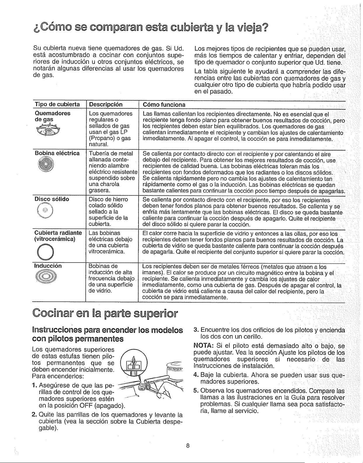
r . = ,_)
&Oorae s÷ cemparan ÷sta cubie a y la vReja°
• y !
Su cubierta nueva tiene quemadores de gas. Si Ud.
est,_ acostumbrado a cocinar con conjuntos supe-
riores de inducci6n u otros conjuntos e!_ctricos, se
notar_n algunas diferencias al usar los quemadores
de gas.
Tipo de cubierta
Quemadores
de gas
Bobina el_ctrica
@
Disco s61ido
(%
Cubierta radiante
(vitrocerfimica)
©
Induccidn
:,,,_iii t/_/.
Descripci6n
Los quemadores
regulares o
sellados de gas
usan el gas LP
(Propano) o gas
natural.
Tuberia de metal
allanada conte-
niendo alambre
el_ctrico resistente
suspendido sobre
una charola
grasera.
Disco de hierro
cofado s61ido
seltado a la
superficie de la
cubierta.
Las bobinas
el_ctdcas debajo
de una cubierta
vitrocer&mica.
Bobinas de
inducci6n de alta
frecuencia debajo
de una superficie
de vidrio.
Los mejores tipos de recipientes que se pueden usari{:_: :i':::i:i:
mas los tiempos de calentar y enfriar, dependen det
tipo de quemador o conjunto superior que Ud: tiene/=:
La tabla siguiente le ayudara a comprender las dife:
rencias entre las cubiertas con quemadores de gas y
cualquier otro tipo de cubierta que habfia podido Usar
en el pasado. :=
C6mo funciona _ .........
Las llamas calientan los recipientes directamente. No es esencial que el ::i;::: ':::::
recipiente tenga fondo piano para obtener buenos resultados de cocci6n, pero : :
los recipientes deben estar bien equilibrados. Los quemadores de gas =: : :::
calientan inmediatamente el recipiente y cambian los ajustes de catentamiento
inmediatamente. AI apagar el control, la cocci6n se para inmediatamente. : ::
Se calienta por contacto directo con e! recipiente y por calentando el aire
debajo del recipiente. Para obtener los mejores resuttados de cocci6n, use : ,:
recipientes de calidad buena. Las bobinas et6ctricas toleran m__slos i
recipientes con fondos deformados que los radiantes o los discos s6 ido& ::
Se calienta rb.pidamente pero no cambia los ajustes de calentamiento tan
rcSpidamente como et gas o la inducci6n. Las bobinas el_ctricas se quedan :
bastante cafientes para continuar la cocci6n poco tiempo despu6s de apagarlas; : i :=
Se calienta por contacto directo con el recipiente, por eso los recipientes ::
deben tener fondos pianos para obtener buenos resultados. Se calienta y se :
enfria m_.s tentarnente que tas bobinas el_ctricas. El disco se queda bastante
caliente para continuar ta coccion despu_s de apagar!o. Quite el recipiente ::
del disco s61ido si quiere parar ta cocci6n. • :
Et calor corre hacia la superficie de vidrio y entonces alas ollas, pot eso los
recipientes deben tener fondos pianos para buenos resuitados de cocci6n. La
cubierta de vidrio se queda bastante caliente para continuar la cocci6n despu_s
de apagarla. Quite el recipiente del conjunto superior si quiere parar la cocci6n.
Los recipientes deben ser de metales ferreos (metales que atraen a los
imanes). El calor se produce por un circuito magn_tico entre la bobina y el
recipiente. Se calienta inmediatamente y cambia los ajustes de cator
inmediatamente, como una cubierta de gas. Despues de apagar el control, la
cubierta de vidrio est_ caliente a causa del calor del recipiente, pero la
cocci6n se para inmediatamente.
Cocinar ÷n lparte superior
lnstruccio ies para encender los modelos
con pilotos permanentes
Los quemadores superiores
de estas estufas tienen pilo-
tos permanentes que se _
deben encender inicialmente,
Para encenderlos:
1. A segQrese de qua tas pe-_&:___
rillas de control de los que-
madores superiores est_n ...........
en la posici6n OFF (apagado).
2. Quite las parriflas de los quemadores y levante ta
cubierta (vea la secci6n sobre la Cubierta despe-
gable).
3. Encuentre los dos orificios de los pilotos y encienda
los dos con un cerillo.
NOTA: Si el piloto est,. demasiado alto o bajo, se
puede ajustar. Vea la secci6n Ajuste los pilotos de los
quemadores superiores si necesario de laS
lnstrucciones de instalaci6n.
4. Baje la cubierta. Ahora se pueden usar sus que-
madores superiores.
5. Observa los quemadores encendidos. Compare las
llamas a las ilustraciones en la Guia para resolver
problemas. Si cualquier llama sea poca satisfacto-
ria, Ilame al servicio.
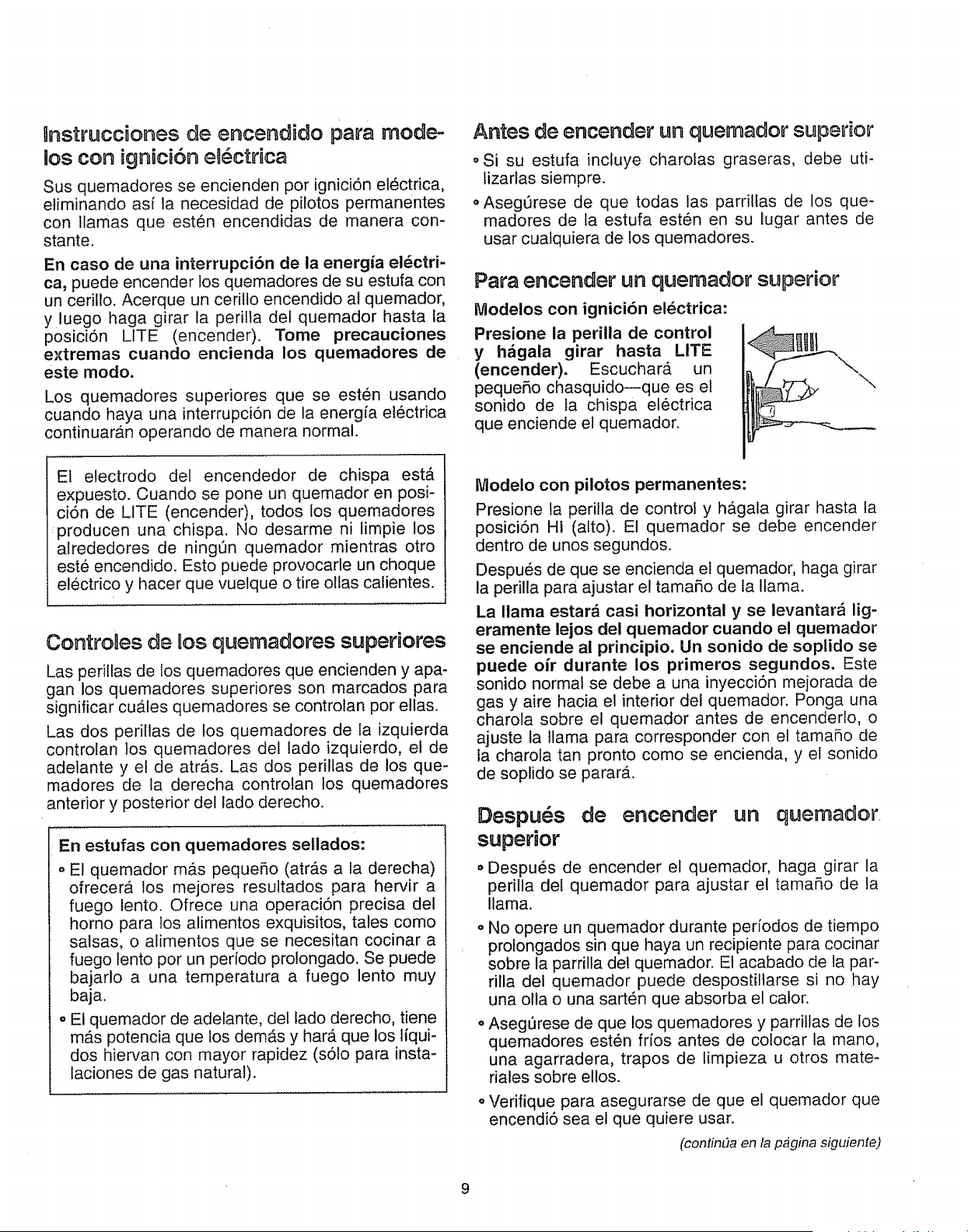
Hnstrucciones de encendido para mode-
los con ignici6n el ctrica
Sus quemadores se encienden por igniciSn et6ctr}ca,
eliminando asf la necesidad de pilotos permanentes
con llamas que esten encendidas de manera con-
stante.
En caso de una interrupci6n de la energia el_ctri-
ca, puede encender los quemadores de su estufa con
un cerillo. Acerque un cerillo encendido al quemador,
y luego haga girar ta peri!la del quemador hasta la
posiciSn LITE (encender). Tome precauciones
extremas cuando encienda los quemadores de
este modo,
Los quemadores superiores que se est_n usando
cuando haya una interrupci6n de la energia el_ctrica
continuar_,n operando de manera normal.
El electrodo del encendedor de chispa est_
expuesto. Cuando se pone un quemador en posi-
ciSn de LITE (encender), todos los quemadores
producen una chispa. No desarme ni limpie los
alrededores de ning_n quemador mientras otro
est_ encendido. Esto puede provocarle un choque
el_ctrico y hacer que vuelque o tire olfas calientes.
Contro es de Bosquemadores superiores
Las perillas de los quemadores que encienden y apa-
gan los quemadores superiores son marcados para
significar cuAles quemadores se controlan por elias.
Las dos perillas de los quemadores de [a izquierda
controlan los quemadores del lado izquierdo, el de
adelante y el de atr_.s. Las dos perillas de los que-
madores de la derecha controlan los quemadores
anterior y posterior del lado derecho.
En estufas con quemadores sellados:
o El quemador m_s peque5o (atrAs a la derecha)
ofrecera los mejores resultados para hervir a
fuego lento. Ofrece una operaciSn precisa del
homo para los alimentos exquisitos, tales como
salsas, o alimentos que se necesitan cocinar a
fuego lento por un perfodo prolongado. Se puede
bajarlo a una temperatura a fuego lento muy
baja.
= El quemador de adefante, del lado derecho, tiene
m&s potencia que los demAs y harA que los liqui-
dos hiervan con mayor rapidez (sSlo para insta-
laciones de gas natural).
Antes de encender un quemador superior
oSi su estufa incluye charolas graseras, debe uti-
lizarlas siempre.
oAsegQrese de que todas las parrilfas de los que-
madores de la estufa esten en su lugar antes de
usar cualquiera de los quemadores.
Para encender un quemador superior
Modelos con ignici6n el_ctrica:
Presione la perilla de control
y h_gala girar hasta LITE
(encender). Escuchar_ un
pequefio chasquido--que es el
sonido de la chispa el_ctrica
que enciende el quemador.
Modelo con pilotos permanentes:
Presione la perilla de control y hagala girar hasta la
posiciSn HI (alto). El quemador se debe encender
dentro de unos segundos.
Despu6s de que se encienda et quemador, haga girar
la perilta para ajustar el tamaSo de la llama.
La llama estar_ casi horizontal y se levantar& lig-
eramente tejos del quemador cuando el quemador
se enciende ai principio. Un sonido de soplido se
puede oir durante los primeros segundos. Este
sonido normal se debe a una inyecciSn mejorada de
gas y aire hacia el interior del quemador. Ponga una
charola sobre el quemador antes de encenderlo, o
ajuste la Itama para corresponder con el tamafio de
la charola tan pronto como se encienda, y el sonido
de soplido se parar_.
Despu s de encender un quemador,
superior
o Despu_s de encender el quemador, haga girar la
perilla de[ quemador para ajustar el tamaSo de la
llama.
o No opere un quemador durante periodos de tiempo
prolongados sin que haya un recipiente para cocinar
sobre la parrilta del quemador. El acabado de la par-
rilla del quemador puede despostiltarse si no hay
una olla o una sart6n que absorba el calor.
oAseg_rese de que los quemadores y parriilas de los
quemadores est_n frios antes de colocar la mano,
una agarradera, trapos de limpieza u otros mate-
dales sobre ellos.
o Verifique para asegurarse de que el quemador que
encendi5 sea el que quiere usar.
(continUa en la pagina siguiente)
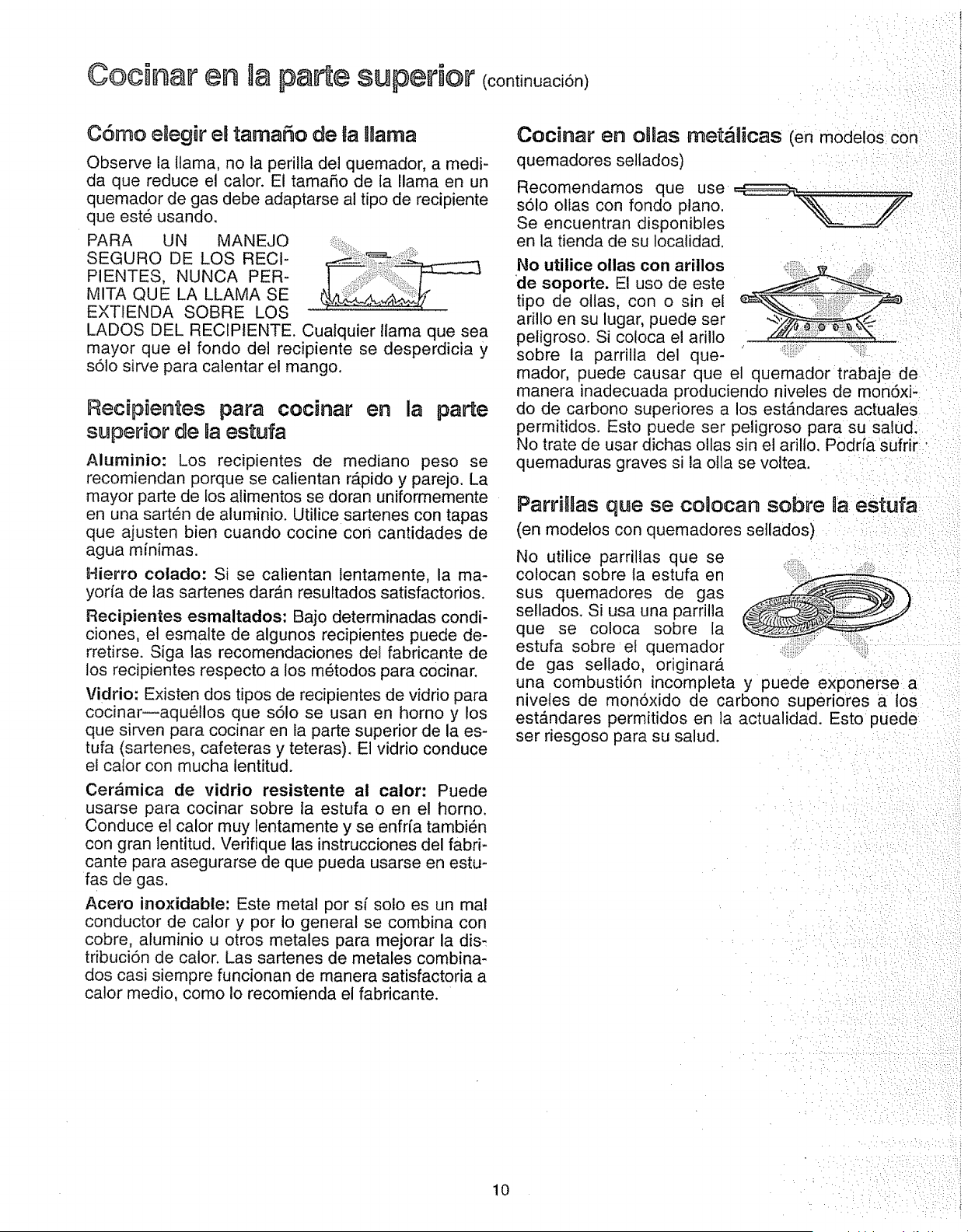
Oooinar en _a par_e supe_'io_ (continuaci6n)
C6mo e_egir el tamafio de ta llama
Observe la llama, no la perilla del quemador, a medi-
da que reduce el calor. El tamafio de Ia llama en un
quemador de gas debe adaptarse al tipo de recipiente
que este usando.
PARA UN MANEJO
SEGURO DE LOS RECl-
PIENTES, NUNCA PER-
MITA QUE LA LLAMA SE
EXTIENDA SOBRE LOS
LADOS DEL REClPtENTE. Cualquier llama que sea
mayor que el rondo del recipiente se desperdicia y
s61o sirve para calentar e! mango.
Recipientes para cocinar en la parte
superior de _aestufa
Aluminio: Los recipientes de mediano peso se
recomiendan porque se calientan rb.pido y parejo. La
mayor parte de los atimentos se doran uniformemente
en una sart_n de aluminio. Utilice sartenes con tapas
que ajusten bien cuando cocine con cantidades de
agua minimas.
Hierro colado: Si se calientan lentamente, la ma-
yoria de tas sartenes dar4n resultados satisfactorios.
Recipientes esmaltados: Bajo determinadas condi-
clones, el esmalte de algunos recipientes puede de-
rretirse. Siga las recomendaciones del fabricante de
los recipientes respecto a los m_todos para cocinar.
Vidrio: Existen dos tipos de recipientes de vidrio para
cocinar--aquellos que s61o se usan en horno y los
que sirven para cocinar en la parte superior de la es-
tufa (sartenes, cafeteras y teteras). El vidrio conduce
el calor con mucha lentitud.
Cer,_mica de vidrio resistente at calor" Puede
usarse para cocinar sobre la estufa o en el horno.
Conduce el calor muy lentamente y se enfrfa tambi_n
con gran lentitud. Verifique las instrucciones del fabri-
cante para asegurarse de que pueda usarse en estu-
fas de gas.
Acero inoxidable: Este metal por si solo es un mal
conductor de calory por Io general se combina con
cobre, aluminio u otros metales para mejorar la dis-
tribuci6n de calor. Las sartenes de metales combina-
dos casi siempre funcionan de manera satisfactoria a
calor medio, como io recomienda el fabricante.
CecJnar en oHas met_licas (en m0delos:icon :_: ::
:: ]
quemadores sellados) ...... ............: :
: : ::: :[: :
Recomendamos que use
s6!o ollas con fondo piano.
Se encuentran disponibles
en la tienda de su Iocalidad.
No utilice oilas con ariilos
'de soporte. El uso de este
tipo de otlas, con o sin el
arillo en su lugar, puede ser
peligroso. Si coloca el arillo __. • .....
sobre la parrilla del que- " '_;:_;ii_::_=:'!iii:
mador, puede causar que el quemador trabaje de :
manera inadecuada produciendo niveles de mon6xi,
do de carbono superiores a los est&ndares actuales
permitidos. Esto puede ser peligroso para su salud.
No trate de usar dichas ollas sin e! arillo. Podria sufr r:
quemaduras graves si la olla se voltea.
ParriHas que se colocan sobre la estufa
(en modelos con quemadores setlados) : ::i
No utilice parrilias que se :,_i_::
colocan sobre ta estufa en ":i_:iz_ili::,
sus quemadores de gas
sellados. Si usa una parrilla
que se coloca sobre la
estufa sobre el quemador .,,
de gas sellado, originar4
una combusti6n incompleta y puede exponerse a
niveles de mon6xido de carbono superiores a los
est,_ndares permitidos en la actualidad. Esto puede
ser riesgoso para su salud.
10
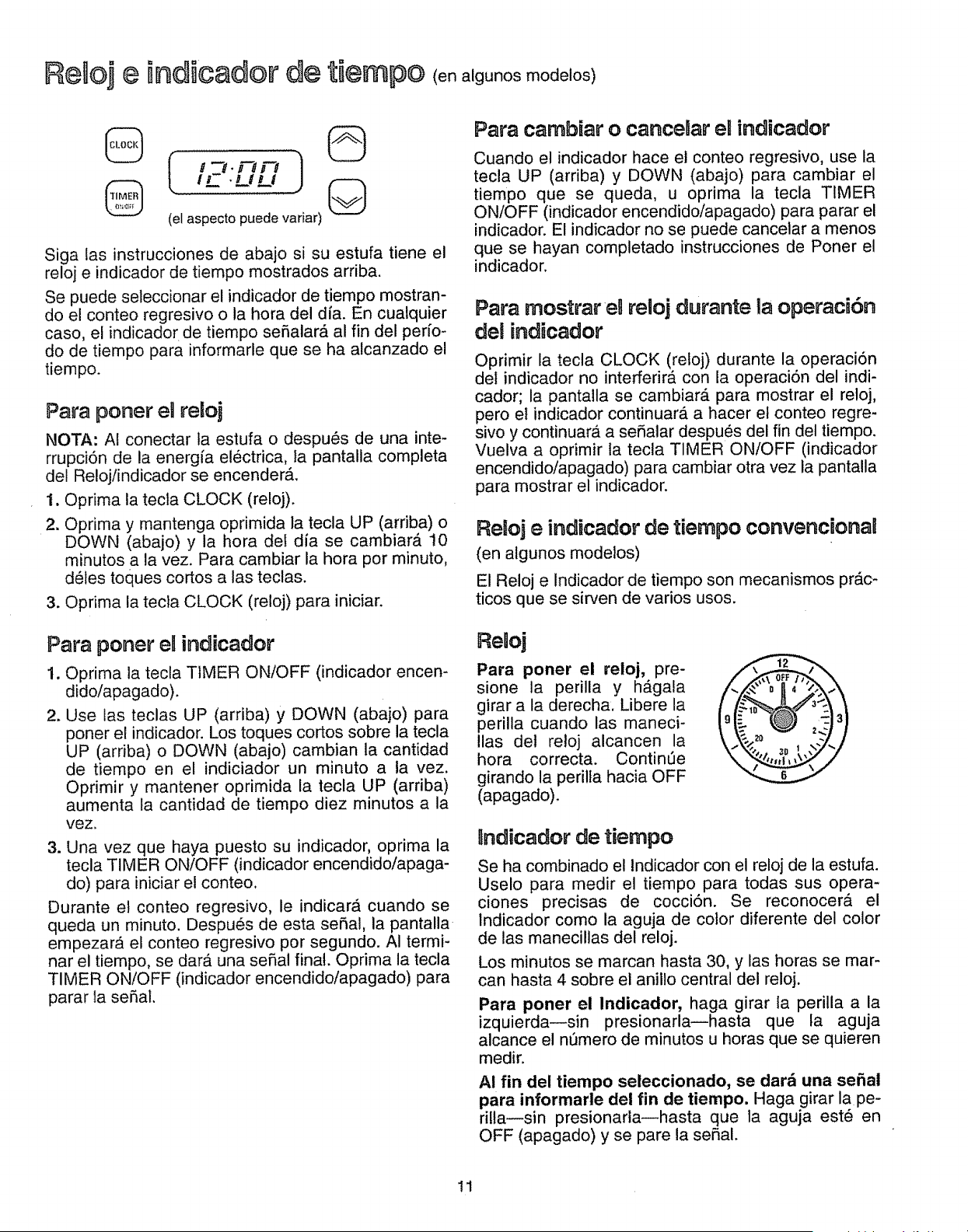
ReUoje indicador de tiempo (enalgunosmodelos)
©
@ [ ©
(el aspecto puede variar)
Siga las instrucciones de abajo si su estufa tiene el
reloi e indicador de tiempo mostrados arriba.
Se puede seleccionar el indicador de tiempo mostran-
do el conteo regresivo o la hora del dfa. En cuatquier
caso, el indicador de tiempo sefialar_, al fin del perfo-
do de tiempo para informarle que se ha alcanzado el
tiempo.
Para porter el reloj
NOTA: A[ conectar la estufa o despu_s de una inte-
rrupci6n de la energfa electrica, la pantalla completa
del Reloj/indicador se encender_.
1. Oprima la tecla CLOCK (reloj).
2. Oprima y mantenga oprimida la tecla UP (arriba) o
DOWN (abajo) y la hora del dia se cambiar_ 10
minutos a la vez. Para cambiar la hora pot minuto,
d61es toques cortos a las teclas.
3. Oprima la tecla CLOCK (reloj) para iniciar.
Para porter e_indicador
1. Oprima la tecla TIMER ON/OFF (indicador encen-
didoiapagado).
2. Use las teclas UP (arriba) y DOWN (abajo) para
poner el indicador. Los toques cortos sobre la tecla
UP (arriba) o DOWN (abajo) cambian la cantidad
de tiempo en el indiciador un minuto a la vez.
Oprimir y mantener oprimida la tecla UP (arriba)
aumenta la cantidad de tiempo diez minutos a la
vez.
3. Una vez que haya puesto su indicador, oprima la
tecla TIMER ON/OFF (indicador encendido/apaga-
do) para iniciar el conteo.
Durante el conteo regresivo, le indicar#, cuando se
queda un minuto. Despues de esta seSal, la pantalla
empezara el conteo regresivo por segundo. AI termi-
nar el tiempo, se dar#, una serial final. Oprima la tecla
TIMER ON/OFF (indicador encendido!apagado) para
parar la seSal.
Para cambiar o cancemarel indicador
Cuando el indicador hace el conteo regresivo, use la
tecla UP (arriba) y DOWN (abajo) para cambiar el
tiempo que se queda, u oprima la tecla TIMER
ON/OFF (indicador encendido!apagado) para parar el
indicador. El indicador no se puede cancelar a menos
que se hayan completado instrucciones de Poner el
indicador.
Para rnostrar el reloj durante la operacibn
del indicador
Oprimir la tecla CLOCK (retoj) durante la operaciSn
det indicador no interferir_, con la operaciSn del indi-
cador; la pantalla se cambiara para mostrar el retoj,
pero et indicador continuarA a hacer et conteo regre-
sivo y continuara a seSalar despu_s del fin del tiempo.
Vuelva a oprimir ta tecla TIMER ON!OFF (indicador
encendido/apagado) para cambiar otra vez la pantalla
para mostrar el indicador.
ReLoj e indicador de tiernpo convencionaE
(en algunos modelos)
El Reloj e Indicador de tiempo son mecanismos pr_c-
ticos que se sirven de varios usos.
Renoj
Para poner el reloj, pre- /,__"_
sione la perilla y hAgala /..
girar a la derecha. Libere la
perilla cuando las maneci-
!las det reloj alcancen la _..20 ..-.:Z/
hora correcta. Contint3e _,,,,_,,_Y
girando la perilfa hacia OFF
(apagado).
nndicador de tiempo
Se ha combinado el Indicador con el reloj de la estufa.
Uselo para medir el tiempo para todas sus opera-
clones precisas de cocciSn. Se reconocera el
lndicador como la aguja de color diferente del color
de las maneciltas del reloj.
Los minutos se marcan hasta 30, y las horas se mar-
can hasta 4 sobre el anillo central dei reloj.
Para porter el Indicador, haga girar la perilla a la
izquierda--sin presionarla--hasta que la aguja
alcance el n_mero de minutos u horas que se quieren
medir.
AI fin del tiempo seleccionado, se dard una sehal
para informarle del fin de tiempo. Haga girar la pe-
riIla--sin presionarla--hasta que ta aguja est_ en
OFF (apagado) y se pare la se5al.
I1

Uso de su homo
Antes de usar su homo
Aseg6rese de entender cSmo poner el panel de con-
trol correctamente. Practique quitar y poner las parri-
Ilas mientras el homo est,, frio. Lea la informacidn y
los consejos de las pAginas siguientes. Tenga este
manual a la mano donde pueda consultarla, en espe-
cial durante las primeras semanas de uso de su
nueva estufa.
lnstrucciones para encender los rnodelos
con pilotos petmanentes
Algunos modelos tienen pilotos permanentes def
homo que se deben encender inicialmente.
Para encender el piloto del homo:
1. Asegt]rese de que la perilla de CONTROL DEL
HORNO est6 en la posici6n OFF (apagado).
2. Abra el caj6n para asar y quite la charola para asar
y la parrilla para asar. Esto facilitarA el acceso al
interior del compartimiento para asar.
3. Encuentre el orificio
del piloto del homo en
la parte trasera del
compartimiento para
asar. Et tubo largo,
corriendo de la parte
delantera a la parte
trasera, es el que-
mador del horno. El
orifico deI piloto est,.
en la parte trasera,
aproximadamente una
pulgada (2.54 cm)
debajo del quemador.
4. Usando un cerillo
largo o un tenedor de
cerillo, tienda la mano
para encender el pilo-
to del homo.
o Para encender el piloto del homo, haga girar la
perilla de CONTROL DEL HORNO hasta la tempe-
ratura deseada. El quemador se debe encender
dentro de 60 segundos.
o Configuracibn correcta de las llamas, durante e!
uso del quemador del homo, verifique Visualmente
la llama del quemador en el compartimiento para
asar. Si la llama no se quema como descrito en la
secci6n de instalaci6n de este libro, ajuste !a llama
siguiendo las instrucciones en esas pAginas.
o lnterrupcibn de la energia el_ctrica: Una interrup-
ci6n de la energfa el_ctrica no afectar_t un piloto per-
manente encendido del homo.
•:
unstrucoio.esparaenoender
con ignic_bn el_ctnca
El quemado, del horno se enciende pOr
eldctrica (en algunos modelos).
Para encender el quemador, haga girar ia
CONTROL DEL HORNO hasta la temperatura desea.;_ :i::,i
da. El quemador debera encenderse dentr0delos=ii:: :
siguientes 30-90 segundos. . : :
Despu_s de que el homo alcance la
seleccionada, el homo realiza un ciclo_se::apaga: :=::i:
completamente y luego se enciende con la llama a :::
toda intensidad--para mantener controlada la tem:-: _ :
peratura del horno. .... :_:
,,_ _ _1 _ :La interrupci6n de energia e ec_ aca ::
PRECAUClON: No intente operar el homo deighi!:
ci6n el_ctrica durante una interrupci6n de: la:
energia electrica. Ni el homo ni el asador pueden:
encenderse sin energia el_ctrica. El gas no fluir_, a
menos que la barra incandescente est6: caliente:::
Si est_ usando el homo cuando falia ia ene:igfa:
el_ctrica, el quemador def homo se apagarA y no:
podr_, volver a encenderse sino hasta que vuelva
la corriente et6ctrica.
[ : :
Control del homo
La perilla de CONTROL DEL
HORNO se encuentra en el
panel de control en la parte
delantera de la estufa.
Sencillamente haga girar la
perilla hasta las temperaturas
de cocci6n deseadas.
La llama se encender_, nor-
malmente despu_s de 30-90
segundos. Despues de que
el homo alcance la tempe-
ratura sefeccionada, el que-
mador del homo cicla--se
apaga completamente, en-
tonces se enciende con una
llama a toda intensidad--
para mantener la temperatu-
ra seleccionada.
..... , •• :•ILi ¸
1:3
o. •:i:: : i¸¸::
:' _ .':: := ,':::':=::'::::i :;::':i_:__i:'J::::ii_:_/:i::!ii
Luz del homo (en algunos modelos): i
: • : : [::: ::
Use el interruptor del panel de control para encender; i: :i:;:i:::
o apagar la luz del horno.
• : _:_ :L _" i "/_'_:_,-:,'::_/_:i
12
• • ! //. : • /: : i •/:•: ::!<:ii:•:_ :
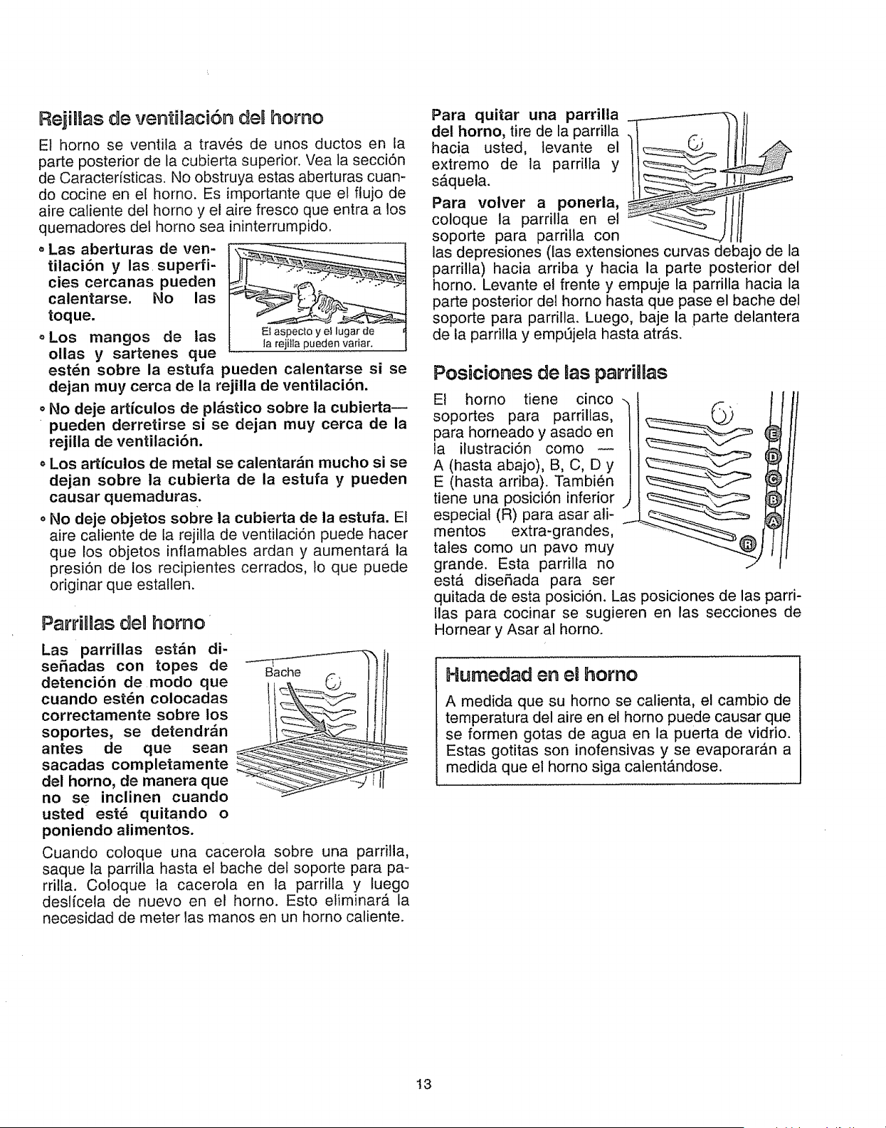
Reiillas de ventiRaci6n deB homo
El homo se ventila a tray,s de unos ductos en la
parte posterior de la cubierta superior. Vea la secci6n
de Caractedsticas. No obstruya estas aberturas cuan-
do cocine en el horno. Es importante que el flujo de
aire caliente del homo y el aire fresco que entra a los
quemadores del horno sea ininterrumpido.
= Las aberturas de ven-
tilacibn y las superfi-
cies cercanas pueden
calentarse. No las
toque.
o Los mangos de las E_aspectoyellugarde
la rejiila pueden variar,
ollas y sartenes que
est6n sobre la estufa pueden calentarse si se
dejan muy cerca de la rejilla de ventilacibn.
oNo deje articulos de ph_stico sobre la cubierta--
pueden derretirse si se dejan muy cerca de la
rejilla de ventilaci6n.
oLos articulos de metal se calentar__n mucho si se
dejan sobre la cubierta de la estufa y pueden
causar quemadura s.
o No deje objetos sobre la cubierta de la estufa. El
aire caliente de la rejilla de ventilaci6n puede hacer
que los objetos inftamables ardan y aumentar_ la
presi6n de los recipientes cerrados, to que puede
originar que estatlen.
ParriHas dea homo
Las parrillas est_n di-
seSadas con topes de Bactte
detenci6n de modo que
cuando est_n colocadas
correctamente sobre los
soportes, se detendrb, n
antes de que sean
sacadas completamente
del homo, de manera que
no se inclinen cuando
usted est_ quitando o
poniendo alimentos.
Cuando coloque una cacerola sobre una parrilla,
saque la parrilfa hasta el bache del soporte para pa-
rrilla. Coloque la cacerola en la parrilta y luego
deslicela de nuevo en el homo° Esto eliminar_ la
necesidad de meter las manos en un homo caliente.
Para quitar una parrilla
del homo, tire de la parrilla
hacia usted, tevante el
extremo de la parrilla y
s&quela.
Para volver a ponerla,
coloque la parrilla en el
las depresiones (ias extensiones curvas debajo de la
parrilla) hacia arriba y hacia la parte posterior del
horno. Levante el frente y empuje la parrilla hacia la
parte posterior del homo hasta que pase el bache del
soporte para parrilla. Luego, baje la parte delantera
de la parrilla y empQjela hasta atr_,s.
Posiciones de las parriUas
El homo tiene cinco -.,
soportes para parrillas,
!
para horneado y asado en
la ilustraci6n como
A (basra abajo), B, C, D y
E (hasta arriba). Tambi6n
tiene una posici6n inferior
especial (R) para asar ali-
mentos extra-grandes,
tales como un pavo muy
grande. Esta parrilla no
est_ diseSada para ser
quitada de esta posici6n. Las posiciones de las parri-
!las para cocinar se sugieren en las secciones de
Hornear y Asar al horno.
Hurnedad en el horno
A medida que su homo se calienta, el cambio de
temperatura del aire en el homo puede causar que
se formen gotas de agua en la puerta de vidrio.
Estas gotitas son inofensivas y se evaporar_.n a
medida que el homo siga calent_.ndose.
I3
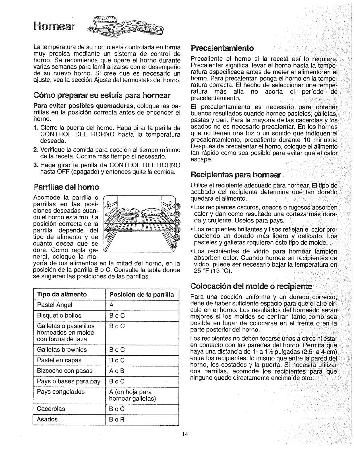
Hornea "
La temperatura de su horno est,. controlada en forma
muy precisa mediante un sistema de control de
horno. Se recomienda que opere el homo durante
varias semanas para familiarizarse con el desempefio
de su nuevo horno. Si cree que es necesario un
ajuste, vea la secci6n Ajuste del termostato del homo.
Cbmo preparar su estufa para hornear
Para evitar posibles quemaduras, coloque las pa-
rrillas en la posici6n correcta antes de encender el
horno.
1. Cierre la puerta det homo. Haga girar la peri!la de
CONTROL DEL HORNO hasta la temperatura
deseada.
2. Verifique la comida para cocci6n al tiempo minimo
de la receta. Cocine m&s tiempo si necesario.
3. Haga girar la perilla de CONTROL DEL HORNO
hasta OFF (apagado) y entonces quite la comida.
Pardi as deJ homo
Acomode la parrilla o
parrillas en las posi-
ciones deseadas cuan-
do e! horno estA frio. La
posici6n correcta de la
parrilla depende del
tipo de alimento y de
cuanto desea que se
dore. Como regla ge-
neral, coloque la ma-
yoria de los alimentos en la mitad del homo, en fa
posici6n de la parrilla B o C. Consulte la tabla donde
se sugieren las posiciones de las parrillas.
Tipo de alimento Posicibn de la parriila
Pastel Angel A
Bisquet o bollos B o C
Galletas o pastelillos B o C
horneados en molde
con forma de taza
Galletas brownies B o C
Pastel en capas B o C
Bizcocho con pasas A o B
Pays o bases para pay B o C
Pays congelados A (en hoja para
hornear galletas)
Cacerolas B o C
Asados B o R
Precaaentamiento
Precaliente el homo si la receta asf Io requiere:
Precalentar significa Ilevar et horno hasta la tempe_
ratura especificada antes de meter el alimentoen el
horno. Para precalentar, ponga el horno en la tempe-
ratura correcta. El hecho de seleccionar una tempe-
ratura ma.s alta no acorta el pefiodo_ de
precalentamiento.
El precalentamiento es necesario para obtener
buenos resultados cuando homee pasteles, galletasi
pastas y pan. Para la mayoria de las cacerolas y los
asados no es necesario precalentar. En los hornos
que no tienen una luz o un sonido que indiquen et
precalentamiento, precaliente durante 10 minut0s:
Despu_s de precalentar el homo, coloque el alimento
tan r_pido como sea posible para evitar que el calor
escape.
Recipientes para hornear
Utilice et recipiente adecuado para hornear. El tipo de
acabado del recipiente determina qu_ tan dorado
quedarA el alimento.
o Los recipientes oscuros, opacos o rugosos absorben
calory dan como resultado una corteza m_.s dora-
day crujiente. Uselos para pays.
o Los redpientes briliantes y lisos reflejan el calor pro,
duciendo un dorado m_s igero y delicado. Los
pasteles y garletas requieren este tipo de molde.
o Los recipientes de vidrio para hornear tambi_n
Colocacibn dea moBde o recipiente =
posible en lugar de colocarse en et frenteo_en_:la,i:: ::_
parte posterior del horno.= =i
Los recipientes no deben tocarse unosa otios:nl/::':===:
en contacto con las paredes del hornol Pefmita
haya una distancia de 1- a l_,4-pulgadas
entre los recipientes, Io mismo que entre la
homo, los costados y la puerta.
dos parrillas, acomode los recipientes' pafai.i:quei=:i:
ninguno quede directamente encima deotro. _i:i::i: :_ii::: _:_=
14
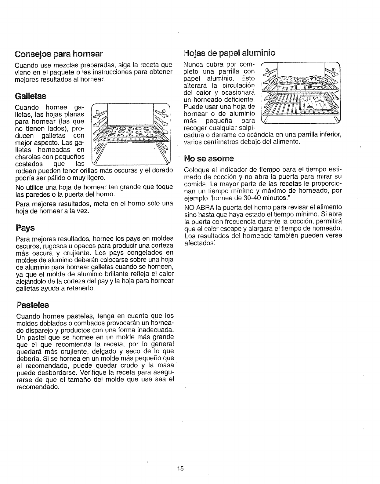
Consejos para hornear
Cuando use mezclas preparadas, siga la receta que
viene en el paquete o tas instrucciones para obtener
mejores resultados al hornear.
GaHetas
Cuando homee ga-
Iletas, las hojas planas
para hornear (las que
no tienen lados), pro-
ducen galletas con
mejor aspecto. Las ga-
Iletas horneadas en
charolas con pequefios
costados que las
rodean pueden tener orillas mas oscuras y el dorado
podria ser p#,lido o muy ligero.
No utilice una hoja de hornear tan grande que toque
las paredes o la puerta del horno.
Para mejores resultados, meta en el homo s61o una
hoja de hornear a la vez.
Pays
Para mejores resultados, hornee los pays en moldes
oscuros, rugosos u opacos para producir una corteza
m&s oscura y crujiente. Los pays congelados en
moldes de aluminio deber_n colocarse sobre una hoja
de aluminio para hornear galletas cuando se horneen,
ya que el molde de aluminio brillante refleja el calor
alej_.ndolo de la corteza del pay y la hoja para homear
galletas ayuda a retenerlo.
Pasteles
Cuando hornee pasteles, tenga en cuenta que los
moldes doblados o combados provocar_n un hornea-
do disparejo y productos con una forma inadecuada.
Un pastel que se hornee en un molde m_s grande
que el que recomienda la receta, por Io general
quedar_ m&s crujiente, delgado y seco de Io que
debeda. Si se homea en un molde m_s pequeSo que
el recomendado, puede quedar crudo y la masa
puede desbordarse. Verifique la receta para asegu-
rarse de que el tamaSo del molde que use sea el
recomendado.
Hojas de papemaluminio
Nunca cubra por com-
pleto una parrilla con
pape} aluminio. Esto
alterar#, la circulaci6n
del calory ocasionar_.
un horneado deficiente.
Puede usar una hoja de
hornear o de aluminio
m&s peque5a para
recoger cualquier salpi-
cadura o derrame colocb.ndola en una parrilla inferior,
varios centfmetros debajo del alimento.
_0 Se asome
Coloque el indicador de tiempo para el tiempo esti-
mado de cocci6n y no abra la puerta para mirar su
comida. La mayor parte de las recetas le proporcio-
nan un tiempo mfnimo y maximo de horneado, por
ejemplo "hornee de 30-40 minutos."
NO ABRA la puerta del homo para revisar el alimento
sino hasta que haya estado el tiempo mfnimo. Si abre
fa puerta con frecuencia durante ta cocci6n, permitir_.
que et calor escape y alargar_, el tiempo de horneado.
Los resultados def horneado tambien pueden verse
afectados:
I
15
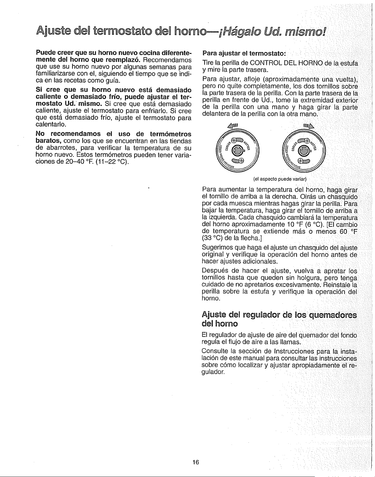
Puede creer que su horno nuevo cocina diferente.
mente del homo que reemplazb. Recomendamos
que use su homo nuevo por algunas semanas para
familiarizarse con el, siguiendo el tiempo que se indi-
ca en las recetas como gufa.
Si cree que su homo nuevo estd demasiado
caliente o demasiado frio, puede ajustar el ter-
mostato Ud. mismo. Si cree que est_ demasiado
caliente, ajuste el termostato para enfriarlo. Si cree
que est,_ demasiado fifo, ajuste el termostato para
calentarlo.
No recomendamos el uso de term6metros
baratos, como los que se encuentran en las tiendas
de abarrotes, para verificar la temperatura de su
homo nuevo. Estos termSmetros pueden tener varia-
clones de 20-40 °F. (!1-22 °C).
y mire ta parte trasera. : _
Para ajustar, afloje (aproximadamente una
pero no quite completamente, los dos torniltos S0bi ....
la parte trasera de la perilla. Con la parte trasera de la :::
perilla en frente de Ud., tome ta extremidad exterior:
de la perilla con una mano y haga girar la
delantera de la perilla con la otra
(elaspecto puedevariar) : i :: :i:i
Para aumentar la temperatura del h0rno, haga girar
el tornillo de arriba a la derecha, oir_.s un chasquido:
por cada muesca mientras hagas girar la perilla. Paral :
bajar la temperatura, haga girar et tornillo de arriba=a
la izquierda. Cada chasquido cambiar_ la temperatura
del homo aproximadamente 10 °F (6 °C). [El cambio
de temperatura se extiende m_s o menos 60 °F
(33 °C) de la flecha,]
Sugerimos que haga el ajuste un chasquido de/ajUste
original y verifique la operaci6n del homo antes de
hacer ajustes adicionales.
Despues de hacer el ajuste, vuelva a apretar los
tornillos hasta que queden sin holgura, pero tenga
cuidado de no apretarlos excesivamente. Reinstale la
perilla sobre ta estufa y verifique la operaci6n del
homo.
Ajuste dell regulador de los quemadores
del homo
El regulador de ajuste de aire del quemador del fondo
regula el flujo de aire alas llamas.
Consulte la seccion de Instrucciones para la insta _
laci6n de este manual para consultar las instrucciones
sobre c6mo Iocalizar y ajustar apropiadamente el re,
gulador.
16
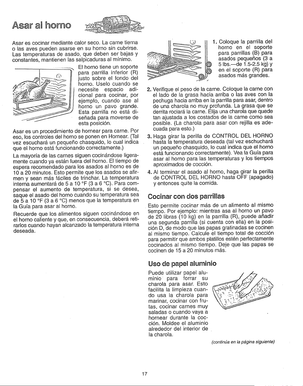
Asar al homo
Asar es cocinar mediante calor seco. La came tierna
o las aves pueden asarse en su homo sin cubrirse.
Las temperaturas de asado, que deben ser bajas y
constantes, mantienen las salpicaduras al mfnimo.
El homo tiene un soporte
para parrilla inferior (R)
justo sobre el rondo del
horno. Usefo cuando se
necesite espacio adi-
cional para cocinar, por
ejemplo, cuando ase al
homo un pavo grande.
Esta parritla no estA di-
sefiada para moverse de
esta posici6n.
Asar es un procedimiento de hornear para carne. Por
eso, los controles dei homo se ponen en Hornear. (Tal
vez escuchara un pequefio chasquido, io cual indica
que el homo est,. funcionando correctamente.)
La mayoria de las cames siguen cocin_tndose ligera-
mente cuando ya estAn fuera del homo. El tiempo de
espera recomendado para los asados al homo es de
10 a 20 minutos. Esto permite que los asados se afir-
men y sean m_.s faciles de trinchar. La temperatura
interna aumentarA de 5 a 10 °F (3 a 6 °C). Para com-
pensar el aumento de temperatura, si se desea,
saque el asado del homo cuando su temperatura sea
de 5 a 10 °F (3 a 6 °C) menos que la temperatura en
la Guia para asar al horno.
Recuerde que los alimentos siguen cocinAndose en
el homo caliente y que, en consecuencia, debera reti-
rarios cuando hayan atcanzado la temperatura interna
deseada.
IL,ooo ue
homo en el soporte
para parriilas (B) para
" , asados pequeffos (3 a
_ _ 5 Ibs.Rde 1.5-2.5 kg) y
_2 enelsoporte(R) Para
asados mAs grandes.
2, Verifique el peso de la came. Coloque la came con
el lado de fa grasa hacia arriba o las aves con la
pechuga hacia arriba en la parrilia para asar, dentro
de una charola no muy profunda. La grasa que se
derrita rociarb_ la carne. Elija una charola que quede
tan ajustada a los costados de la came como sea
posible. (La charola para asar con rejilla es ade-
cuada para esto.)
3, Haga girar la peritla de CONTROL DEL HORNO
hasta la temperatura deseada (tal vez eschuchara
un pequeffo chasquido, io cual indica que el homo
estb. funcionando correctamente). Vea la Gu[a para
asar al homo para las temperaturas y los tiempos
aproximados de cocci6n.
4. AI terminar el asado al homo, haga girar la perilla
de CONTROL DEL HORNO hasta OFF (apagado)
y entonces quite la comida.
Cocinar con dos pardHas
Esto permite cocinar mAs de un alimento al mismo
tiempo. Por ejemplo: mientras asa at homo un pavo
de 20 tibras (10 kg) en la parrilla (R), puede affadir
una segunda parrilta (si cuenta con ella) en la posi-
ci6n D, de modo que las papas gratinadas se cocinen
al mismo tiempo. Calcule el tiempo total de cocci6n
para permitir que ambos platillos est_n perfectamente
cocinados al mismo tiempo. Deje que las papas se
cocinen de 15 a 20 minutos mAs.
Uso de papel aRuminio
Puede utilizar papel alu-
minio para forrar su
charola para asar. Esto
facitita la limpieza cuan-
do usa ia charola para
marinar, cocinar con flu-
tas, cocinar carnes muy
saladas o cuando vaya a
hornear durante la coc-
ci6n. Moldee el aluminio
alrededor del interior de
ta charola.
(continSa en ta pagina siguiente)
17
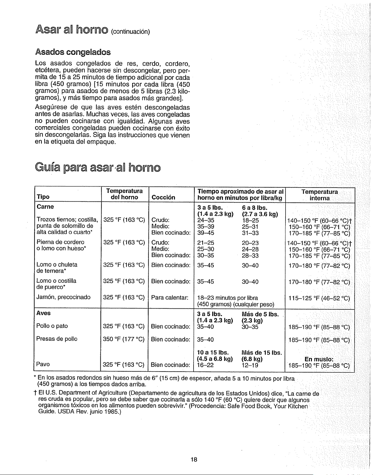
_S_' _ _'_ (continuaci6n)
Asados congeUados
Los asados congelados de res, cerdo, cordero,
etc6tera, pueden hacerse sin descongelar, pero per-
mita de 15 a 25 rninutos de tiempo adicional por cada
libra (450 gramos) [t5 minutos por cada libra (450
gramos) para asados de menos de 5 libras (2.3 kilo-
gramos), y m&s tiempo para asados m_s grandes].
Asegt3rese de que las aves est6n descongeladas
antes de asarlas. Muchas veces, tas aves congeladas
no pueden cocinarse con iguatdad. Algunas aves
comerciates congeladas pueden cocinarse con _xito
sin descongelarlas. Siga las instrucciones que vienen
en la etiqueta de! empaque.
Gu a pata asar aghomo
Temperatura Tiempo aproximado de asar al Temperatura'
Tipo del horno Cocci6n horno en minutos por libra/kg
Came
Trozos tiernos; costilla,
punta de solomillo de
alta calidad o cuarto*
Pierna de cordero
o lomo con hueso*
Lomo o chuleta
'de ternera*
Lomo o costiila
de puerco*
325 °F (163 °C)
325 °F (163 °C)
325 °F (163 °C)
325 °F (163 °C)
Crudo:
Medio:
Bien cocinado:
Crudo:
Medio:
Bien cocinado:
Bien cocinado:
Bien cocinado:
3 a 5 Ibs. 6 a 8 lbs.
(1.4 a 2.3 kg) (2.7 a 3.6 kg)
24-35 18-25
35-39 25-31
39-45 31-33
21-25 20-23
25-30 24-28
30-35 28-33
35-45 30-40
35-45 30-40
140-150 °F (60-66 0C)I _
150-160 °F (66-71 °C)
i70-185 OF(77-85 °C)
140-150 °F (60-66 °C)t
150-160 °F (66-71 °C)
170-185 °F (77-85 °C)
170-180 °F (77-82 °C)
170-180 °F (77-82 °C)
JamSn, precocinado
Aves
Po!lo o pato 325 °F (163 °C) Bien cocinado:
Presas de polio 350 °F (177 °C) Bien cocinado:
Pavo
325 °F (163 °C) Bien cocinado:
325 °F (163 °C)
3 a 5 Ibs.
(1.4 a 2.3 kg)
35-40
35-40
10 a 15 Ibs.
(4,5 a 6.8 kg)
16-22
Para calentar: 18-23 minutos por libra
.......................................(450 gramos) (cualquier,,,peso,),,
M_s de 5 Ibs. ,
(2.3 kg)
30-35
l_l&s de 15 Ibs.
(6.8 kg)
I2-19
115-t25 °F (46-52 °C)
185-190 °F (85_-88 °C)
185-190 OF(85-88 °C)
i85-19o°F(85,88oc):
* En los asados redondos sin hueso m_s de 6" (15 cm) de espesor, aSada 5 a 10 minutos por libra
(450 gramos) a los tiempos dados arriba.
1"E! U.S. Department of Agriculture (Departamento de agricultura de los Estados Unidos) dice, "La came de
res cruda es popular, pero se debe saber que cocinarla a sSlo 140 °F (60 °C) quiere decir que algunos
organismos t6xicos en los alimentos pueden sobrevivir." (Procedencia: Safe Food Book, Your Kitchen
Guide. USDA Rev. junio 1985.)
18
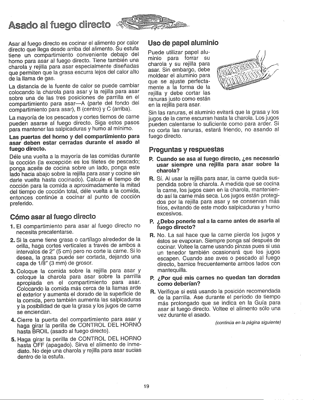
Asado fuego directo
Asar al fuego directo es cocinar et alimento por calor
directo que Ilega desde arriba del atimento. Su estufa
tiene un compartimiento conveniente debajo del
homo para asar al fuego directo. Tiene tambi_n una
charola y rejilla para asar especialmente dise_adas
que permiten que la grasa escurra lejos del calor alto
de la llama de gas.
La distancia de la fuente de calor se puede cambiar
colocando la charola para asar y ta rejilta para asar
sobre una de las tres posiciones de parrifla en el
compartimiento para asar--A (paRe del fondo del
compartimiento para asar), B (centro) y C (arriba).
La mayoria de los pescados y cortes tiemos de came
pueden asarse al fuego directo. Siga estos pasos
para mantener las salpicaduras y humo al minimo.
Las puertas del horno y del compartimiento para
asar deben estar cerradas durante el asado al
fuego directo,
D61e una vuelta a la mayorfa de las comidas durante
la cocci6n (la excepci6n es los filetes de pescado;
ponga aceite de cocina sobre un lado, ponga este
lado hacia abajo sobre la rejilla para asar y cocine sin
darle vuelta hasta cocinado). Calcule el tiempo de
cocci6n para la comida a aproximadamente la mitad
del tiempo de cocci6n total, d61e vuelta a la comida,
entonces continQe a cocinar al punto de cocci6n
preferido.
Cbmo asar al fuego directo
1. El compartimiento para asar al fuego directo no
necesita precalentarse.
2. Si la came tiene grasa o carfilago alrededor de la
orilla, haga cortes verticales a trav_s de ambos a
intervalos de 2" (5 cm) pero no corte la came. Si Io
desea, la grasa puede set cortada, dejando una
capa de t/8" (3 mm) de grosor.
3, Coloque la comida sobre la rejilla para asar y
coloque la charola para asar sobre la parrilla
apropiada en el compartimiento para asar.
Colocando la comida m&s cerca de la llamas arde
el exterior y aumenta el dorado de la superficie de
la comida, pero tambi_n aumenta las salpicaduras
y la posibilidad de que la grasa y los jugos de came
se enciendan.
4. Cierre la puerta del compartimiento para asar y
haga girar la perilla de CONTROL DEL HORNO
hasta BROIL (asado al fuego directo).
5. Haga girar la perifla de CONTROL DEL HORNO
hasta OFF (apagado). Siwa el alimento de inme-
diato. No deje una charota y rejilla para asar sucias
dentro de ia estufa.
Uso de papel a urninio
Puede utilizar papel alu-
minio para forrar su
charola y su rejitla para
asar. Sin embargo, debe
moldear el aluminio para
que se ajuste perfecta-
mente a la forma de ia
rejilla y debe cortar las
ranuras justo como est_,n
en fa rejilfa para asar,
y ....
Sin las ranuras, el aluminio evitara que la grasa y los
jugos de la came escurran hasta la charotao Los jugos
pueden calentarse io suficiente como para arder. Si
no corta las ranuras, estar& friendo, no asando al
fuego directo.
Preguntas y respuestas
R Cuando se asa al fuego directo, &es necesario
usar siempre una rejilla para asar sobre la
charola?
R. Si. A! usar la rejilla para asar, la came queda sus-
pendida sobre la charola. A medida que se cocina
la came, los jugos caen en la charola, mantenien-
do asi la came mAs seca. Los jugos est&n protegi-
dos por la rejilla para asar y se conservan mas
frios, evitando de este modo salpicaduras y humo
excesivos.
P, &Debo ponerle sal a la came antes de asarla al
fuego directo?
R. No. La sal hace que la came pierda los jugos y
estos se evaporan. Siempre ponga sal despues de
cocinar. Voltee la came usando pinzas pues si usa
un tenedor tambien ocasionar& que los jugos
escapen. Cuando ase aves o pescado al fuego
directo, barnice frecuentemente ambos lados con
mantequilla.
P. &Pot qu6 mis carnes no quedan tan doradas
como deberian?
R, Vefifique si ester usando la posici6n recomendada
de ta parrilla. Ase durante el periodo de tiempo
mas prolongado que se indica en la Guia para
asar al fuego directo. Voltee el atimento s61o una
vez durante el asado.
(continda en fa pagina siguiente)
19
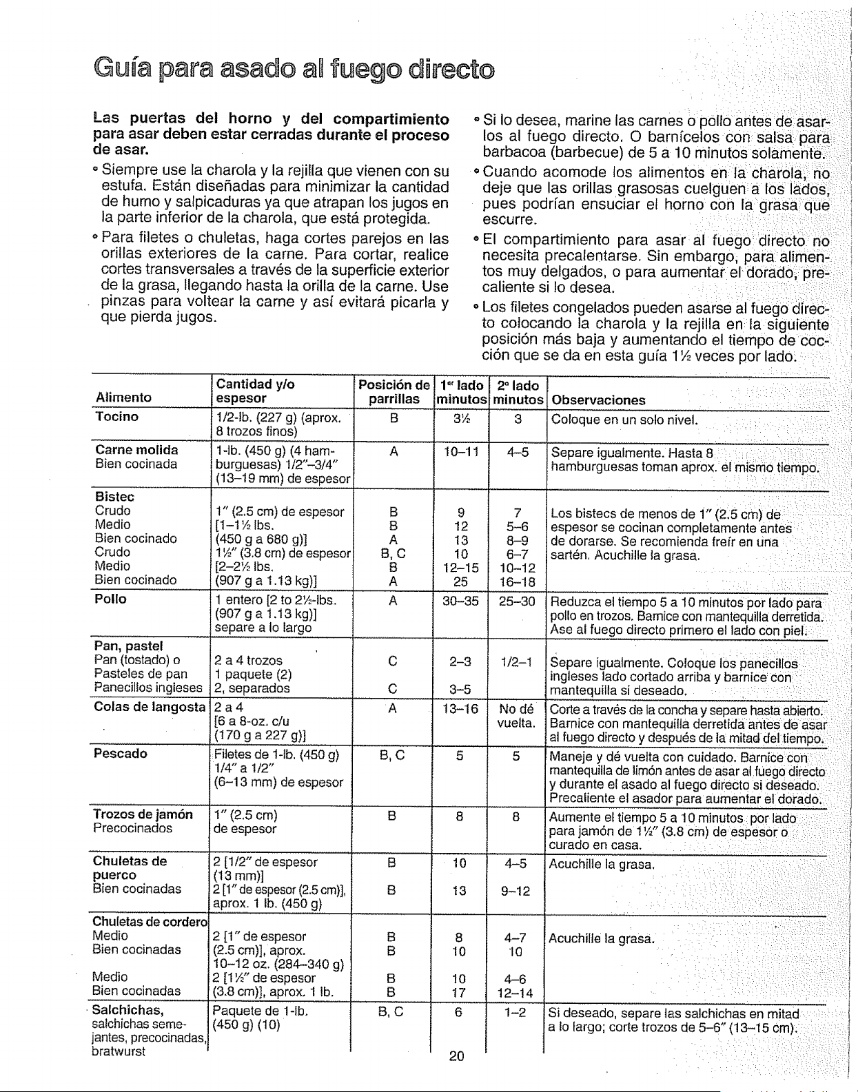
Gu a para asado fuego di ecto
Las puertas del horno y del compartimiento
para asar deben estar cerradas durante el proceso
de asar.
o Siempre use la charola y la rejilla que vienen con su
estufa. EstAn diseSadas para minimizar la cantidad
de humo y salpicaduras ya que atrapan los jugos en
la parte inferior de la charola, que estA protegida.
o Para filetes o chuletas, haga cortes parejos en las
orillas exteriores de la carne. Para cortar, realice
cortes transversales a trav_s de la superficie exterior
de la grasa, llegando hasta fa orilla de la carne. Use
pinzas para voltear la came y asi evitar& picarla y
que pierda jugos.
Atimento
Tocino
o Si Io desea, marine las cames o
los al fuego directo. O
barbacoa (barbecue) de 5 a 10 minutos sola
• Cuando acomode los alimentos en:ta=Chi
deje que las orillas grasosas cuelguen a
pues podrfan ensuciar el homo con la
escurre.
o El compartimiento para asar: al fueg
necesita precalentarse. Sin embargo, para alimen- ii:i::i
tos muy delgados, 0 para aumentar el, dorad0i: pre-:i:::::i:=
caliente si 10 desea. : :
o Los filetes congelados pueden asarse
to cotocando la charola y la rejilla en::la siguiente::::: i
posici6n m_s baja y aumentando el tiempo de COc_:<:'::
ci6n que se da en esta guia 1½ veces por lado:,
Cantidady/o Posici6nde l"'lado 2"lado ..... :.... .x.......,
jespesor parrillas Eminutos minutos Observaciones
1/2-1b. (227 g) (aprox. B 3½ 3 Coloque en un solo nivel. .....
8trozosfinos) : i : i _::
Came molida l-lb. (450 g) (4 ham-
Bien cocinada burguesas) 1/2"--3/4"
: (13-!9 mm) de espesor
Bistec
Crudo 1" (2.5 cm) de espesor
Medio [I-1½ lbs.
Bien cocinado (450 g a 680 g)]
Crudo 1½" (3.8 cm) de espesor
Medio [2-2V= ibs.
Bien cocinado : (907 g a 1:13 kg)] ,
Po!lo 1 entero [2 to 2Y_-lbs.
(907 g a 1.t3 kg)]
separe a Io largo
Pan, pastel
Pan (tostado) o 2 a 4 trozos
Pasteles de pan t paquete (2)
Paneciliosingleses 2, separados
Colas de langosta 2 a 4
[6 a 8-oz. c/u
(170 g a 227 g)]........
Pescado Fitetes de l-lb. (450 g)
1/4" a 1/2"
(6-13 mm) de espesor
Trozos de jarn6n ................1";;"(2.5cm)
Precocinados de espesor
Chuletas de 2 [1/2" de espesor
puerco (13 mm)]
Bien cocinadas !2 [1" de espesor(2.5cm)],
iaprox. 1 lb. (450 g)
Chuletas de cordero
Medio 2 [1" de espesor
Bien cocinadas (2.5 cm)], aprox.
10-12 oz. (284-340 g)
2 [1½" de espesor
(3.8 cm)], aprox. 1 lb.
Paquete de l-lb.
(450 g) (10)
Medio
Bien cocinadas
•Salchichas,
salchichas seme-
jantes, precocinada._
bratwurst
A
B
B
A
B,C
B
A
A
C
c
10-11 4-5
9 7
12 5-6
13 8-9
10 6-7
12-15 10-12
25 16-18
30-35 25-30
2-3 I/2-1
3-5
A 13-16 No d_
B,C
B
B
B
B
B
B
B
B,C
vuelta.
5 5
8 8
10 4-5
13 9-12
8 4-7
10 10
10 4-6
17 12-14
1-2
Separe iguaimente. Hasta 8: : _:::::::;::::::: ::::::i
hamburguesas toman aprox.:el
Los bistecs de menos de 1" (215:::::::::::::::::::::
espesor se eocinan completamente antes : :::
de dorarse. Se recomienda frei'r en una ::=::: :
sart_n. Acuchille la grasa. : :::::
.......... ...... :[ :
Reduzca el tiempo 5 a 10 minutos por lado para:::
polio en trozos. Barnice con mantequilta derretidai=:: i
Ase al fuego directo prirnero el lado con Pieli : ::i::i
Separe iguatmente. Coloque
ingleses lado cortado arriba y bamice con
mantequilla si deseado .... i::::
Corte a tray,s de la concha y separe hasta abierto_ ": ::=
Bamice con mantequilla derretida antes de asar::::::
ial fuego directo y despu_s de la mitad del tiemp0,::i::::::
_Maneje y de vuelta con culdado. Barnfce con::.:::: :::::
mantequilla de lim6n antes de asar al fueg0 direct0 :::::::::
y durante el asado al fuego directo si deseado
Precaliente el asador para aumentar el dotadol ::
...... ,, ,,,,,;,, ,, : :
Aumente el tiempo 5 a 10 minutos ::por lad0 :: :::::i
para jamon de 1 ½ (3.8 cm) deespes0[ 0:::
curado en casa. : ....:i::i::::::
.... ,,,,,,,,;,,,, ,
Acuchitte la grasa,
AcuchilIe,agrasa. =
i= :
Si deseado, separe tas salchichas en
ale largo; corte trozes de 5-6" (13-15 era);
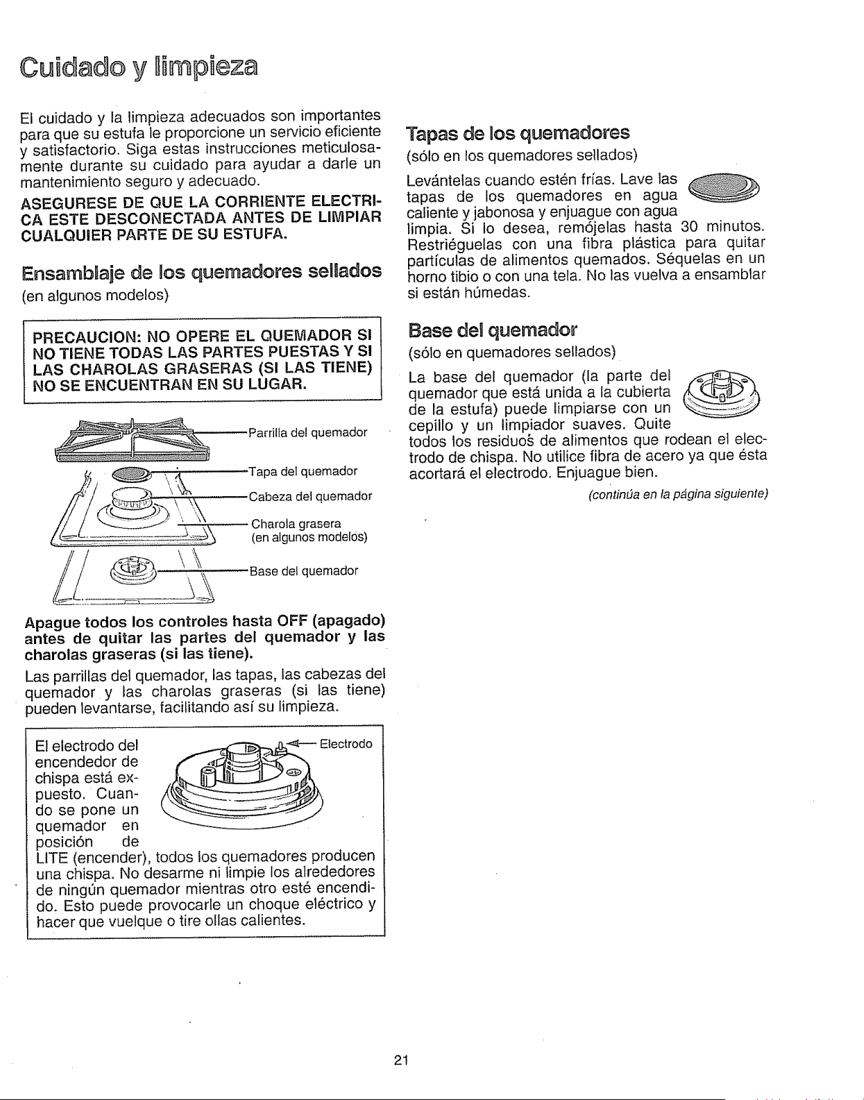
Cuidado y Hmpieza
El cuidado y la limpieza adecuados son importantes
para que su estufa le proporcione un servicio eficiente
y satisfactorio. Siga estas instrucciones meticulosa-
mente durante su cuidado para ayudar a darle un
mantenimiento seguro y adecuado.
ASEGURESE DE QUE LA CORRIENTE ELECTRI-
CA ESTE DESCONECTADA ANTES DE LIMPIAR
CUALQUIER PARTE DE SU ESTUFA.
EnsambRaje de Jos quemadores seHados
(en algunos modetos)
PRECAUClON: NO OPERE EL QUEMADOR Si
NO TIENE TODAS LAS PARTES PUESTAS Y Sl
LAS CHAROLAS GRASERAS (Si LAS TIENE)
NO SE ENCUENTRAN EN SU LUGAR,
.... Parrilla del quemador
_4/_/ ,, _ ......Tapa de, quemador
..... ,_ ,_j.......... Cabeza del quemador
..__\ Charola grasera
(en algunos modelos)
Apague todos los controles hasta OFF (apagado)
antes de quitar las partes del quemador y las
charolas graseras (si las tiene).
Las parrillas det quemador, las tapas, las cabezas del
quemador y tas charolas graseras (si las tiene)
pueden levantarse, facilitando as[ su limpieza.
El electrodo del
encendedor de
chispa estA ex-
puesto. Cuan-
do se pone un
quemador en
posici6n de
LITE (encender), todos los quemadores producen
una chispa. No desarme ni timpie los alrededores
de ningQn quemador mientras otto est6 encendi-
do. Esto puede provocarte un choque el_ctrico y
hacer que vuelque o tire ollas calientes.
Tapas de Rosquemadores
(s61o en los quemadores sellados)
Lev_ntelas cuando esten frias. Lave las
tapas de los quemadores en agua
caliente y jabonosa y enjuague con agua
limpia. Si 1o desea, rem6jelas hasta 30 minutos.
Restri_guelas con una fibra ptastica para quitar
part[culas de atimentos quernados. S_quelas en un
homo tibio o con una tel& No las vuelva a ensamblar
si est_.n hQmedas.
Base quemador
(s6Io en quemadores sellados)
La base del quemador (la parte del
quernador que estA unida a la cubierta
de la estufa) puede limpiarse con un
cepillo y un limpiador suaves. Quite
todos los residuo_ de alimentos que rodean et elec-
trodo de chispa. No utilice fibra de acero ya que esta
acortar_, el electrodo. Enjuague bien.
(continUa en ta p_gina siguiente)
21
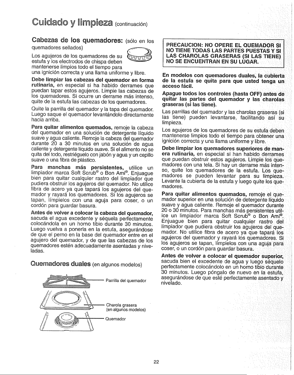
Cuidado y nimpieza Icont nu c o)
Cabezas de quemadores: (s61oen los
quemadores sellados)
Los agujeros de los quemadores de su
estufa y los electrodos de chispa deben
mantenerse limpios todo el tiempo para
una igniciSn correcta y una llama uniforme y libre.
Debe limpiar las cabezas del quemador en forma
rutinaria, en especial si ha habido derrames que
puedan tapar estos agujeros. Limpie las cabezas de
los quemadores. Si ocurre un derrame m&s intenso,
quite de fa estufa las cabezas de los quemadores.
Quite la parritla del quemador y la tapa del quemador.
Luego saque et quemador levantgndolo directamente
hacia arriba.
Para quitar alimentos quemados, remoje la cabeza
del quemador en una soluci6n de detergente lfquido
suave y agua caliente. Rernoje la cabeza del quemador
durante 20 a 30 minutos en una soluci6n de agua
caliente y detergente liquido suave. Si el alimento no se
quita del todo, restrieguelo con jab6n y agua y un cepillo
suave o una fibra de pl_.stico.
Para manchas m__s persistentes, utilice un
limpiador marca Soft Scrub ® o Bon AmP. Enjuague
bien para quitar cualquier rastro del limpiador que
pudiera obstruir los agujeros del quemador. No utilice
fibra de acero ya que tapar& los agujeros del que-
mador y rayara los quemadores. Si los agujeros se
tapan, fimpietos con una aguja para coser, o un
cord6n para guardar basura.
Antes de volver a colocar la cabeza del quemador,
sacuda el agua excedente y s_quela perfectamente
coloc#,ndola en un homo tibio durante 30 minutos.
Luego vuelva a ponerla en ia estufa, asegur_ndose
de que el perno en la base del quemador entre en el
agujero del quemador, y de que las cabezas de los
quemadores est_n adecuadamente asentadas y nive-
ladas.
Quemadores duaMes (en algunos modelos)
Parrilla del quemador
Charola grasera
(en algunos modelos)
Quemador
i _, .... • _ •
, :, i_i_ii!_i(!i/I :_;iilill
• • i_ • ":/i;:: ::i:
• • ,, "i "(:i _ii'i: _
PRECAUCION: NO OPERE EL QUEiVIADOR..... Si
NO TIENE TODAS LAS PARTES PUESTASY Si
LAS CHAROLAS GRASERAS (SI LAS TIENE)
NO SE ENCUENTRAN EN SU LUGAR, I
En rnodelos con quemadores duales_ la cubiei_a: :i:
de la estufa se quita para que usted tenga:un::: i
acceso f_cil. : : i_
Apague todos los controles (basra OFF) antes de_::;:i
quitar las partes del quemador y las charolas _:
graseras (si las tiene).
Las parritlas del quemador y las charolas graseras (sil
las tiene) pueden levantarse, facilitando asf su i
limpieza.
Los agujeros de los quemadores de su estufa deben :'
mantenerse limpios todo el tiempo para obtener Una :i :
ignici6n correcta y una llama uniforme y libre. _
Debe limpiar los quemadores superiores de man"
era rutinaria, en especial si han habido derrames :,_::
que puedan obstruir estos agujeros, Eimpie los que,:
madores con una tela. Si hay un derrame m,_s inteml
so, quite los quemadores de la estufa. Los que:.i ::
madores se pueden levantar para su limpiezai =
Levante ia cubierta de la estufa y luego quite los que,
madores.
Para quitar alimentos quemados, remoje el que_:: i:
mador superior en una soluci6n de detergente Ifquido
suave y agua caliente. Remoje el quemador durante
20 o 30 minutos. Para manchas rags .peersistentes utiet-:
ice un limpiador marca Soft Scrub o Bon Ami,
Enjuague bien para quitar cualquier rastroldel:
timpiador que pudiera obstruir los agujeros del que_
mador. No utilice libra de acero ya que taparA ' los
agujeros del quemador y rayarA los quemadoreS.: Si: :
los agujeros se tapan, limpielos con una agujap:ara :i i
coser, o un cord6n para guardar basura:
Antes de volver a colocar el
sacuda bien el excedente de agua y luego s_quelo :::::
perfectamente colocAndolo en un homo tibi6 durante:: ::ii
30 minutos. Luego p6ngalo de nuevo en la
asegurandose de que este perfectamente asentadO i
nivelado, iii i :
22
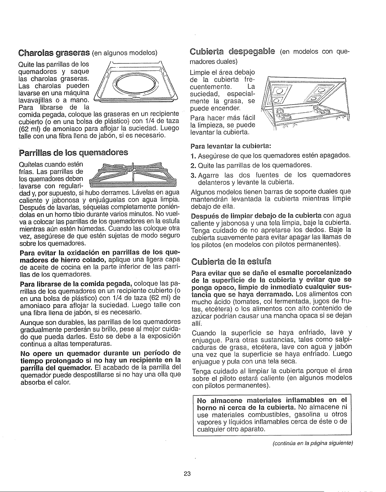
CharoRas graseras
(en atgunos modelos)
'%,,+ 2'
Quite las parrillas de los
quemadores y saque
las charolas graseras.
Las charolas pueden
lavarse en una m_quina
lavavajillas o a mano.
Para librarse de la
comida pegada, co!oque tas graseras en un recipiente
cubierto (o en una bolsa de pl_.stico) con 1/4 de taza
(62 ml) de amoniaco para aflojar la suciedad. Luego
talle con una fibra ltena de jab6n, si es necesario.
ParriHas de los quemadores
Quitelas cuando est6n
frias. Las parri!las de
los quemadores deben
lavarse con regulari-
dad y, por supuesto, si hubo derrames. Lgtvelas en agua
caliente y jabonosa y enjuAguelas con agua fimpia.
Despu_s de lavarlas, s_quelas completamente poni_n-
dolas en un homo tibio durante varios minutos. No vuel-
va a colocar las parrillas de los quemadores en la estufa
mientras ann est6n hQmedas. Cuando las coloque otra
vez, asegQrese de que est6n sujetas de modo seguro
sobre los quemadores+
Para evitar la oxidaci6n en parrillas de los que-
madores de hierro colado, aplique una ligera capa
de aceite de cocina en la parte inferior de las pard-
tlas de los quemadores.
Para librarse de la comida pegada, coloque las pa-
rrillas de los quemadores en un recipiente cubierto (o
en una bolsa de pl_.stico) con 1/4 de taza (62 ml) de
amoniaco para aflojar la suciedad+ Luego talle con
una fibra Ilena de jab6n, si es necesario.
Aunque son durables, las parrillas de los quemadores
gradualmente perdera.n su brilto, pese a! mejor cuida-
do que pueda darles. Esto se debe a la exposici6n
continua a altas temperaturas.
No opere un quemador durante un periodo de
tiempo proiongado si no hay un recipiente en la
parrilla del quemador. El acabado de la parri!la del
quemador puede despostillarse si no hay una olta que
absorba el calor.
CubSerta despegabHe
madores duafes)
Limpie el Area debajo
de ta cubierta fie-
cuentemente. La
suciedad, especial-
mente la grasa, se
puede encender.
Para hacer mgts fdtcit
la limpieza, se puede
levantar la cubierta.
(en modelos con que-
Para levantar la cubierta:
1. AsegOrese de que los quemadores est_n apagados.
2. Quite las parrillas de los quemadores+
3. Agarre las dos fuentes de los quemadores
detanteros y levante la cubierta.
Algunos rnodelos tienen barras de soporte duales que
mantendr_.n levantada fa cubierta mientras limpie
debajo de ella.
Despu6s de limpiar debajo de la cubierta con agua
caliente y jabonosa y una teta limpia, baje la cubierta.
Tenga cuidado de no apretarse los dedos. Baje la
cubierta suavemente para evitar apagar las llamas de
los pilotos (en modelos con pilotos permanentes),
CubHerta de Haestufa
Para evitar que se daSe ei esmalte porcelanizado
de la superficie de la cubierta y evitar que se
ponga opaco, limpie de inmediato cualquier sus-
tancia que se haya derramado. Los alimentos con
mucho _cido (tomates, col fermentada, jugos de flu-
tas, etcetera) o los alimentos con alto contenido de
azOcar podrian causar una mancha opaca si se dejan
alli_
Cuando la superficie se haya enfriado, lave y
enjuague+ Para otras sustancias, tales como salpi-
caduras de grasa, etc_tera, lave con agua y jab6n
una vez que la superficie se haya enfriado. Luego
enjuague y pula con una tela seca.
Tenga cuidado al timpiar la cubierta porque el Area
sobre e! piloto estar_, caliente (en algunos modelos
con pifotos permanentes).
No almacene materiales inflamables en el
homo ni cerca de la cubierta. No almacene ni
use materiales combustibles, gasolina u otros
vapores y liquidos inflamables cerca de _ste o de
cualquier otto aparato.
(continda en ta pbgina siguiente)
23
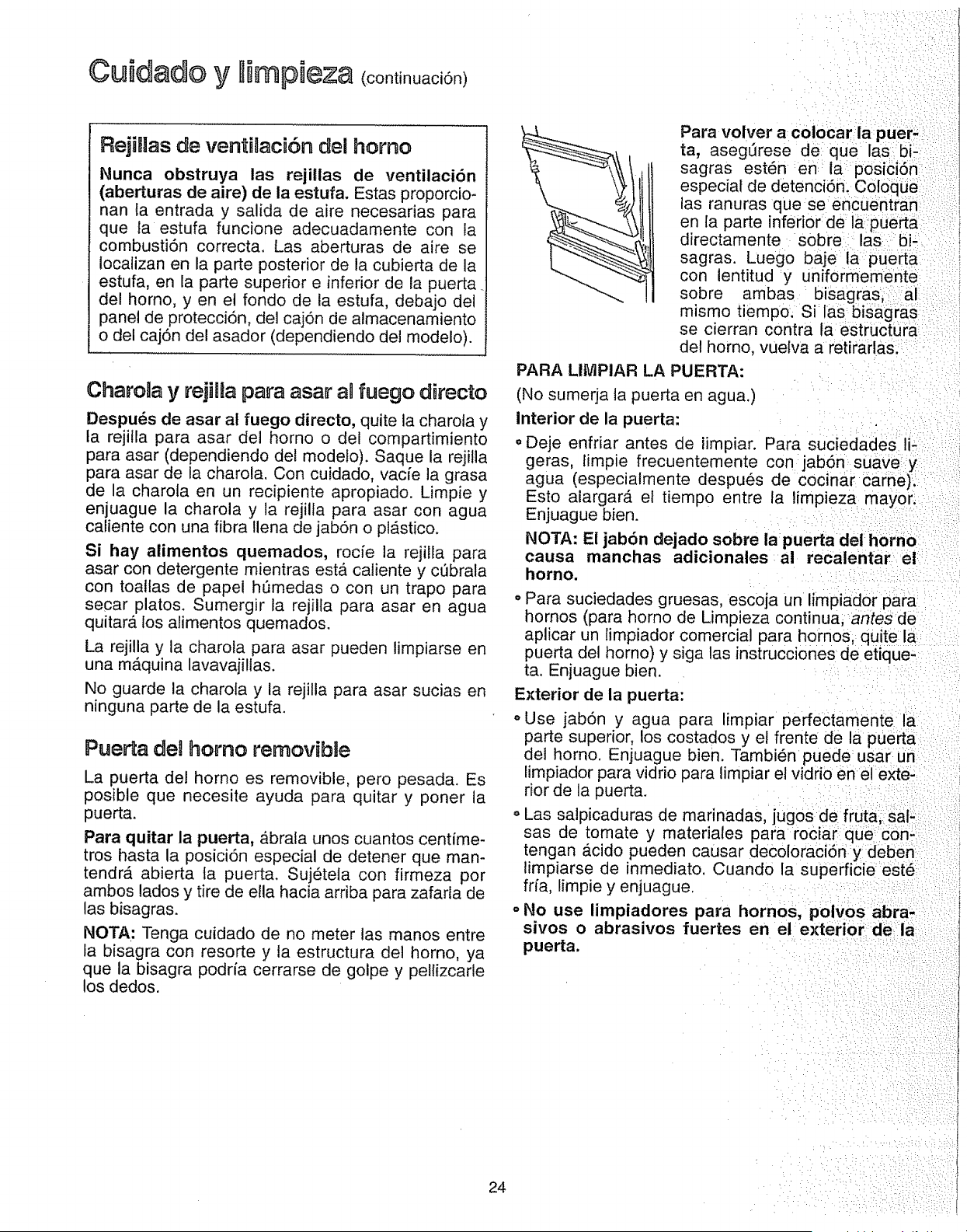
¢uidado y impieza (contnuac6n)
RejiHas de ventilaci6n del homo
Nunca obstruya las rejillas de ventilaci6n
(aberturas de aire) de la estufa. Estas proporcio-
nan la entrada y salida de aire necesarias para
que la estufa funcione adecuadamente con la
combusti6n correcta. Las aberturas de aire se
localizan en la parte posterior de la cubierta de la
estufa, en la parte superior e inferior de la puerta
del homo, yen el fondo de la estufa, debajo del
panel de protecci6n, del caj6n de almacenamiento
o del caj6n del asador (dependiendo del modelo).
CharoMay rejiHapare asar fuego directo
Despu_s de asar al fuego directo, quite la charola y
la rejiila para asar del homo o del compartimiento
para asar (dependiendo del mode[o), Saque la rejiila
para asar de la charola. Con cuidado, vacfe la grasa
de la charola en un recipiente apropiado. Limpie y
enjuague la charola y [a rejilla para asar con agua
caliente con una fibra [lena de jab6n o p[Astico.
Si hay alimentos quemados, rode la rejilla para
asar con detergente mientras estcfi catiente y cQbrala
con toallas de papel h_medas o con un trapo para
secar platos. Sumergir la rejilla para asar en agua
quitar_ los alimentos quemados.
La rejilla y la charola para asar pueden limpiarse en
una mAquina lavavajiltas.
No guarde la charola y la rejilla para asar sucias en
ninguna parte de la estufa.
Puerta dei horno removible
La puerta del homo es removible, pero pesada. Es
posible que necesite ayuda para quitar y poner la
puerta.
Para quitar la puerta, &brafa unos cuantos centime-
tros hasta la posici6n especial de detener que man-
tendr#, abierta ia puerta. Suj_tela con firmeza por
ambos lados y tire de ella hacia arriba para zafarla de
las bisagras.
NOTA" Tenga cuidado de no meter las manos entre
la bisagra con resorte y la estructura de1 homo, ya
que la bisagra podda cerrarse de golpe y peltizcarle
los dedos.
especial de detenci
las ranuras que se encue
en la parte inferior de ........
directamente sobre:' biz:i,::: [:
sagras. Luego
con lentitud y uniformemente::::: :i::::
sobre ambas bisagras;:::::a::i::
mismo tiempo, Si:laS:
se cierran contra fa estructura_: ::.i :::
del homo, vuelva a retirarlas.
PARA LIMPIAR LA PUERTA:
(No sumerja la puerta en agua.) ..... .....: ::
Interior de la puerta: .......
o Deje enfriar antes de limpiar. Para
geras, limpie frecuentemente con jab6n: suave y :: i:
agua (especialmente despues de cocinar Carne)i
Esto alargarA et tiempo entre la [impieza
Enjuague bien.
NOTA: El jab6n dejado sobre la puerta del :hor:no: : :i
causa manchas adicionales al recalentar el: il
homo. :i ::
° Para suciedades gruesas, escoja un limpiador para
hornos (para homo de Limpieza continua, antes de :
aplicar un limpiador comercial para hornos, quite la: ....
puerta del homo) y siga las instrucciones de etique-
ta. Enjuague bien.
Exterior de la puerta:
o Use jab6n y agua para limpiar perfectamente la
parte superior, los costados y el frente de la puerta
del homo. Enjuague bien. Tambi_n puede usar un
limpiador para vidrio para limpiar el vidrio enel exte-
rior de la puerta.
o Las salpicaduras de marinadas, iug0s de fruta, saF
sas de tomate y materiales para rociar que:c0m
tengan _.cido pueden causar decoloraci6n y deben
limpiarse de inmediato. Cuando la superficie est_
frfa, limpie y enjuague
o No use limpiadores para hornos, polvos abra_
sivos o abrasivos fuertes en el exterior dela:
puerta.
24
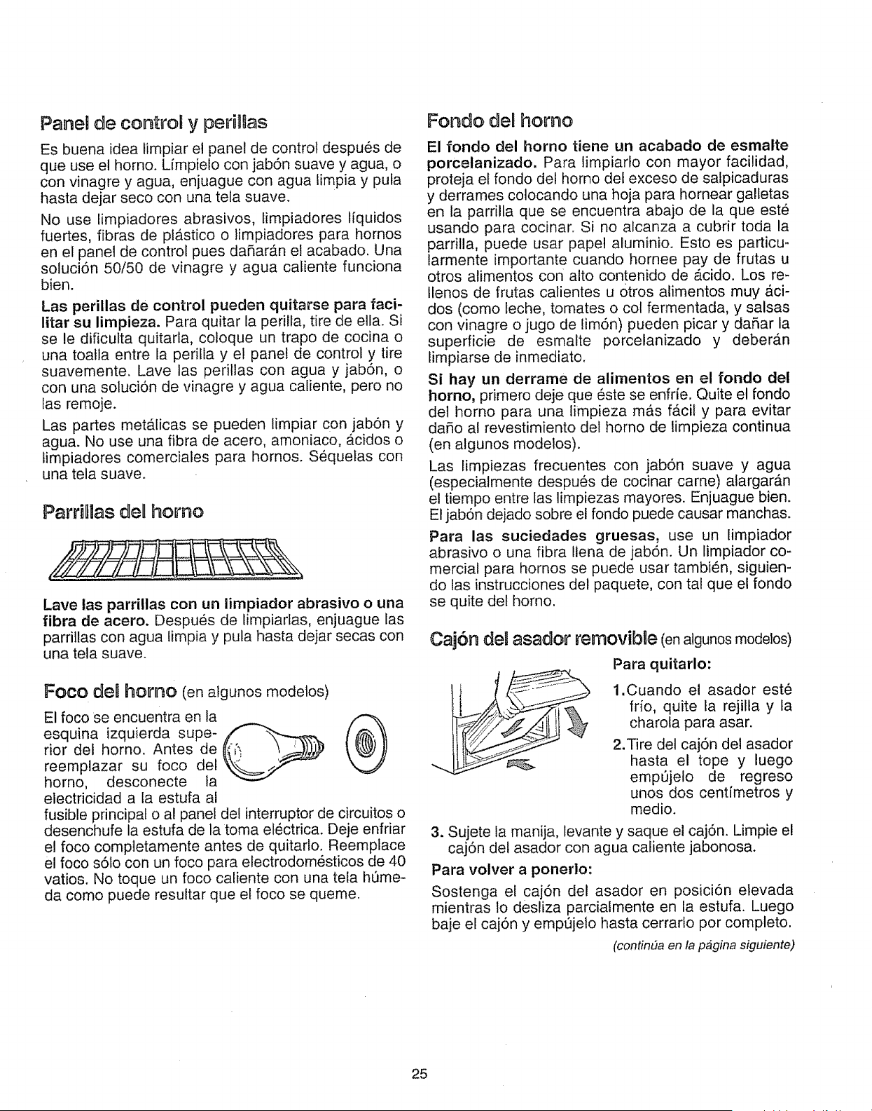
Panel de controU y perH as
Es buena idea limpiar el panel de control despues de
que use el horno. L[mpielo con jab6n suave y agua, o
con vinagre y agua, enjuague con agua fimpia y pula
hasta dejar seco con una tela suave.
No use limpiadores abrasivos, fimpiadores lfquidos
fuertes, fibras de pl_.sfico o timpiadores para hornos
en el panel de control pues daSar_.n et acabado. Una
soluci6n 50/50 de vinagre y agua caliente funciona
bien.
Las perillas de control pueden quitarse para faci-
litar su limpieza. Para qukar la perilla, tire de ella. Si
se le dificutta quitarla, coloque un trapo de cocina o
una toalla entre la perilla y el panel de control y tire
suavemente. Lave las perillas con agua y jab6n, o
con una solucion de vinagre y agua caliente, pero no
las remoje.
Las partes met_licas se pueden limpiar con jabSn y
agua. No use una fibra de acero, amoniaco, acidos o
limpiadores comerciales para hornos. S_quelas con
una tela suave.
ParrJHas deRhomo
Lave las parrillas con un limpiador abrasivo o una
fibra de acero. Despu_s de limpiarlas, enjuague las
parrillas con agua timpia y pula basra dejar secas con
una tela suave.
Foco deB homo (enalgunos modetos)
El foco se encuentra en ta
esquina izquierda supe-
rior del homo. Antes de
reemplazar su foco del
homo, desconecte ta
electricidad a la estufa al
fusible principal o a! panel del interruptor de circuitos o
desenchufe la estufa de la toma ef_ctrica. Deje enfriar
el foco completamente antes de quitarlo. Reemptace
el foco s6lo con un foco para efectrodomesticos de 40
vatios. No toque un foco caliente con una tela hL_me-
da como puede resultar que et foco se queme.
Fondo deR homo
El fondo del horno tiene un acabado de esmalte
porcetanizado. Para limpiarlo con mayor facilidad,
proteja el fondo del homo del exceso de salpicaduras
y derrames colocando una hoja para hornear galletas
en la parrilla que se encuentra abajo de la que est6
usando para cocinar. Si no alcanza a cubrir toda la
parrilla, puede usar papel aluminio. Esto es particu*
larmente importante cuando hornee pay de frutas u
otros alimentos con alto contenido de acido. Los re-
!lenos de frutas calientes u otros alimentos muy Aci-
dos (como feche, tomates o col fermentada, y salsas
con vinagre o jugo de lim6n) pueden picar y dafiar la
superficie de esmalte porcelanizado y deberAn
limpiarse de inmediato.
Si hay un derrame de alimentos en el fondo del
homo, pdmero deje que _ste se enfrie. Quite el rondo
del homo para una limpieza mas f_.cil y para evitar
dafio al revestimiento del homo de limpieza continua
(en algunos modelos).
Las limpiezas frecuentes con jab6n suave y agua
(especialmente despues de cocinar came) alargar_.n
el tiempo entre las limpiezas mayores. Enjuague bien.
El jab6n dejado sobre el fondo puede causar manchas.
Para las suciedades gruesas, use un limpiador
abrasivo o una libra llena de jab6n. Un limpiador co-
merciat para hornos se puede usar tambi_n, siguien-
do las instrucciones det paquete, con tal que el fondo
se quite del homo.
Caj6n det asador removible (enalgunosmodelos)
Para quitarlo:
frio, quite la rejilla y la
charola para asar.
2.Tire del caj6n del asador
_ hasta el tope y luego
emp_jelo de regreso
unos dos cent[metros y
medio.
3. Sujete la manija, levante y saque el caj6n. Limpie el
caj6n del asador con agua caliente jabonosa.
Para volver a ponerio:
Sostenga el caj6n del asador en posici6n etevada
mientras 1o desliza parcialmente en la estufa. Luego
baje el cajdn y empt_jelo hasta cerrarto por completo.
(continDa en la pagina siguiente)
25
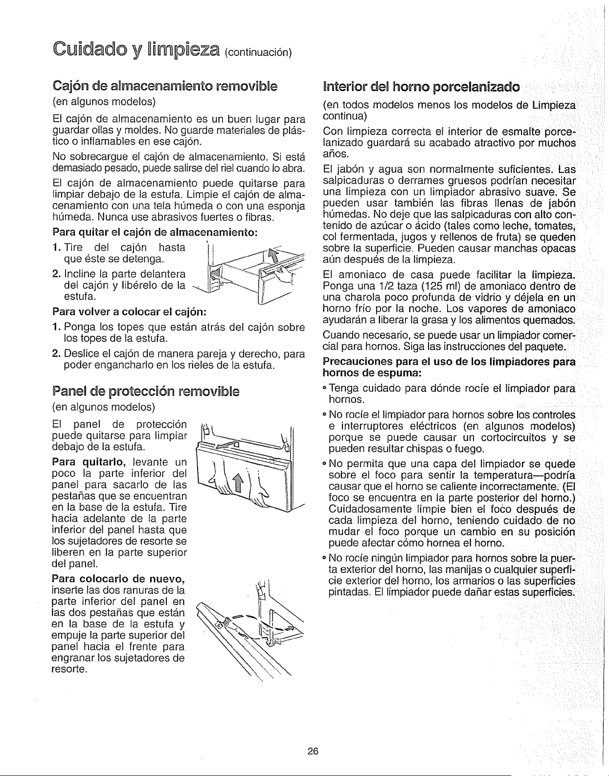
Cuidado y limpieza tcoot ooao n)
Caj6n de almacenarniento rernovibae
(en algunos modelos)
El caj6n de almacenamiento es un buen lugar para
guardar ollas y motdes. No guarde materiaies de plAs-
tico o inflamables en ese caj6n.
No sobrecargue et caj6n de atmacenamiento. Siesta
demasiado pesado, puede salirse del riel cuando to abra.
El caj6n de almacenamiento puede quitarse para
limpiar debajo de la estufa. Limpie el caj6n de alma-
cenamiento con una teta hQmeda o con una esponja
ht]meda. Nunca use abrasivos fuertes o fibras.
Para quitar el caj6n de almacenamiento:
1.Tire de, caj6n hasta 'i __
que este se detenga. __.._...
2. incline ta parte detantera
del caj6n y lib_relo de la
estufa. @_<
Para volver a colocar el cajon:
1. Ponga los topes que est_.n atrAs del caj6n sobre
los topes de la estufa.
2. Deslice el caj6n de manera pareja y derecho, para
poder engancharlo en los deles de la estufa.
PaneUde protecci6n removibMe
(en algunos modeios)
El panel de protecci6n
puede quitarse para limpiar
debajo de la estufa.
Para quitarlo, levante un
poco la parte inferior det
panel para sacarlo de las
pestaSas que se encuentran
en ia base de ia estufa. Tire
hacia adelante de la parte
inferior del panel hasta que
los sujetadores de resorte se
liberen en la parte superior
del panel.
Para colocarto de nuevo,
inserte las dos ranuras de la
parte inferior del panel en
las dos pestaSas que estAn
en la base de ia estufa y
empuje la parte superior dei
panel hacia et frente para
engranar los sujetadores de
resorte.
/
anterior del homo porcelanizado
(en todos modelos menos los modelos de Limpieza
continua)
Con limpieza correcta el interior de esmalte porce-
lanizado guardarb, su acabado atractivo por muchos
aSos.
El jab6n y agua son normalmente suficientes. Las
safpicaduras o derrames gruesos podrfan necesitar
una limpieza con un limpiador abrasivo suave. Se
pueden usar tambi_n las fibras Ilenas de jab6n
hQmedas. No deje que tas salpicaduras con alto con-
tenido de azt_car o acido (tales como leche, tomates,
col fermentada, jugos y rellenos de fruta) se queden
sobre la superficie. Pueden causar manchas opacas
aQn despu#s de ia iimpieza.
Et amoniaco de casa puede facilitar la limpieza.
Ponga una 1/2 taza (125 mt) de amoniaco dentro de
una charola poco profunda devidrio y d_jela en un
homo fifo por la noche. Los vapores de amoniaco
ayudarAn a liberar la grasa y los alimentos quemados,
Cuando necesario, se puede usar un limpiador comer-
ciat para hornos. Siga las instrucciones del paquete.
Precauciones para el uso de los limpiadores para
hornos de espuma:
=Tenga cuidado para d6nde rocie el limpiador para
hornos.
o No rode el limpiador para hornos sobre los controles
e interruptores el_ctricos (en algunos modelos)
porque se puede causar un cortocircuitos y se
pueden resultar chispas o fuego.
o No permita que una capa del impiador se quede
sobre el foco para sentir la temperatura--podria
causar que el homo se caliente incorrectamente. (El
foco se encuentra en la parte posterior del horno.)
Cuidadosamente limpie bien el foco despu_s de
cada limpieza del homo, teniendo cuidado: de no
mudar el foco porque un cambio en su posici6n
puede afectar c6mo hornea el horno.
o No rode ningQn limpiador para hornos sobre la puer-
ta exterior del homo, las manijas o cualquier superfi-
cie exterior del homo, los armarios o las superficies
pintadas. El limpiador puede daSar estas superficies:
26
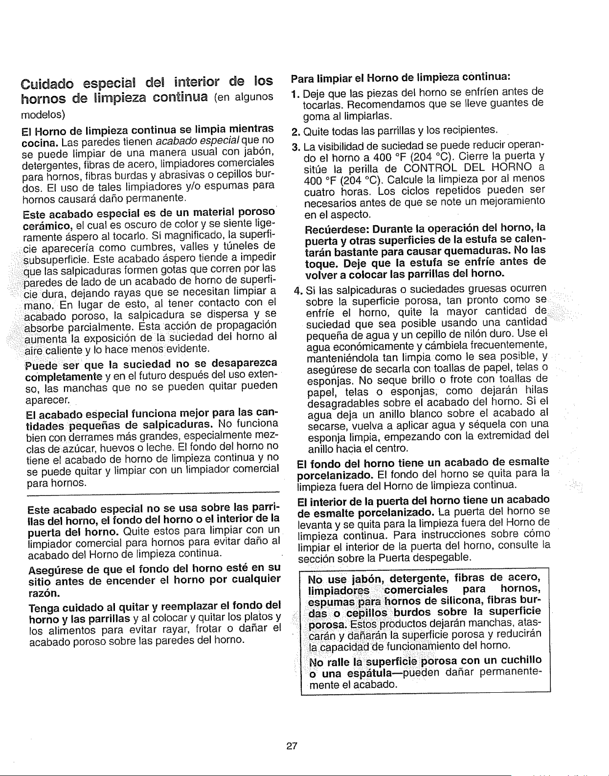
Cuidade especial dei interior de tes
hornos de Rirnpieza continua (en algunos
modelos)
El Horno de limpieza continua se limpia mientras
cocina. Las paredes tienen acabado especial que no
se puede limpiar de una manera usual con jabSn,
detergentes, fibras de acero, limpiadores comerciales
para hornos, fibras burdas y abrasivas o cepillos bur-
dos. El uso de tales limpiadores yio espumas para
hornos causar_ dafio permanente.
Este acabado especial es de un material poroso
cer_mico, el cual es oscuro de color y se siente lige-
ramente _.spero at tocarlo. Si magnificado, la superfi-
i:cie apareceda como cumbres, valles y t_neles de
: i_i!:subsuperficie. Este acabado aspero tiende a impedir
_: :que las salpicaduras formen gotas que corren por las
,_:i:,iparedes de lado de un acabado de homo de superfi-
:::ciei:dura, dejando rayas que se necesitan limpiar a
:mano, En lugar de esto, al tener contacto con el
::(iacabado poroso, la salpicadura se dispersa y se
:i:iabS0rbe parcialmente. Esta acci6n de propagaci6n
i_i i:_iaulmenta la exposici6n de la suciedad del homo al
':i::::iairecaliente y Io hace menosevidente.
la suciedad no se desaparezca
completamente yen el futuro despu_s del uso exten-
so, las manchas que no se pueden quitar pueden
aparecer.
El acabado especial funciona mejor para las can-
tidades pequefias de salpicaduras. No funciona
bien con derrames mb,s grandes, especialmente mez-
clas deazecar, huevos o leche. El fondo del homo no
tiene el acabado de homo de limpieza continua y no
se puede quitar y limpiar con un limpiador comercial
para hornos.
Este acabado especial no se usa sobre las parri-
Ilas del homo, el fondo del homo o el interior de la
puerta del homo. Quite estos para limpiar con un
limpiador comercial para hornos para evitar dafio al
acabado del Homo de limpieza continua.
Aseg_rese de que el rondo del homo est_ en su
sitio antes de encender el homo por cualquier
razbn.
Tenga cuidado al quitar y reemplazar el fondo del
homo y las parrillas y al colocar y quitar los platos y
los alimentos para evitar rayar, frotar o dafiar el
acabado poroso sobre las paredes del horno.
Para iimpiar el Homo de limpieza continua:
1. Deje que las piezas det homo se enfrien antes de
tocarlas. Recomendamos que se Ileve guantes de
goma al limpiarlas.
2. Quite todas las parrillas y los recipientes.
3. La visibilidad de suciedad se puede reducir operan-
do el homo a 400 °F (204 °C). Cierre la puerta y
sitQe la perilla de CONTROL DEL HORNO a
400 °F (204 °C). Calcule la limpieza por al menos
cuatro horas. Los ciclos repetidos pueden ser
necesarios antes de que se note un mejoramiento
en el aspecto.
Rect_erdese: Durante la operacibn del homo, la
puerta y otras superficies de la estufa se calen-
tar,_n bastante para causar quemaduras. No las
toque. Deje que la estufa se enfrie antes de
volver a colocar las parriilas del horno.
4, Si las salpicaduras o suciedades gruesas ocurren
sobre ta superficie porosa, tan pronto como se :i
enfrie el homo, quite la mayor cant dad de: ::
suciedad que sea posible usando una cantidad :'_:_::::::
pequefia de agua y un cepillo de nil6n duro. Use et
agua econ6micamente y c_mbiela frecuentemente,
manteni_ndola tan limpia:como le sea posibte, y
asegerese de secarla contoattas de papel, telas o
esponjas. No seque brillo o frote con toatlas de
papel, telas o esponjas; como dejaran hilas
desagradables sobre el acabado del horno. Si el
agua deja un anillo blanco sobre el acabado a!
secarse, vuelva a aplicar agua y sequela con una
esponja limpiat empezando con la extremidad det
anillo hacia el centro.
El fondo del horno tiene un acabado de esmalte
porcelanizado. El fondo del homo se quita para la
limpieza fuera del Homo de limpieza continua.
El interior de la puerta del homo tiene un acabado
de esmalte porcelanizado. La puerta del horno se
levanta y se quita para la limpieza fuera del Homo de
limpieza continua. Para instrucciones sobre c6mo
limpiar el interior de la puerta det homo, consulte ta
secci5 n sobre la Puerta despegable.
Nouse " detergente, fibras de acero,
!impia d comerciales para hornos,
los de silicona, fibras bur-
:burdos sobre la superficie
dejaran manchas, atas-
superficie porosa y reducir_n
_iSha:miento del homo.
27
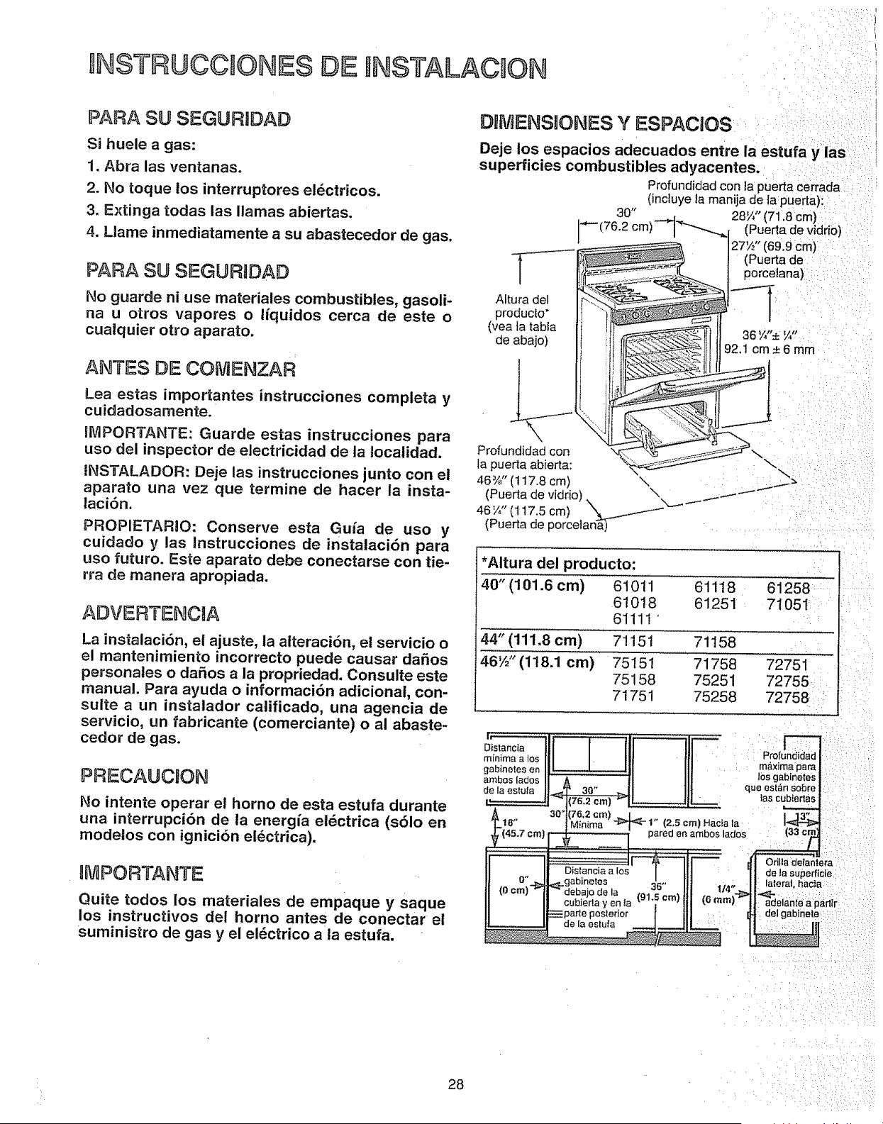
BNSTRUCC ONES DE NSTALAC ON
PARA SU SEGURtDAD
Si huele a gas:
1. Abra las ventanas.
2. No toque los interruptores el_ctricos,
3. Extinga todas las llamas abiertas.
4. Llame inmediatamente a su abastecedor de gas.
PAIRA SU SEGURJDAD
No guarde ni use materiales combustibles, gasoli,
na u otros vapores o liquidos cerca de este o
cuaiquier otto aparato.
ANTES DE CO_/IENZAR
Lea estas importantes instrucciones completa y
cuidadosamente.
IMPORTANTE: Guarde estas instrucciones para
uso del inspector de electricidad de la Iocalidad.
INSTALADOR: Deje las instrucciones junto con el
aparato una vez que termine de hacer la insta-
laci6n.
PROPIETARIO: Conserve esta Guia de uso y
cuidado y las lnstrucciones de instalacibn para
uso futuro. Este aparato debe conectarse con tie-
rra de manera apropiada.
ADVERTENCaA
La instalaci6n, el ajuste, la alteraci6n, el servicio o
el mantenimiento incorrecto puede causar daSos
personales o daSos a la propriedad. Consulte este
manual. Para ayuda o informacibn adicional, con-
suite a un instalador calificado, una agencia de
servicio, un fabricante (comerciante) o al abaste-
cedor de gas.
PRECAUCHON
No intente operar el horno de esta estufa durante
una interrupci6n de la energia el6ctrica (s61o en
modetos con ignicibn el_ctrica).
Bh'_PORTANTE
Quite todos los materiales de empaque y saque
los instructivos del horno antes de conectar el
suministro de gas y el el6ctrico a la estufa.
DIMENSJONES Y ESPACiOS
Deje los espacios adecuados entre la estufa y las
superficies combustibles adyacentes.
Profundidad con la puerta cerrada
(incluye Jamanija de ta puerta):
30" 28W' (71.8 cm)
_--(76.2 cm)--'l_-.._ (P,uertadevidrio)
27½ (69.9 Cm)
[I (Puerta de
porcelana)
Altura del
producto"
(yea la tabla
de abajo)
_
Profundidad con
la puerta abierta:
36 W'± 'A"
92.1 cm ± 6 mm
46%" (117.8 cm) \\ _._____....._._- _
(Puerta de vidfio). X_....__
46 V,,"(t 17.5 cm)
(Puerta de porcetan_)
*Altura del producto:
40" (101.6 cm) 61011 61118 61258
61018 61251 71051
61111 '
44"(111.8 cm) 71151 71158
46½"(118.1 cm) 75151 71758 72751
75158 75251 72755
71751 75258 72758
, F--
istancta Profundidad
ifnima a los m_ixirna para
abinetes en 10s gabinetes
mbes lados
que estan sobre
e la estufa
las cubiedas
. - - (76.2cm) _ -,, ,
30" (76.2 cm)
t le" Minima ,_"_-1" (2.5 cm) Hac I_
.i-(4_'7_) .j_ .q p_,ode,,ambo, (33_,
/
" " _ /_t Orilta de{antera
Distancla a los / de ta superficle :
lateral, hacia
0" _gabinetes 36"
(0 cm) -_ _debaj0 de la 191 5 cm', 1
adelanle a
cubierla yea Ia ' *l ' (6 rr -,4_,
___parle poslerior |
de la estufa .--.4 _ :
28
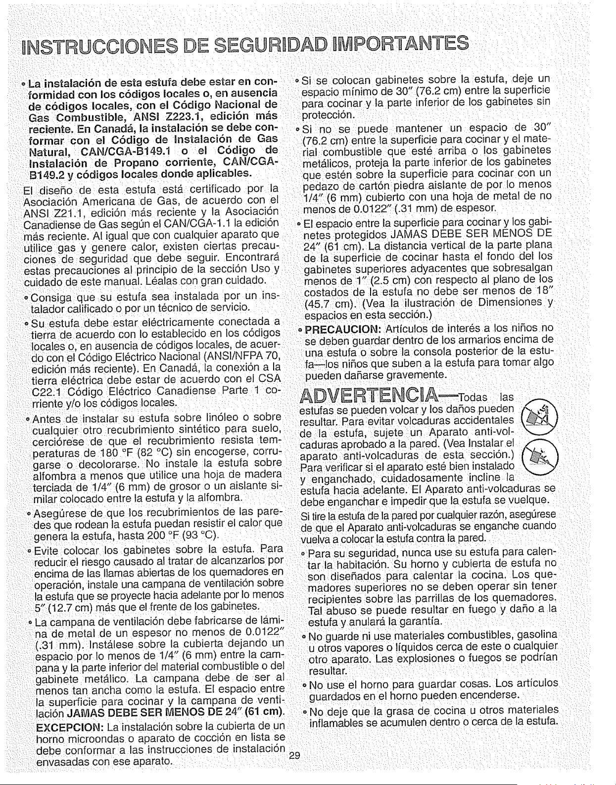
INSTRUOOtONES BE SEQUIRIDAD !I IPORTANTES
o La instalaci6n de esta estufa debe estar en con-
:formidad con los c6digos locales o, en ausencia
de:c6digos locales, con el C6digo Nacional de
Gas Combustible, ANSI Z223.1, edici6n m&s
reciente. En Canada, la instalaci6n se debe con-
format con el C6digo de Instataci6n de Gas
Natural, CAN/CGA-B149.1 o el C6digo de
tnstalacion de Propano corriente, CAN/CGA-
18149.2 y c6digos locales donde aplicables.
El disefio de esta estufa esta certificado por la
Asociaci6n Americana de Gas, de acuerdo con el
ANSI Z21.1, edici6n :m&s reciente y la Asociaci6n
Canadiense de Gas seg0n el CAN/CGA-1.1 ta edici6n
m&s reciente. AI igual que con cualquier aparato que
uti!ice gas y genere calor, existen ciertas precau-
Clones de seguridad que debe seguir. Encontrar&
estas precauciones al principio de ta secci6n Uso y
cuidado de este manual. L6alas con gran cuidado.
_Consiga que su estufa sea instalada por un ins-
talador calificado o por un tecnico de servicio.
Su estufa debe estar electricamente conectada a
tierra de acuerdo con Io establecido en los c6digos
locates o, en ausencia de c6digos locales, de acuer-
do con el C6digo Et_ctrico Nacional (ANSi/NFPA 70,
edici6n mb,s reciente). En Canadb,. la conexion a la
tierra electrica debe estar de acuerdo con el CSA
C22;I C6digo Etectrico Canadiense Parte l co-
rriente y/o los c6digos locales.
°Antes de instalar su estufa sobre lin6teo o sobre
cualquier otro recubrimiento sintetico para suelo,
oSi:se colocan gabinetes sobre la estufa, deje un
espacio minimo de 30" (76.2 cm) entre ia superficie
para cocinar y la parte inferior de los gabinetes sin
proteccion.
o Si no se puede mantener un espacio de 30"
(76.2 cm) entre la superficie para cocinar y el mate-
rial combustible que este arriba o los gabinetes
metalicos, proteja la parte inferior de los gabinetes
que esten sobre la superficie para cocinar con un
pedazo de cart6n piedra aislante de por lo menos
1i4" 6 ram) cubierto con una hoja de meta de no
menos de 0.0t22" (.31 mm) de espesor.
o El espacio entre la superficie para cocinar y los gabi-
netes protegidos JAMAS DEBE SER MENOS DE
24'_ (61 cm), La distancia vertical de ta parte plana
de la superficie de cocinar hasta el fondo del los
gabinetes superiores adyacentes que sobresalgan
menos de 1" (2.5 cm) con respecto al piano de los
costados de la estufa no debe set menos de 18"
(45.7 cm).: (Yea la ilustraci6n de Dimensiones y
espacios en esta secci6n.)
oPRECAUClON: Articulos de interes a los niSos no
se deben guardar dentro de los armarios encima de
una estufa o sobre la consola posterior de ia estu-
faz-los nifios que suben a la estufa para tomar algo
pueden dafiarse gravemente.
ADV ERTE N OUA="Todas las
estufas se pueden volcar y los daflos :pueden /",,_"_
resultar. Para evita r volcaduras accidentales
de la estufa, sujete:un Aparato anti-vol-
cerciorese de queoFel recubrimientOoc) resista tern- Cpd_ar_s _PnrtObvadOa_p a c_d. (eVs_a!_lstlarne I
peraturas de180 (82 sin encogerse, co_u- r
garse o decoiorarse. ;:r4o.,insl:ale :_oleSduTaadere Para:verificar si el aparato este bien instalado
alfombra a menos que uu_ ce una j
..... . v enganchado; cuidadosamente nc ne ta
terciada de 1t4" (6 mm) de grosor o un aisiame si-
estufa hacia adelante. El Aparato anti-volcaduras se
milar colocado entre la estufa y la alfombra.
oAseg_rese de que los recubrimientos de las pare:
des que rodean ta estufa puedan resistir el calor que
:genera la estufa, hasta 200 °F (93 °C).
_Evite colocar los gabinetes sobre la estufa. Para
reducir el riesgo causado al tratar de alcanzartos por
encima de las Ilamas abiertas de los que madores en
operaci6n, instale una campana de ventilacion sobre
la estufa que se proyecte hacia adelante por Io menos
5" (12.7 cm)mas que e! frente de los gabinetes.
o La campana de ventilaci6n debe fabricarse de I_tmi-
na de metal de un espesor no menos de 0.0122"
:(.31 mm)_ lnstb, lese sobre la cubierta dejando un
espacio por lo menos de 114" (6 mm) entre la cam-
pana y la parte inferior del material combustible o del
gabinete metAlico. La campana debe de ser al
menos tan ancha como la estufa, El espacio entre
la superficie para cocinar y ta campana de venti-
laci6n JAMAS DEIBE SER IVIENOS DE 24" (61 cm).
EXCEPCION: La :instalaci6n sobre la cubierta de un
homo microondas o aparato de coccion en lista se
debe conformar a las instrucciones de instalaci6n
envasadas con ese aparato.
debe enganchar e impedir que la estufa se vuelque.
Si tire }a estufa de la pared pot cualquier raz6n, asegQrese
de que el Aparato anti-v01caduras se enganche cuando
Vuel_ia a colocar la estufa contra la pared.
:_Para su seguridad, nunca use su estufa para calen-
tar:la habitaci6n. :Su homo y cubierta de estufa no
son disefiados para calentar ta cocina. Los que-
madores superiores no se deben operar sin tener
recipientes sobre las parrillas de los quemadores_
Tal abuso se puede resultar en fuego y dafio a la
estufa y anular_t la garantia.
oNo guarde ni use materiales combustibles, gasolina
u otros vapores o I!quidos cerca de este o cualquier
otro aparato. Las exptosiones o fuegos se podrian
resultar.
o No use el homo para guardar cosas. Los articulos
guardados en el homo pueden encenderse.
oNo deje que la grasa de cocina u otros materiales
inflamables se acumulen dentro o cerca de la estufa.
29
nstrucc6ones de instaiacU6n
GENERALIDADES
o Consulte los datos relativos a las dimensiones y
espacios en esta secci6n para conocer las dimen-
siones para empotrar y los espacios requeridos.
Estas dimensiones deben satisfacerse de modo que
usted tenga un uso seguro de su estufa. La Ioca-
lizaci6n de ta toma de cordente el_ctrica y de la
abertura para el tubo de gas (vea Localizaci6n del
tubo de gas y de la toma de corriente)pueden ajus-
tarse para satisfacer los requerimientos especfficos.
=La estufa puede colocarse sin dejar .espacio
[0" (0 cm)] atr_.s (empotrada) contra la parte poste-
rior y los costados de ta estufa.
COLOCACeON
No coloque la estufa donde pueda estar sujeta a co-
rrientes de aire fuertes. Cualesquiera aberturas en el
suelo o en la pared detrAs de la estufa deberAn se-
flarse. Asegt]rese de que las aberturas alrededor de la
base que proporcionan aire fresco para la combusti6n
y la ventilaci6n no se encuentren obstruidas por
alfombra o madera.
PROTEJA SU SUELO
Su estufa, como muchos otros aparatos elec-
trodomesticos, es pesada y puede colocarse en
recubrimientos suaves para suelo, tales como vinilo
acolchonado o alfombra. Tenga cuidado cuando
mueva la estufa en este tipo de suelo. Se recomienda
seguir las instrucciones sencillas y econ6micas a con-
tinuaci6n para proteger su piso.
La estufa debe instalarse sobre una hoja de madera
terciada (o de un material similar). Cuando el
recubrimiento del suelo termine en ta parte delantera
de la estufa, el _.rea sobre la que descansarA la estufa
deber_, fabricarse con madera terciada al mismo nivel
o un poco mAs arriba que e! recubnmiento del suelo.
Esto permitir_ que la estufa pueda moverse para
limpiarla o darle servicio_
LOCALIZACION DEL MODELO Y DEL
NUMERO DE SERtE ....
i
Dependiendo de su estufa, encontrarA el modelo y los
numeros de serie en una etiqueta en la parte
delantera de la estructura, detrAs del caj6n de alma-
cenamiento, del caj6n del asador o del panel de pro-
tecci6n.
HERRAMUENTAS
o Destornilladores pfanos y Phillips iii:ii:::i i:::i::::
• Un tApiz y una regia
de gas. :: ::iii::
o Sellador para tuberia o una cinta adhesiva para: tub0
aprobada por la UL con Teflon*, que resista la acci_Sn ..........
de los gases naturales y LP.
o Extensi6n de tubo flexible metai [i
Se recomienda un tubo de 5' (1.5
una instalaci6n m,_s fAci!, aunque
tambi_n son aceptables.
viejo cuando instale una estufa:nueva::: ::i::::: :
:
o Adaptador de uni6n para conectar a iatUberia:
mentaci6n o suministro de gas [3/4'_"or:1/2":
y presibn normal) x 1/2" (diAmL nt_)]. :
o Adaptador de uni6n para conectar al reg,
presi6n sobre la estufa [t/2" (tempi y presi6nno:r-
maf) x 1/2" (diAm. int.)]. ................................... .........*Teflon: marca registrada de Du Pont i :i::i
PREPARAC,ON iii ::i:::i ::_:
°Qu tetodalac ntaadhes ,,ay ernp quei:Le a te........
fa cubierta (en los modelos con quemadOreS duales
y retire cualquier material de empaque
encuentre debajo. Asegerese:
madores duales est_n
nivelados.. :=:i
o Quite la pelfcula pl_stfca que
cromadas (la puerta del homo, el
dos). :: =ii:
o Saque la bolsa de accesorlos que
el homo. :: :: i
° aevisela para asegurarsede q:ui:'
partes de la estufa se hayan
traslado.
3O
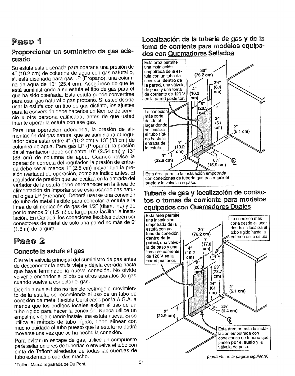
Paso
Proporcionar un suministro de gas ade-
cuado
Su estufa esta dise5ada para operar a una presi6n de
4" (10.2 cm) de columna de agua con gas natural o,
si, estA diseRada para gas LP (Propano), una colum-
na de agua de 10" (25.4 cm). Asegt)rese de que le
esta suministrando a su estufa el tipo de gas para el
que ha sido diseRada. Esta estufa puede convertirse
para usar gas natural o gas propano. Si usted decide
usar la estufa con un tipo de gas distinto, los ajustes
para ta conversiSn debe hacerlos un t_cnico de servi-
cio u otra persona calificada, antes de que usted
intente operar la estufa con ese gas.
Para una operaci6n adecuada, la presi6n de ali-
mentaci6n del gas natural que se suministra al regu-
tador debe estar entre 4" (I0.2 cm) y 13" (33 cm) de
columna de agua. Para gas LP (Propano), la presi6n
de alimentaci6n debe ser entre 10" (2.54 cm) y 13"
(33 cm) de columna de agua. Cuando revise la
operaci6n correcta del regulador, la presi6n de entra-
da debe ser al menos 1" (2.5 cm) mayor que la pre-
siSn (variada) de operaci6n, como se indic6 antes. El
regulador de presi6n que se localiza en la entrada del
variador de la estufa debe permanecer en la linea de
alimentaci6n sin importar si se esta usando gas natu-
ral o gas LP (Propano). DeberA usarse una conexi6n
de tubo de metal flexible para conectar la estufa a la
linea de alimentaci6n de gas de 112" (diAm. int.) y de
por Io menos 5' (1.5 m) de largo para facilitar fa insta-
laci6n. En CanadA, los conectores flexibles deben ser
conectores de metal de s61o una pared no m_s de 6"
(! .8 m) de largura.
Paso 2
Conecte Baestufa al gas
Cierre la v#,lvula principal def suministro de gas antes
de desconectar la estufa vieja y dejeia cerrada hasta
que haya terminado la nueva conexi6n. No olvide
volver a encender el pitoto de otros aparatos de gas
cuando vuelva a conectar el gas.
Debido a que el tubo no flexible restringe el movimien-
to de la estufa, se recomienda el uso de un tubo de
conexi6n de metal flexible Certificado por la A.G.A. a
menos que los c6digos locales exijan el uso de un
tubo rigido para hacer la conexi6n. Nunca utilice un
empalme viejo cuando instale una estufa nueva. Si se
utitiza el m_todo de tubo rfgido, debe alinear con
mucho cuidado el tubo puesto que la estufa no podra
moverse una vez que se ha hecho la conexi6n.
Para evitar un escape de gas, utilice un compuesto
para sellar uniones de tuberias o envuelva el tubo con
cinta de Teflon* alrededor de todas las cuerdas de
tubo externas o cuerdas macho.
*Teflon: Marca registrada de Du Pont.
Locaaizaci6n de la tuberia de gas y de Ba
toma de corriente para modelos equipa-
dos con Quernadores Selnados
Esta Area permite
una instalaci6n
empotrada de la es-
tufa con un tubo de
conexi6n dentro de
ta pared, una v_ivula
i de paso y una toma
de corriente de 120 V
en la pared posterior.
La conext6n
mAs corta
desde el
i lugar donde 2"
se Iocaliza
el tubo rfgi- (5.1 cm)
do hasta la
entrada de
la estufa.
9" 6,_,;-_
(22.9 cm)
(15.9 cm) _=-
I Esta Area permite ta instalaciSn ernpotrada
con conexiones de tuberia que pasen por el
suelo y ta vAtvula de paso.
Tuberia de gas y iocalizacibn de contac-
tos o tomas de corriente para rnode_os
equipados con Quemadores Duales
Esia Area permite
una instalaci6n La conexi6n m_s
empotrada de la corta desde et lugar
estufa con un 30" donde se localiza el
tubo de conexi6n (76.2 cm) tubo rigido basra la
dentro de la 7" entrada de la estufa.
pared, una vAIvu- (17.8
ta de paso y una cm
tomade corriente (10.2
de 120 V en la
pared posterior.
2 _J
cm)
3I
permite ia insta-
laci6n empotrada con
conexiones de tuber[a que
pasen por el suelo y fa
v&Jvula de paso.
(continUa en la pbgina siguiente)
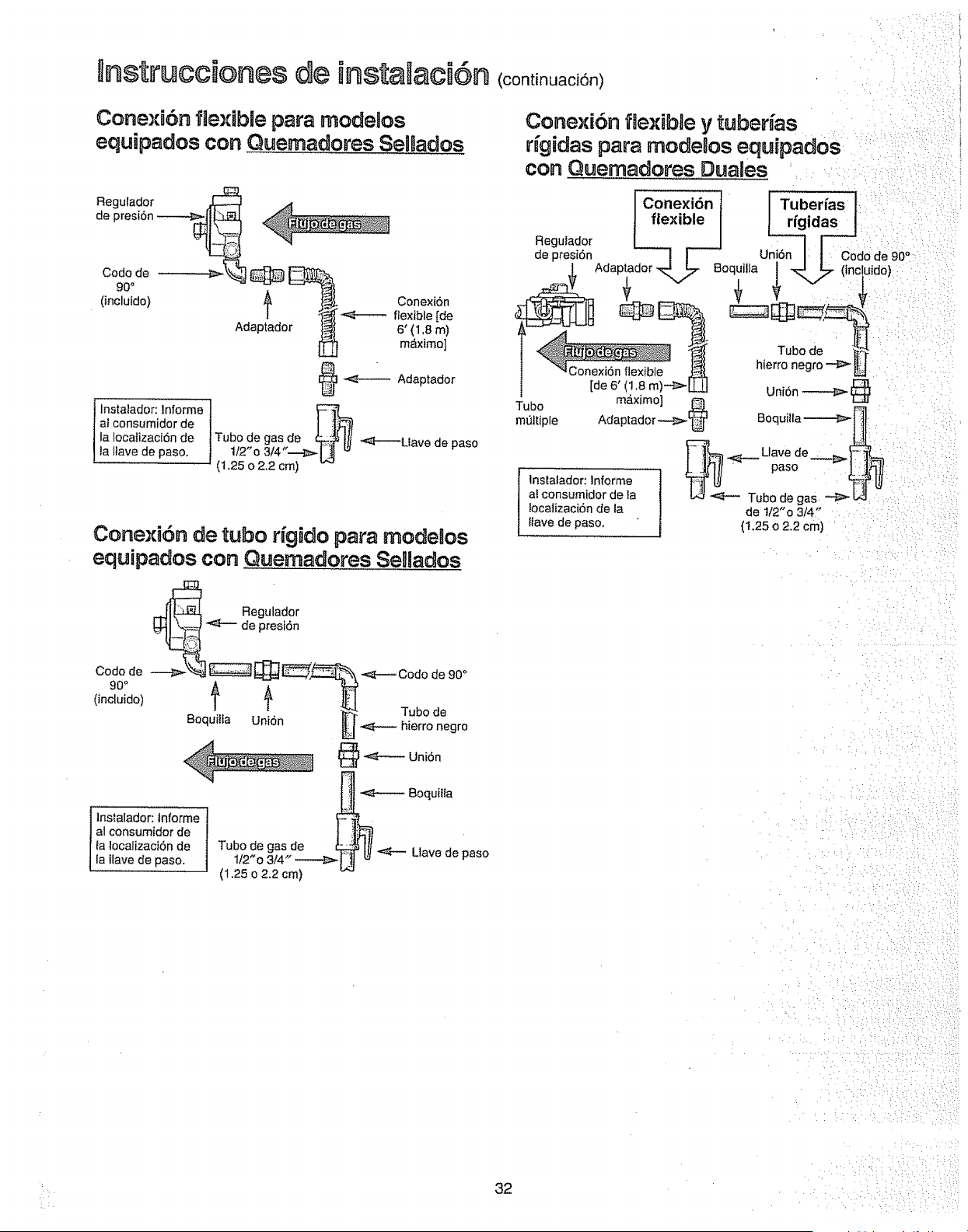
nstrucciones de instalaci6n (coot ouac ,o)
Conexibn flexible para modenos
equipades con Quemaderes SeJBados
Regulador a_
de presi6n __ .
Codode ------_N_ _ _
90° -- T _- _..1
(incluido) _ -_._ ConexiOn
flexible [de
Adaptador 6' (1.8 m)
m_ximo]
@ _----- Adaptador
lnsta]ador: Informe
al consumidor de
la Iocatizacidn de Tubo de gas de _l-----Llave de paso
la ltave de paso. 1/2"o 3!4"----_ L_ _
(1.25 o 2.2 cm)
Conexibn de tubo rigidopara modeaos
equipados con Quemadores SeHados
_,_]_ Regulador
"_-" de presidn
Code de _',-_ _'}e__ _F---Codo de 90 °
(inc_Ouid°) _ { _ Tubo de
Boqullfa Uni6n _I _ hierro
negro
# --uo,0o
N _
Boquiila
lnstalador: lnforme
al consumidor de
lalallavel°Oalizaoi6ndepaso.de Tu_d_ _a4s6e _ [_ _ Uave de paso
(1.25 o 2.2 cm)
Conexibn flexibJe y tuberias
rigidas para modemosequipados
con Quemadores Duales
Conexi6n ] { Tuberias I
flexible r_idasRegulador J
do de 90"
de presi6n ] [ U
(irlc[uido)
hierro negro _
I [de 6' (1.8 Frl)_LL U Uni6n -------1_ _
Tubo m_.ximo] _
mtiltiple Adaptador _ BoquRla--------_--_
_ _._ Llave de__ _
- _- J.(lll " paso ] ]_11
Ins_alador: Informe _F I_ _ UJ
al consumidor de la L2J _ Tubo de gas _ L_
!ocatizaci6n de la de 112"o 314"
ftave de paso. {1.25 o 2.2 cm)
32
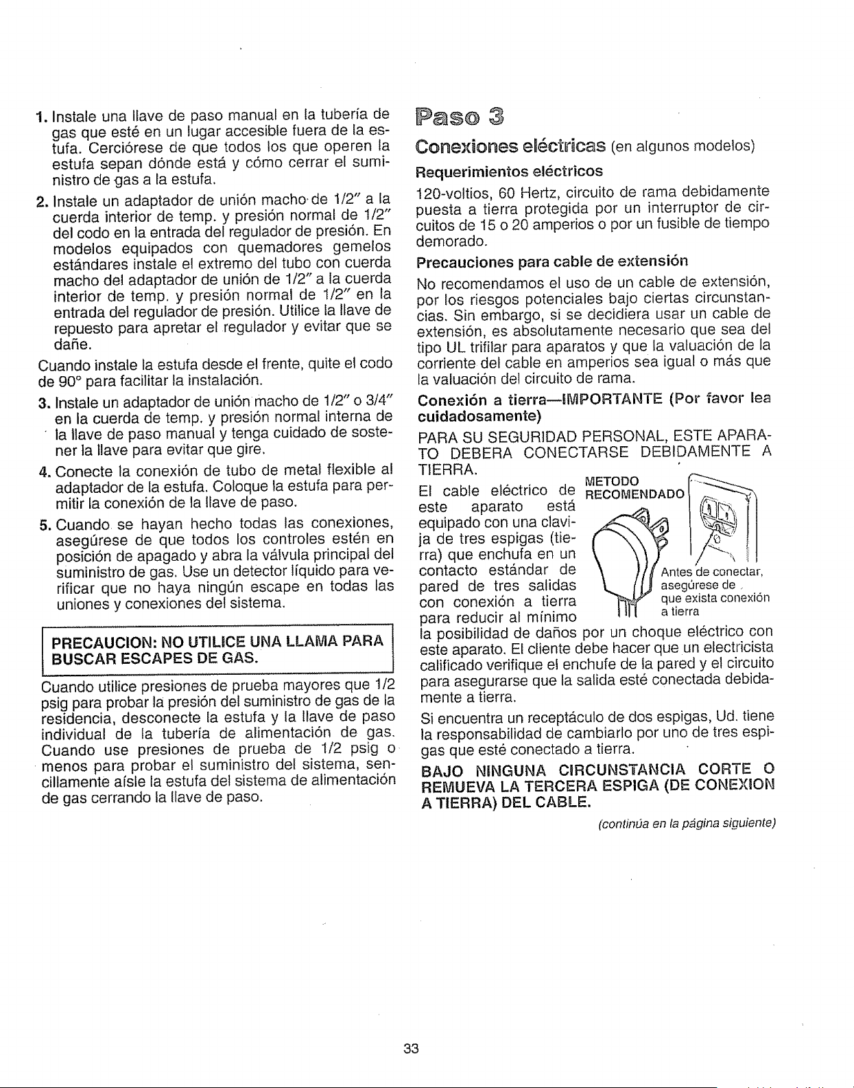
1. Instaleuna Ilavede paso manualen ta tuberiade
gas que est_ en un lugar accesible fuera de la es-
tufa. Cerci6rese de que todos los que operen la
estufa sepan d6nde est& y c6mo cerrar el sumi-
nistro de gas a la estufa.
2. Instale un adaptador de uni6n macho.de 1/2" a la
cuerda interior de temp. y presi6n normal de 1/2"
del codo en la entrada def regulador de presi6n. En
rnodelos equipados con quemadores gemelos
est_.ndares instale el extremo def tubo con cuerda
macho del adaptador de uni6n de 112" a la cuerda
interior de temp. y presi6n normal de 1/2" en la
entrada del regulador de presi6n. Utilice la llave de
repuesto para apretar el regutador y evitar que se
dare.
Cuando instale ta estufa desde el frente, quite el codo
de 90 ° para facilitar la instataci6n.
3. Instale un adaptador de uni6n macho de 1/2" o 3/4"
en la cuerda de temp. y presi6n normal interna de
la Ilave de paso manual y tenga cuidado de soste-
net ta ilave para evitar que gire,
4. Conecte la conexi6n de tubo de metal flexible a!
adaptador de la estufa. Coloque la estufa para per-
mitir la conexi6n de la llave de paso.
5. Cuando se hayan hecho todas las conexiones,
asegOrese de que todos los controles est_n en
posici6n de apagado y abra fa vb.lvula principal del
suministro de gas. Use un detector liquido para ve-
rificar que no haya ningOn escape en todas las
uniones y conexiones del sistema.
PRECAUCION: NO UTILtICE UNA LLAMA PARA
BUSCAR ESCAPES DE GAS.
Cuando utilice presiones de prueba mayores que 1/2
psig para probar la presi6n del suministro de gas de la
residencia, desconecte la estufa y la Ilave de paso
individual de la tuberfa de alimentaci6n de gas.
Cuando use presiones de prueba de 1t2 psig o
menos para probar et suministro del sistema, sen-
cillamente afsle la estufa del sistema de alimentaci6n
de gas cerrando ia ilave de paso.
Pas® :3
Conexiones e ctricas (en algunos modelos)
Requerimientos el_ctricos
120woltios, 60 Hertz, circuito de rama debidarnente
puesta a tierra protegida por un interruptor de cir-
cuitos de 15 o 20 amperios o por un fusible de tiempo
demorado.
Precauciones para cable de extensi6n
No recomendamos el uso de un cable de extensi6n,
por los riesgos potenciates bajo ciertas circunstan-
cias. Sin embargo, si se decidiera usar un cable de
extensi6n, es absolutamente necesario que sea del
tipo UL trifilar para aparatos y que la valuaci6n de la
corriente del cable en amperios sea igual o m_s que
la valuaci6n del circuito de rama.
Conexi6n a tierra--tMPORTANTE (Pot favor lea
cuidadosamente)
PARA SU SEGURIDAD PERSONAL, ESTE APARA-
TO DEBERA CONECTARSE DEBIDAMENTE A
TIERRA.
METODO
El cable etectrico de RECOMENDADOt -""--.,-_
este aparato esta
equipado con una clavi- _--_/'-_
ja de tres espigas (tie-
rra) que enchufa en un
contacto estandar de rites de conectar,
pared de tres salidas L /U asegOresede
con conexi6n a tierra _ queexistaconexi6n
para reducir al minimo I II | a tierra
la posibilidad de daBos por un choque electrico coil
este aparato, El cliente debe hacer que un electricista
calificado verifique el enchufe de la pared y el circuito
para asegurarse que la salida est_ conectada debida-
mente a tierra.
Si encuentra un receptAculo de dos espigas, Ud. tiene
la responsabilidad de cambiarto por uno de tres espi-
gas que est_ conectado a tierra.
BAJO NINGUNA ClRCUNSTANClA CORTE O
REtVIUEVA LA TERCERA ESPIGA (DE CONEXION
A TIERRA) DEL CABLE,
(continda en la pagina siguiente)
33
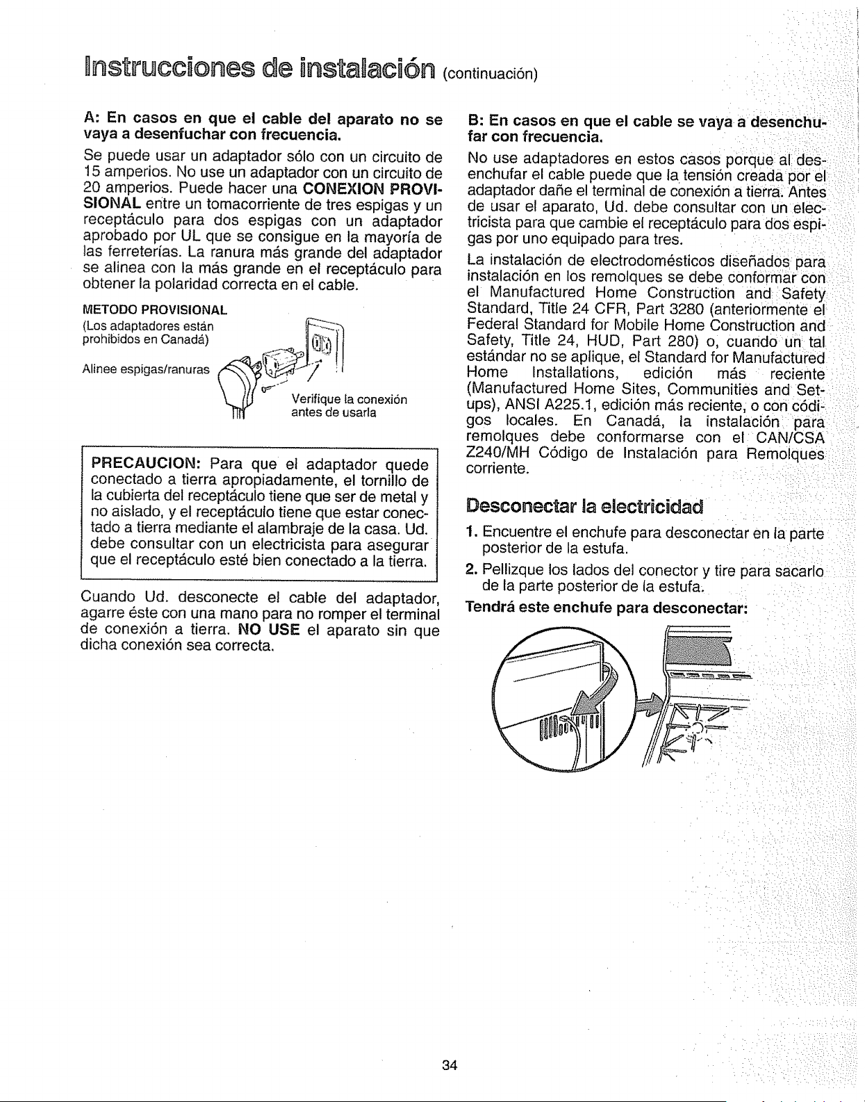
lnstrucciones de instalaci6n (oont noao 0n)
A: En casos en que el cable del aparato no se
vaya a desenfuchar con frecuencia.
Se puede usar un adaptador sOlo con un circuito de
!5 amperios. No use un adaptador con un circuito de
20 amperios. Puede hacer una CONEXION PROVI-
SIONAL entre un tomacorriente de tres espigas y un
receptaculo para dos espigas con un adaptador
aprobado por UL que se consigue en la mayorfa de
las ferretefias. La ranura m_s grande del adaptador
se alinea con lamas grande en et recept_tculo para
obtener la polaridad correcta en el cable.
METODO PROVISIONAL
(Los adaptadores esta.n --_._.
prohibidos en Canada) ''_"_
Alinee espigas/ranuras (_'_'{;_J'i !I
\,..._ I._'' Verifique ia conexi6n
r[_ antes de usarla
PRECAUClON: Para que el adaptador quede
conectado a tierra apropiadamente, el tornillo de
la cubierta del recept_.culo tiene que ser de metal y
no aislado, y el recept_,cuto tiene que estar conec-
tado a tierra mediante el alambraje de la casa. Ud.
debe consultar con un electricista para asegurar
que el recept&culo este bien conectado a la tierra.
Cuando Ud. desconecte el cable del adaptador,
agarre este con una mano para no romper el terminal
de conexiOn a tierra. NO USE el aparato sin que
dicha conexiOn sea correct&
B: En casos en que el cable se vaya a desenchu-
far con frecuencia.
No use adaptadores en estos casos porque al des,
enchufar el cable puede que la tension creada por el
adaptador daSe el terminal de conexiOn a tierral Antes
de usar el aparato, Ud. debe consultar con un elec-
tricista para que cambie et receptdtculo para dos' espi-
gas por uno equipado para tres.
La instalaci0n de electrodomesticos diseSados para
instalaciOn en los remolques se debe conformar con
el Manufactured Home Construction and Safety
Standard, Title 24 CFR, Part 3280 (anteriormente el
Federal Standard for Mobile Home Construction and
Safety, Title 24, HUD, Part 280) o, cuando'un tal
est_,ndar no se aplique, el Standard for Manufactured
Home installations, edici0n m_.s reciente
(Manufactured Home Sites, Communities and Set-
ups), ANSI A225.1, ediciOn m_.s reciente, o con cOdi-
gos locales. En Canada, ia instalaci0n para
remolques debe conformarse con el CAN/CSA
Z240/MH COdigo de InstalaciOn para Remolques
corriente.
Desconectar la electricidad
1. Encuentre el enchufe para desconectar en la parte
posterior de la estufa.
2. Pellizque los lados del conector y tire para sacarlo
de la parte posterior de la estufa;
Tendr& este enchufe para desconectar:
34
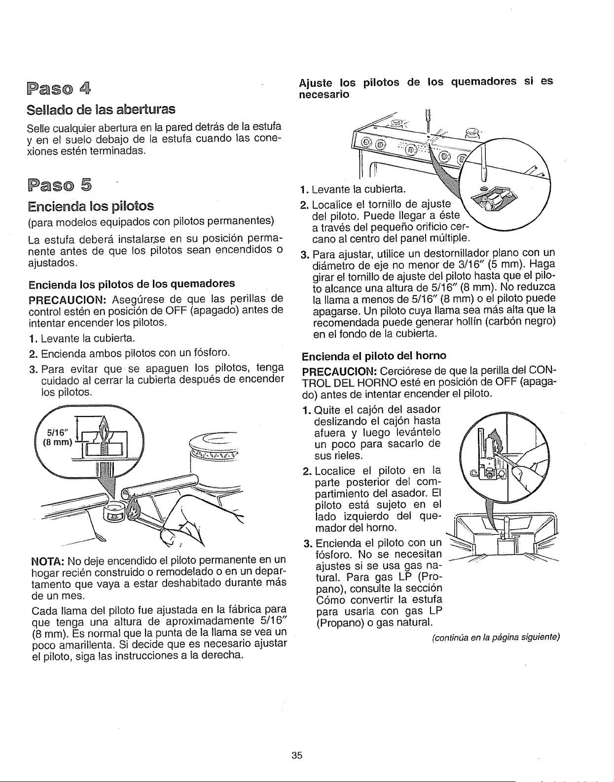
4
SeD ado de las aber uras
Selle cualquier abertura en la pared detr_s de la estufa
yen el suefo debajo de la estufa cuando las cone-
xiones est6n terminadaso
Ajuste los pilotos de los quemadores si es
necesario
5
Encienda gos pi!otos
(para modelos equipados con pilotos permanentes)
La estufa debera instalar.se en su posici6n perma-
nente antes de que los pilotos sean encendidos o
ajustados.
Encienda los pilotos de los quemadores
PRECAUCION: Aseg_rese de que las perillas de
control esten en posici6n de OFF (apagado) antes de
intentar encender los pilotos.
1. Levante la cubierta.
2. Encienda ambos pi!otos con un f6sforo.
3. Para evitar que se apaguen los pilotos, tenga
cuidado a! cerrar la cubierta despues de encender
los pitotos.
NOT#,: No deje encendido el piloto permanente en un
hogar recien construido o remodelado o en un depar-
tamento que vaya a estar deshabitado durante mAs
de un rues.
Cada llama del piloto rue ajustada en la f_Sbrica para
que tenga una altura de aproximadamente 5/16"
(8 mm). Es normal que la punta de la llama se yea un
poco amarillenta. Si decide que es necesario ajustar
el piloto, siga las instrucciones a ta derecha.
lx
2.
3_
Levante la cubierta.
Localice el tornil]o de ajuste
del piloto. Puede Ilegar a _ste
a trav_s del pequeSo orificio cer-
cano at centro del panel mt)ltiple.
Para ajustar, utilice un destornillador piano con un
di_.metro de eje no menor de 3/16" (5 ram). Haga
girar el tornillo de ajuste del piloto hasta que el pilo-
to alcance una altura de 5/16" (8 mm). No reduzca
la llama a menos de 5/16" (8 ram) o el pitoto puede
apagarse. Un pitoto cuya llama sea m_.s alta que la
recomendada puede generar hollin (carb6n negro)
en el rondo de la cubierta.
Encienda el piloto del homo
PRECAUClON: Cerci6rese de que la perilJa del CON-
TROL DEL HORNO este en posici6n de OFF (apaga-
do) antes de intentar encender el piloto.
1. Quite et cajbn del asador
deslizando el caj6n hasta _,_
afuera y luego levAntelo
un poco para sacaflo de i,
sus fieles.
2. Localice el piloto en la
parte posterior del com-
partimiento del asador. El
pi!oto est_ sujeto en el
lado izquierdo del que-
mador del homo.
3. Encienda el piloto con un
fdsforo. No se necesitan
ajustes si se usa gas na-
tural. Para gas LP (Pro-
pano), consulte la secci6n
C6mo convertir la estufa
para usarla con gas LP
(Propano) o gas natural.
(continEta en /a p#gina siguiente)
35
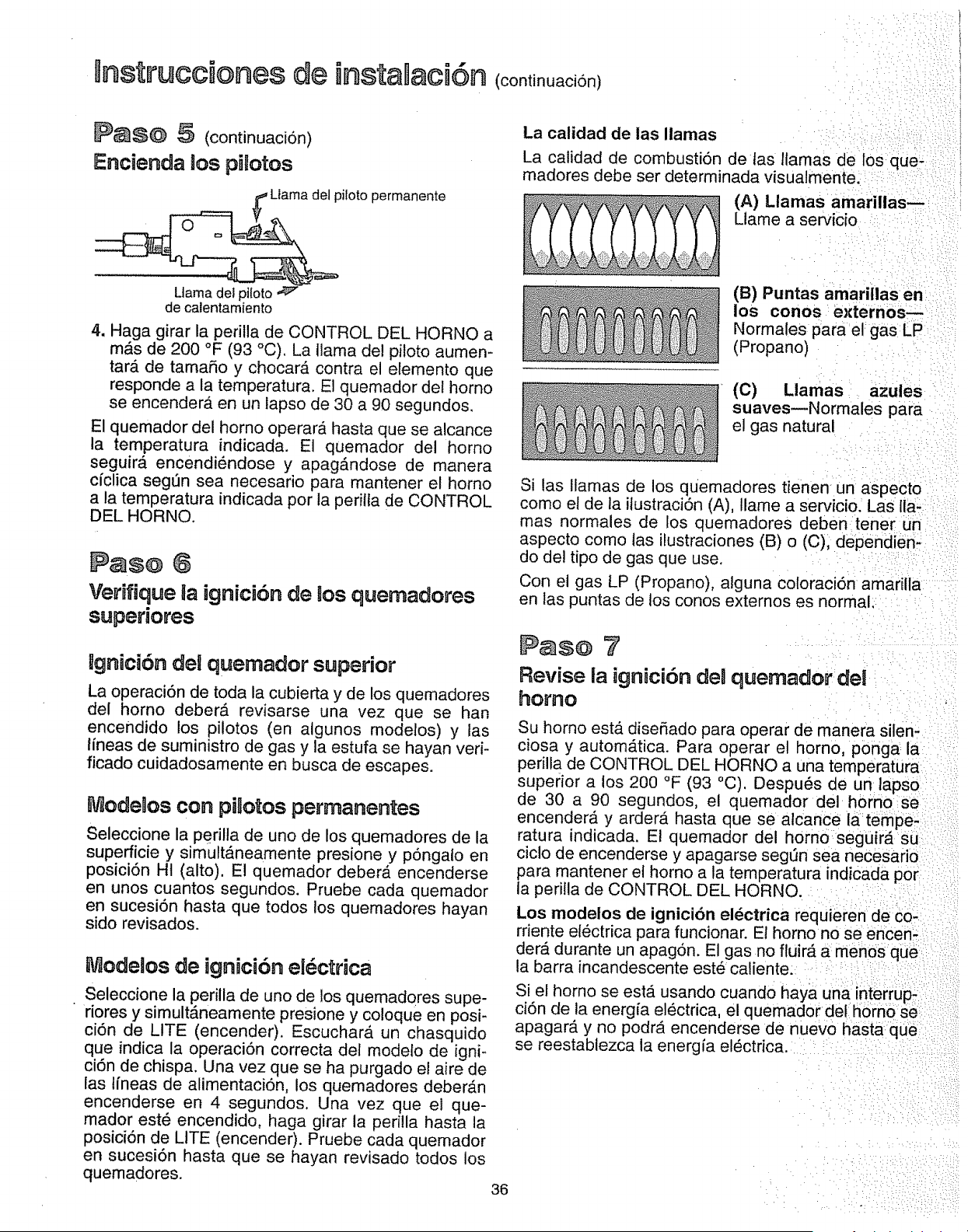
nstruccion÷s de DnstalaciSn/cont nuao o
_¢_) _ (continuaci6n)
Encienda tos pi_otos
del piloto permanente
Llama dei piloto
de calentamiento
4. Haga girar la perilla de CONTROL DEL HORNO a
m_.s de 200 °F (93 °C). La llama del piloto aumen-
tar_. de tamaSo y chocar_, contra el elemento que
responde a la temperatura. El quemador det homo
se encender_, en un lapso de 30 a 90 segundo&
El quemador del homo operara hasta que se alcance
la temperatura indicada. El quemador del homo
seguir_, encendiendose y apag&ndose de manera
cfclica seg_n sea necesario para mantener el homo
a la temperatura indicada por la perilta de CONTROL
DEL HORNO.
P so
Verifique ia ignicibn de los quernadores
superiores
_gnicibn dogquernador superior
La operaci6n de toda la cubierta y de los quemadores
de! homo deber& revisarse una vez que se han
encendido los pilotos (on algunos modelos) y las
Ifneas de suministro de gas y la estufa se hayan veri-
ficado cuidadosamente en busca de escapes.
_ode_os con pinetos permanentes
Seleccione la Perilla de uno de los quemadores de la
superficie y simult_neamente presione y p6ngalo en
posici6n Ht (alto). El quemador deber_t encenderse
en unos cuantos segundos. Pruebe cada quemador
en sucesi6n hasta que todos los quemadores hayan
sido revisados.
Medeles de ignicibn eldctrica
Seleccione la perilla de uno de los quemadores supe-
riores y simult&neamente presione y co!oque en posF
ci6n de LITE (encender). Escuchar& un chasquido
que indica la operaci6n correcta del modelo de igni-
ci6n de chispa, Una vez que se ha purgado el aire de
las tfneas de alimentaci6n, los quemadores deber&n
encenderse en 4 segundos, Una vez que el que-
mador est6 encendido, haga girar la perilla hasta la
posici6n de LITE (encender). Pruebe cada quemador
en sucesi6n hasta que se hayan revisado todos los
quemadores.
La calidad de las llamas
La calidad de combusti6n delas llamas de los que-
madores debe ser determinada visualmente.
(A) Llamas amarillas--
Llame a servicio
(B) Puntas amarillas en
los COHOS e×ternos--
Normales para el gas LP
(Propano)
(C) Llamas azules
suaves--Normales para
el gas natural
Si tas llamas de los quemadores tienen un aspecto
como et de la itustraci6n (A), Ilame a servicio. Las lla;-
mas normales de los quemadores deben tenor un
aspecto como las ilustraciones (B) o (C), dependien-
do del tipo de gas que use.
Con el gas LP (Propano), alguna coloraci6n amarilla
en las puntas de los COHOSexternos es normal:
P s@ 7
Revise la ignici6n del quernador de_
homo
Su homo est,. diser_ado para operar de manera silen-
ciosa y automAtica. Para operar el homo, ponga la
perill a de CONTROL DEL HORNO a una temperatura
superior a los 200 °F (93 °C). Despu_s de un lapso
de 30 a 90 segundos el quemador del horno se
encender_, y arder,_ hasta que se atcance latempe-
ratura indicada. El quernador del horno seguirA su
ciclo de encenderse y apagarse segLin sea necesario
para mantener el homo a la temperatura indicada por
la perifla de CONTROL DEL HORNO.
Los modelos de ignici6n el_ctrica requieren de co-
36
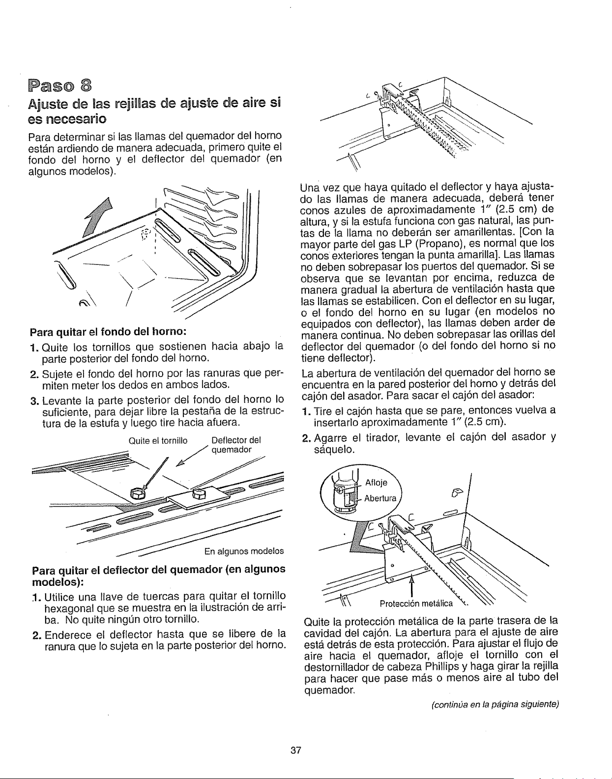
ag@ 8
Ajuste de las reiiUUasde ajuste de aire si
es necesario
Para determinar si las llamas del quemador del horno
est&n ardiendo de manera adecuada, pdmero quite el
rondo del homo y el deflector del quemador (en
algunos modelos).
Para quitar el fondo del horno:
1. Quite los tornil!os que sostienen hacia abajo la
parte posterior del fondo del homo.
2. Sujete el fondo dei homo por las ranuras que per-
miten meter los dedos en ambos lados.
3. Levante la parte posterior del rondo del homo Io
suficiente, para dejar libre la pestafa de la estruc-
tura de ta estufa y luego tire hacia afuera.
Quite el tornil]o Deflector def
_j_ quemador
Una vez que haya quitado el deflector y haya ajusta-
do las llamas de manera adecuada, deber_, tener
COHOSazutes de aproximadamente 1" (2.5 cm) de
altura, y si la estufa funciona con gas naturat, las pun-
tas de la llama no deberan ser amarillentas. [Con la
mayor parte del gas LP (Propano), es normal que los
COHOSexteriores tengan la punta amarilla]. Las llamas
no deben sobrepasar los puertos del quemador. Si se
observa que se levantan por encima, reduzca de
manera gradual la abertura de ventiiaci6n hasta que
las llamas se estabilicen. Con et deflector en su lugar,
o el fondo del homo en su lugar (en modelos no
equipados con deflector), 1as llamas deben arder de
manera continua. No deben sobrepasar las orillas del
deflector del quemado r (o del rondo del homo si no
tiene deflector).
La abertura de ventifaci6n del quemador del homo se
encuentra en la pared posterior det homo y detr_.s del
caj6n del asador. Para sacar et caj6n del asador:
1. Tire el caj6n hasta que se pare, entonces vuelva a
insertarlo aproximadamente I" (2.5 cm).
2. Agarre el tirador, levante el caj6n del asador y
s&quelo.
Para quitar el deflector del quemador (en algunos
modelos):
.1. Utilice una IIave de tuercas para quitar el tornillo
hexagonal que se muestra en la ilustraci6n de arri-
ba. No quite ningL_n otro tornillo.
2. Enderece el deflector hasta que se tibere de Ia
ranura que 1osujeta en la parle posterior del homo.
Protecci6n met&lica
Quite la protecci6n metalica de la parte trasera de la
cavidad del caj6n. La abertura para el ajuste de aire
est_ detr_,s de esta protecci6n. Para ajustar el flujo de
aire hacia et quemador, afloje el tornil!o con el
destornitlador de cabeza Phillips y haga girar la rejilla
para hacer que pase m_s o menos aire al tubo del
quemador.
(continOa en la p_gina siguiente)
37
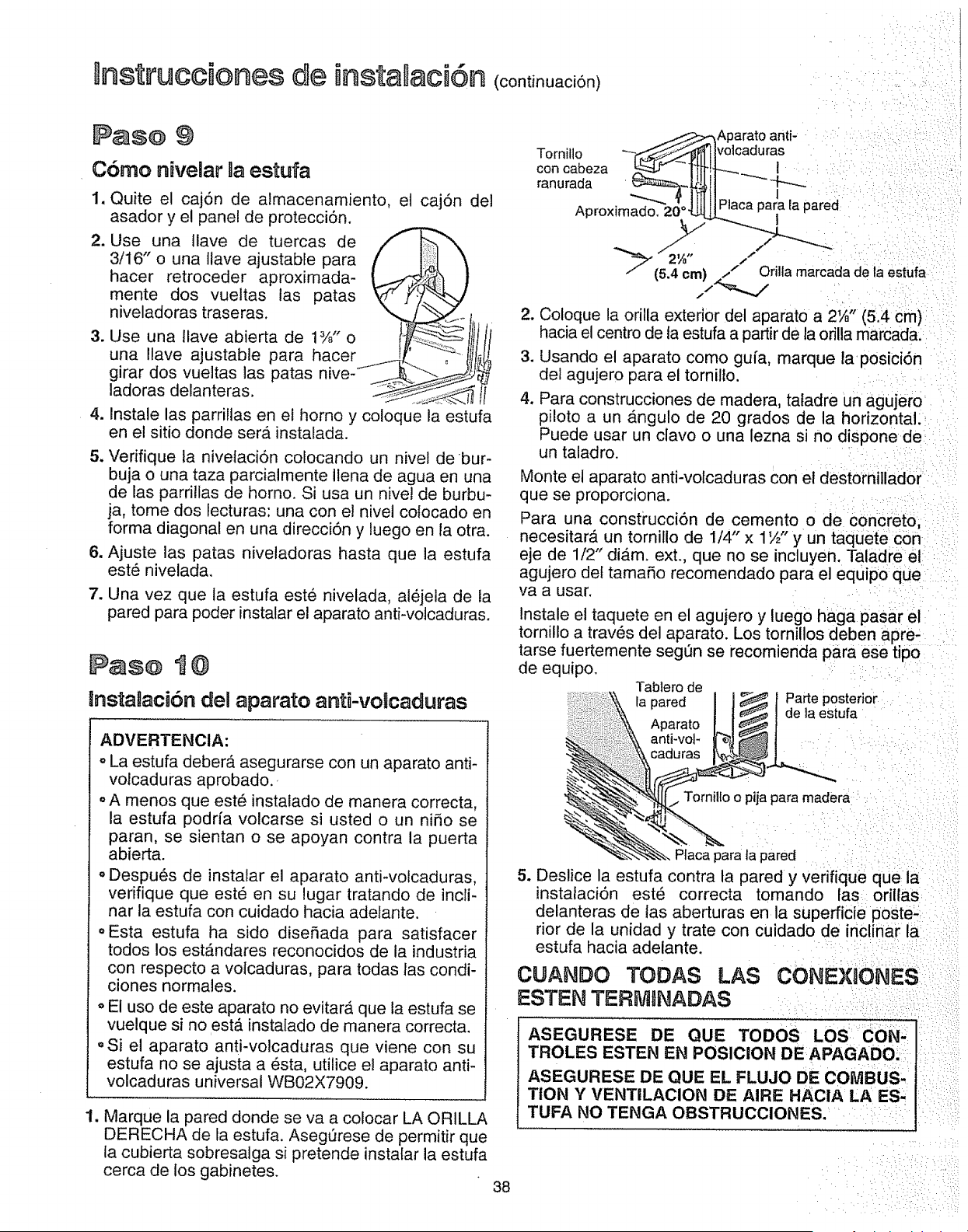
nnstruccion÷s de insta0aci6n (cont nuac 6n)
9
C6rno niveiar estufa
1, Quite e! caj6n de almacenamiento, et cajSn del
asador y e! panel de protecciSn.
2. Use una llave de tuercas de ,_ _'_
3/16" o una liave ajustable para /'
hacer retroceder aproximada- L.....TC _
mente dos vueltas las paras _ j'
Useniveladorasllavetraseras. , _ l_ _ iIitli
3.
una abierta de 1¾' o r_'
una Ilave ajustable para hacer __..jf_''
dos nive-
ladoras delanteras.
4. Instale las parrillas en el homo y coloque la estufa
en el sitio donde sera instalada.
5. Verifique la nivelaciSn colocando un nivel de bur-
buja o una taza parcialmente Ilena de agua en una
de las parrillas de horno. Si usa un nivel de burbu-
ja, tome dos lecturas: una con el nivel colocado en
forma diagonal en una direcdSn y luego en la otra.
6. Ajuste las patas niveladoras hasta que la estufa
est_ nivelada.
7. Una vez que la estufa este nivelada, al_jela de la
pared para poder instalar el aparato anti-votcaduras.
InstaJaci6n del aparato anti-voicaduras
:ii% i
__Aparato anti- ::
Tornillo "-"_J'_l {votcaduras : ':
con cabeza _ - 11tJr!_-. I .... : :
ranurada ' _-U}JII
Aproximad-_-o. 20_o_Placa para la pared
/(5,4 cm) ./ Orilla marcada de la
2. Coloque la orilla exterior del aparato a 21/_" (5.4:cm):
hacia el centro de ta estufa a partir de la orilla marcada? I
3. Usando el aparato como gufa, marque laposiciSn :i:i:
del agujero para el tornilto.. _:
4. Para construcciones de madera, taladre un agujero ,
piloto a un angulo de 20 grados de la horizontal: ::
Puede usar un clavo o una lezna si no dispone de _i_
un taladro. .... :
Monte el aparato anti-volcaduras con el destornillador i
que se proporciona ...........
Para una construcciSn de cemento o de concret0, i
necesitar_ un torniHo de 1/4"x 1½" y un taquete €0n
eje de 1/2" di&m. ext., que no se incluyen. Taladre el
agujero def tamaSo recomendado para el equipo que
va a usar.
Instale el taquete en el agujero y luego haga pasar el
tornillo a tray,s del aparato. Los tornillos deben apre-
tarse fuertemente segt_n se recomienda para ese tipo
de equipo.
Tabiero de
Parte posterior
de la estufa
ADVERTENCIA:
oLa estufa debera asegurarse con un aparato anti-
volcaduras aprobado..
° A menos que est_ instalado de manera correcta,
la estufa podrfa volcarse si usted o un niSo se
paran, se sientan o se apoyan contra la puerta
abierta.
o Despu_s de instalar el aparato anti-volcaduras,
verifique que est_ en su lugar tratando de incli-
nar la estufa con cuidado hacia adetante.
oEsta estufa ha sido diseSada para satisfacer
todos los estAndares reconocidos de la industria
con respecto a volcaduras, para todas las condi-
clones normales.
o El uso de este aparato no evitara que la estufa se
vuelque si no est,. instalado de manera correct&
o Si el aparato anti-volcaduras que viene con su
estufa no se ajusta a _sta, utilice el aparato anti-
volcaduras universal WB02X7909.
1. Marque la pared donde se va a colocar LA ORILLA
DERECHA de la estufa. AsegQrese de permitir que
la cubierta sobresaiga si pretende instaIar la estufa
cerca de los gabinetes.
Tornil[o o piia para madera
i"
Placa para ta pared
5. Deslice la estufa contra ta pared y verifique que la
instalaci6n est_ correcta tomando las orillas
delanteras de las aberturas en la superficie poste-:
rior de la unidad y trate con cuidado de inclinar la
estufa hacia adelante.
CUANDO TODAS LAS CONEXIIONES
ESTEN TERM]NADAS
ASEGURESEE DE QUE TODOS LOS CON-;
TROLES ESTEN EN POSICION DE APAGADO.
ASEGURESE DE QUE EL FLUJO DE COMBUS.
TtON Y VENTILACION DE AIRE HACIA LA ES.
TUFA NO TENGA OBSTRUCCIONES.
38
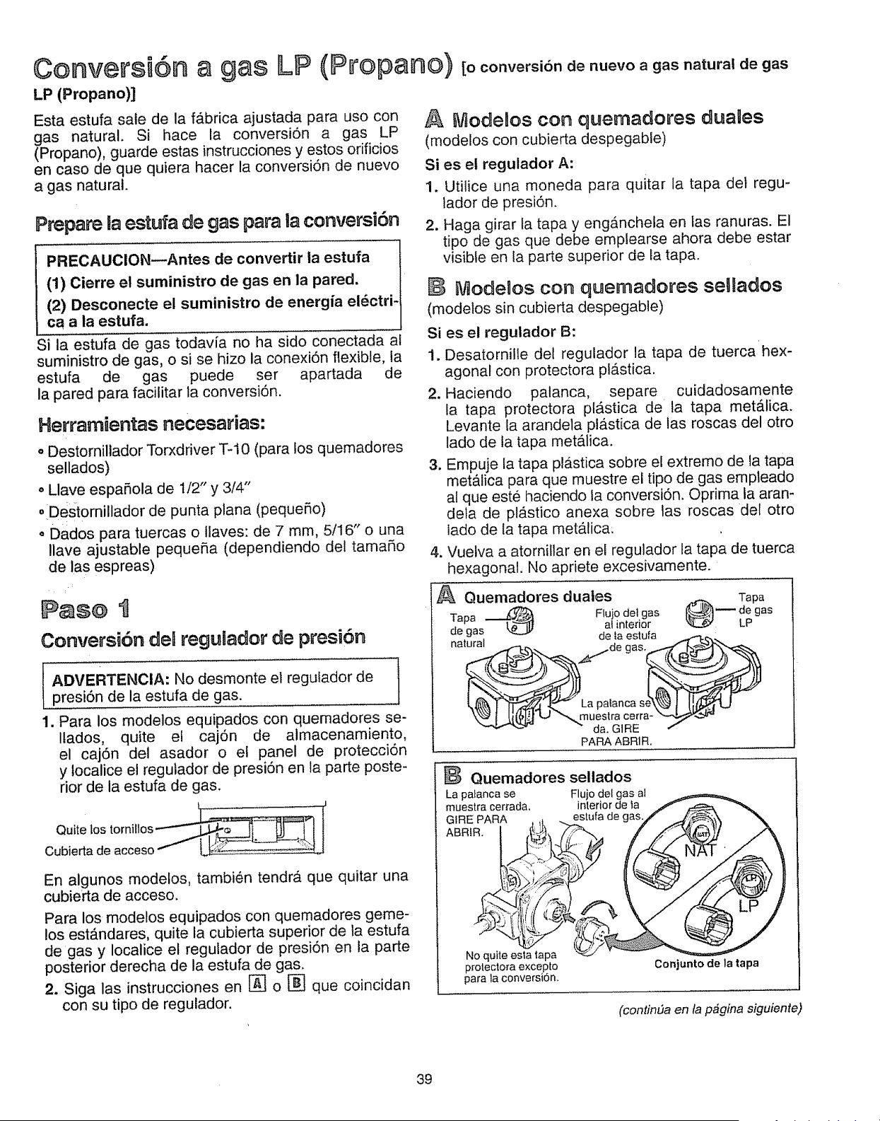
Cenversi6n
LP (Propano)]
a gas LP (Ptopano) [o a gas natural degas
Esta estufa sale de la f,_brica ajustada para uso con
gas natural. Si hace la conversi6n a gas LP
(Propano), guarde estas instrucciones y estos orificios
en caso de que quiera hacer la conversi6n de nuevo
a gas natural.
Prepare ta estufa de gas para la conversi6n
PRECAUCION--Antes de convertir la estufa
(1) Cierre el suministro de gas en la pared.
(2) Desconecte el suministro de energia eldctri-
ca a la estufa.
Si la estufa de gas todavia no ha sido conectada al
suministro de gas, o si se hizo la conexi6n flexible, la
estufa de gas puede ser apartada de
la pared para facilitar la conversi6n.
Herramientas necesarias:
o Destornillador Torxdriver T-10 (para los quemadores
sellados)
o Llave espaSola de 1/2" y 3/4"
o Destornillador de punta plana (pequeSo)
o Dados para tuercas o ilaves: de 7 mm, 5/16" o una
Ilave ajustable pequeSa (dependiendo del tamaSo
de las espreas)
Conversi6n dei regulador de presi6n
i ADVERTENCIA: No desmonte el regulador de
presiSn de la estufa de gas.
1. Para los modelos equipados con quemadores se-
Itados, quite el cajSn de almacenamiento,
el caj6n del asador o el panel de protecciSn
y localice el regulador de presi6n en la parte poste-
rior de la estufa de gas.
Quite los tornillos_ 1'
Cubierta de acceso ""- t__,_U
En algunos modelos, tambi6n tendrA que quitar una
cubierta de acceso.
Para los modelos equipados con quemadores geme-
!os est_ndares, quite la cubierta superior de la estufa
de gas y Iocalice el regulador de presi6n en la parte
posterior derecha de la estufa de gas.
2. Siga las instrucciones en r_ o [_ que coincidan
con su tipo de regulador.
ModeBos con quernadores duaUes
(modelos con cubierta despegable)
Si es el regulador A:
1. Utilice una moneda para quitar la tapa det regu-
lador de presi6n.
2. Haga girar la tapa y enganchela en las ranuras. El
tipo de gas que debe emplearse ahora debe estar
visible en la parte superior de la tapa.
#odeBos con quemadores seltados
(modelos sin cubierta despegable)
Si es el regulador B:
1. Desatornille del regulador la tapa de tuerca hex-
agonal con protectora pl_,stica,
2. Haciendo palanca, separe cuidadosamente
fa tapa protectora pl#,stica de la tapa met_.lica.
Levante la arandela plastica de las roscas del otro
lado de la tapa met,_lica.
3. Empuje la tapa plastica sobre el extremo de la tapa
metb, lica para que muestre el tipo de gas empleado
al que este haciendo la conversi6n. Oprima la aran-
deia de pl&stico anexa sobre las roscas del otro
iado de la tapa met_tlica.
4. Vuelva a atornillar en el regulador la tapa de tuerca
hexagonal. No apriete excesivamente.
Quemadores duales ._,.=, Tapa
Tapa _ Flujo del gas _) _ de gas
at intedor "_..,4_ LP
de gas_ de fa estufa
natural _ de as _'_
"_l_.L_ _ "_mue_t_a°e_r_-"---_'-_
da. GIRE /
PARA ABR1R.
Quemadores sellados
La palanca se Flujo del gas al
muestra cerrada, interior de la
GIRE PARA estufa de gas,
ABRfR,
No quite esla tapa
protectora excepto
para la conversi6n,
Conjunto de la tapa
(continOa en ta pbgina siguiente)
39
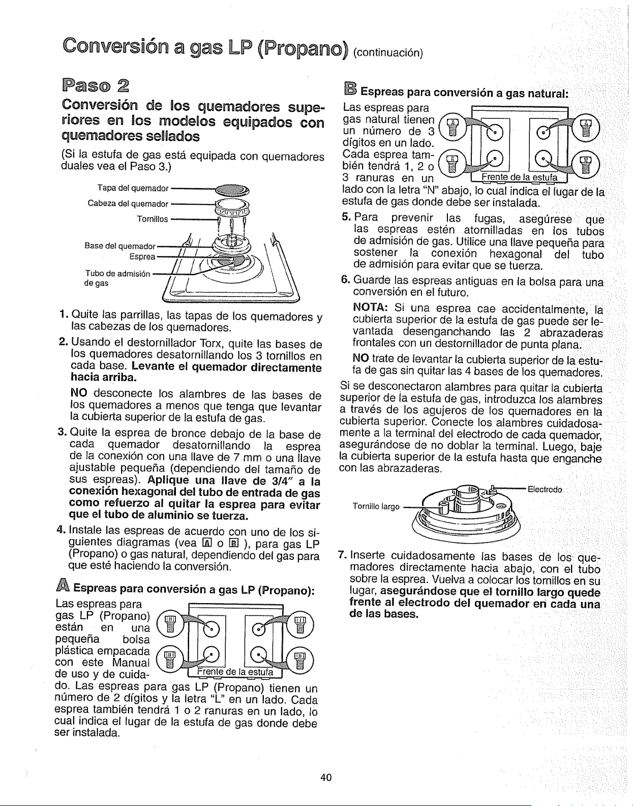
CenversiSn a gas LP (Pmpano)/coo,nuncio°)
P s@ 2
Conversibn de los quemadores supe-
riores en los modeUos equipados con
quemadores sen ados
(Si la estufa de gas est,. equipada con quemadores
duales vea el Paso 3.)
Tapa deI quemador
Cabeza del quemador
Torniltos i
Base del quemador
Esprea
Tubo de adm{siSn
1. Quite las parrillas, las tapas de los quemadores y
las cabezas de los quemadores.
2. Usando el destornillador Torx, quite las bases de
los quemadores desatomi!lando los 3 tornillos en
cada base. Levante el quemador directamente
hacia arriba.
NO desconecte los alambres de las bases de
los quemadores a menos que tenga que levantar
la cubierta superior de la estufa de gas.
3, Quite la esprea de bronce debajo de la base de
cada quemador desatornillando la esprea
de fa conexiSn con una llave de 7 mm o una llave
ajustable pequeSa (dependiendo del tamaSo de
sus espreas). Aplique una Ilave de 3/4" a la
conexibn hexagonal del tubo de entrada de gas
como refuerzo al quitar ia esprea para evitar
que el tubo de aluminio se tuerza.
4, Instale las espreas de acuerdo con uno de los si-
guientes diagramas (yea [] o [] ), para gas LP
(Propano) o gas natural, dependiendo del gas para
que est_ haciendo la conversi6n.
Espreas para conversibn a gas LP (Propano):
Las espreas para
gas LP (Propano)
est&n en una
pequeSa bolsa
plastica empacada(_
con este Manual
de uso y de cuida-
r_enle de laesl_ufa
do. Las espreas para gas LP (Propano) tienen un
n,3mero de 2 d(gitos y la letra "L" en un lado. Cada
esprea tambi_n tendra 1 o 2 ranuras en un lado, 1o
cual indica el lugar de la estufa de gas donde debe
ser instalada.
Espreas para conversi6n a gas naturah ::
Las espreas para
gas natural tienen
un nt_mero de 3
d(gitos en un iado.
Cada esprea tam-
bi_n tendr& 1, 2 o
3 ranuras en un
Frente de la estufa
lado con la letra "N" abajo, Io cual indica el lugar de la
estufa de gas donde debe set instalada.
5. Para prevenir las fugas, asegL_rese que
las espreas est_n atomilladas en los tubos
de admisi6n de gas. Utilice una Ilave peque_a para
sostener Fa conexiSn hexagonal del tub0
de admisiSn para evitar que se tuerza.
6. Guarde las espreas antiguas en la bolsa para una
conversiSn en el futuro.
NOTA: Si una esprea cae accidentalmente; la
cubierta superior de la estufa de gas puede ser le-
vantada desenganchando las 2 abrazaderas
frontales con un destomillador de punta plana.
NO trate de levantar la cubierta superior de la estu-
fa de gas sin quitar las 4 bases de los quemadores.
Si se desconectaron alarnbres para quitar la cubierta
superior de ia estufa de gas, introduzca los alambres
a trav_s de los agujeros de los quemadores en la
cubierta superior. Conecte los alambres cuidadosa-
mente a la terminal del electrodo de carla quemador,
asegur_ndose de no doblar la terminal. Luego, baje
la cubierta superior de la estufa hasta que enganche
con las abrazaderas.
Tomillo largo --
7. Inserte cuidadosamente las bases de los que;
madores directamente hacia abajo, conel tubo
sobre la esprea. Vuelva a colocar los tornillos en su
lugar, asegurdndose que el tornillo largo quede
frente al electrodo dei quemador en cada una
de las bases.
40
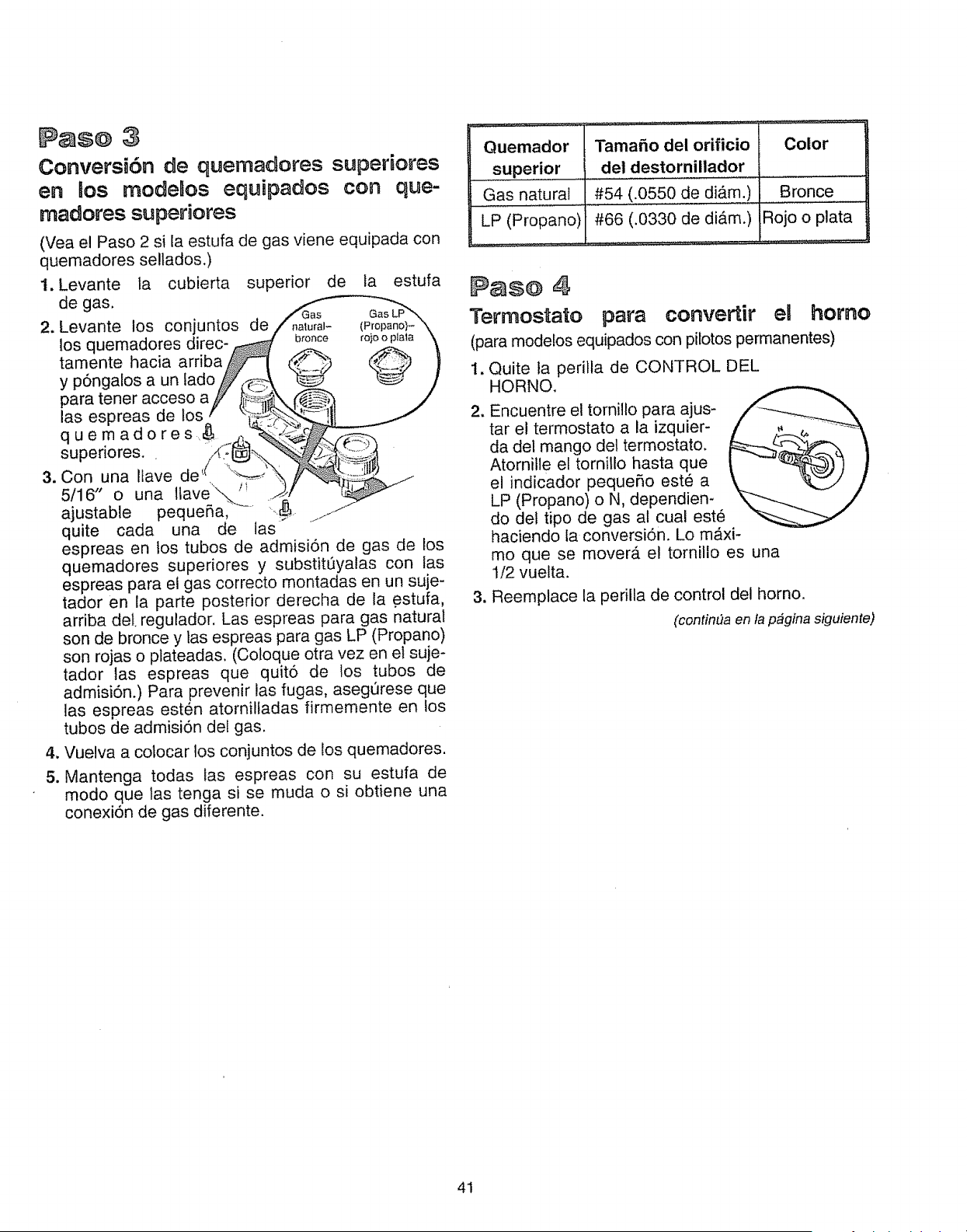
Conversibn de quernadores superiores
en Ros rnodemos equipados con que-
madores supedores
(Yea el Paso 2 si la estufa de gas viene equipada con
quemadores sellados.)
1.Levante la cubierta superior de la estufa
degas. __X
2, Levante los conjuntos de
los quemadores direc_e _°_ _ \
tamente hacia arrib___._)
y p6ngalos a un lado __ _ /
para tener acceso a F ]'__. ../
las espreas de los_'_!il
quemadores & _'__
superiores. _J;_
3. Con una ilave de'(_ll_ 1-
5/16" o una ltave"_,/' _-__
ajustable peque_a_- :_,_ j---Y_
quite cada una de las ....
espreas en los tubos de admisi6n de gas de los
quemadores superiores y substitOyalas con las
espreas para el gas correcto montadas en un suje-
tador en la parte posterior derecha de la ,estufa,
arriba de[ regulador. Las espreas para gas natural
son de bronce y las espreas para gas LP (Propano)
son rojas o plateadas. (Coloque otra vez en el suje-
tador las espreas que quit6 de los tubos de
admisi6n.) Para prevenir las fugas, asegOrese que
las espreas est6n atornilfadas firmemente en los
tubos de admisi6n del gas,
4, Vuelva a colocar los conjuntos de los quemadores.
5. Mantenga todas las espreas con su estufa de
modo que las tenga si se muda o si obtiene una
conexi6n de gas diferente,
Quemador Tama5o del orificio Color
.......superior , del,d,e,stornillador ...........
Gas natural #54 (.0550 de dis.m.) Bronce
LP (Propano) #66 (,0330 de di&m,) Rojo o plata
Paso 4
Terrnostato para convertir el homo
(para modelos equipados con pilotos permanentes)
1, Quite la perilla de CONTROL DEL
HORNO,
2_
Encuentre el tomillo para ajus-
tar el termostato a la izquier-
da del mango del termostato.
Atornille el tornillo hasta que
el indicador pequefio est_ a
LP (Propano) o N, dependien-
do def tipo de gas al cual est_
haciendo la conversi6n. Lo m&xi-
mo que se movera el tornillo es una
1/2 vuelta.
3. Reemplace la perilla de control del horno.
(contindta en la pbgtna siguiente)
41
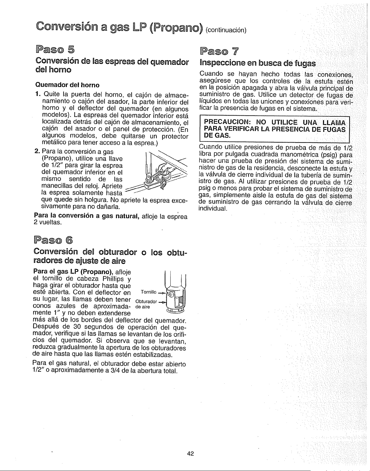
ConversiSn a gas LP (Prepano) coo, oo c o
P so 5
Cenversibn de las espreas de1 quemador
dea homo
Quemador de! horno
1. Quite la puerta del horno, el cajSn de almace-
namiento o caj6n del asador, ta parte inferior del
horno y el deflector del quemador (en algunos
modelos). La espreas del quemador inferior est,.
Iocalizada detras del caj6n de almacenamiento, el
caj6n del asador o el panel de protecci6n. (En
algunos modelos, debe quitarse un protector
met_lico para tener acceso a la esprea.)
2. Para la conversiSn a gas _l_._
(Propano), utitice una ilave
de 1/2" para girar la esprea
del quemador inferior en el
mismo sentido de las
manecillas del reloj. Apriete
la esprea solamente hasta
que quede sin holgura. No apriete la esprea exce-
sivamente para no daSarla.
Para la conversibn a gas natural, afloje la esp'rea
2 vueltas.
••:•, i••••i.••_••••/_••••_••_•:•••••••••_i••__••i_i•i
Inspecciene en busca de fugas
=_r
:
=
:_
::_
Cuando se hayan hecho todas las.:conexioiies_ ::
asegerese que los controles de la estufa:est_n _
en la posiciSn apagada y abra la v_.tvula principal de:
suministro de gas. Utilice un detecto r, de fugas de :ii:
i(quidos en todas las uniones y conexlones para ven_
ficar la presencia de fugas en el sistema.
; : ..... i :
PRECAUCION: NO UTILICE UNA: LLAMA I:
PARA VERIFICAR LA PRESENCIA DE FUGAS[ i
DE GAS.
I
Cuando utilice presiones de prueba de m&sde 1/2_:
libra por pulgada cuadrada manom6trica (psig)para
hacer una prueba de presiSn del sistema de sumi, _
nistro de gas de la residencia, desconecte la estufa y i_i_:
la valvula de cierre individual de la tuberia de sumin-
istro de gas. AI utilizar presiones de prueba de:l/2
psig o menos para probar el sistema de suministro de
gas simplemente aisle la estufa de gas de/sistema
de suministro de gas cerrando la v_.lvUta de cierre
individual.
Pas® @
Conversibn den obturador o los obtu-
radores de ajuste de aire
el tornillo de cabeza Phillips y
haga girar el obturador hasta que ....
este abierta. Con el deflector en Tornit!o
SU lugar, las llamas deben tener Obturador
COHOS azules de aproximada-deaire -_
mente 1" y no deben extenderse
m_.s all_ de los bordes del deflector del quemador.
Despu_s de 30 segundos de operaciSn del que-
mador, verifique si las llamas se levantan de los orifi-
cios del quemador. Si observa que se levantan,
reduzca gradualmente la apertura de los obturadores
de aire hasta que las llamas est_n estabilizadas.
Para el gas natural, el obturador debe estar abierto
1/2" o aproximadamente a 3/4 de ta abertura total.
42
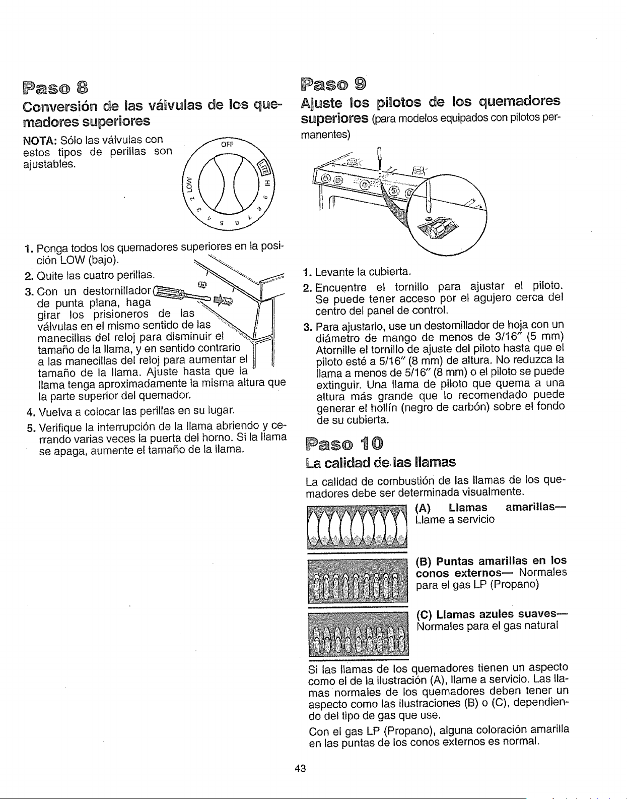
as® $
Conversibn de las v_Bvunas de los que-
madores superiores
NOTA: $6!o las vb.lvulas con
estos tipos de perillas son
ajustables.
!
1. Ponga todos los quemadores supedores en ta posi-
ci6n LOW (bajo).
21 Quite tas cuatro perillas.
3. Con un destornillador_ @
de punta plana, haga_ @.,_
girar los prisioneros de las
v41vulas en el mismo sentido de las
manecillas del reloj para disminuir el
tamaRo de la llama, y en sentido contrario
a las manecillas del retoj para aumentar et
tamaRo de la llama. Ajuste hasta que la
llama tenga aproximadamente la misma altura que
la parle superior del quemador.
4. Vuetva a colocar las perillas en su lugar.
5. Verifique la interrupci6n de la llama abriendo y ce-
rrando varias veces la puerta del horno. Si la llama
se apaga, aumente el tamaSo de ta llama.
Ajuste los pilotos de los quernadores
superiores (para modelos equipados con pilotos per-
manentes)
2.
3_
Levante la cubierta.
Encuentre el tornillo para ajustar el piloto.
Se puede tener acceso por el agujero cerca del
centro del panel de control.
Para ajustarlo, use un destornillador de hoja con un
diAmetro de mango de menos de 3/16" (5 ram)
Atornille el tornillo de ajuste del piloto hasta que el
piloto est_ a 5/16" (8 ram) de altura. No reduzca la
llama a menos de 5/16" (8 mm) o el piloto se puede
extinguir. Una llama de pitoto que quema a una
altura mAs grande que Io recomendado puede
generar el hotlfn (negro de carb6n) sobre el fondo
de su cubierta.
as¢ t @
La caRidad de. las llamas
La calidad de combusti6n de las llamas de los que-
madores debe ser determinada visualmente.
(A) Llamas amarillas_
Llame a servicio
(B) Puntas amarillas en los
conos externos_ Normales
para el gas LP (Propano)
(C) Llamas azules suaves_
Normales para el gas natural
Si las llamas de los quemadores tienen un aspecto
como el de la ilustraci6n (A), Ilame a servicio. Las lla-
mas normales de los quemadores deben tener un
aspecto como las ilustraciones (B) o (C), dependien-
do del tipo de gas que use.
Con el gas LP (Propano), alguna coloraci6n amarilla
en las puntas de los COHOSexternos es normal.
43
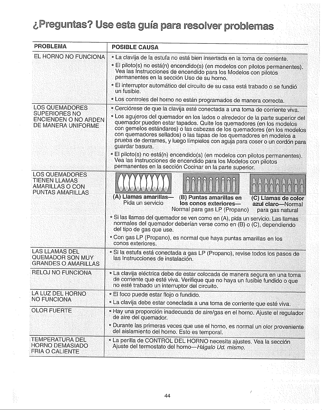
&Preguntas? Use ÷sta gu_a para reso_ver probaemas
PROBLEMA
:EL FIORNO:NO:'FUNCiOI
: .... :
!::_ i:: ¸ !:, :::.: : _:
:,i_:i,2,:L:i:il:,ii:i,i
:LOS QU EMADORES :::::::;:::::::::;::::::
SUPERIORES :O::::: ,:::::::::::::::::::::::::::::
ENCiENDEN::O NO::ARDEN
DE: MANERAUNll
LOS Q U EMADOR ES;::;:::::::::::::;!:
'TIEI'
::PUN'q
:TEMI:
: :
POSIBLE CAUSA
:::::::::::::::::::::::: : ::: ::
t]anera: corre(
i secci6n :Cocina_ en::la: parte superior;
a:eI_btrica:debede:::estarc610cada:.:d
c0rriente
44
• : I,:I,I::iI_:':iL:::_I_::'i_:,I
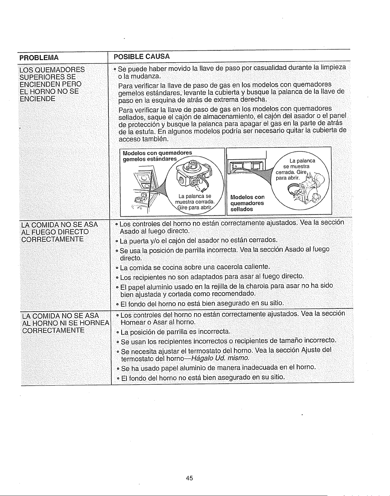
PROBLEMA
SU ERIQRES
_ CDM!DA NO: SE ASA:::::: ::
NI SEHORI'
POSIBLE CAUSA
eme
i: :Seliad6s, : :
: :::,.:::: =: .:::::::1:1:1:i:1= :
Modelos con quemadores
gemc
necesan0q
Modelos con
quemadores
sellados
:L0:S:c6ntrbles: no est&n::c0¢rectamente: a
:!noestA:bien aseg
usta.dos:!::Vea :::::::::::::::::::::::::
45

NOTA$
46

NOTA$
47
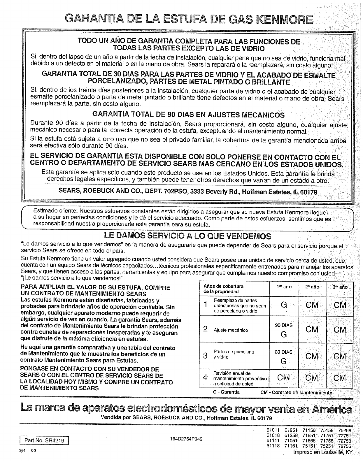
GARANT A DE LA ESTUFA DE GAS KENMORE
TODO UN AI_O DE GARANTIA CONIPLETA PARA LAS FUNCiONES DE
TODAS LAS PARTES EXCEPTO LAS DE VIDRIO
Si, dentro del lapso de un aSo a partir de la fecha de instalacidn, cualquier parte que no sea de vidrio, funcionamal
debido aun defecto en el material o en la mano de obra, Sears la reparar_, o la reemplazar& sin costo alguno.
GARANTtA TOTAL DE 30 DaAS PARA LAS PARTES DE VIDRIO Y EL ACABADO DE ESMALTE
PORCELANBZADO, PARTES DE METAL PINTADO O BRgLLANTE
Si, dentro de los treinta dias poster|ores a ta instalacidn, cualquier parte de vidrio o el acabado de cuatquier
esmalte porcelanizado o parte de metal pintado o brillante tiene defectos en el material o mano de obra, sears
reemplazar_ la parte, sin costo alguno.
GARANTiA TOTAL DE 90 DIAS EN AJUSTES tVtECANICOS
Durante 90 dfas a partir de la fecha de instalacidn, Sears proporcionar_., sin costo alguno, cualquier ajuste
mec&nico necesario para la correcta operacidn de la estufa, exceptuando el mantenimiento normal.
Si la estufa est_ sujeta a otro uso que no sea el privado familiar, la cobertura de fa garantia mencionada arriba
ser_. efectiva sdlo durante 90 dias.
EL SERViC|O DE GARANTIA ESTA D_SPONIBLE CON SOLO PONERSE EN CONTACTO CON EL
CENTRO O DEPARTAtVtENTO DE SERVICtO SEARS MAS CERCANO ENLOS ESTADOS UNiDOS,
Esta garant{a se apiica sdlo cuando este producto se use en los Estados Unidos. Esta garantia ie brinda :
derechos legales especificos, y tambi_n puede tener otros derechos que varian de un estado a otro.
SEARS, ROEBUCK AND CO., DEPT. 702PSO, 3333 Beverly Rd, Hoffman Estates, IL 60179 : ::
I Est'mado clJente" __uestros esfuerzos con st antes est,n dir, g,dos a asegurar que su ha eva E s tufa Kenmore lleguel :; i i : i i:: i
a su hogar en perfectas eondiciones y le d_ el servicio adecuado. Como parte de estos esfuerzos, sentimos que
responsabitidad nuestra proporcionade esta garantia para su estufa.
LE DANOS SIERWCIO A LO QUE VENDEMOS : ..... :
"Le damos servicio a Io que vendemos" es la manera de asegurade que puede depender de Sears para el servicio porque:et i::
servicio Sears se ofrece en todo el pais.
Su Estufa Kenmore tiene un valor agregado cuando usted considers que Sears posee una unidad de servicio cerca de usted; que i
cuenta con un equipo Sears de t_cnicos capacitados...t_cnicos profesionales especfficamente entrenados para rnanejar los aparatos i
Sears, y que tienen acceso alas panes, herramientas y equipo para asegurar que cumplamos nuestro compromiso con usted_
"iLe damos servicio a Io que vendernos!"
PARA AMPLIAR EL VALOR DE SU ESTUFA, COMPRE
UN CONTRATO DE MANTENIMIENTO SEARS
Las estufas Kenmore estdn diseSadas, fabricadas y
probadas para brindarle ahos de operaci6n confiable. Sin
embargo, cualquier aparato moderno puede requerir de
alg_n servicio de vez en cuando. La garantia Sears, ademds
del contrato de Mantenimiento Sears le brindan protecci6n
contra cunetas de reparaciones inesperadas y le aseguran
que disfrute de la mdxima eficiencia en estufas.
He aqui una garant{a comparativa y una tabta del contrato
de Mantenimiento que le muestra los beneficios de un
contrato Mantenimiento Sears para Estufas.
PONGASE EN CONTACTO CON SU VENDEDOR DE
SEARS O CON EL CENTRO DE SERVICIO SEARS DE
LA LOCALIDAD HOY MISlMO Y COMPRE UN CONTRATO
DE IVlANTENIMIENTO SEARS
AP,os de cobertura
de la propriedad
Reemplazo de parles
defectuosas que no sean
de porcelana o vidrio
.......i"i" ' : ': :
t°'a_o 2oa50
I
30 D,AS
G: :
,,,,, : ,,,,,,i,; [i::::: :::::ii,;
CM - Contrato de
2 Ajuste mecanico
Partes de porcelana
3 y vidrio
Revisidn anual de
4 mantenimiento preventivo
a solicitud de usted
G - Garantia
..................... J'J"..... _ .... !:'!_'" T; ..... _': .... ;i::=::::
La rnarca de aparatos e ectrodornest0cos de mayor nta en
Vendida por SEARS, ROEBUCK AND CO., Hoffman Estates, IL 60179
61011 61251
61018 61258 71651 71751 7275i::::: :::
'! Part No, SR42t9 'It 164D2764P049 61111 71051
71658: 71758: : 72758 :; ::::::
6t118 71151: 7515!:: 75251:72755;::i:i
26,{ CG lmpres0 en