Loading ...
MAINTENANCE
The following maintenance and cleaning tasks can be performed by the user. All other servicing must
be performed by an authorized technician If you have any questions, please consult with our customer
service department at: 800-558-1711.
TO REPLACE BULB
Remove lens by gently depressing sides and pull down. Use bulb rated up to 100 watts only.
LUBRICATION
The heater is permanently lubricated and never needs oiling or disassembly.
CLEANING
Clean heater once a month as follows:
1. Turn off power at service panel.
2. Make sure heating element is cool.
3. Use a soft brush attachment to gently vacuum grille openings or wipe grille clean with a soft cloth.
4. Restore power.
CAUTION: METAL AND ELECTRICAL PARTS SHOULD NEVER BE IMMERSED IN WATER.
MANTENIMIENTO
El usuario puede realizar las siguientes tareas de mantenimiento y limpieza. Todos los demás servicios
los debe realizar un técnico autorizado. Si tiene preguntas, consulte a nuestro departamento de servicio
al cliente llamando al: 800-558- 1711.
PARA REEMPLAZAR LA LAMPARA
Quite el lente, presionando suavemente los lados y empuje. Use una bombilla de una capacidad nominal
máxima de 100 vatios.
LUBRICACIÓN
El calentador está permanentemente lubricado y nunca necesitará ponerle aceite ni desarmarlo.
LIMPIEZA
Limpie el calentador una vez al mes tal como sigue:
1. Apague la energía eléctrica en el panel de servicio.
2. Asegúrese de que el elemento de calefacción esté frío.
3. Use un aditamento de cepillo suave para aspirar suavemente aberturas de la rejilla o limpie la rejilla
con un paño suave.
4. Restaure la energía eléctrica.
CUIDADO: LAS PIEZAS METALICAS Y ELECTRICAS NUNCA SE DEBEN SUMERGIR EN AGUA.
INSTALLATION
WARNING: To reduce the risk of fire, do not store or use gasoline or other
flammable vapors and liquids in the vicinity of the heater.
CAUTION: High temperature, risk of fire, keep electrical cords, drapery,
furnishings, and other combustibles at least 3 feet (0.9 m) from the front of
the heater and away from the side and rear.
8. For best results, choose a location which allows fan to be vented outside
with the shortest possible duct run and the fewest number of elbows.
9. Position unit between joists and extend mounting brackets. Position brackets
such that the bottom edge of housing will be flush with finished ceiling.
Mark the top of keyhole slot on all four mounting brackets. (FIG. 6)
10. Remove unit temporarily, and pound nails partially into joists at all four
marked locations. (FIG. 7)
11. Hang unit from nails and use embossed measuring guides to check if unit
will be flush with finished ceiling. Pound nails tight. For wide joist centers:
A #8 x 3/8 self-tapping screw can be used to join extended brackets together
and create a rigid mount. To ensure a noise-free mount, crimp the bracket
channels tightly around mounting brackets. (FIG. 8)
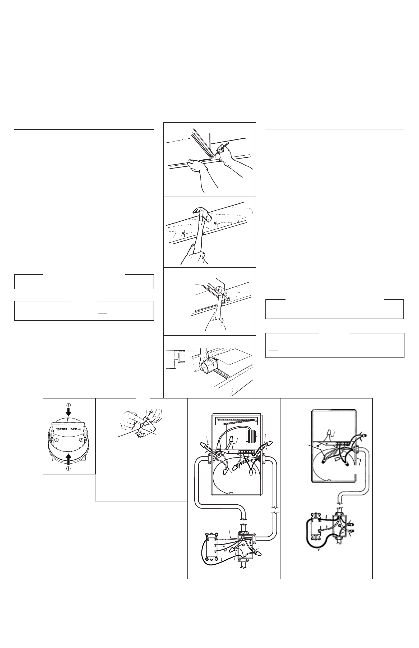
12. Snap the damper/duct connector onto housing. Make sure that tabs on the
connector lock in housing slots. (Top of damper/duct connector will be flush
with top of housing.) (FIG. 9)
NOTE: Make sure damper flap is in place inside of duct connector. If it is
not: Squeeze top and bottom of connector to snap flap back into place.
(FIG. 10)
Installation work and electrical wiring must be done by a qualified person(s)
in accordance with all applicable codes and standards, including fire-rated
construction codes and standards.
13. Wire unit according to Figure 11 or 12, whichever is appropriate. (See NOTE.)
STEP 14 - MODELS 655, 659 & 659F ONLY
14. Replace heater assembly removed in STEP 3 and plug it into RED receptacle.
Direct wires away from blower inlet.
15. Replace fan assembly removed in STEP 5 and plug it into BLACK receptacle.
CAUTION
To avoid the possibility of overheating and/or re, the grille must be
installed as shown in FIG. 13. Acorn nut must attach to threaded rod
through proper hole in light reector.
16. Slide the light reflector into opening in grille and plug into WHITE receptacle.
Use acorn nut from plastic bag to attach grille reflector assembly to threaded
rod on housing. Tighten securely using pliers or nut driver. Install a light
bulb 100 Watt maximum. (FIG.13)
17. Install light lens by 1) hooking one of its tabs into notch in grille/reflector
assembly; 2) apply light pressure to other tab with fingertips and 3) snap
into place. (FIG. 14)
INSTALACION
ADVERTENCIA: Para reducir el riesgo de incendio, no almacene ni use gasolina
u otros vapores y líquidos flamables en las cercanías del calentador.
PRECAUCIÓN: Temperatura alta, el riesgo de incendio, mantenga los cables
eléctricos, cortinas, muebles y otros materiales combustibles por lo menos
3 pies (0,9 m) del frente del calentador y lejos de la cara y la parte trasera.
8. Para mejores resultados, elija una posición que permita que el ventilador
extraiga hacia afuera usando la menor cantidad de ducto y el menor número
posible de codos.
9. Coloque la unidad entre las vigas y extienda los soportes de montaje. Coloque
los soportes de manera que el extremo inferior de la caja esté al nivel del cielo
raso acabado. Marque la parte superior de la ranura en los cuatro soportes
de montaje. (FIG. 5)
10. Saque la unidad por unos momentos, y clave los clavos parcialmente en las
vigas en las cuatro posiciones marcadas. (FIG. 7)
11. Cuelgue la unidad de los clavos y use las guías de medición estampadas para
comprobar si la unidad se encuentra a nivel con el cielo raso acabado. Termine
de clavar los clavos. En caso de que el centro de las vigas sea ancho: se puede
usar un tornillo autoenroscante # 8 x 3/8 para juntar los soportes extendidos
y crear un soporte de montaje rígido. Para asegurar un montaje silencioso,
pliegue los canales alrededor de los soportes de montaje. (FIG. 8)
12. Meta la conexión del amortiguador/ducto en la caja. Asegúrese de que las
lengüetas del conector se cierran en las ranuras de la caja.(La parte superior
del amortiguador/ducto debe estar a nivel con la parte superior de la caja).
(FIG. 9)
NOTA: Asegúrese de que la tapa del regulador de tiro esté colocada dentro del
conector del conducto. Si no lo está:
Comprima la parte superior e inferior
del conector para
volver a colocar la tapa en su lugar. (FIG. 10)
El trabajo de instalación y el cableado eléctrico deben estar a cargo de personal
capacitado, de acuerdo con todos los códigos y normas correspondientes,
incluidos los códigos y normas de construcción específicos sobre protección
contra incendios.
13. Conecte la unidad de acuerdo con el diagrama de las figuras 11 y 12. (Vea
NOTA.)
PASO 14 - SOLO PARA MODELOS 655, 659, Y 659F
14. Vuelva a colocar el conjunto del calentador que se sacó en el paso 3 y
conéctelo al enchufe ROJO. Instale los alambres alejados de la entrada de
aire el ventilador.
15. Vuelva a colocar el conjunto del ventilador que se sacó en el paso 5 y conéctelo
al enchufe NEGRO.
PRECAUCION
Para evitar la posibilidad de un sobrecalentamiento y/o un incendio, la
rejilla debe ser instalada se muestra en la gura 13. La tuerca ciega
debe conectarse a la varilla roscada a través del agujero apropiado en
el reector de luz.
16. Deslice el reflector de luz en la abertura de la rejilla y conéctelo al enchufe
BLANCO. Use la tuerca en la bolsa de plástico para sujetar la rejilla y el reflector
de luz a la varilla roscada de la caja. Apriete con fuerza usando el alicates o el
aprietatuercas. Instale una bombilla de un máximo de 100 vatios. (FIG. 13)
17. Para instalar el lente de la luz: 1) Enganche una de las lengüetas en la muesca
del conjunto rejilla/reflector; 2) Aplique un poco de presión a la otra lengûeta
con los dedos, y 3) Encájela en su sitio. (FIG. 14)
FIG. 6
FIG. 7
FIG. 8
EMBOSSED
MEASURING
GUIDES
GUIAS ESTAM-
PADAS DE
MEDICION
FIG. 9
FLUSH
NIVEL
NOTE
NOTA
WIRE
OPENING
ENTRADA
PARA
EL CABLE
RELEASE SLOT
RANURA DE
DESENGANCHE
If the switch has not been wired properly and wires need to
be moved:
1. Each wire opening has a release slot.
2. Push a small nail or screwdriver into release slot while gently
removing wire.
3. DO NOT pull any wire out of the switch without using the
release slot. The switch may be damaged.
Si el interruptor no ha sido conectado de forma apropiada y se
necesita cambiar los cables:
1. Cada entrada para cable posee una ranura de desenganche.
2. Meta un clavo pequeño o un destornillador en la ranura de
desenganche mientras saca el cable poco a poco.
3. NO tire de los cables hacia afuera del interruptor sin usar la
ranura de desenganche. Esto puede dañar el interruptor.
FIG. 10
FIG. 11 MODELS / MODELOS 655, 659
RED / ROJO
WHITE
BLANCO
BLACK
NEGRO
120 VAC LINE IN
LINEA DE ENTRADA DE 120 VCA
LIGHT
LUZ
VENT
RESPI-
RADERO
HEAT
CALOR
GROUND
TIERRA
RED
ROJO
BLACK
NEGRO
GROUND
TIERRA
RED
ROJO
BLUE
AZUL
WHITE
BLANCO
BLACK
NEGRO
LIGHT
LUZ
VENT
RESPIRADERO
WHITE
BLANCO
GRD
TIERRA
120 VAC LINE IN
LINEA DE ENTRADA DE
120VCA
BLACK
NEGRO
WHITE
BLANCO
BLACK
NEGRO
GRD
TIERRA
RED
ROJO
BLUE
AZUL
FIG. 12 MODEL / MODELO 657
BLACK
NEGRO
RED/ROJO
GROUND
TIERRA