User’s Guide


3
CONTENTS
Safety Instructions .................................................................................................................................. 4
Precautions ............................................................................................................................................. 6
Declaration of Conformity ........................................................................................................................ 7
Intro to PRX ONE ...................................................................................................................................... 8
PRX ONE - Block Diagram ..................................................................................................................... 10
PRX ONE - Application Examples ........................................................................................................... 11
PRX ONE - Mixer Panel ........................................................................................................................ 13
PRX ONE - Mixer Panel Functions........................................................................................................... 14
PRX ONE - EasyNav LCD ....................................................................................................................... 17
JBL Pro Connect App ............................................................................................................................. 31
Optional Accessories ............................................................................................................................. 32
PRX ONE - Specications .......................................................................................................................33
Cables & Connectors ............................................................................................................................. 34
Contact Information .............................................................................................................................. 35
Warranty Information .............................................................................................................................36

4
The PRX ONE covered by this manual is not intended for use in high moisture environments. Moisture can damage the
speaker cone and surround and cause corrosion of electrical contacts and metal parts. Avoid exposing the speakers to
direct moisture.
Keep speakers out of extended or intense direct sunlight. The driver suspension will prematurely dry out and nished
surfaces may be degraded by long-term exposure to intense ultra-violet (UV) light. The PRX ONE can generate
considerable energy. When placed on a slippery surface such as polished wood or linoleum, the speaker may move due
to its acoustical energy output. Precautions should be taken to assure that the speaker does not fall off a stage or table
on which it is placed.
HEARING DAMAGE, PROLONGED EXPOSURE TO EXCESSIVE SPL
The PRX ONE is capable of generating sound pressure levels (SPL) sufcient to cause permanent hearing damage to performers, production
crew, and audience members. Caution should be taken to avoid prolonged exposure to SPL in excess of 85 dB.
CARE & CLEANING
PRX ONE may be cleaned with a dry cloth. Do not allow moisture into any of the openings in the system. Ensure that the system is
unplugged from the AC outlet before cleaning.
THIS APPARATUS CONTAINS POTENTIALLY LETHAL VOLTAGES. TO PREVENT ELECTRIC SHOCK OR HAZARD, DO NOT REMOVE CHASSIS,
MIXER MODULE, OR AC INPUT COVERS. NO USER-SERVICEABLE PARTS INSIDE. REFER SERVICING TO QUALIFIED SERVICE PERSONNEL.
WEEE Notice
The Directive 2012/19/EU on Waste Electrical and Electronic Equipment (WEEE), which entered into force as European law
on 14/02/2014, resulted in a major change in the treatment of electrical equipment at end-of-life. The purpose of this Directive
is, as a rst priority, the prevention of WEEE, and in addition, to promote the reuse, recycling and other forms of recovery of such
wastes so as to reduce disposal. The WEEE logo on the product or on its box indicating collection for electrical and electronic
equipment consists of the crossed-out wheeled bin, as shown below.
This product must not be disposed of or dumped with your other household waste. You are liable for disposing of all your electronic
or electrical waste equipment by relocating over to the specied collection point for the recycling of such hazardous waste. Isolated
collection and proper recovery of your electronic and electrical waste equipment at the time of disposal will allow us to help conserve
natural resources. Moreover, proper recycling of the electronic and electrical waste equipment will ensure the safety of human health and
environment. For more information about electronic and electrical waste equipment disposal, recovery, and collection points, please contact
your local city center, household waste disposal service, shop from where you purchased the equipment, or manufacturer of the equipment.
RoHS Compliance
This product is in compliance with Directive 2011/65/EU and (EU) 2015/863 of the European Parliament and of the Council of 19.
31/03/2015 on the restriction of the use of certain hazardous substances in electrical and electronic equipment.
SAFETY INSTRUCTIONS
5
1. READ these instructions.
2. KEEP these instructions.
3. HEED all warnings.
4. FOLLOW all instructions.
5. DO NOT use this apparatus near water.
6. CLEAN ONLY with dry cloth.
7. DO NOT block any ventilation openings. Install in accordance with the manufacturer’s instructions.
8. DO NOT install near any heat sources such as radiators, heat registers, stoves, or other apparatus (including ampliers) that
produce heat.
9. DO NOT defeat the safety purpose of the polarized or grounding type plug. A polarized plug has two blades with one wider
than the other. A grounding type plug has two blades and a third grounding prong. The wider blade or the third prong are
outlet.
10. PROTECT the power cord from being walked on or pinched, particularly at plugs, convenience receptacles, and the point
where they exit from the apparatus.
11. ONLY USE attachments/accessories specied by the manufacturer.
12.
USE ONLY with a cart, stand, tripod, bracket, or table specied by the manufacturer, or sold with the apparatus.
When a cart is used, use caution when moving the cart/apparatus combination to avoid injury from tip-over.
13. UNPLUG this apparatus during lightning storms or when unused for long periods of time.
14. REFER all servicing to qualied service personnel. Servicing is required when the apparatus has been damaged in any
way, such as power-supply cord or plug is damaged, liquid has been spilled or objects have fallen into the apparatus, the
apparatus has been exposed to rain or moisture, does not operate normally, or has been dropped.
15. DO NOT expose this apparatus to dripping or splashing and ensure that no objects lled with liquids, such as vases, are
placed on the apparatus.
16. To completely disconnect this apparatus from the AC Mains, disconnect the power supply cord plug from the AC receptacle.
17. Where the mains plug or an appliance coupler is used as the disconnect device, the disconnect device shall remain readily
operable.
18. DO NOT overload wall outlets or extension cords beyond their rated capacity as this can cause electric shock or re.
19. For adequate ventilation, do not install this equipment in a conned or enclosed space.
20. Product ventilation should not be impeded by covering the ventilation openings with items such as newspaper, tablecloths,
curtains, etc.
The lightning ash with an arrowhead symbol within an equilateral triangle is intended to alert the user to the presence
of uninsulated “dangerous voltage” within the product’s enclosure that may be sufcient in magnitude to constitute a
risk of electrical shock to persons.
The exclamation point, within an equilateral triangle, is intended to alert the user to the presence of important operating
and maintenance (servicing) instructions in the literature accompanying the product.
WARNING: To reduce the risk of re or electrical shock, do not expose this apparatus to rain or moisture.
WARNING: No naked ame sources – such as lighted candles –should be placed on the product.
WARNING: Equipment shall be connected to a MAINS socket outlet with a protective earthing connection.
6
WARNING: This product is intended to be operated ONLY from the voltages listed on the back panel. Operation from other voltages other
than those indicated may cause irreversible damage to the product and void the product’s warranty. The use of AC Plug Adapters is cautioned
because it can allow the product to be plugged into voltages in which the product was not designed to operate. If you are unsure of the
correct operational voltage, please contact your local distributor and/or retailer. If the product is equipped with a detachable power cord, use
only the type provided, or specied, by the manufacturer or your local distributor.
OPERATING TEMPERATURE RANGE: -10C - 45C (14F - 113F)
WARNING TO REDUCE THE RISK OF ELECTRIC SHOCK,
DO NOT EXPOSE THIS EQUIPMENT TO RAIN OR MOISTURE.
RISQUE DE CHOC ELECTRIQUE NE PAS OUVRIR
WARNING: Do Not Open! Risk of Electrical Shock. Voltages in this equipment are hazardous to life. No user-serviceable parts inside. Refer
all servicing to qualied service personnel.
Place the equipment near a main power supply outlet and make sure that you can easily access the power breaker switch.
FCC AND CANADA EMC COMPLIANCE INFORMATION: This device complies with Part 15 of the FCC Rules. Operation is subject to
the following two conditions
1. This device may not cause harmful interference, and (2) this device must accept any interference received, including interference that
may cause undesired operation.
CAUTION: Changes or modications not expressly approved by the manufacturer could void the user’s authority to operate this device.
NOTE: This equipment has been tested and found to comply with the limits for a Class B digital device, pursuant to Part 15 of the FCC
Rules. These limits are designed to provide reasonable protection against harmful interference in a residential installation. This equipment
generates uses and can radiate radio frequency energy and, if not installed and used in accordance with the instructions,
may cause harmful interference to radio communications. However, there is no guarantee that interference will not occur in a particular
installation. If this equipment does cause harmful interference to radio or television reception, which can be determined by turning the
equipment off and on, the user is encouraged to try to correct the interference by one or more of the following measures: Reorient or relocate
the receiving antenna. Increase the separation between the equipment and receiver. Connect the equipment into an outlet on a circuit different
from that to which the receiver is connected. Consult the dealer or an experienced radio/TV technician for help.
CAUTION: This product is for non-residential use only.
WARNING: This equipment is compliant with Class B of CISPR 32. In a residential environment this equipment may cause radio
interference.
CAN ICES-003(B)/NMB-003(B)
Protective earthing terminal. The apparatus should be connected to a mains socket outlet with a protective earthing connection.
PRECAUTIONS

7
DECLARATION OF CONFORMITY
WIRELESS TRANSMITTER COMPLIANCE INFORMATION: The term “IC:” before the radio certication number only signies that
Industry Canada technical specications were met.
Le terme «IC:» avant le numero de certication radio signie seulement que les specications techniques d’lndustrie Canada ont ete
respectees.
This device contains licence-exempt transmitter(s)/receiver(s) that comply with Innovation, Science and Economic Development
Canada’s licence-exempt RSS(s). Operation is subject to the following two conditions (1) this device may not cause harmful
interference, and (2) this device must accept any interference, including interference that may cause undesired operation of the device.
Cet appareil contient des émetteurs / récepteurs exemptés de licence conformes aux RSS (RSS) d’Innovation, Sciences et
Développement économique Canada. L’exploitation est autorisee aux deux conditions suivantes : (1) l’appareil ne doit pas produire
de brouillage, et (2) l’utilisateur de l’appareil doit accepter tout brouillage radioelectrique subi, meme si le brouillage est susceptible
d’en compromettre le fonctionnement.
This equipment complies with FCC and IC radiation exposure limits set forth for an uncontrolled environment. This equipment should
be installed and operated with minimum distance 20cm between the radiator and your body. This transmitter must not be co-located or
operating in conjunction with any other antenna or transmitter.
Cet appareil est conforme a FCC et IC !’exposition aux rayonnements limites xees pour un environnement non controle. Cet appareil
doit etre installe et utilize avec une distance minimale de 20cm entre le radiateur et votre corps. Cet transmetteur ne doit pas etre cositue
ou operant en liaison avec toute autre antenne ou transmetteur.
EU COMPLIANCE INFORMATION:
Hereby, HARMAN Professional, Inc., declares that the equipment type PRX ONE is in compliance to the following:
European Union Restriction of Hazardous Substances Recast (RoHS2) Directive 2011/65/EU; European Union WEEE (recast)
Directive 2012/19/EU; European Union Registration, Evaluation, Authorization and Restriction of Chemicals (REACH) Directive
1907/2006; European Radio Equipment Directive (RED) 2014/53/EU
You may obtain a free copy of the full Declaration of Conformity by visiting:
http://www.jblpro.com/www/product-support/downloads
This product contains batteries that are covered under the 2006/66/EC European Directive, which cannot be disposed of with normal
household waste. Please follow local regulations.
WIRELESS FREQUENCY RANGE AND WIRELESS OUTPUT POWER:
2402MHz - 2480MHz
10.00mW
Prevention of hearing loss
Caution: Permanent hearing loss may occur if earphones or headphones are used at high volume for prolonged periods of time.
Note: To prevent possible hearing damage, do not listen at high volume levels for long periods.
CLASS B PRODUCT:
ENVIRONMENTAL:
此标识适用于在中华人民共和国销售的电子信息产品 . 标识中间的数字为环保实用期限的年数 .
8
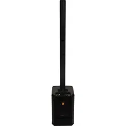
INTRO TO PRX ONE
GETTING STARTED
Congratulations on your purchase of JBL Professional PRX ONE loudspeakers! We know you are anxious to get up and running as
fast as possible, which is why you are reading this section. The following will help you get set up as soon as possible.
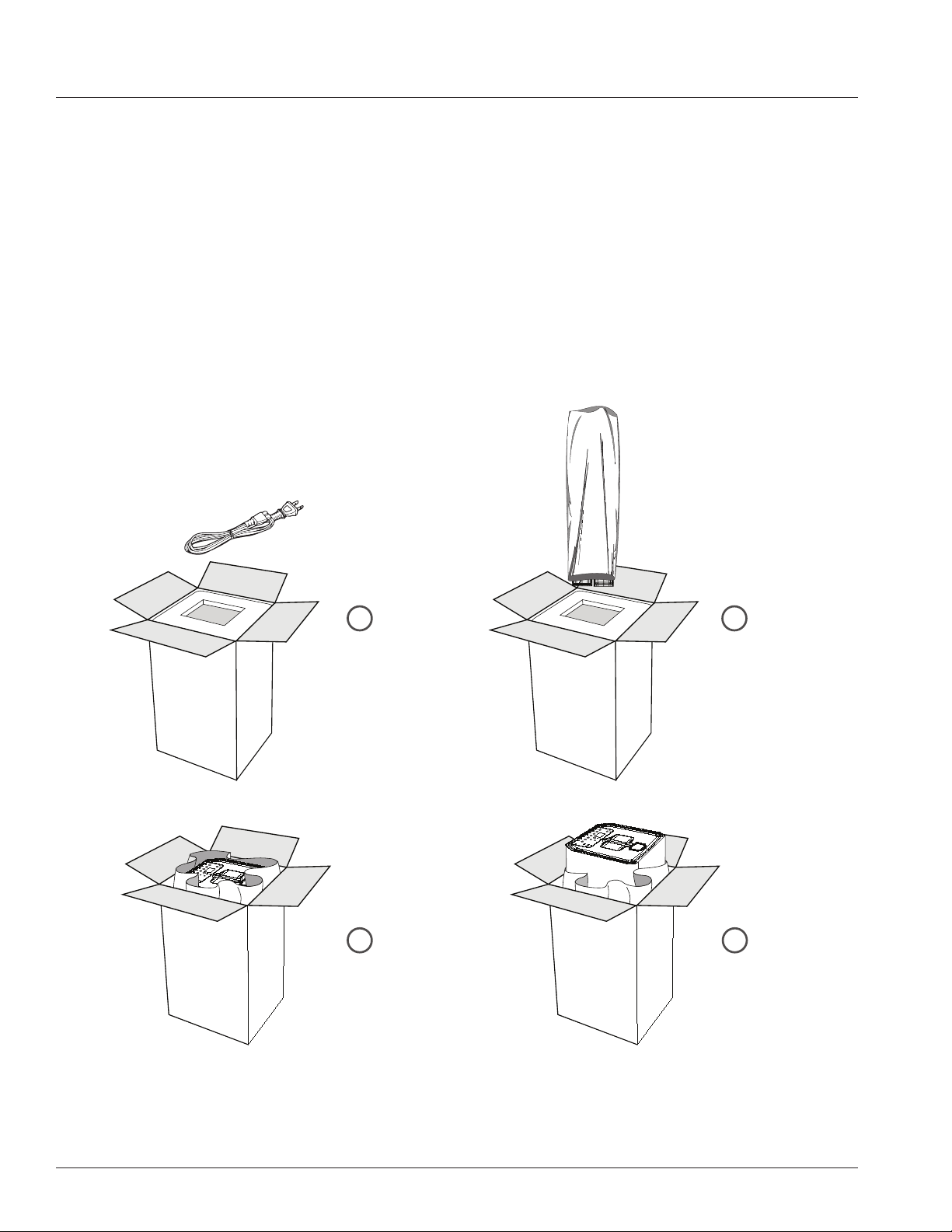
Packaging Contents
Your PRX ONE should include the following:
• 1 PRX ONE Woofer Cabinet
• 2 PRX ONE Linear Arrays
• 1 PRX ONE Linear Array bag
• 1 10’ (3m) AC Power Cable
• 1 Quick Start Guide
Unboxing
1 2
3 4
Open unit, pull AC
cable from top box
and remove
Open plastic to expose
woofer handle
Remove woofer
Remove linear array
unit in bag
9
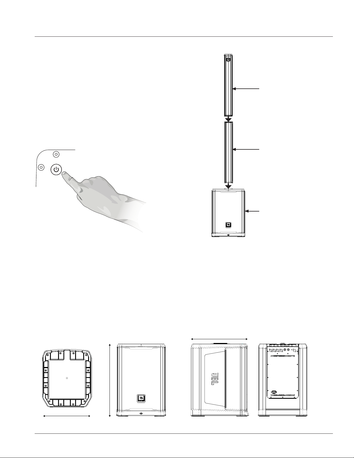
SETTING UP
How to set up
• Plug Linear Array B into the Woofer Cabinet
• Plug Linear Array A into Linear Array B
• Connect AC power inlet
How to turn on/off
• Turn on unit by short pressing the power button until the LCD res on
• Turn off the unit by HOLDING power button for 3s until unit turns off
P.A. BASICS
A mixing board is actually a very simple device that takes the audio input signals (from the input channels) and “mixes” them to
the outputs. The mixing board controls will typically enable the user to blend the input channel signal levels, affect their tone,
and adjust each channel’s reverb level. The signal is then fed from the mixing board to the ampliers and onto the speakers. The
PRX ONE is a self-contained PA system, which includes a mixing board, ampliers, and speakers.
GETTING ACQUAINTED WITH PRX ONE
The powered mixer section of the PRX ONE system houses the mixing board and power amplifier. Here, all of the
microphones, musical instruments, and external sound sources (such as MP3 players, CD players, or Bluetooth audio
sources) can be connected.
Bottom View Front View Left View Rear View
486
446
375
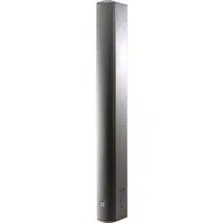
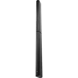
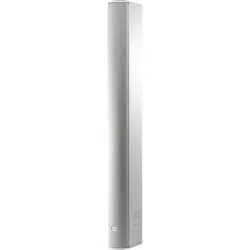
Linear Array A
Linear Array B
Woofer
10
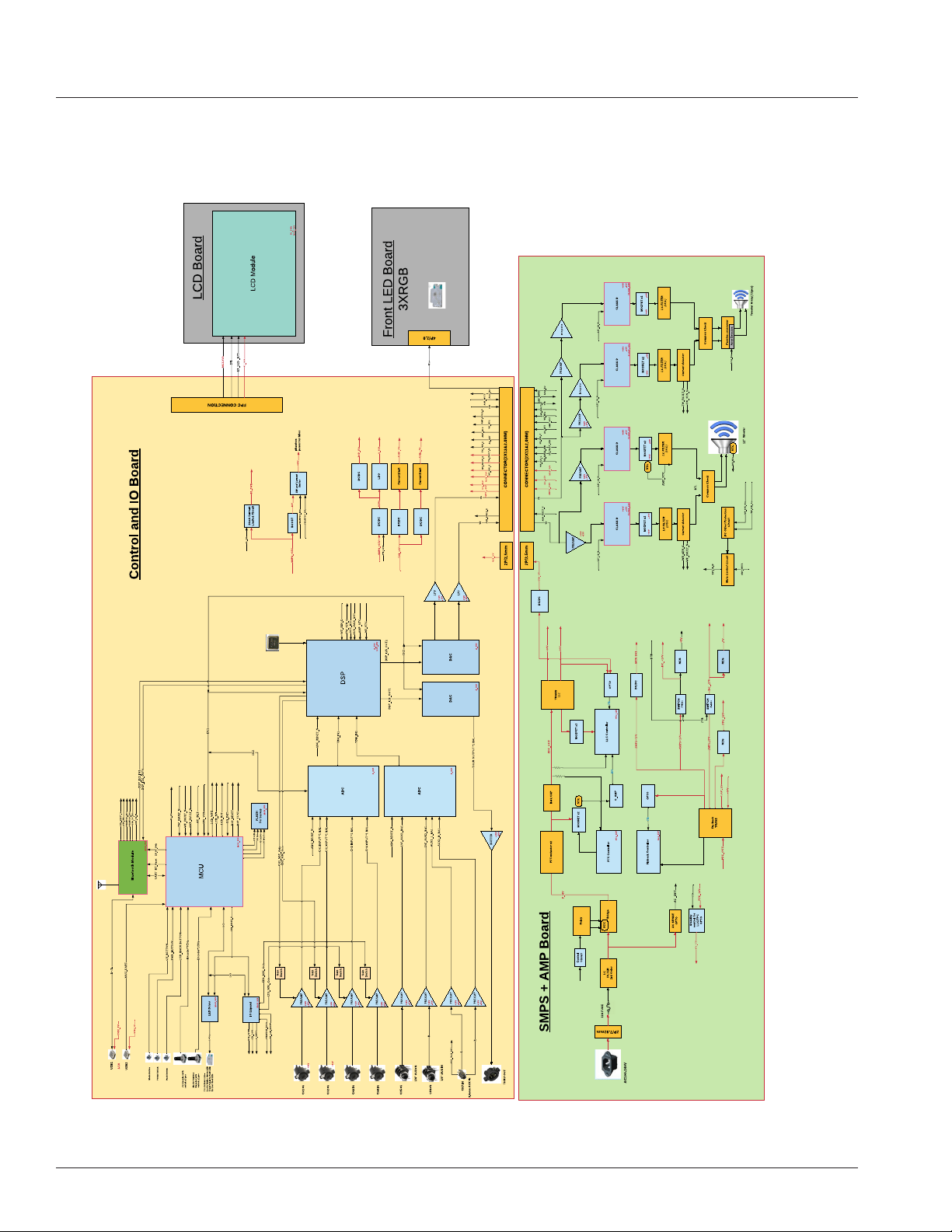
BLOCK DIAGRAM
11
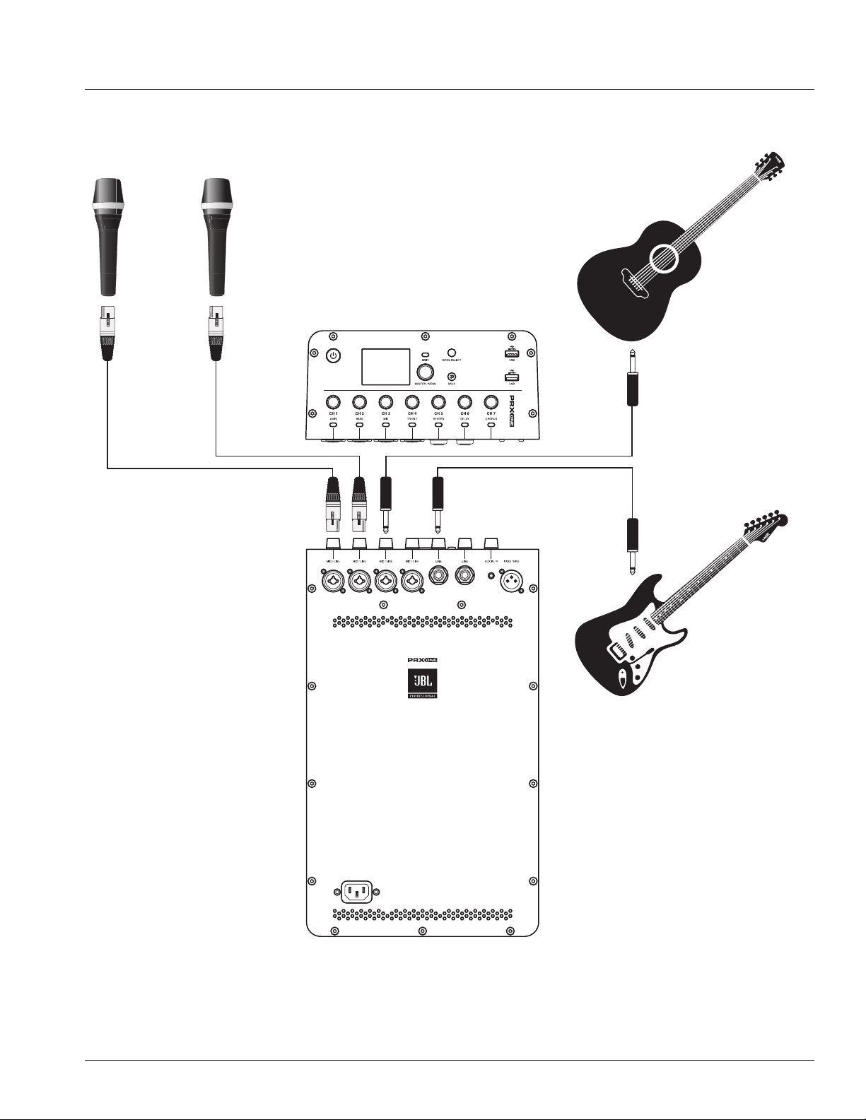
CONDENSER
MICROPHONE
MULTIPLE INSTRUMENTS/MICS PLUGGED INTO MIXER
CH1 XLR-1/4” Combo Condenser Mic, CH2 XLR-1/4” Combo Mic, CH3 Passive Pickup Guitar, CH5 Active Pickup Guitar
APPLICATION EXAMPLES
12
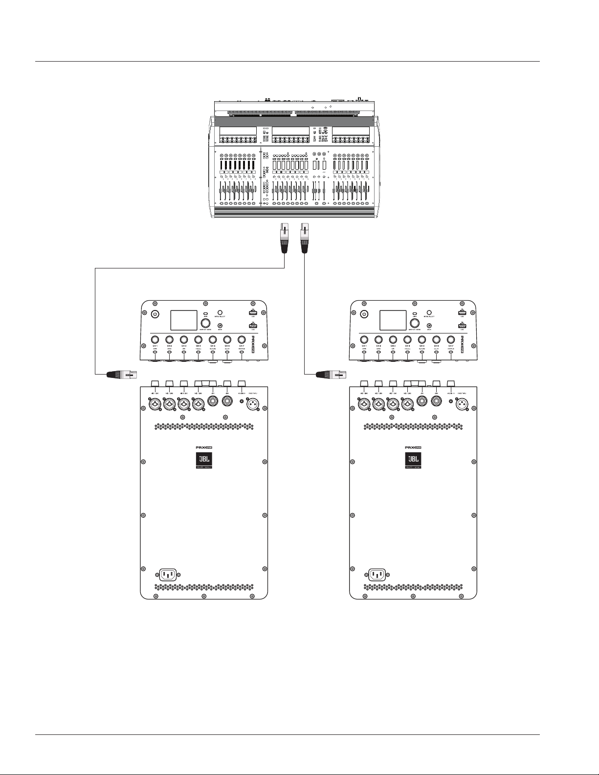
USING TWO SYSTEMS AS MONITORS
PRX ONE Left and PRX ONE Right
13
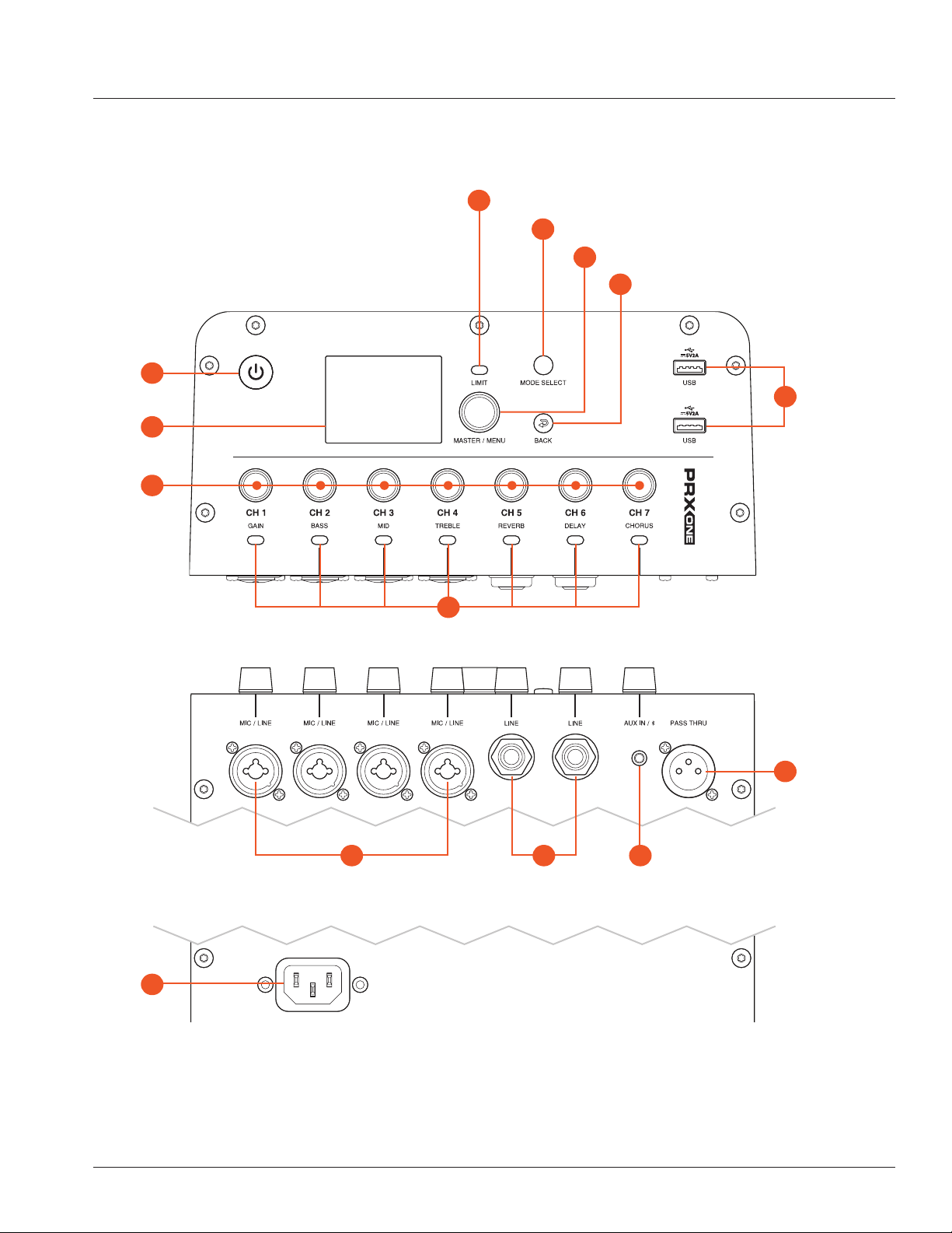
MIXER PANEL
A
B
C
J
K
D
L M
E
F
G
H
I
N
Power
Button
LCD
Display
Mixer
Knobs
Dynamic LEDs
Power
Inlet
USB
Ports
Limit LED
Mix/Channel Mode Select
Master Volume/Menu Encoder
Back Button
XLR Male
Pass Thru
XLR-1/4”
Combo
6.35mm Hi-Z
Balanced Input
3.5mm Stereo
Un-Balanced Input

14
A. Power Button
The Power Button is a momentary push button. It is used to toggle the unit between the On and Off states. When in the
Off state, a short press and release of the Power Button will put the unit into the On state.
B. LCD Display
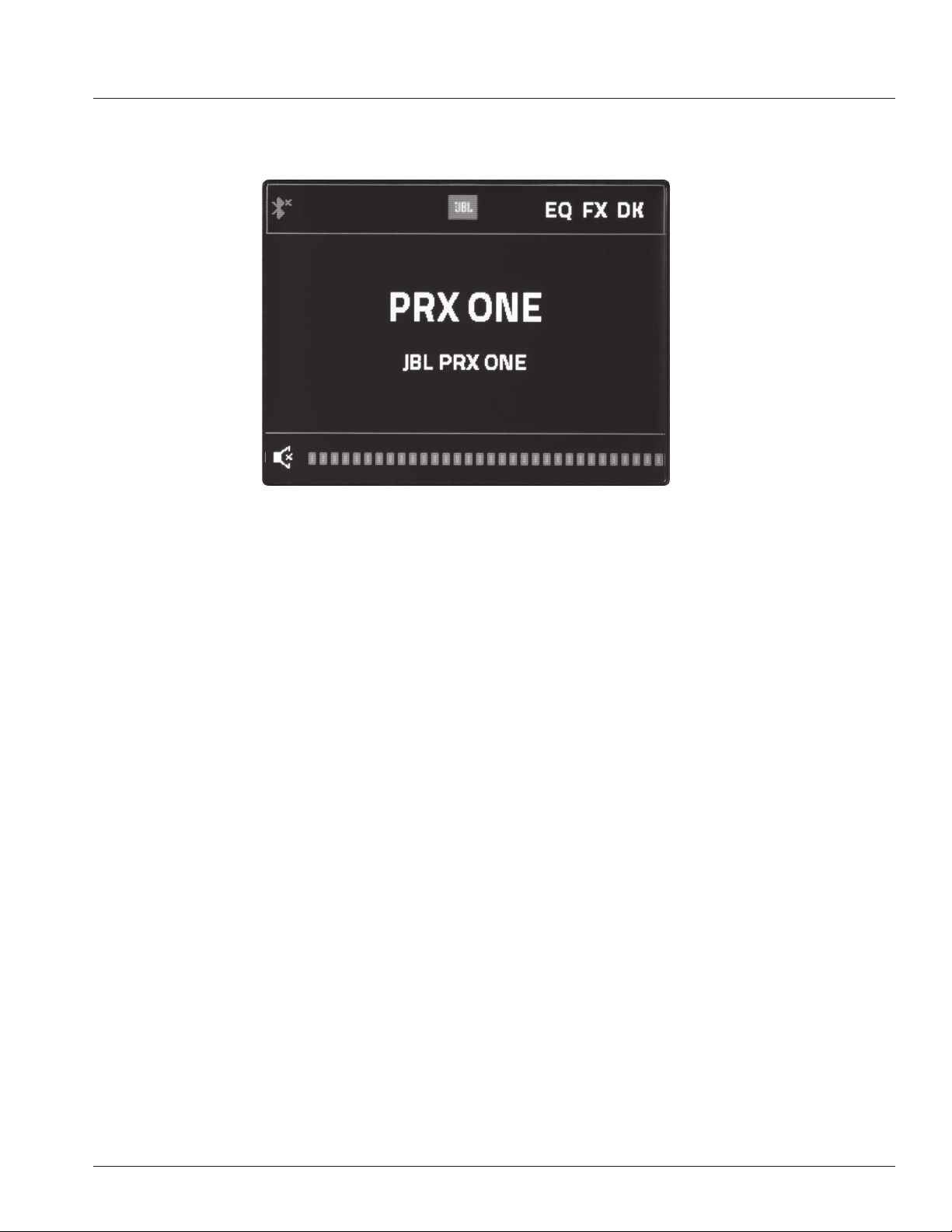
The LCD is used to display basic diagnostic information and allow access to more advanced features through a menu system.
See the LCD GUI specication for more details on the LCD menu system, features, and navigation. The LCD will refresh at
approximately 4Hz and is not suitable for meters or any other fast motion items.
C. Mixer Mode
Adjust the channel input level
Channel Strip Mode: Adjust the listed channel parameter for the selected channel
D. Dynamic LEDs
Channel level represented by colors
Channel Strip Mode: Denotes the selected channel
E. Limit LED
Amplier is reaching clip.
F. Mix / Channel Mode Select
PRX ONE has 2 unique operation modes of the mixer which can be toggled using the MODE Select button or by pressing a
specic channel rotary:
• Mix Mode
• Channel Strip mode
G. Master Volume / Menu Encoder
Controls LCD Display
• Rotary encoder: In Menu - Clockwise down menu/Anti-clockwise up menu
• Press to select menu item
• On Home screen, Master Level increase by rotating the knob clockwise.
• On Home screen, Master Level decrease by rotating the knob counterclockwise. Master encoder with detent: 70+/-40gf.cm
H. Back Button
Press to return to previous menu item
I. USB Ports
• USB Type-A
• Standard USB2.0 Type-A port
• Connecting with device: Charging 2.0 (x2 USB)
• Connecting with PC or USB stick for SW/FW upgrade (x1 USB)
J. Power Inlet
Rear panel LED to indicate power, and colour denotes Sleep/Active
K. XLR-1/4” Combo Inputs
Four female XLR – 1⁄4” combination connectors (1 for each input) are used for the analog audio inputs.
MIXER PANEL FUNCTIONS

15
CH 1-2
• Phantom Power disclaimer
When using condenser microphones, +48V phantom power is required to be present at the contacts of the
microphone (XLR) connector for the microphone to operate correctly. When phantom power is enabled, it is applied to
both the CH1 and CH2 XLR inputs. Ensure that phantom power is off when not required.
To prevent damage to the PRX ONE or external devices when using condenser microphones, always turn down all PRX
ONE output controls and ensure the +48V phantom power is off before connecting the microphone. Once the condenser
microphone has been connected, enable the +48V phantom power, then raise the output controls to the desired levels.
1. The PRX ONE offers user-selectable phantom power on both channels 1 and 2, turned on via the LCD or the APP.
a. To engage phantom power, press the knob for CH1 or CH2 to open the Channel Menu.
b. Navigate to Phantom Power and press the Master/Menu knob.
Knobs and Functions
The PRX ONE comes equipped with push-button rotaries to make for easy navigation and hardware usage.
1. A single press of a Channel knob will activate CHANNEL STRIP MODE for that channel.
a. Please see the section on CHANNEL STRIP MODE for more clarity.
2. Pressing and holding a CH knob for 2s at any time will mute that channel. Channel LED below muted channel will
slowly ash RED.
3. A single press of the MASTER/MENU knob will open up the master menu, unless you are in a channel menu
screen. In channel menu screens, the MASTER/MENU knob controls your main navigation through these screens.
4. Pressing and Holding MASTER/MENU while on the home page will mute the speaker.
L. 6.35mm Hi-Z Balanced Input
Two female 6.3mm connectors (1 for each input) are used for the analog audio inputs.
M. 3.5mm Stereo Un-Balanced Input
Two channel single ended input, mono mixed as a single mixed channel.
N. XLR Male Pass Thru
This XLR (male) output connector provides a method of sending audio out to an external source. If signal is present on all inputs, the
inputs will be summed and sent out as a mix: Can be adjusted in the pass through menu section.

16
Buttons and Functions
1. The MODE SELECT button will swap between MIX MODE and CHANNEL STRIP MODE. For more on these
modes, please see their respective sections in the guide.
2. The BACK button will back you out of the current screen you are in without saving changes. This can be thought
of as a “CANCEL” button.
Mix Mode
1.
Press “Mode Select” button
a. All LEDs will turn ON, indicating you’ve successfully initiated Mix Mode
2. In mix mode, the knobs will now control their respective channel gains. For example, twisting the knob
labeled CH1 will increase the gain of CH1.
3. PRX ONE has an automatic mic/line switch. Between-100dB and 0dB, the channel will be in LINE mode.
Between 1dB and 56dB, the channel will be in MIC mode.
Channel Strip Mode
1.
Access Channel Strip mode in one of two ways
a. When in mix mode, press the “Mode Select” button. A single CH LED will light, indicating you are in
Channel Strip Mode. The default CH and LED selection will revert to last known state, or the last channel
you were editing in CHANNEL STRIP MODE.
b. Press the rotary knob of the channel you wish to edit.
2. When in Channel strip mode, the knobs control the respective listed function of the selected channel (i.e. Gain,
Bass, Mid, Treble, Reverb Send, Delay Send, Chorus Send)
LEDs and Functions
1. Signal detection - LED below channel knobs will periodically flash yellow to indicate signal is present.
2. LED function when Muting Channels/Speaker : LED Below Channel knobs will slowly ash RED when a channel
is muted.
17
Master Menu
1. Pressing the Master/Menu rotary at any time will take you to the PRX ONE’s master menu. Here, users can
access the main menu functions of the PRX ONE
2. Ducking by Soundcraft” is a type of side-chain compressor most often used to lower the level of music playback
while a person is talking into a microphone. This feature allows the user to choose which mic channels to use
as sensors, the sensitivity of each channel, and the amount of music reduction while a person is speaking. This
menu engages the ducking feature, allows users to select which channel(s) will act as the trigger for ducking, and
set individual thresholds of each channel.
a. To access this menu, navigate to ducking and press the Master/Menu button.
b. To turn on ducking, navigate to Ducking and press the Master/Menu button
i. Turn the knob CLOCKWISE to activate ducking
ii. Turn the knob COUNTER-CLOCKWISE to disable ducking
c. “Channel Sensors” give the user the option to select which mic inputs can be used to trigger the Bluetooth
playback music ducking. The user can select any combination of the mic inputs to turn on as sensors for
Bluetooth music ducking.
i. To adjust the Channel Sensor, navigate to the Channel Sensor eld and press the Master/Menu button
. Navigate to the respective channel(s) you wish to set as a sensor and press the Master/Menu
button
. Turn the knob CLOCKWISE to activate that channel as a SENSOR for ducking. When this is
selected, the respective channel will detect signal and activate the ducking feature on CH7.
. Turn the knob COUNTER-CLOCKWISE to disable that channel as a SENSOR for ducking. When
this is disabled, signal detection on this channel will NOT trigger the ducking feature on CH7.
d. “Sensitivity Parameters” give the user the option to select at what volume level each mic input channel will
EASYNAV LCD
Intro to the EasyNav LCD

18
trigger the ducker threshold. Stronger voices may want a higher sensor level. Weaker voices may want a
lower sensor level to trigger the music reduction. A lower value represents a less sensitive signal detection.
i. Select and edit these values by pressing the Master/Menu knob while Sensitivity Parameters is
highlighted.
. Navigate to the respective channel you wish to edit and press the Master/Menu knob to select.
. Adjust the parameter.
. Press the Master/Menu knob to save the adjustment
. Press the BACK button to cancel this adjustment.
ii. Range is a parameter that tells CH7 how much volume should be reduced when signal detection
meets the desired level.
. To adjust this, navigate to RANGE and press the Master/Menu knob.
. Adjust the parameter
. Press the Master/Menu knob to save the adjustment
. Press the BACK button to cancel this adjustment.
iii. Release Time is a parameter that tells CH7 when it should return to normal volume after signal is no
longer detected. This value is represented in ms (milliseconds).
. To adjust this, navigate to RELEASE TIME eld and press the Master/Menu knob.
. Adjust the parameter
. Press the Master/Menu knob to save the adjustment
. Press the BACK button to cancel this adjustment.

19
.
3. FX Processing is where users access the effects parameters, minus sends, of the Lexicon effects engine.
a. The PRX ONE offers a Lexicon effects engine that provides users with Reverb, Delay, Chorus and
Sub-synth effects.
i. Navigate to the FX Processing menu in the Master/Menu and press the knob to access.
ii. Here you will be able to turn the effect on/off, edit the main parameters of the effect and access
presets.
b. Reverb by Lexicon Parameters
i. “On/Off”
. When set to off, the Reverb by Lexicon input is disabled. When turning this off while active, the
current reverb sound will continue to ring out. To reduce it immediately, reduce the Level To Mix
setting.
ii. “Reset” will set the Reverb by Lexicon to off and adjust the settings to “Room Medium” default preset,
to start over as a factory default.
iii. “Presets” offers users a selection of common settings for fast selection in typical use cases. These
reverb settings are named as descriptions of the types of rooms or halls they simulate.
. Presets assist new users wanting to try quick examples of often-used reverb setting
combinations.
. The user can select “Custom” and adjust all the settings themselves. Or they can start with
one of the location description presets, listen, and then add any settings adjustments, which
automatically load the new combination of settings into the “Custom” setting for further
adjustments.
. Custom
. Room Small
. Room Medium

20
. Room Medium Bright
. Room Large
. Hall Medium
. Hall Medium Bright
. Hall Large
iv. The combination of “Size” and “Pre-delay Time” dene the reverb simulation in just two controls;
how big the room is (Size) and how far away the audience member feels they are in regard to the
performers.
. Size adjusts the theoretical size of the simulated room in short, medium, long or longer.
. Pre-delay simulates the ratio of time from the source signal to the listener to the delay of the
rst reection off the closest wall.
. A shorter pre-delay time will make the audience feel farther away from the source
. A longer pre-delay time will make the audience feel closer to the source.
v. The High Frequency parameter simulates how much high-frequency reections are in the reverb.
. Simulating the sound of a room with many metal or glass surfaces is an example of a scenario
with more high-frequency reections.
. Simulating the sound of a room with soft word or outdoor settings would be an example of less
high-frequency reections.
vi. The Low frequency parameter simulates the amount of bass building in the reverb.
. An indoor, hard surface room will accumulate more bass build-up.
. An outdoor simulation would generate less bass build-up.
vii. The Level to Mix Parameter is the amount of wet signal (or signal with reverb) that is sent back to
your main mix.
. Increasing the level to mix will create a more prominent reverb effect.
. Decreasing the level to mix will create a more subtle reverb effect.
viii. To adjust any parameter, navigate to the parameter using the MASTER/MENU knob. Press the
MASTER/MENU knob to access.
. Adjust the values by turning the knob CLOCKWISE or COUNTER-CLOCKWISE.
. Press the MASTER/MENU knob to accept these changes. Press the BACK button to cancel
these changes.
c. Delay - The FX Processing Delay is designed to be a musically oriented delay, commonly used on rock and
ballad vocals and guitars. It is often set to match the specic “Beats Per Minute” (i.e. “BPM) of the song
currently being performed, plus how many delay returns are desired per beat, how long the delay keeps
returning and if the delay feeds back again multiple times.
i. “On/Off” When set to off, the Delay input is disabled. This allows the current signal to “ring out” until
the current delay signal is completed. To end the delay immediately, turn down the Delay Level to Mix
fader.

21
ii. “Reset” will set the Delay processing settings to default settings.
iii. “Presets” offers a quick selection of common settings for fast selection in typical use cases. These
delay settings are named as descriptions of the types of common musical uses they simulate. Presets
can assist new users wanting to try quick examples of often-used delay setting combinations. The
user can select “Custom” and adjust all the settings themselves. Or they can start with one of the
location description presets, listen, and then adjust any settings desired. When a user has selected
a preset and then adjusts a setting, all current delay settings are loaded into the Custom preset for
further editing.
. Custom
. Simple Quarters
. Simple Eights
. Simple Triples
. Simple 1:1
. Staggered Echo
. Bounce wall
. Fast Spring
iv. “Beats Per Minute” enters the beats per minute tempo of the song planned or in progress. The
speaker automatically calculates the delay times to match the beats per minute song tempo.
v. “SubDivision” enables the user to enter the number of times the delay returns the signal per beat. For
example, if this is set to “1:2” then for every beat there are two delay returns heard.
vi. “Delay Length” is the setting showing how long, represented in milliseconds (ms), the delays will
continue returning for each beat. The smaller the number, the faster the delay returned signal will fade
out per beat.
vii. “Feedback” is the amount of the delayed signal that is fed back into the Delay processor input, to
give more depth to the delay sounds.
viii. “Low Pass Filter” can be set to reduce the relative level of high frequencies of the delay returned
signal. If the user perceives bright high-frequency harshness resulting from very bright source signals,
this setting can be lowered to compensate.
ix. “Level to Mix” sets the amount of nal delay signal that contributes to the FX Return fader.
. To adjust any parameter, navigate to the parameter using the MASTER/MENU knob. Press the
MASTER/MENU knob to access.
. Adjust the values by turning the knob CLOCKWISE or COUNTER-CLOCKWISE.
. Press the MASTER/MENU knob to accept these changes. Press the BACK button to
cancel these changes.
d. Chorus - The FX Processing Chorus is designed to add a musically oriented light shimmer on rock or
ballad vocals and acoustic guitars. Chorus is often used very lightly to enhance the harmonic content and
character, to bring out more shine on pure wave types of natural musical sources.

22
i. “On/Off” When set to off, the Chorus input is disabled. This allows the current signal to “ring out”
until the current Chorus signal is completed. To end the Chorus process result immediately, turn
down the Chorus Level to Mix fader.
ii. “Reset” will set the Chorus processing settings to default settings.
iii. “Presets” offers users a quick selection of common setting combinations for fast selection in typical
use cases. These Chorus presets are named as descriptions of the types of common musical uses
they simulate. The user can select “Custom” and adjust all the settings themselves. Or they can
start with recalling one of the presets, listen, and then add any settings adjustments, which will
automatically load the new combination of settings into the “Custom” setting for further editing.
. Custom
. Slow Light
. Slow Deep
. Fast Light
. Fast Deep
. Smooth Vibrato
. High Pass
. Medium Narrow
iv. “Rate” adjusts the speed of vibration of the chorus effect.
v. “Depth” adjusts the length of time the chorus process takes to ring out over time.
vi. “Width” adjusts how wide the chorus process resonates above the source frequencies.
vii. “Level to Mix” is the amount of the Chorus signal sent to the FX Return fader, which then contributes
to the nal mix.
. To adjust any parameter, navigate to the parameter using the MASTER/MENU knob. Press the
MASTER/MENU knob to access.
. Adjust the values by turning the knob CLOCKWISE or COUNTER-CLOCKWISE.
. Press the MASTER/MENU knob to accept these changes. Press the BACK button to cancel
these changes.
e. Subsynth - The FX Processing SubSynth generates a complimentary bass note one octave below the
current input music. The SubSynth effect is often used on music to add a very deep low frequency bass
effect in line with the musical source feeding the SubSynth processor, instead of a general raise in bass EQ
frequencies using EQ bands. SubSynth is relative to the incoming musical content.
i. “On/Off” turns on/off the input to the SubSynth processor.
ii. “Level to Mix” sets how much of the SubSynth result is fed to the FX Return fader, which then feeds
the master mix fader.
iii. To adjust any parameter, navigate to the parameter using the MASTER/MENU knob. Press the
MASTER/MENU knob to access.
. Adjust the values by turning the knob CLOCKWISE or COUNTER-CLOCKWISE.
. Press the MASTER/MENU knob to accept these changes. Press the BACK button to cancel
these changes.
23
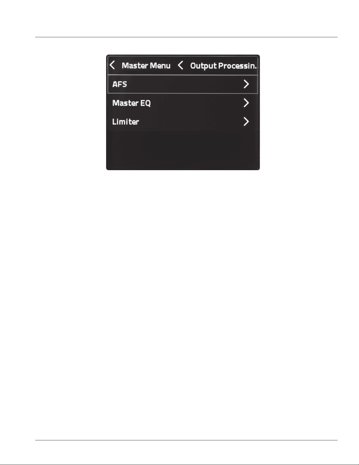
4. dbx DriveRack Output is a line of hardware products produced by Harman’s dbx brand. These rack mount signal
processors provide detailed control for nal processing and crossovers before feeding the mix to one or more
speakers. This DriveRack functionality embedded into PRX ONE is designed to optimize the combination of
speaker and Pass Thru outputs built into this JBL speaker.
a. AFS, or Automatic Feedback Suppression, is a combination of processing that can enable the user to add
up to 3 dB more total gain to their output before getting audio feedback back in through the mix inputs. dbx
AFS does this using a combination of auto-sensing and very tight width parametric EQs before the output
master EQ. Locked lters can be setup before an event as “xed” lters. Plus live AFS lters can be turned
on to continue chasing the latest feedback frequency risks during an event, such as changes caused by
handheld microphones moving positions and directions while on stage.
i. Stage setup best practices are always recommended for best results to avoid feedback,
in combination with the AFS processing system. Microphones have less chance of
contributing feedback if they follow the following position standards on stage:
. Microphones should be behind the front plane of the speakers.
. Microphones should be least two meters to the left or right of the speakers.
b. “AFS by dbx” On/Off selection toggles the AFS processor on or off.
c. “Live AFS” On/Off selection toggles the live AFS lters on or off. Live lters are best for catching feedback
on stage from microphones that are moving around the stage. Turning on “Live AFS” is the fastest, easiest
way to start using AFS processing.
d. “Reset Live Filters” will reset all live lters, prompting the lters to reset and start over in their discovery of
potential feedback frequency risks.
e. “Learn Fixed” starts the automatic discovery and setup of the Fixed AFS lters. While the microphones are
plugged in before the show and speakers are turned on, enable the “Learn Fixed” function. Then walk over
to the nearest mics and speak loudly into them to try to induce feedback. If no feedback is found, turn up
the main volume slowly until feedback rings and is suppressed by a xed AFS lter. Each time the speaker’s
24
AFS system notices feedback frequency it will automatically apply a xed lter at that frequency. Continue
speaking into the mics, including moving around the performer with handheld mics, speaking loudly into
the mics.
i. Turn off the “Live AFS” while operating the Learn Fixed setup.
ii. When all xed frequencies have been lled, the “Learn AFS” will automatically turn off and the Fixed
Filters are locked on for the event.
iii. If the user is unable to get all the xed AFS lters to complete frequency assignments, the user can
manually turn off “Learn AFS” by clicking the “Learn Fixed” setting again. Turning off “Learn AFS”
automatically leaves on the Fixed AFS On/Off setting.
iv. After completion of the Learned Fixed setup, turn on “Live AFS” for additional feedback suppression
during a live event.
f. “Remember Fixed on Reboot” Speakers are sometimes used in the same setup for extended times.
During this time speakers may be powered on and off multiple times. Turning on “Remember Fixed on
Reboot” sets the xed AFS lters to maintain their found frequency assignments on next speaker bootup.
In general, most users will leave this setting turned on, in case power is accidentally dropped in between
the soundcheck AFS Fixed lter setup and the event. Groups that move speakers to new locations often
may desire to set this feature off, as each location has different feedback challenges, which previous Fixed
lters would not assist.
5. The Master EQ is a package of lter adjustments on the main mix before the audio feeds to the amp and
speaker. It includes a collection of easy to select preset curves for common speech and music styles. Each
preset can also be loaded into the Custom preset for detailed user-adjustable of output parametric EQs. The user
has adjustments for individual band level, frequency, and width (“Q”).
a. “Master EQ” On/Off enables or bypasses the current settings in the Master EQ processor.
b. “Reset” selection resets the Master EQ to at, as the default Master EQ setting when shipped.
c. “Presets 8x” enables rotation of the Master/Menu knob to view and select from the Master EQ presets.

25
i. Scroll the menu to “Presets 8x” and press the MASTER/MENU knob.
ii. Rotate the MASTER/MENU knob to view the available presets.
iii. Click the MASTER/MENU knob to load the currently showing preset.
iv. Users can load the Custom preset, then double click the Master/Menu knob to open the Master EQ
editing page. Inside this graph display page, you may rotate the Master/Menu knob to a specic
parametric EQ number and click the Master/Menu knob again to select to edit the gain (plus or minus
in dB), lter frequency, or “Q” (i.e. adjust the lter width.)
. Users can load any preset as a starting point, then scroll down and adjust any setting to load
the current curve as the Custom preset for further editing. A conrmation dialog will
appear, warning the user that doing this will remove the current Custom preset
settings and load it with the currently viewed settings.
6. The Output Limiter provides a “brick wall” limiter on the master mix, after the Master EQ in the signal chain.
a. Limiters reduce the loudest parts of the mix dynamic range. Limiters can be used either for protection
when playing very loud source material, or to creatively sculpt down the loudest dynamics of the master
mix. Carefully turn up the Makeup Gain to compensate for low threshold limiter results.
b. “Reset” is an action command to reset the Output Limiter to the factory default setting.
c. “Presets” are available to recall limiter settings for common creative situations or trouble shooting.
i. If the user selects any of the lower three settings to edit, the preset automatically loads the lower
three settings to the Limiter “Custom” preset for further user editing.
d. “Threshold” enables the user to set the threshold level, limiting the maximum mix level to amp and
speakers. All dynamic range above that level will be limited down to the maximum Threshold setting.
e. “OverEasy” an Enabling “OverEasy” smooths the transition before the signal reaches the Threshold level
to provide a smooth limiting audio result. “OverEasy” is often selected on rock ballads or speaking panels.
Turning off OverEasy is often desired on harder rock or DJ style of music program.
f. “Makeup Gain” can be used to raise a limited mix to pre-limiter levels. Warning: Using limiter “Makeup
Gain” on already loud mixes may exceed desired mix gain levels. This setting is best used only by skilled
audio professionals. Small movements are best when adjusting limiters.
7. Pass Thru and Time Align - Thru XLR output can be set to assist in feeding the mix to additional speakers. This
section includes presets and settings based on the type of speaker the Pass Thru will be feeding and how it is
positioned in comparison to this speaker and the audience.
a. “Pass Thru” On/Off” enables or disables the Pass Thru XLR output feed.
b. “Presets” enables selection of three types of speakers combinations using the Pass Thru XLR output.
c. “Full Range” is designed for feeding another full range speaker. This feeds both this and the Pass Thru
XLR out to another speaker with the same full frequency range mix.
d. “Sub” preset automatically congures the below settings for isolating low frequencies and only feeding
them to Pass Thru XLR out for a subwoofer speaker. Selecting “Sub” automatically sets the internal amp/
speaker feed to HPF (“high pass lter”) only signal at above 80Hz and the Pass Thru XLR output to only
pass the mix signal below 80Hz.

26
e. “Custom” allows the user to set the lower settings manually.
f. “HPF on this Speaker” can be used to remove signal below a selected frequency to the built-in amp/
speaker and tweeter bar.
g. “LPF on Pass Thru Out”can be used to set the low pass lter on the Thru Out XLR output feed.
8. Time Align
a. Signal delays are used when multiple speakers are in use but speakers are at different distances from the
audience.
b. Examples:
i. A subwoofer in front of the stage, while this full-range speaker is on the stage. In this conguration,
the Pass Thru XLR to subwoofer will need to be slightly delayed to make up for its closer position to
the audience.
ii. The Array bar extender option is used to mount the speaker bar in a off-speaker location at a slightly
different distance to the audience. In this case, delay the device closest to the audience to align with
the device farthest from the audience.
iii. The Pass Thru XLR out is feeding an additional full-range speaker placed half-way back in the
audience to give additional listening distance. In this case, delay the back ll speaker in the audience
to compensate correct time alignment.
c. Time Alignment Basics:
i. To compensate for different distances’, determine the speaker farthest from the audience and
delay other speakers with the same signal to “time align” with the speaker farthest away from the
audience.
ii. Sound travels through air at average humidity and room temperature at about 1.1 feet per ms.
Measure the difference in distance of each speaker feeding the audience. Feed the speaker farthest
from the audience with no time alignment delay. Set delays for the other closer speakers based
on their distance ahead of the farthest back speaker. Measure the distance difference and enter
1 ms per 1.1 feet that each speaker is ahead of the farthest back speaker in your conguration.
Time alignment is not perfect as not all audience positions measure the same speaker distance
differences.
iii. “Delay Pass Thru Out” Using this delay will place speaker delay on the PASS THRU Output.
iv. “Delay This Speaker” Using this delay will place the delay on the INPUT of the mixer of the current
speaker.
v. “Delay Extended Tweeters ” Using this will delay the audio signal between the woofer and the array
bar.
27
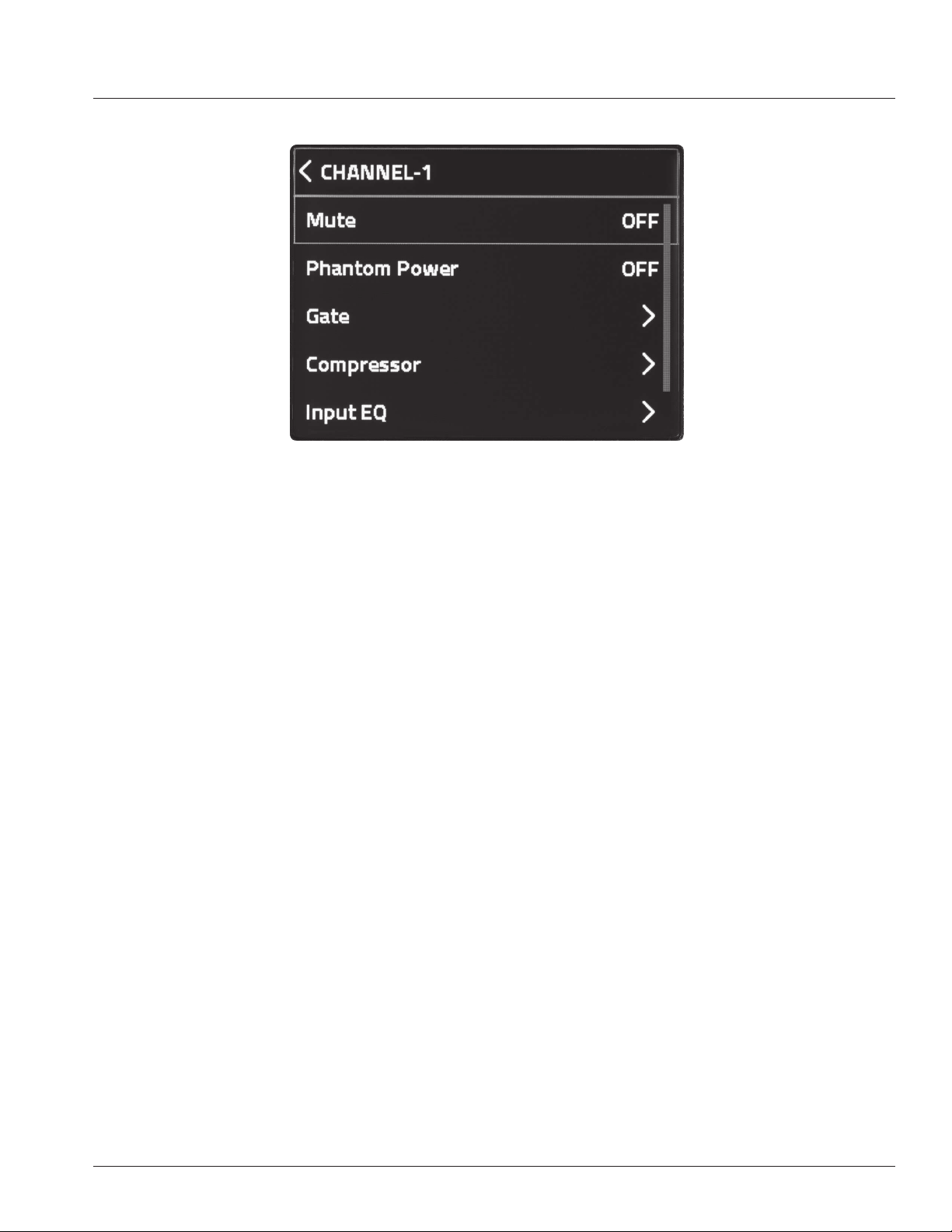
Channel Menu
1. The channel menu can be accessed by pressing the rotary knob of the respective channel you wish to access.
The active channel is visible at the top line of the LCD as well as by the dynamic LED below the respective
channel number.
a. The MUTE eld will mute the respective channel.
i. While in mute, the SSM LED of the muted channel will fade RED.
ii. You can also MUTE a channel by holding the respective channel knob for 2s.
b. Channels 1-2 offers users +48v of Phantom Power. You can engage this in the Channel Menu section.
Please refer to the Phantom Power section of this guide for more information.
c. The PRX ONE offers dbx dynamics processing on each channel, with the exception of channel 7.
i. “Gate” enables editing of the gate feature on the rst six input channels. Gates enable reduction of
the signal below the gate threshold level to reduce the noise oor of the input channel. Examples
include use with multiple open stage mics or when used as inputs from noisy guitar or bass amps.
. To activate the Gate, Press the CH knob to enter channel strip mode and bring up the CHANNEL
MENU.
. To select the GATE, rotate the MASTER/MENU knob to the GATE eld and PRESS the
MASTER/MENU knob.
. “Gate” On/Off. Turns the gate on or off (i.e. off is gate bypass.)
. “Reset” sets all gate settings on this channel to factory default settings.
. “Presets” are available to quickly select typical noise gate situations. These include setting
for full gates, which shut off all signal when below the Gate Threshold setting. Or stepped
gates, which only reduce the volume a xed amount when the input signal falls below the Gate
Threshold setting.
. If the user selects a preset, the lower two settings are automatically loaded with the
chosen presets settings.

28
. If the user selects either of the lower two settings to edit, the preset settings automatically
load the visible settings into the “Custom” preset, so the user can continue editing the
lower two settings.
. “Gate Threshold” enables the user to set the Gate Threshold level to activate when signal on
this channel drops below this Gate Threshold signal level. All signal content below the Gate
Threshold are reduced -100%.
. “Gate Depth” enables the user to set the Gate Depth to only reduce the signal by a limited
amount. Example: When Gate Depth is set to -10bB anytime the channel signal level is below
the Gate Threshold setting level, the signal is reduced by only -10dB. When the input channel
signal is above the Gate Threshold, no Gate adjustment to the audio signal is made.
. Attack
. Hold
. Release
ii. “Compressor” enables editing of the input channel compressor processing. Compressors reduce the
channel signal level above the compressor Threshold setting, by the amount of the Ratio setting.
. To select the COMPRESSOR, rotate the MASTER/MENU knob to the COMPRESSOR eld and
PRESS the MASTER/MENU knob.
. “Compressor” On/Off turns the input channel compressor on or off (i.e. off is compressor in
bypass.)
. “Reset” sets all compressor settings on this channel to factory default.
. “Presets” are available to select for typical creative situations. These Presets have common
compressor settings based on common use cases and can be quickly recalled.
. If the user selects a “Preset”, the lower seven settings are automatically loaded with the
chosen presets settings.
. If the user then selects and edits any of the lower seven settings, the current preset
settings are automatically loaded into the “Custom” preset for further user editing of any
setting.
. “Threshold” sets the signal level where compressor engages. All signal above that Threshold
level will be compressed down by the relative adjustment of the Ratio setting.
. “Ratio” enables the user to set the ratio to percentage the channel audio signal above the
Threshold is reduced when above the Threshold setting.
. OverEasy™ Enabling “OverEasy” smooths the transition before the signal reaches the
Threshold level to provide a more smooth Threshold character transition. OverEasy is often
desired on rock ballads or speaking panels. Disabling “OverEasy is often turned off when mixing
harder rock or DJ style music.
. “Makeup Gain” can be used to raise the compression result peak reduced audio signal, to now
raise the dynamically reduced signal to better t or stand out in a total mix.
. Warning: Using compressor “Makeup Gain” on already loud audio signals may exceed

29
desired channel gain levels. This setting is best used only by skilled audio professionals.
Small movements are often best.
. “Attack” sets the time the compressor takes to start reducing the signal after the Threshold is
exceeded.
. “Hold” sets the time the compressor holds the compressor on after the “Attack” is completed.
. “Release” sets the time the compressor releases the Ratio compression after the audio signal
level falls below the Threshold setting level.
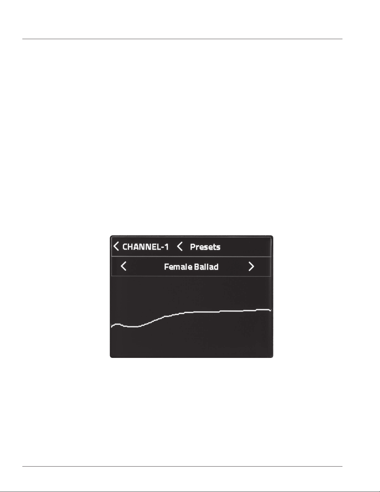
d. The Input EQ section accesses the xed and parametric EQ for each channel. The input channel EQs are
lter adjustments on the audio input channels.
i. Presets include a collection of easy to select preset curves for common creative uses.
ii. Input channel EQ’s include a high pass lter for reducing the combined low-frequency energy build-up
on stage, Bass/Middle/Treble simple controls that can be adjusted on the hardware channel knobs or
LCD screen, and parametric EQ bands with individual gain, frequency, and width (“Q”) for ne lter
editing control.
iii. “Channel #” On/Off enables or bypasses the input channel EQ processor.
iv. “Reset” Selecting the “Reset” sets the input channel EQ to factory default, i.e. at curve.
v. “Presets 8x” opens the user selection of Input EQ presets.
. Users can rotate the Master/Menu knob to see the available input EQ presets.
. Click the Master/Menu knob to load the current showing preset.
. With any input EQ preset showing, users can double click the Master/Menu knob to open the
input EQ editing page.
. Inside the EQ editing page, rotate the Master/Menu knob to select the HPF (high pass lter), the
Bass/Middle/Treble controls, or select any parametric EQ band number and click the knob to
load editing on that band.
. On Parametric EQ bands, rotate and select different settings to edit, including gain (plus or
minus in dB), lter frequency, or “Q” (i.e. adjust the lter width.)
vi. To access the channel EQ settings, rotate the MASTER/MENU knob to the INPUT EQ eld and PRESS
the MASTER/MENU knob.
e. The FX Send section accesses the sends to each respective effect. All FX sends are “post fader level,” so
when a user adjusts the channel fader, the same relative level or mute is reected on the channel FX send.
i. To access, navigate to the FX Send section and Press the MASTER/MENU knob.
ii. Navigate to the effect send you wish to change and press the MASTER/MENU knob.
. A clockwise turn will increase the effect send.
. A counter-clockwise turn will decrease the effect send.
. Press MASTER/MENU to save your edits.
. Press BACK to cancel your edits.

30
Settings
1. “BT Audio Pairing” enables Bluetooth audio pairing for up to 30 seconds. This setting turns off when a pairing
has been made, or after 30 seconds.
2. “BT Control Pairing” enables Bluetooth control pairing for up to 30 seconds with the JBL Pro Connect app. This
turns off when a pairing has been made, or after 30 seconds.
3. When activating BT pairing, a pairing window will pop-up indicating BT Pairing has been initiated. Once
successfully paired, this window will disappear.
4. “LCD Contrast” allows the user to adjust the LCD contrast between 0 and 100%.
5. “Firmware Version” shows the current rmware version loaded onto the speaker.
6. “Factory Reset” resets all settings in the speaker to factory default, including Bluetooth communication pairing.
NOTE:
This will also reset any user-saved presets.

31
JBL Pro Connect
The JBL Pro Connect app is a Bluetooth Low Energy control application used to remotely control the features within the PRX
ONE. The app is a free download on iOS and Android.
It is recommended that all users download the app and ensure their unit is operating on the latest
firmware for the best experience.
APP
32
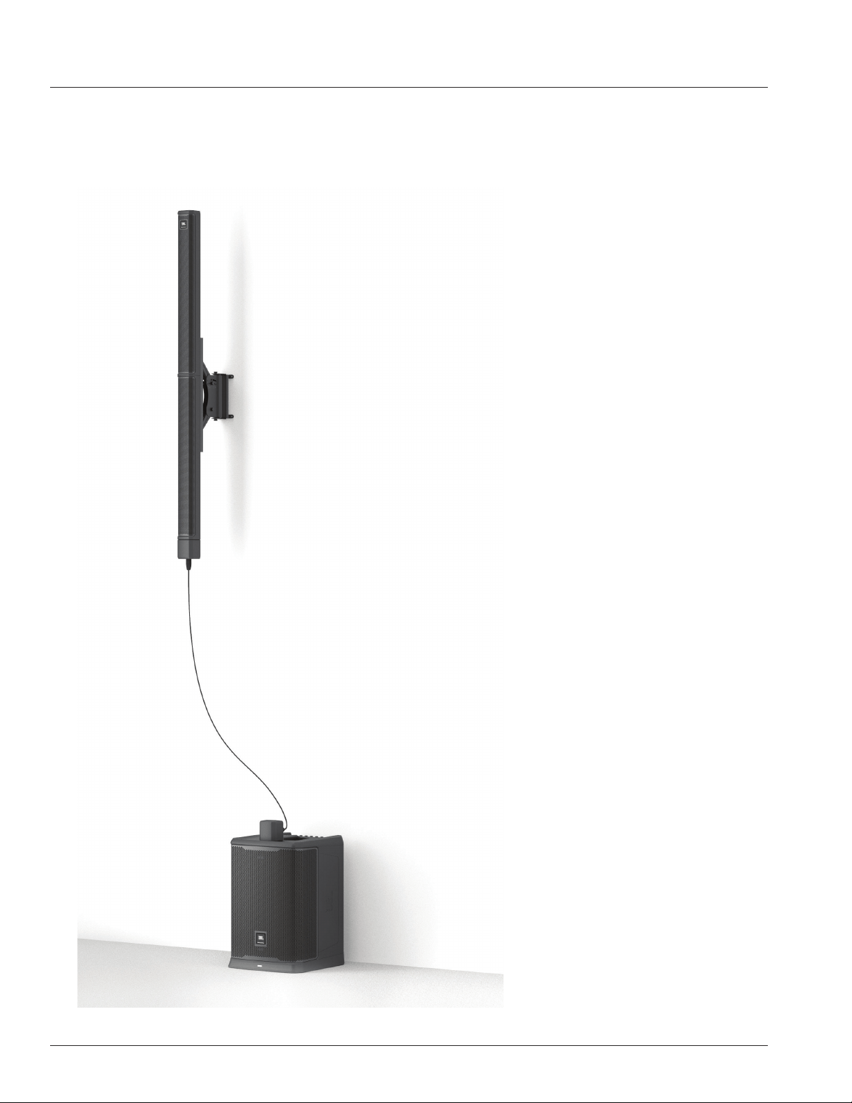
OPTIONAL ACCESSORIES
Wall Mount Bracket Kit
PRX ONE Adapter Bracket Kit can be used to install the unit to a wall mount.

33
PRX ONE SPECIFICATIONS
TECHNICAL SPECIFICATIONS
System Type Powered Column PA Speaker
Woofer Size 12"
Tweeter Size 2.5"
Tweeter Count 12
Max SPL 130dB
Freq Range -10 35-20kHz
Freq Range -3 40-20kHz
Hor Dispersion 130º
Vert Dispersion 30º
Power Rating 2000W Peak
1000W RMS
AC Power Input 300W 100-230V AC 50-60Hz
Input Impedence 4kΩ balanced Combo
2MΩ balanced Hi-Z Jack
10kΩ 3.5mm single ended 2 channel.
Crossover Freq 260Hz
I/O 4 XLR/1/4” Combo Jacks
2 1/4"" Hi-Z
1 1/8""/BT Summed"
1 XLR Pass Through
Cabinet PP
Net Weight 25.7kg
Gross Weight 31.75kg
Shipping DIMs W482mm x D647mm x H850mm
Product dims: 2042mm (H) x 446mm (D) x 375mm (W)
34
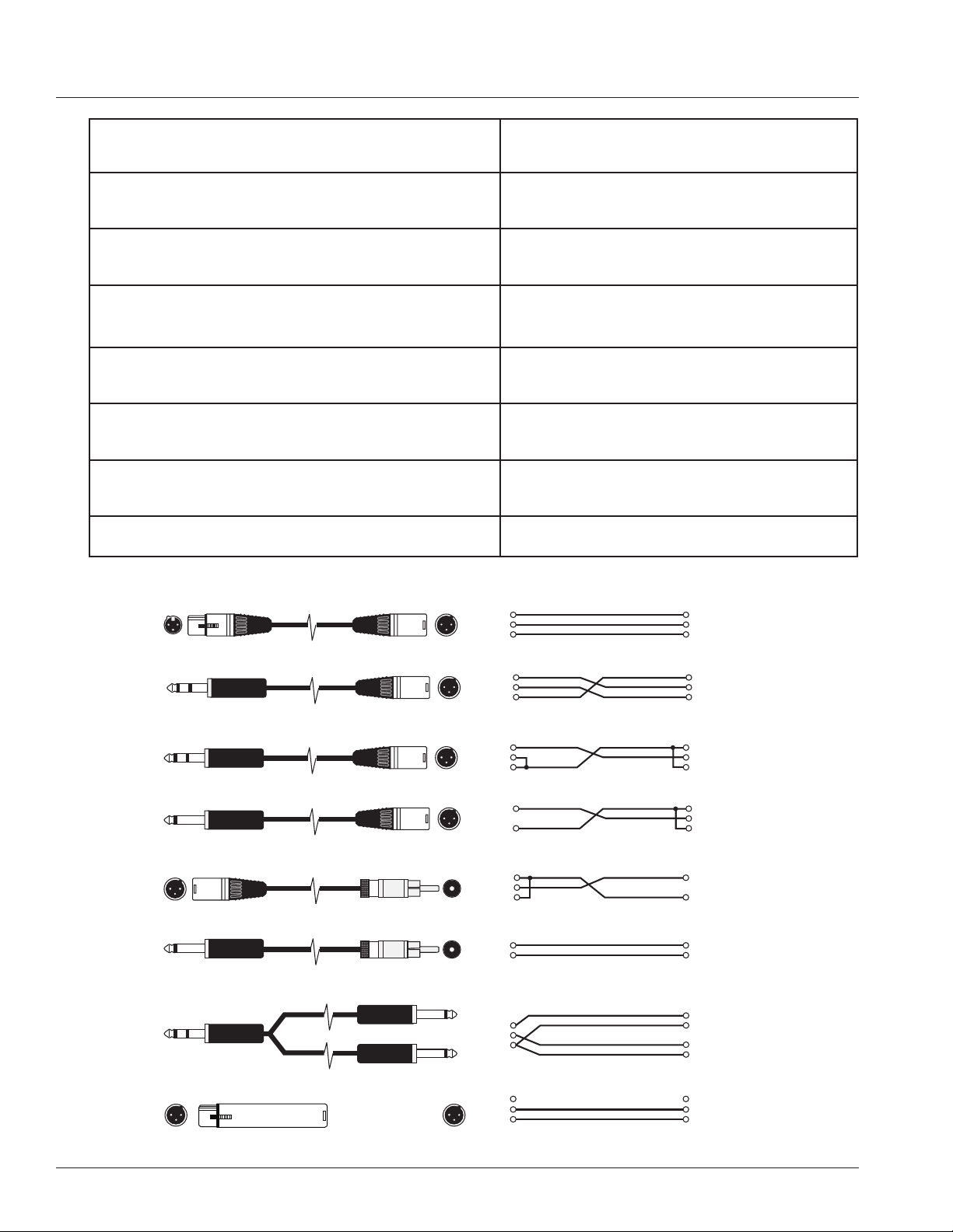
XLR/F to XLR/M Microphone Cable
TRS (Balanced) 1/4" Phone to XLR/M Cable
TRS (Unbalanced) 1/4" Phone to XLR/M Cable
TS (Unbalanced) 1/4" Phone to XLR/M Cable
XLR/M to RCA (Phono) Cable
TS (Unbalanced) 1/4" Phone to RCA (Phono) Cable
TRS 1/4" Phone to dual TS 1/4" Phone Cable
XLR/F to XLR/M Audio Ground Lift Adapter
Tip Ring Sleeve
Tip Ring Sleeve
Tip Sleeve
Tip Sleeve
Tip Ring Sleeve
TipSleeve
TipSleeve
1
2
3
Tip
Ring
Sleeve
Tip
Ring
Sleeve
Tip
Sleeve
1
2
3
Tip
Sleeve
1
2
3
Tip
Ring
Sleeve
1 (no connection)
2
3
Tip
Sleeve (shield)
Tip
Sleeve (shield)
Tip
Sleeve (shield)
Sleeve (shield)
Tip
1 (shield)
2
3
1 (shield)
2
3
1 (shield)
2
3
1 (shield)
2
3
XLR/F to XLR/M Microphone Cable
The standard cable for interconnection of microphone and
line level signal in professional audio systems.
• Microphone to mixer
TRS (balanced) 1/4 inch (6.35mm) phone jack to XLR/M
For connecting balanced devices with 1/4 inch
(6.35mm) phone and maybe used interchangeably.
TRS (unbalanced) 1/4 inch (6.35mm) phone jack to XLR/M
For connections of instruments with unbalanced out-
puts to balanced XLR inputs.
TS (unbalanced) 1/4 inch phone (6.35mm) jack to XLR/M
This cable is electrically identical to "TRS" (unbal-
anced) 1/4 inch (6.35mm) phone and may be used
interchangeably.
XLR/M to RCA (phono) cable
Connects consumer audio products and some DJ mixer
outputs to professional audio equipment inputs
TRS 1/4 inch Phone jack to dual 1/4 inch (6.35mm) Phone jack
Splits a stereo output into separate left/right signals.
TRS 1/4 inch Phone jack to dual 1/4 inch (6.35mm) Phone jack
Change to a TRS mini-phone jack to connect to the output
of a portable. MP3/CD – player and computer sound cards
to a mixer.
XLR/F to XLR/M audio ground lift Only with balanced in - and outputs
CABLES & CONNECTORS

35
CONTACT INFORMATION
Mailing Address:
JBL Professional
8500 Balboa Blvd.
Northridge, CA 91329
Shipping Address:
JBL Professional
8500 Balboa Blvd., Dock 15
Northridge, CA 91329
(Do not return product to this address without rst obtaining prior authorization from JBL)
Customer Service:
Monday through Friday
8:00am -5:00pm
Pacic Coast Time in the U.S.A.
(800) 8JBLPRO (800.852.5776)
www.jblproservice.com
On The World Wide Web:
www.jblpro.com
Professional Contacts, Outside the USA:
Contact the JBL Professional Distributor in your area.
A complete list of JBL Professional international distributors is provided at our U.S.A. website: www.jblpro.com

36
The JBL Limited Warranty on professional loudspeaker products (except for enclosures) remains in effect for ve years from the
date of the rst consumer purchase. JBL ampliers are warranted for three years from the date of original purchase. Enclosures
and all other JBL products are warranted for two years from the date of original purchase.
Who Is Protected By This Warranty?
Your JBL Warranty protects the original owner and all subsequent owners so long as: A.) Your JBL product has been purchased
in the Continental United States, Hawaii or Alaska. (This Warranty does not apply to JBL products purchased elsewhere except
for purchases by military outlets. Other purchasers should contact the local JBL distributor for warranty information.); and B.)
The original dated bill of sale is presented whenever warranty service is required.
What Does The JBL Warranty Cover?
Except as specied below, your JBL Warranty covers all defects in material and workmanship. The following are not covered:
Damage caused by accident, misuse, abuse, product modication or neglect; damage occurring during shipment; damage
resulting from failure to follow instructions contained in your Instruction Manual; damage resulting from the performance of
repairs by someone not authorized by JBL; claims based upon any misrepresentations by the seller; any JBL product on which
the serial number has been defaced, modied or removed.
Who Pays For What?
JBL will pay all labor and material expenses for all repairs covered by this warranty. Please be sure to save the original shipping
cartons because a charge will be made if replacement cartons are requested. Payment of shipping charges is discussed in the
next section of this warranty.
How To Obtain Warranty Performance
If your JBL product ever needs service, write or telephone us at JBL Incorporated (Attn: Customer Service Department), 8500
Balboa Boulevard, PO. Box 2200, Northridge, California 91329 (818/893-8411). We may direct you to an authorized JBL
Service Agency or ask you to send your unit to the factory for repair. Either way, you’ll need to present the original bill of sale to
establish the date of purchase. Please do not ship your JBL product to the factory without prior authorization. If transportation
of your JBL product presents any unusual difculties, please advise us and we may make special arrangements with you.
Otherwise, you are responsible for transporting your product for repair or arranging for its transportation and for payment of any
initial shipping charges. However, we will pay the return shipping charges if repairs are covered by the warranty.
Limitation of Implied Warranties
ALL IMPLIED WARRANTIES, INCLUDING WARRANTIES OF MERCHANTABILITY AND FITNESS FOR PARTICULAR PURPOSE, ARE
LIMITED IN DURATION TO THE LENGTH OF THIS WARRANTY.
EXCLUSION OF CERTAIN DAMAGES
JBL’S LIABILITY IS LIMITED TO THE REPAIR OR REPLACEMENT, AT OUR OPTION, OF ANY DEFECTIVE PRODUCT AND SHALL
NOT INCLUDE INCIDENTAL OR CONSEQUENTIAL DAMAGES OF ANY KIND. SOME STATES DO NOT ALLOW LIMITATIONS ON
HOW LONG AN IMPLIED WARRANTY LASTS AND/OR DO NOT ALLOW THE EXCLUSION OF INCIDENTAL OR CONSEQUENTIAL
DAMAGES, SO THE ABOVE LIMITATIONS AND EXCLUSIONS MAY NOT APPLY TO YOU. THIS WARRANTY GIVES YOU SPECIFIC
LEGAL RIGHTS, AND YOU MAY ALSO HAVE OTHER RIGHTS, WHICH VARY, FROM STATE TO STATE.
JBL Professional
8500 Balboa Blvd. Northridge, CA 91329 USA
WARRANTY INFORMATION

03/21 8500 Balboa Boulevard Northridge, CA 91329 USA www.jblpro.com