Loading ...
Loading ...
Loading ...
page 6
6. Wiring. (cont.)
[PLEASE NOTE: Wall and/or handheld remote
control must be used for fan to operate. If you
do not wish to use the wall control, please proceed
to Section 7 to continue with fan installation.]
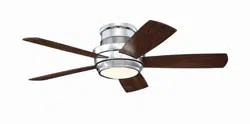
To install wall control, remove existing wall
switch. Wire one of the wall controls with wire
connectors provided as shown in diagram at
right.
*Wrap each wire connector separately with
electrical tape as an extra safety measure.
Gently push wires and taped wire connectors
into outlet box.
Install one 12-volt battery (included) in wall
control.
IMPORTANT: Wall control will not function
unless battery is installed.
Since this fan comes with pre-installed LED
bulbs, the dimmer switch (labeled DIM and
ON) has been pre-set to the "ON" position
(DIM). If you do not wish to have dimming
capability, please move the switch to the
"OFF" position (ON).
Select a faceplate (almond or white) and press
firmly onto front of wall control. Attach wall
control to outlet box and secure with screws
from original wall switch. Attach wall plate
(included) to wall control using 2 screws
provided with the wall control.
(wiring for wall control)
black (OUT to fan)
green
black
(AC IN from
breaker box)
black
(TO POWER supply)
black
green/
green/
bare
bare
ground
ground
green/
bare
ground
outlet box
wall control
face-
plate
12V battery
dimmer
switch
wall plate
11
-
22
-
DIM ON
Modifications not approved by the party responsible for compliance
could void the user's authority to operate the equipment.
*NOTE: This equipment has been tested and found to comply with the limits for a Class B
digital device, pursuant to Part 15 of the FCC Rules. These limits are designed to provide
reasonable protection against harmful interference in a residential installation. This
equipment generates, uses and can radiate radio frequency energy and, if not installed and
used in accordance with the instructions, may cause harmful interference to radio
communications. However, there is no guarantee that interference will not occur in a
particular installation. If this equipment does cause harmful interference to radio or television
reception, which can be determined by turning the equipment off and on, the user is
encouraged to try to correct the interference by one or more of the following measures:
* Reorient or relocate the receiving antenna.
* Increase the separation between the equipment and receiver.
* Connect the equipment into an outlet on a circuit different from that to which the
receiver is connected.
Consult the dealer or an experienced radio/TV technician for help.
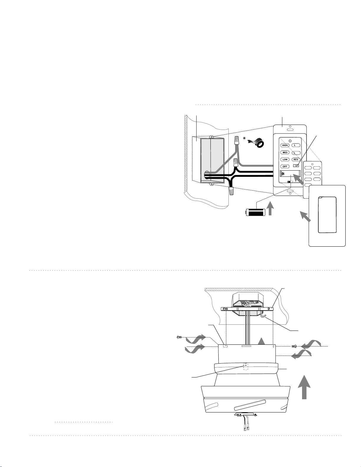
7. Fan Assembly.
Remove motor housing from j-hook on
mounting plate. Lift motor housing to
mounting plate and carefully push wiring
and wire connectors into outlet box.
Align slotted holes on top rim of motor
housing with loosened screws in
mounting plate. Twist motor housing to
lock. Re-insert the 2 screws that were
previously removed (page 4, Section 4)
and then tighten all 4 screws to secure
motor housing.
Locate 4 tabs inside housing ring. Align
tabs in housing ring with 4 screws at top
of motor housing. The tabs must fit
snugly over the screwheads to ensure a
secure fit. NOTE: It is recommended to
push one tab on at a time instead of
doing all four at once.
motor
housing
mounting plate
j-hook
housing ring
tab
slotted hole
Loading ...
Loading ...
Loading ...