1
IMPORTANTSAFETYINFORMATION
PLEASEREADANDFOLLOWTHESEIMPORTANT
INSTRUCTIONSFORTHESAFETYOFYOURHOMEAND
OFTHEPEOPLELIVINGINIT.
SavethisManualforlocalelectricalinspector’suse.
Readandsavetheseinstructionsforfuturereference.
Observeallgoverningcodes,ordinancesandregulations.
‐Donotstoreorusegasolineorotherflammable
substancesinthevicinityofthisoranyotherappliance.
‐WHATTODOIFYOUSMELLGAS
Donotlightanyappliance.
Donottouchanyelectricalswitch.
Donotuseanyphoneinyourbuilding.
Immediatelycallyourgassupplierfromaneighbor’s
phone.Followthegassupplier’sinstructions.
Ifyoucannotreachyourgassuppliers,callthefire
department.
‐Installationandservicemustbeperformedbya
qualifiedinstaller,serviceagencyorthegassupplier
InMassachusetts:Allgasproductsmustbeinstalledbya
"Massachusetts"licensedplumberorgasfitter.A"T"
handletypemanualgasvalvemustbeinstalledinthegas
lineconnectedtothisappliance.
WARNING!
Readthisinstructionbookletbeforeinstallingandusing
theappliance.
Themanufacturerwillnotberesponsibleforany
damagetopropertyortopersonscausedbyincorrect
installationorimproperuseoftheappliance.
Themanufacturerreservestherighttomakechangesto
its products when considered necessary and useful,
without affecting the essential safety and operating
characteristics.
Thisappliancehasbeendesignedfornon‐professional,
domesticuseonly.
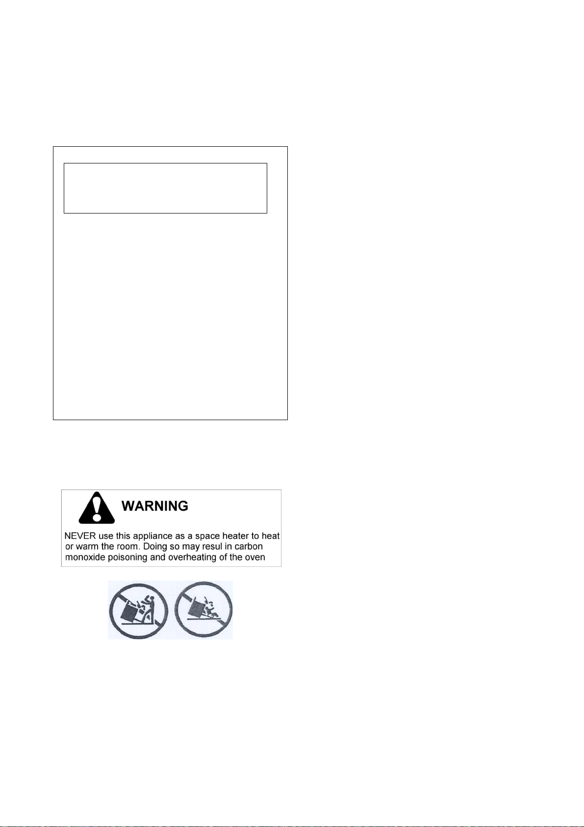
Donotusethisappliancetoheataroom.
Donotplaceanypotorpanontheopenovendoor.The
doorismadeofglassanditcanbreak
ifloadedwitha
weight.
Before beginning installation, please read these
instructionscompletelyandcarefully.
Do not remove permanently affixed labels, warnings, or
plates from the product. This may void the warranty.‐
Please observe all local and national codes and
ordinances.
Pleaseensuretherangeisproperlygrounded.
The installer should
leave these instructions with the
consumerwhoshouldretainforlocalinspector'suseand
forfuturereference.
Theplugshouldalwaysbeaccessible.
Installation must conform with local codes or in the
absence of codes, the National Fuel Gas Code ANSI
Z223.1 / NFPA 54. Electrical installation must be in
accordance with the National Electrical Code,
ANSI/NFPA70‐latest edition and/or local codes. IN
CANADA: Installation must be in accordance with the
current CAN/CGA‐B149.1 National Gas Installation Code
or CAN/CGA‐B 149.2, Propane Installation Code and/or
localcodes. Electrical installationmust bein accordance
with the current CSA C22.1 Canadian Electrical
Codes
Part1and/orlocalcodes.
Installation of any gas‐fired equipment should be made
byalicensedplumber.Amanualgasshut‐offvalvemust
be installed in the gas supply line ahead of the oven in
thegasflowforsafetyandeaseofservice.
WARNING
This appliance
shall not be installed with a ventilation
system that blow air downward toward the
range/rangetop/cooktop;this type of ventilation system
maycauseignitionandcombustionproblemwiththegas
appliance resulting in a personal injury or unintended
operation
WARNING
An air curtain or other overhead
range/rangetop/cooktop hood, which operates by
blowing
a downward airflow onto a
range/rangetop/cooktop, shallnot be used/installed in
conjunctionwiththisgasrange/rangetop/cooktop,
Warning!
This range can tip. Injury to persons could result.
Install anti-tip device shipped with range. See
Installation Instructions.
WARNING!
Iftheinformationinthismanualisnotfollowed
exactly,afireorexplosionmayresultcausing
propertydamage,personalinjuryordeath.
2
BERTAZZONISpA
ViaPalazzina8
42016GuastallaRE
ITALY
WWW.BERTAZZONI.COM
Model
MAS244GASXE[MLS0GNA8X5A]
FromthedeskofthePresident
DearnewownerofaBertazzoniproduct,
Iwanttothankyouforchoosingoneofour
beautifulPROranges.Weknowthatyouhavemany
brandsandproductstochoosefromandweare
thrilledthatyouhavedecidedtotakeoneofour
productsintoyourhome.
Wetake
asmuchprideinmakingourrangesaswe
hopeyouwillinowningthem.Myfamilystarted
manufacturingcookingappliancesin1882.Eachof
ourproductsisablendofItaliandesignfinesseand
superiorappliancetechnolo gy.Whilewecannot
replaceyouruniquetalentatcookingdelicious
recipes
foryourself,yourfamilyandyourfriends,
wetryourbesttomakecookingeasier,more
effectiveandmorefun.
Ourappliancesaredesignedaccordingtothe
strictestsafetyandperformancestandardforthe
EuropeanandtheNorthAmericanmarket.We
followthemostadvancedmanufacturing
philosophy.Eachapplianceleavesthe
factoryafter
thoroughqualityinspectionandtesting.Our
distributorsandourservicepartnersarereadyto
answeranyquestionsyoumayhaveregardinghow
toinstall,useandcareforyourBertazzoniproduct.
Thismanualwillhelpyoulearntousetheproduct
inthesafestandmosteffectivemanner
andcare
foritsothatitmaygiveyouthehighestsatisfaction
foryearstocome.
Themanualalsoincludesdirectionsforthe
professionalinstallerthatwillinstalltheproductin
yourhome.Werecommendusingfactory‐trained
professionalsforthedelicatetaskofinstallingand
testingappliancesinyour
home.Pleasecall
CustomerServiceat(800)ifyouneedhelplocating
afactory‐trainedprofessionalinstallerinyourarea.
Pleasekeepthismanualforfutureuse.
Grazie!

3
TABLEOFCONTENTS
IMPORTANTSAFETYINFORMATION........................................................................................................................1
WARRANTYANDSERVICE..........................................................................ERRORE.ILSEGNALIBRONONÈDEFINITO.
CUSTOMERSERVICE................................................................................................ERRORE.ILSEGNALIBRONONÈDEFINITO.
REPLACEMENTPARTS.............................................................................................ERRORE.ILSEGNALIBRONONÈDEFINITO.
PRODUCTSPECIFICATIONS.......................................................................................................................................5
BEFOREINSTALLATION............................................................................................................................................6
INSTALLINGTHELEGS..............................................................................................................................................7
INSTALLINGTHEWORKTOPFRONTGUARD..............................................................................................................7
INSTALLINGTHEBACKGUARD..................................................................................................................................8
INSTALLINGTHEANTI‐TIPSTABILLTYDEVICE............................................................................................................9
INSTALLATIONREQUIREMENTS...............................................................................................................................9
ELECTRICAL....................................................................................................................................................................9
GAS.................................................................................................................................................................................9
INSTALLATIONADJACENTTOKITCHENCABINETS...................................................................................................10
EXHAUSTHOODINSTALLATION.............................................................................................................................10
ELECTRICALCONNECTION......................................................................................................................................11
GASCONNECTION.................................................................................................................................................12
PRESSUREREGULATOR................................................................................................................................................13
GASCONVERSION............................................................................................................................... ..................14
STEP1:PRESSUREREGULATOR....................................................................................................................................14
STEP2:SURFACEBURNERS..........................................................................................................................................15
STEP3:MAINOVENBURNER.......................................................................................................................................15
STEP4:BROILERBURNER.............................................................................................................................................16
STEP5:VISUALCHECKS................................................................................................................................................16
STEP6:MINIMUMFLAMEADJUSTMENT.....................................................................................................................17
INSTALLATIONCHECKLLST.....................................................................................................................................19
FINALPREPARATION.............................................................................................................................................19
USERMANUAL......................................................................................................................................................20
ROOMVENTILATION.............................................................................................................................................20
SURFACEBURNERLAYOUT....................................................................................................................................20
SURFACECOOKING................................................................................................................................................21
SYMBOLS......................................................................................................................................................................21
SURFACEBURNEROPERATION....................................................................................................................................21
TIPSFORUSINGBURNERSCORRECTLY........................................................................................................................22
TIPSFORUSINGPANSCORRECTLY...............................................................................................................................22
OVENCOOKING.....................................................................................................................................................23
SYMBOLS......................................................................................................................................................................23
OVENSHELVES.............................................................................................................................................................23
GASOVENOPERATION.................................................................................................................................................24
CONVECTIONCOOKING...............................................................................................................................................25
COOKINGWITHTHEGASBROILER...............................................................................................................................25
MAINTAININGYOURRANGE..................................................................................................................................26
CLEANINGYOURRANGE........................................................................................................................................26
IMPORTANTAPPLIANCEINFORMATION................................................................................................................27

4
Please kindly register on our web site www.bertazzoni.com
to validate your new product warranty and help us to
assistyoubetterincaseofanyinconvenience.
TWOYEARLIMITEDWARRANTY
The warranties provided by Bertazzoni Spa in this statement apply exclusively to Bertazzoni appliances and
accessories sold as new products to the original owner by a Bertazzoni authorized distributor, retailer, dealer or
service center and installed in the United States and Canada. The warranties provided in this statement are not
transferable
andhavevalidityfromthedateofinstallation.
COVERAGEINFORMATION
Bertazzoni SpA will repair or replace any component part which fails or proves defective due to materials and/or
workmanship within 2 yearsfrom the dateof installation and underconditions of normal residential use. Repair or
replacementwill be
free of charge,includinglabor at standard ratesand shipping expenses. Repairservice must be
performedbyaBertazzoniAuthorizedServiceCenterduringnormalworkinghours.
COSMETICWARRANTY
Bertazzoniwillcoverpartsshowingcosmeticdefectsinmaterialandworkmanshipforaperiodofthirty(30)daysfrom
date of installation of the unit. This coverage will includescratches, stains, surface imperfections on stainless steel,
paint and porcelain, with the exclusion of slight differences in color due to
materials and painting/enamelling
technologies.
Exclusionsarelaborcosts,Bstockitems,out‐of‐boxappliancesanddisplayunits.
HOWTOOBTAINSERVICE
ToobtainwarrantyservicepleasecontactBertazzoniCustomerServiceatthenumbersbelowandprovidemodel
number,serialnumberanddateofpurchase.
ENGLISH8669050010‐FRANCAIS8005617265
Saveproofoforiginalpurchaseoroforiginalinstallationtoestablishwarrantyperiod.Copyoftheproductserialtagis
affixedtothebackcoveroftheinstructionmanual.
WHATISNOTCOVERED
1 Theproductusedinanycommercialapplication
2 RepairserviceprovidedbyotherthanaBertazzoniauthorizedserviceagency.
3 Damageorrepairservicetocorrectserviceprovidedbyanunauthorizedagencyortheuseofunauthorized
parts.
4 Installationnotinaccordancewithlocal
electricalcodesorplumbingcodes.
5 Defectsordamageduetoimproperstorageoftheproduct.
6 Defectsordamageormissingpartsonproductssoldoutoftheoriginalfactorypackagingorfromdisplays.
7 Servicecallsorrepairstocorrecttheinstallationoftheproductand/orrelatedaccessories.
8
Servicecallstoconnect,convertorotherwiserepairtheelectricalwiringand/orgaslinetoproperlyusethe
product.
9 ServicecallstoprovideinstructionsontheuseofaBertazzoniproduct.
10 Repairserviceduetoproductusageinmannerotherthanwhatisnormalandcustomaryforhome
use.
11 Replacementofwearandtearparts
12 Replacementofglassesandlightbulbsiftheyareclaimedtohavefailedlaterthan30daysafterinstallation
andinnocaselaterthan4monthsafterdateofpurchase
13 Defectsanddamagesarisingfromaccident,alteration,misuse,abuse,improper
installation.
14 Defectsanddamagesarisingfromtransportationoftheproducttothehomeoftheowner.
15 DefectsanddamagearisingfromexternalforcesbeyondthecontrolofBertazzoniSpAsuchasfire,flood,
earthquakesandotheractsofGod.
In case the product will be installed in a remote area, where certified trained technicians are not reasonably
available, the customer will be responsible for the transportation costs for the delivery of the product to the
nearestauthorizedservicecenterorforthedisplacementcostsofacertifiedtrainedtechnician.
Bertazzonidoesnotassumeanyresponsibilityforincidentalorconsequentialdamages.
Somestatesdonotallowtheexclusionorlimitationofincidentalorconsequentialdamages,sotheabovelimitation
or exclusion may not apply to you. This warranty gives you specific legal rights and you may also have other rights
which
mayvaryfromstatetostateorprovincetoprovince.
5
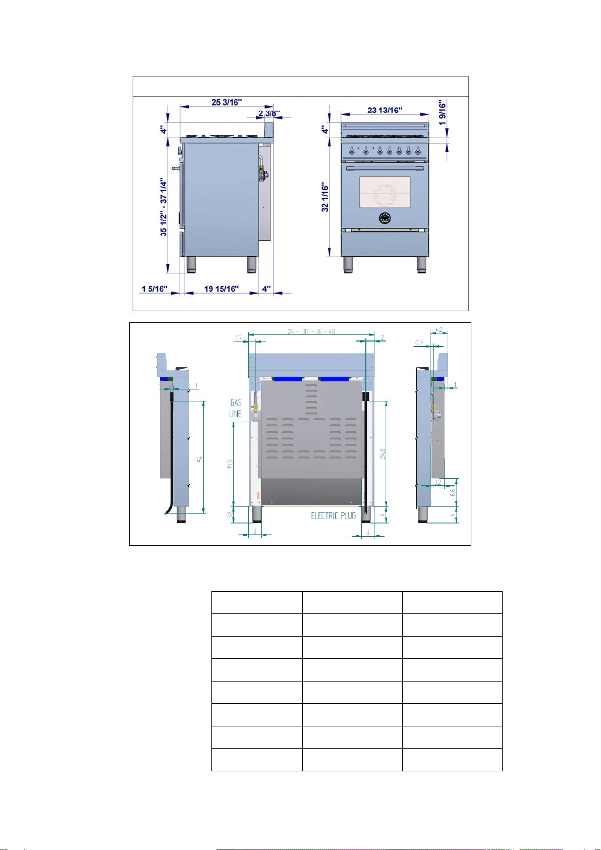
PRODUCTSPECIFICATIONS
Dimensions(insertdrawingsfront,sideandback
Weight
Burnerpower
Naturalgas
LPgas
Auxiliary
3750BTU/h 3750BTU/h
Semi‐rapid
6000BTU/h 6300BTU/h
Rapid
10400BTU/h 11400BTU/h
Dualburner(inner)
2730BTU/h 2900BTU/h
Dualburner(outer)
15000BTU/h 16400BTU/h
Oven 11000BTU/h 11000BTU/h
broiler 10000BTU/h 10000BTU/h

6
BEFOREINSTALLATION
This appliance shall only be installed by an
authorizedprofessional.
This appliance shall be installed in accordance
withthemanufacturer’sinstallationinstructions.
This appliance must be installed in accordance
withthenorms&standards ofthecou ntrywhere
it will be installed. The installation of this
appliance must conform to local
codes and
ordinances. In the absence of local codes,
InstallationsmustconformstoAmericanNational
Standards,NationalFuelGasCode ANSI Z223.1/
NFPA54orB149.1.
The appliance, when installed, must be
electrically grounded in accordance with local
codes or, in the absence of local codes, withthe
National
ElectricalCode,ANSI/NFPA70.
If local codes permit, a flexible metal appliance
connection with the new AGA or CGA certified
design, max. 5 feet (1,5 m) long, ½” I.D. is
recommended for connecting this appliance to
the gas supply line. Do not bend or damage the
flexibleconnectorwhenmovingthe
appliance.
This appliance must be used with the pressure
regulator provided. The regulator shall be
properlyinstalledin order tobe accessible when
theappliance isinstalledinitsfinal location.The
pressureregulatormustbesetforthetypeofgas
tobeused.Thepressureregulatorhas½”
female
pipe thread. The appropriate fitting must be
determined based onthe size of your gas supply
line,theflexiblemetalconnectorandtheshutoff
valve.
The appliance must be isolated from the gas
supply piping system by closing its individual
manualshutoffvalveduringanypressuretesting
ofthegas
supplypipingsystemattestpressures
equaltoorlessthan½psi(3.5kPa).
All opening andholes in the wall and floor, back
and under the appliance shall be sealed before
installationoftheappliance.
Amanual valveshallbeinstalledinan accessible
location in the gas
line external to the appliance
for the purpose of turning on or shutting offgas
totheappliance
WARNING!
Donotuseaerosolspraysinthevicinityofthis
appliancewhileitisinoperation
ROOM VENTILATION: An exhaust fan may be
used with the appliance; in each case it
shall be
installed in conformity with the appropriate
national and local standards. Exhaust hood
operationmayaffect othervented appliances; in
each case it shall be installed in conformity with
theappropriatenationalandlocalstandards.
TYPEOFGAS
Thisapplianceisshippedfromthefactoryforuse
with natural
gas. For use with propane lp gas
please follow the conversion procedure
described on pg. 14. A step by step conversion
procedureisalso includedwitheachsetoflpgas
nozzles.
GASPRESSURE
Themaximuminletgassupplypressureincoming
to the gas appliance pressure regulator is ½ psi
(13,8w.c.or3.5kPa).
The minimum gas supply pressure for checking
theregulatorsettingshallbeatleast1“w.c.(249
Pa)abovetheinletspecifiedmanifoldpressureto
the appliance (this operating pressure is 4” w.c.
(1.00kPa)forNaturalGasand11”w.c.(2.75kPa
forLPGas).
7
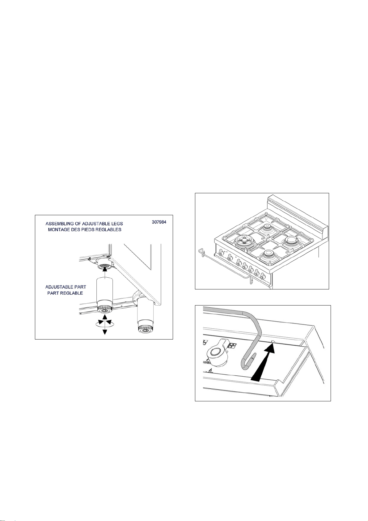
INSTALLINGTHELEGS
Bertazzonirangesmustbeusedonlywiththe
legsproperlyinstalled.
Fourheight‐adjustablelegsareshippedwiththe
rangeinthepolysterenecontainersituatedover
theappliance.
Before installing the legs, position the appliance
nearits finallocationas thelegs arenotsuitable
formovingtheapplianceoverlong
distances.
After unpacking the range, raise it enough to
insert the legs in the appropriate receptacles
situated on the lower part of the appliance.
Lowertherangegentlytokeepany unduestrain
fromlegsandmountinghardware.Ifpossibleuse
apalletorliftjackinsteadoftiltingthe
unit.
Adjust leg height to the desired level by twisting
the inside portion of the leg assembly until the
properheightisreached. Check withalevel that
thecooktopisperfectlylevel.
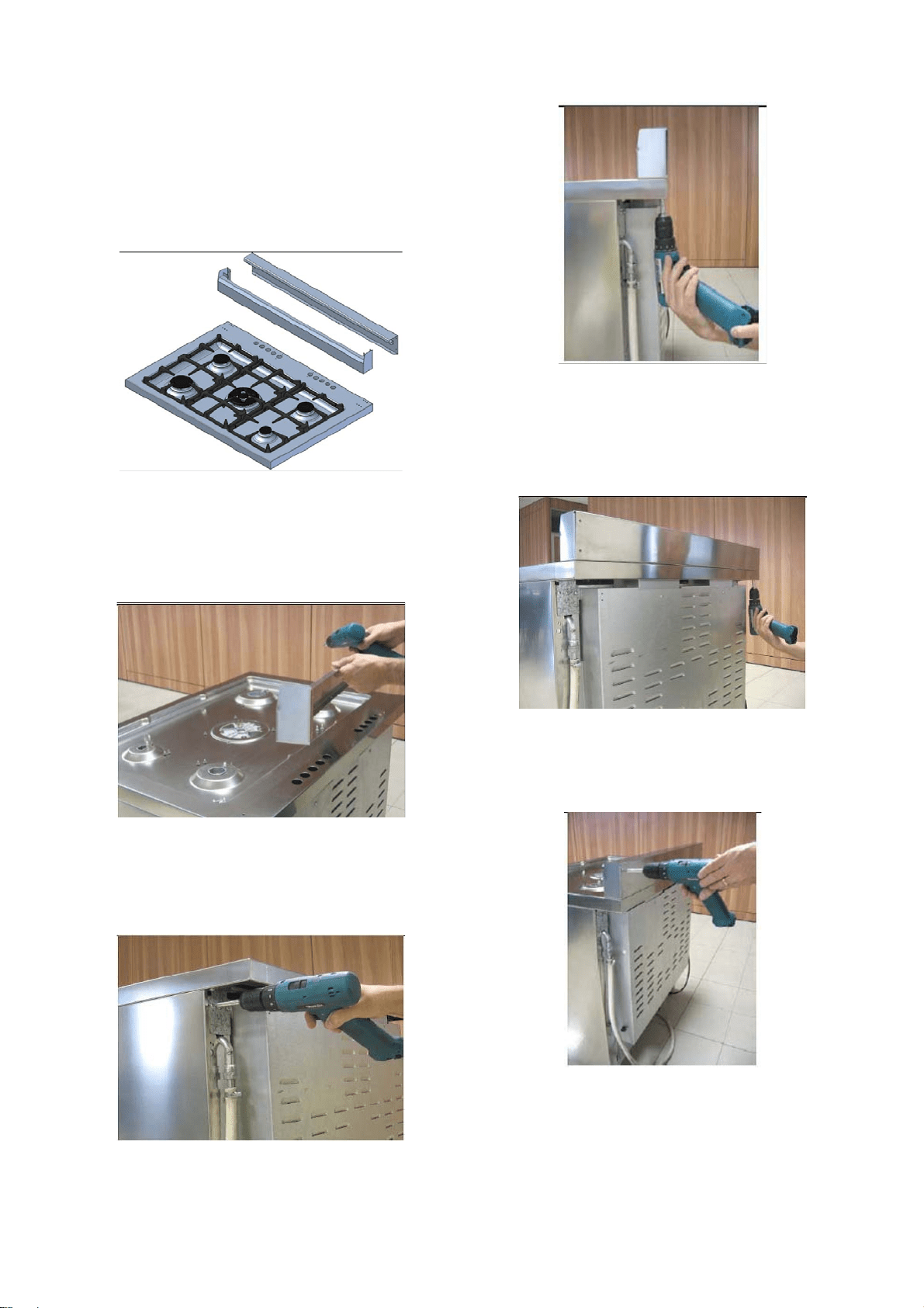
INSTALLINGTHEWORKTOP
FRONTGUARD
Toincreasetheclearancebetweenthefrontedge
of the worktop and the burners it is possible to
install the worktop frontguard shipped with the
appliance.
Toinstallthefrontguard,holditwiththepointed
edges looking up. Align the edges of the
frontguard with the appropriate receptacles in
the
bottom oftheworktopandpressfirmlyuntil
the frontguard is securely attached to the
worktop.
ATTENTION: once installed the frontguard may
only be removed by disassembling the worktop.
Attempting to remove the frontguard without
disassembling the worktop will result in
permanentdamagetotheworktop.
8
INSTALLINGTHEBACKGUARD
The backguard must be installed prior to
operation of the appliance for appropriate
ventilationoftheovencompartment.
Thesuppliedbackguardisa2‐partassembly.The
box also contains a set of metal screws for
securingthebackguardtotheworktop.
Disassemblethebackguardandpositionthefront
part on the worktop. Align the screw holes with
the corresponding holes at the back of the
worktop.
If the holes are not aligned, partially loosen the
brackets att the back of the worktop as shown
below.
Installthefrontpartofthebackguardby
tighteningthe2centralscrewsfromthetopand
2lateralscrewsfromthebottom.
Positionthebackpartofthebackguardand
secureittotheworktoptightening4screwsfrom
thebottom.
Connectthebackandfrontpartoftheupstand.
Checkfortightassembly.
9
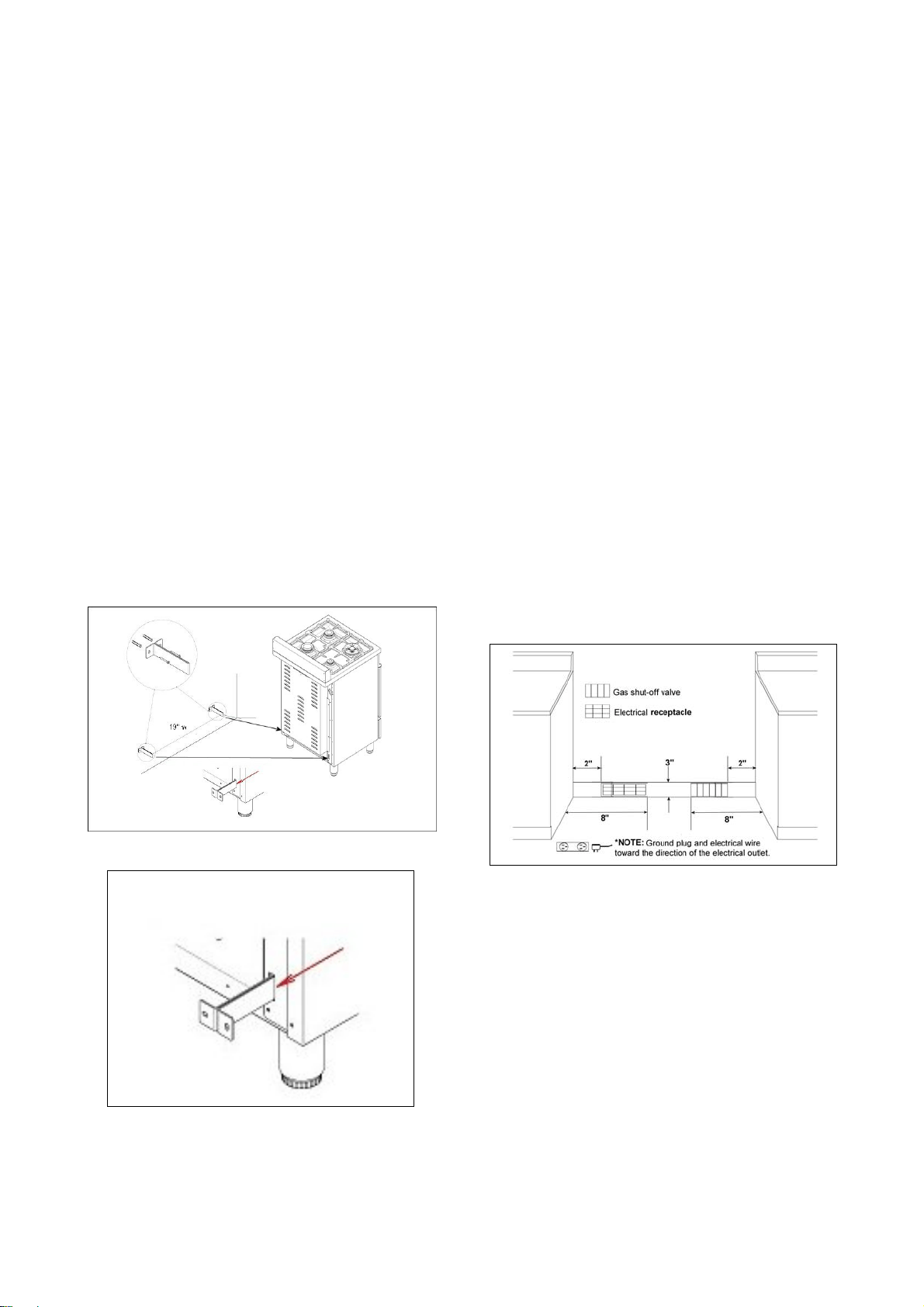
INSTALLINGTHEANTI‐TIPSTABILlTY
DEVICE
Theanti‐tipbracketshippedwiththerangemust
beproperlysecuredtotherearwallasshownin
thepircturebelow.
Theheightofthebracketfromthefloormustbe
determinedaftertherangelegshavebeen
adjustedtothedesiredheightandafterthe
rangehasbeenleveled.
Measurethedistancefromthefloortothe
bottomoftheanti‐tipbracketreceptacleonthe
backoftheappliance.
Positionthetwoanti‐tipbracketsonthewallat
thedesiredheightplus1/8"(0.32cm).The
bracketsmustbeplacedat2”5/16(6,0cm)from
theside
oftherange.Thedistancebetweenthe
twobracketis19”1/4(48,9cm).
Securethebracketstothewallwithappropriate
hardware.
Slidetherangeagainstthewalluntilthebrackets
arefullyinsertedintotheirreceptaclesonthe
backoftherange.
INSTALLATIONREQUIREMENTS
ELECTRICAL
Aproperly‐groundedhorizontally‐mounted
electricalreceptacleshouldbeinstallednohigher
than3"(7.6cm)abovethefloor,nolessthan2”
(5cm)andnomorethan8”(20,3cm)fromthe
leftside(facingproduct).
Checkalllocalcoderequirements.
GAS
Anagency‐approved,properly‐sized
manualshut‐
offvalveshouldbeinstallednohigherthan3"
(7.6cm)abovethefloorandnolessthan2”(5
cm)andnomorethan8” (20.3cm)fromtheright
side(facingproduct).
Toconnectgasbetweenshut‐offvalveand
regulator,useagency‐approved,properlysized
flexible
orrigidpipe.Checkalllocalcode
requirements.
10
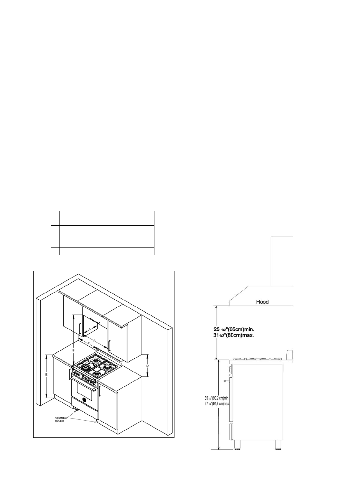
INSTALLATIONADJACENTTOKITCHEN
CABINETS
Thisrangemaybeinstalleddirectlyadjacentto
existingcountertophighcabinets(36"or91.5cm
fromthefloor).
Forthebestlook,theworktopshouldbelevel
withthecabinetcoun tertop.Thiscanbe
accomplishedbyraisingtheunitusingthe
adjustmentspindlesonthelegs.
ATTENTION:therangeCANNOT
beinstalled
directlyadjacenttokitchenwalls,tallcabinets,
tallappliances,orotherverticalsurfacesabove
36"(91.4cm)high.Theminimumsideclearance
insuchcasesis6"(15.2cm).
Wallcabinetswithminimumsideclearancemust
beinstalled18"(45.7cm)abovethecountertop
withcountertopheightbetween
35½”(90.2cm)
and37¼”(94.6cm).Themaximumdepthofwall
cabinetsabovetherangeshallbe13"(33.0cm)
EXHAUSTHOODINSTALLATION
ThisrangewillbestperformwhenusedwithPRO
lineBertazzoniexhausthoods.Thesehoodshave
been designed to work in conjunction with the
Bertazzoni range and have the same finish for a
perfectlook.
For maximum performance, the height of the
bottomof thehood fromthe worktopshould be
between 25 1/2" (65 cm) and 31 1/2" (80 cm).
This would typically result in the bottom of the
hoodbeing 61 1/2"(156.2 cm)to67 1/2"(171.5
cm) above the floor. These measurements
provide for safe and efficient operation of the
hood.
Before installation of the exhaust hood,
consult
local or regional building and installation codes
foradditionalspecificclearancerequirements.
Refer to the range hood installation instructions
provided by the manufacturer for additional
information.
A 24” (61 cm)
B 36” (91,5 cm)
C 13” (33,0 cm)
D 18” (45,7 cm)
E 35”1/2(90,2 cm) / 37” ¼ (94,6 cm)
F 6” (15,2 cm)
11
ELECTRICALCONNECTION
This unit is manufactured for a polarized,
grounded120volt/60Hz,16ampsystem.
Electricpowerconsumption is about300W.
The minimum of 102 VAC is required for proper
operationofgasignitionsystems.
The circuit must be grounded and properly
polarized.
The unit is equipped witth a SJT power
cord. In
case of replacement, the power cord shall be
replaced with one of the same type, size and
length.
ELECTRICALGROUNDING
Thisapplianceisequippedwithathree‐prong
plugforyourprotectionagainstshockhazardand
shouldbepluggeddirectlyintoaproperly
groundedsocket.Donotcut
orremovethe
groundingprongfromthisplug.
WARNING!
ELECTRICALSHOCKHAZARD
Disconnectelectricalpowe ratthecircuit
breakerboxorfuseboxbeforeinstallingthe
appliance.
Provideappropriategroundfortheappliance.
Usecopperconductorsonly.
Failuretofollowtheseinstructionscouldresult
inseriousinjuryordeath
CAUTION
Labelallwirespriortodisconnectingwhen
servicingcontrols.Wiringerrorscancause
improperanddangerousoperation.
Verifyproperoperationafterservicing.
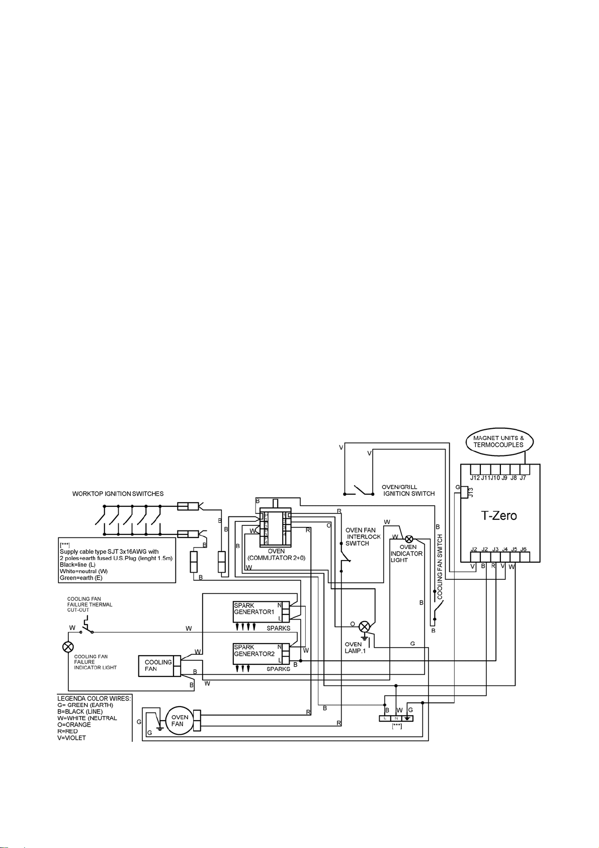
WIRINGDIAGRAM
12
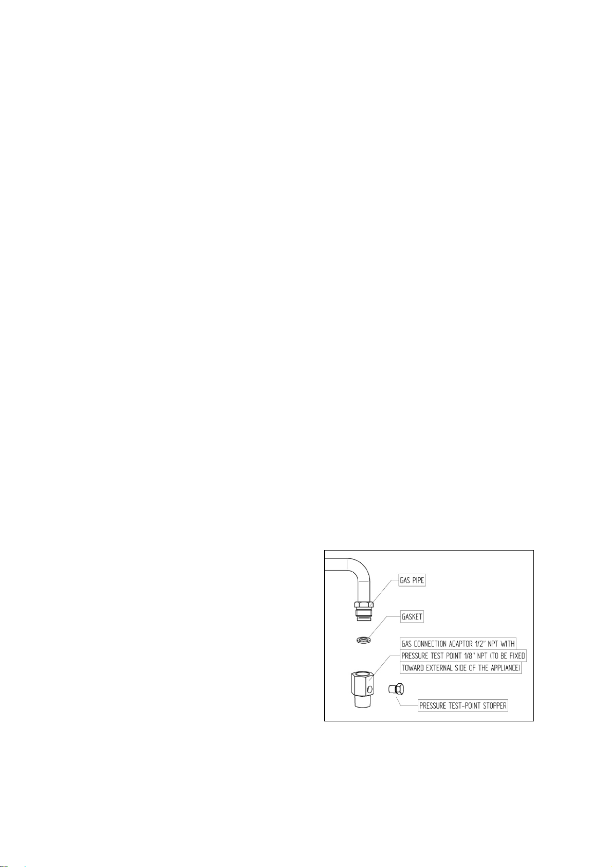
GASCONNECTION
Allgasconnectionsmustcomplywithnational
andlocalcodes.Thegassupplyline(service)
mustbethesamesizeorgreaterthantheinlet
lineoftheappliance.Thisrangeusesa1/2"NPT
inlet(seedrawingbelowfordetailsofgas
connection).Onallpipejointsuseappropriate
sealant
resistanttogas.
Thisrangecanbeused withNaturalor
LP/Propanegas.Therangeisshippedfromthe
factoryforusewithnaturalgas.
ForLP/propanehouseholdinstallation,the
appliancemustbeconvertedbythedealer,bya
factory‐trainedprofessionalorbyaqualified
licensedplumberorgas
servicecompany.
Gasconversionisimportantforsafeandeffective
useoftheappliance.Itistheresponsibilityofthe
dealerandtheowneroftherangetoperformthe
appropriategasconversionfollowingthe
directionsofthemanufacturer.
THEGASCONVERSIONPROCEDUREISDESCRIBED
INTHISMANUALANDINTHE
PACKAGE
CONTAININGTHECONVERSIONNOZZLES
SHIPPEDWITHEVERYRANGE.
Pleaseprovidetheservicepersonwiththis
manualbeforeworkisstartedontherange.
WARNING!
DONOTUSEANOPENFLAMEWHENCHECKING
FORLEAKS!
Leaktestingoftheapplianceshallbeconducted
accordingtothemanufacturer'sinstructions.
Beforeplacing
theovenintooperation,always
checkforleakswithsoapywatersolutionor
otheracceptablemethod.
Checkforgasleakagewithsoapywatersolution
orotheracceptablemethodsinallgas
connectionsinstalledbetweeninletgaspipeof
theappliance,gasregulator,tilltothemanual
shut‐offvalve.
MANUAL
SHUT‐OFFVALVE
THISVALVEISNOTSHIPPEDWITHTHEAPPLIANC
ANDMUSTBESUPPLIEDBYTHEINSTALLER.
Themanualshut‐offvalvemustbeinstalledin
thegasservicelinebetweenthegashook‐upon
thewallandtheapplianceinlet,inaposition
whereitcanbe
reachedquicklyintheeventofan
emergency.
InMassachusetts:A'T'handletypemanualgas
valvemustbeinstalledinthegassupplylineto
thisappliance.
FLEXIBLECONNECTIONS
In case of installation with fle xible couplings
and/or quick‐disconnect fittings, the installer
must use a heavy‐duty, AGA design‐
certified
commercial flexible connector of at least 1/2"
(1.3 cm) ID NPT (with suitable strain reliefs) in
compliance with ANSI Z21.41 and Z21.69
standards.
In Massachusetts: The unit must be installed
witha36"(3‐foot)longflexiblegasconnector.
InCanada:useCAN1‐6.10‐88metalconnectors
forgas
appliancesandCAN1‐6.9M79quick
disconnectdeviceforusewithgasfuel.
PRESSURETEST‐POINTSTOPPERVALVE
To avoid gas leaks, the pressure test‐point
stoppervalveandgasketsuppliedwiththerange
mustbeinstalledonthegasfittingatthebackof
therangeaccordingto
thediagrambelow.
13
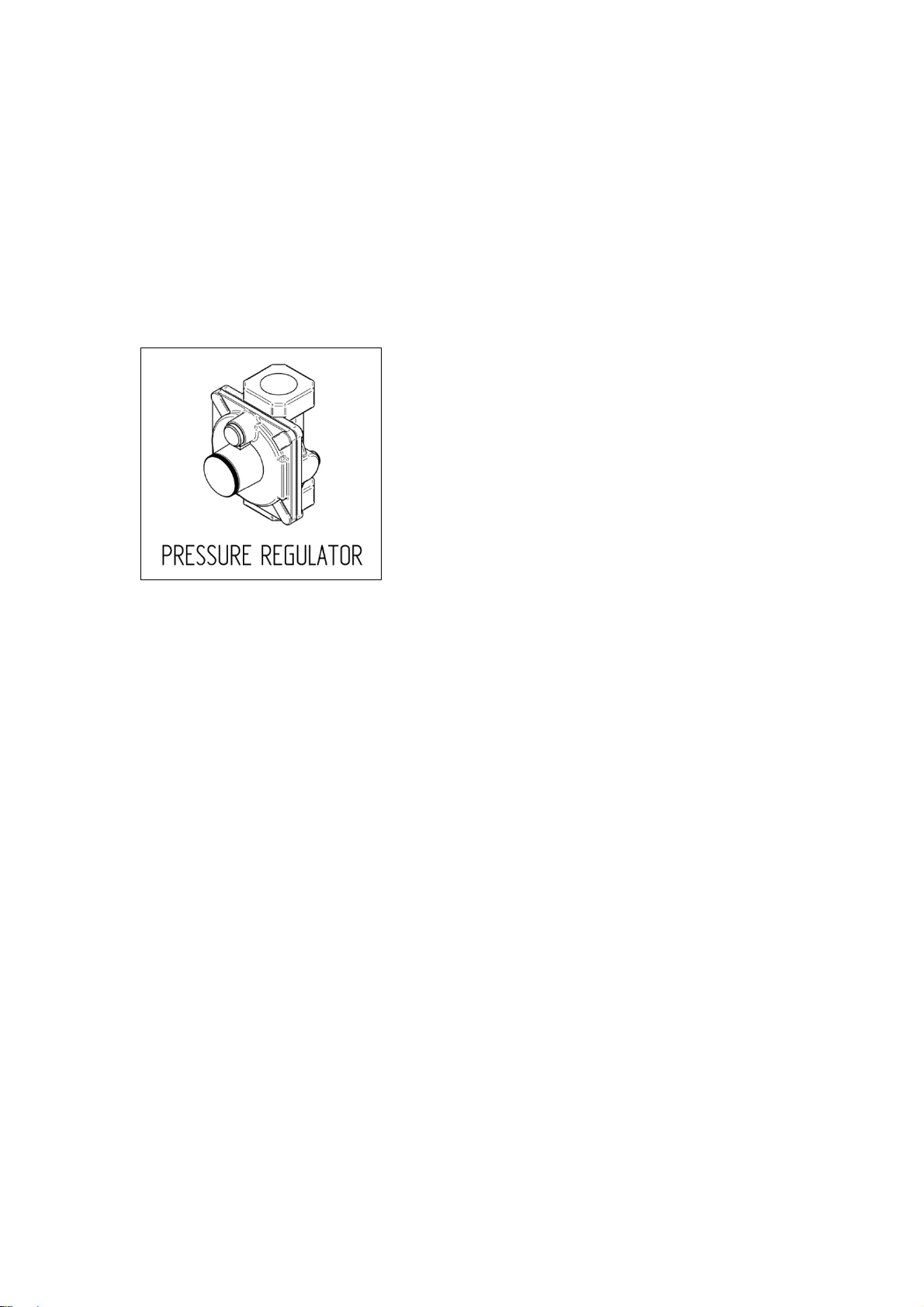
PRESSUREREGULATOR
Since service pressure may fluctuate with local
demand, every gas cooking appliance must be
equipped with a pressure regulator on the
incoming service line for safe and efficient
operation.
The pressure regulator shipped with the
appliance has has two female threads ½” NPT.
The regulator shall be installed
properly in order
tobeaccessiblewhentheapplianceisinstalledin
itsfinalposition.
Manifoldpressureshouldbecheckedwitha
manometerandcomplywiththevaluesindicated
below:
Naturalgas4.0"W.c.P.
LP/Propane11.0"W.C.P.
Incominglinepressureupstreamfromthe
regulatormustbe1"W.c.P.higherthanthe
manifoldpressureinordertocheckthe
regulator.
Theregulatorusedon
thisrangecanwithstanda
maximuminputpressureof1/2PSI(13,8"w.c.or
3,5kPa)Ifthelinepressureexceedsthatamount,
astepdownregulatorisrequired.
The appliance, its individual shut‐off valve, and
the pressure regulator must be disconnected
from the gas line during any pressure testing of
that system at pressures in excess of 1/2 PSI
(13,8"w.c.or3,5kPa).
The individuaL manual shut‐off valve must be in
the OFF position during any pressure testing of
the gas supply piping system at test pressures
equal to or less than 1/2 PSI (13,8" w.c. or 3,5
kPa).
14
APPLIANCESERVICING
Before carrying any servicing operation
disconnect the appliance from gas and electric
supplyandextraappliancefromfinalinstallation
placeinordertohaveaccesstotheappliancefor
properservicingintervention.
GASCONVERSION
WARNING!
Beforecarryingoutthisoperation,disconnect
theappliancefromgasandelectricity.
Gasconversionshallbeconductedbyafactory‐
trainedprofessional.
Callthecustomerservicehotlinetoidentifya
factory‐trainedprofessionalnearyourhome.
The gas conversion procedure for this range
includes6steps:
1. Pressureregulator
2. Surfaceburners
3. Mainovenburner
4. Broilerburner
5. Visualcheckspriortoclosureofovenbottom
panel
6. Adjustmentofminimu msetting
The conversion is not completed if all 6 steps
havenotbeenconcludedproperly.
Beforeperformingthegas conversion,locatethe
package containing the replacement nozzle
shipped with every range. IMPORTANT: Each
nozzle has a number indicating itsflow diameter
printedonthebody.Consultthetableonpage20
formatchingnozzlestoburners.
Save the nozzles removed from the range for
futureuse.
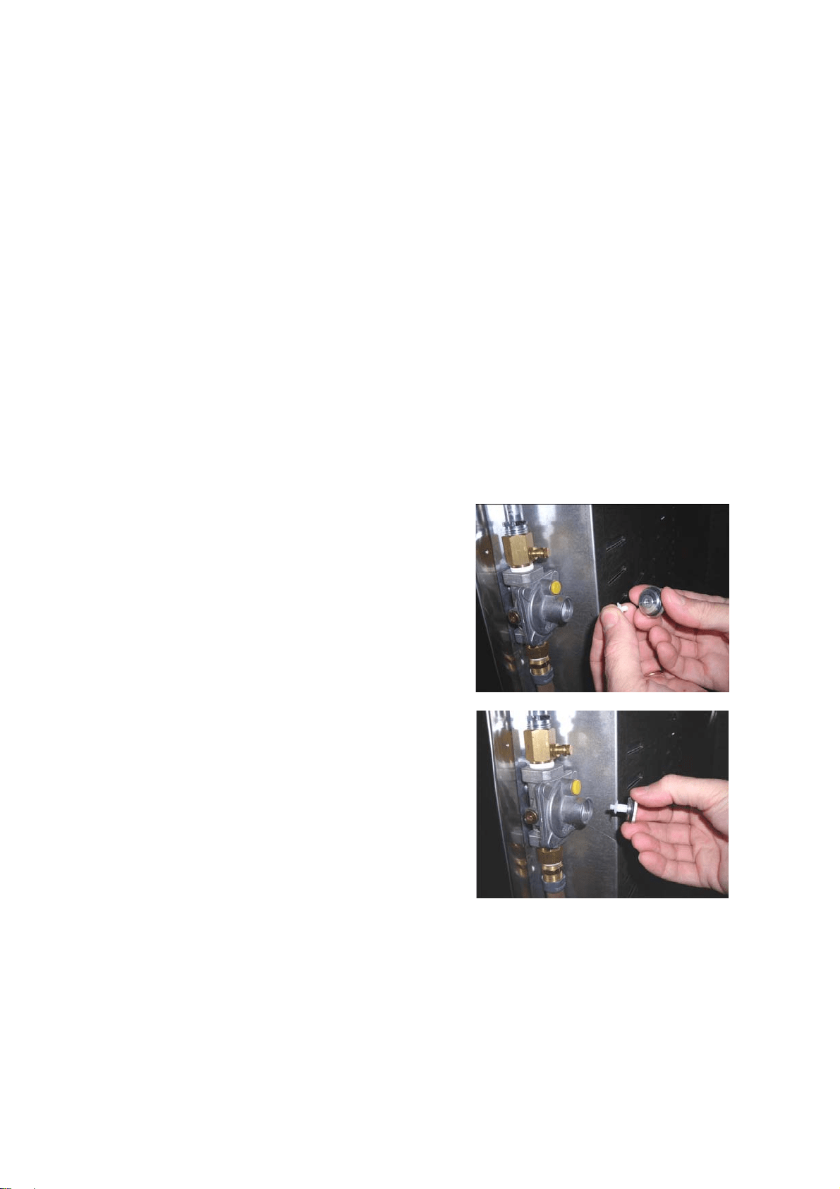
STEP1:PRESSUREREGULATOR
The pressure regulator supplied with the
applianceisaconvertibletypepressureregulator
for use with Natural Gas at a nominal outlet
pressureof4” w.c. or LP gas ata nominal outlet
pressure of 11” w.c. and it is pre‐arranged from
the factory to operate with one of these
gas/pressureas indicatedinthelabels
affixed on
theappliance,packageandInstructionbooklet.
Toconverttheregulatorforusewithotherliquid
propaneLPgas:
1. Unscrew by hand the upper cap of the
regulator, remove the white plastic
attachment from the cap, reverse its
directionand screwitagainfirmlyagainstthe
cap.The
whiteplasticattachmenthasarrows
indicating the position for natural gas (NAT)
andLPgas(LP).
2. Screw by hand the metal cap in the original
positionontheregulator.
15
STEP2:SURFACEBURNERS
Toreplacethenozzlesofthesurfaceburners,lift
up the burnersandunscrew the nozzles shipped
withtherangeusinga7mm{sochetwrench).
Replacenozzlesusingtheconversionsetsupplied
with the range or by a Bertazzoni authorized
parts warehouse. Each nozzle has a
number
indicating itsflowdiameter printed on the body.
Consultthetableonpage20formatchingnozzles
toburners.
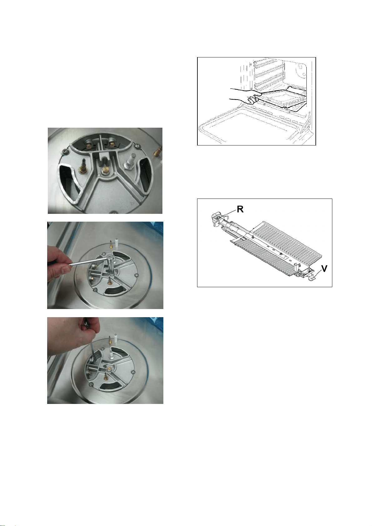
STEP3:MAINOVENBURNER
Toreplacethenozzles ofthemainovenburner,
startby:
Removetheenamelledcavitybaseplate
Loosen and the screw V and pull out the burner
fromthesupportbeingcarefulnottodamagethe
ignitionplugandthethermocouple
UnscrewthenozzleRusinga7mm.spannerand
replaceitwiththenozzleforthenewtypeofgas
accordingtowhatisindicateinthetablebelow
ATTENTION:payextraattentiontoavoiddamage
totheigniterandthermocouple.
Re‐installallthepartsinreverssequence
16
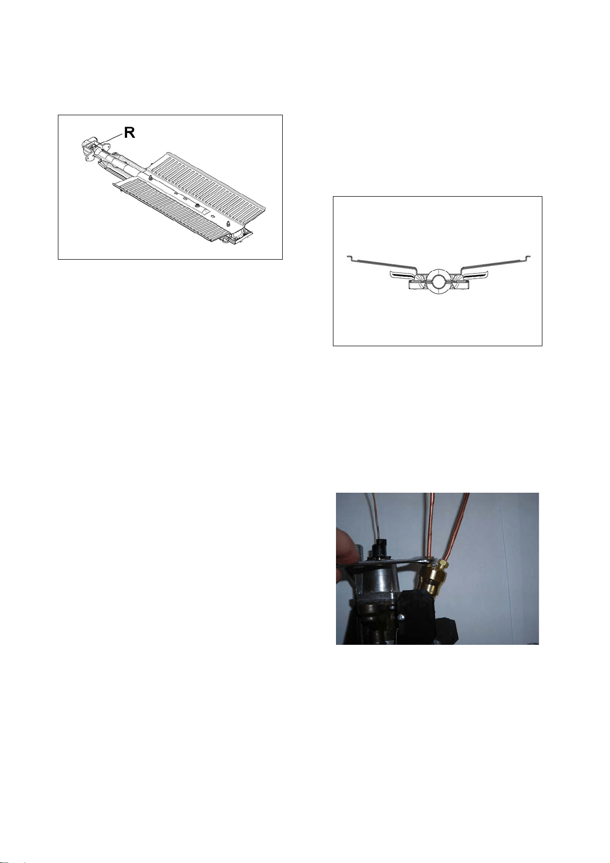
STEP4:BROILERBURNER
Loosen the screw and pull out the burner from
the support being careful not to damage the
ignitionplugandthethermocouple.
Using a 7 mm [name of the tool] unscrew the
nozzle. Replace the nozzl e using the conversion
set supplied with the range or by a Bertazzoni
authorized parts warehouse. Each nozzle has a
number indicating its flow diameter printed on
the body. Consult the table on page 20 for
matching
nozzlestoburners.
STEP5:VISUALCHECKS
Beforereinstallingthebottompanel,the
followingvisualcheckmustbeperformedto
ensurethattheconversionhasbeencarriedout
properlyandwithoutdamagetoother
componentsoftherange.
Verify that the flame of the oven/broiler burner
be completely blue and with
regular aspect as
shownbelow.
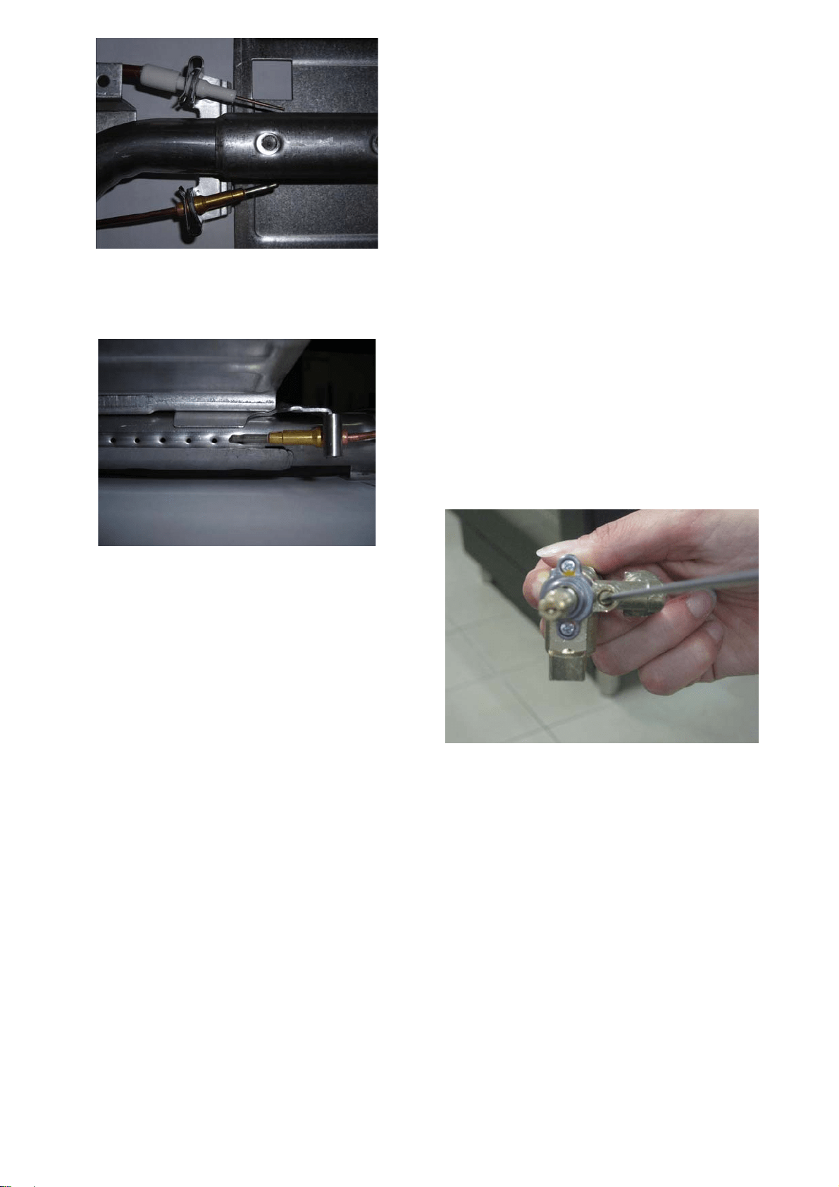
A) CONNECTIONOFTHERMOCOUPLESTO
THERMOSTAT
Thethermocouplesforbothbroilerandmain
ovenburnerareconnectedtothesamemagnet.
Tightgentlythetwoconnectionsalternating
actiononthetwonuts.Donotfullytightenone
thermocouplebeforehavingstartedtotighten
thesecondone.
B) OVENIGNITERANDTHERMOCOUPLE
POSITION
Theappropriategapbetweenthetipofthespark
plugorthermocoupleandtheburnershallbe
approximately1/8’’.
17
Thetipofthesparkplugorthermocouplemust
fullyoverlapatleastthefirstgasemissionholeof
theburner.
Afterperformingallthesevisualchecks,reinstall
thebottompaneloftheovencompartmentand
proceedtosettingtheminimumforeach
burner.
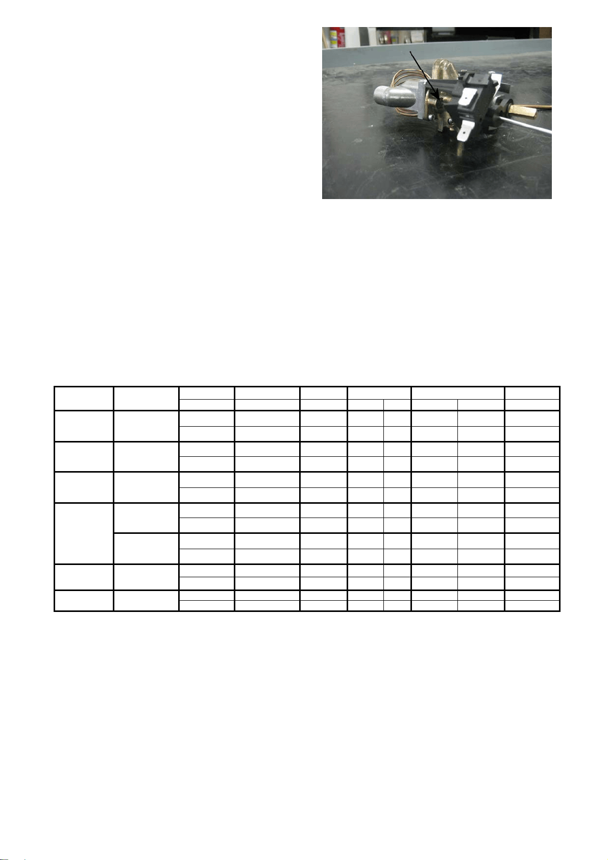
STEP6:MINIMUMFLAMEADJUSTMENT
WARNING!
Theseadjustmentsshouldbemadeonlyforuse
oftheappliancewithnaturalgas.Forusewith
liquid
propanegas,thechokescrewmustbe
fullyturnedinaclockwisedirection.
SURFACEBURNERS
1. Light one burner at a time and set the knob
totheMINIMUMposition(smallflame).
2. Removetheknob.
3. The range is equipped with a safety valve.
Using a small‐size slotted
screwdriver, locate
the choke valve on the valve body and turn
the choke screw to the right or left until the
burnerflameisadjustedtodesiredminimum.
4. Make sure that the flame does not go out
when switching quickly from the MAXIMUM
totheMINIMUMposition.
18
OVENBURNER
1. Settheoventemperaturecontrolknobtothe
MAXIMUMsetting.
2. Closetheovendoorandoperatetheovenfor
atleast10minutes.
3. SettheknobtotheMINIMUMsetting.
4. Removetheknob.
5. With a slotted screwdriver turn the choking
screw(by‐pass
screw at the left side of the
thermostat bar) and, while observing the
flame at the same time through the bottom
oven porthole, evaluate the consistency of
the flame so it remains on when switching
quickly from MINIMUM to MAXIMUM
setting.
Broiler burner: the broiler burner always
operates at maximum, therefore no minimum
adjustmentisrequired.
Adapting to different types of gas
Burner Position Injector Gas Pressure Max Rate Min Rate By-pass
diam. [mm.] Type [i.w.c.] [BTU/h] [W] [BTU/h] [W] diam. [mm]
Auxiliary Rear L
0,92
NG 4”
3750 1098
900 264 Regulated
0,56
LP (Propane) 11”
3750 1098
900 264 0,29
Semi-Rapid Front R
1,17
NG 4”
6000 1759
1500 439 Regulated
0,73
LP (Propane) 11”
6300 1845
1500 439 0,36
Rapid Rear R
1,55
NG 4”
10400 3046
2500 732 Regulated
0,98
LP (Propane) 11”
11400 3339
2500 732 0,47
Front L Inner
0,80
NG 4”
2730 799
900 264 Regulated
Dual Burner
0,50
LP (Propane) 11”
2900 849
900 264 0,29
Front L Outer
N°2x1,30
NG 4”
15000 4394
4500 1318 Regulated
N°2x0,83
LP (Propane) 11”
16400 4804
4500 1318 0,65
Oven Oven 1,60 NG 4” 11000 3223 2400 703 Regulated
downside 0,95 LP (Propane) 11” 11000 3223 2400 703 0,48
Broiler Oven 1,50 NG 4” 10000 2930 Only Max Only Max No by-pass
upside 0,90 LP (Propane) 11” 10000 2930 Only Max Only Max No by-pass

19
INSTALLATIONCHECKLlST
1. Istherangemountedonitslegs?
2. Isthebackguardsecurelyconnected?
3. Hastheanti‐tipdevicebeenproperly
installed?
4. Doestheclearancefromthesidecabinets
complywiththemanufacturersdirections?
5. Istheelectricityproperlygrounded?
6. Isthegasser vicelineconnectedfollowing
the
directionsofthemanufacturer?
7. Haveallthepropervalves,stoppersand
gasketbeeninstalledbetweentherangeand
theserviceline?
8. Hasthegasconnectionbeencheckedfor
leaks?
9. Hastherangebeensetfor thetypeofgas
availableinthehousehold?
10. Istheignition
ofallovenburnersfunctioning
properly?
11. Istheairflowtotheoverandbroilerburners
properlyadjusted?
12. Doestheflameappearsharpblue,withno
yellowtipping,sootingorflamelifting?
13. Hastheminimumsettingforallburnersbeen
adjusted?
14. Istheovenandbroilerignition
working
properly?
15. Doestheovenlightworkproperly?
FINALPREPARATION
Beforeusingtheoven,removeanyprotective
wrapfromthestainlesssteel.
Allstainlesssteelbodypartsshouldbewiped
withhot,soapywaterandwithaliquidstainless
steelcleanser.
Ifbuildupoccurs,donotusesteelwool,abrasive
cloths,cleaners,orpowders!Ifitisnecessaryto
scrape
stainlesssteeltoremoveencrusted
materials,soakwithhot,wetclothstoloosenthe
material,thenuseawoodornylonscraper.Do
notuseametalknife,spatula,oranyothermetal
tooltoscrapestainlesssteel!Scratchesare
almostimpossibletoremove.
Beforeusingtheovenforfoodpreparation,
wash
thecavitythoroughlywithawarmsoapand
watersolutiontoremovefilmresiduesandany
dustordebrisfrominstallation,thenrinseand
wipeddry.
20
USERMANUAL
IMPORTANT:Takecareofresetall
worktop/oven/broilerburnerscontrolsinOFF
positionafteruseoftheappliance.
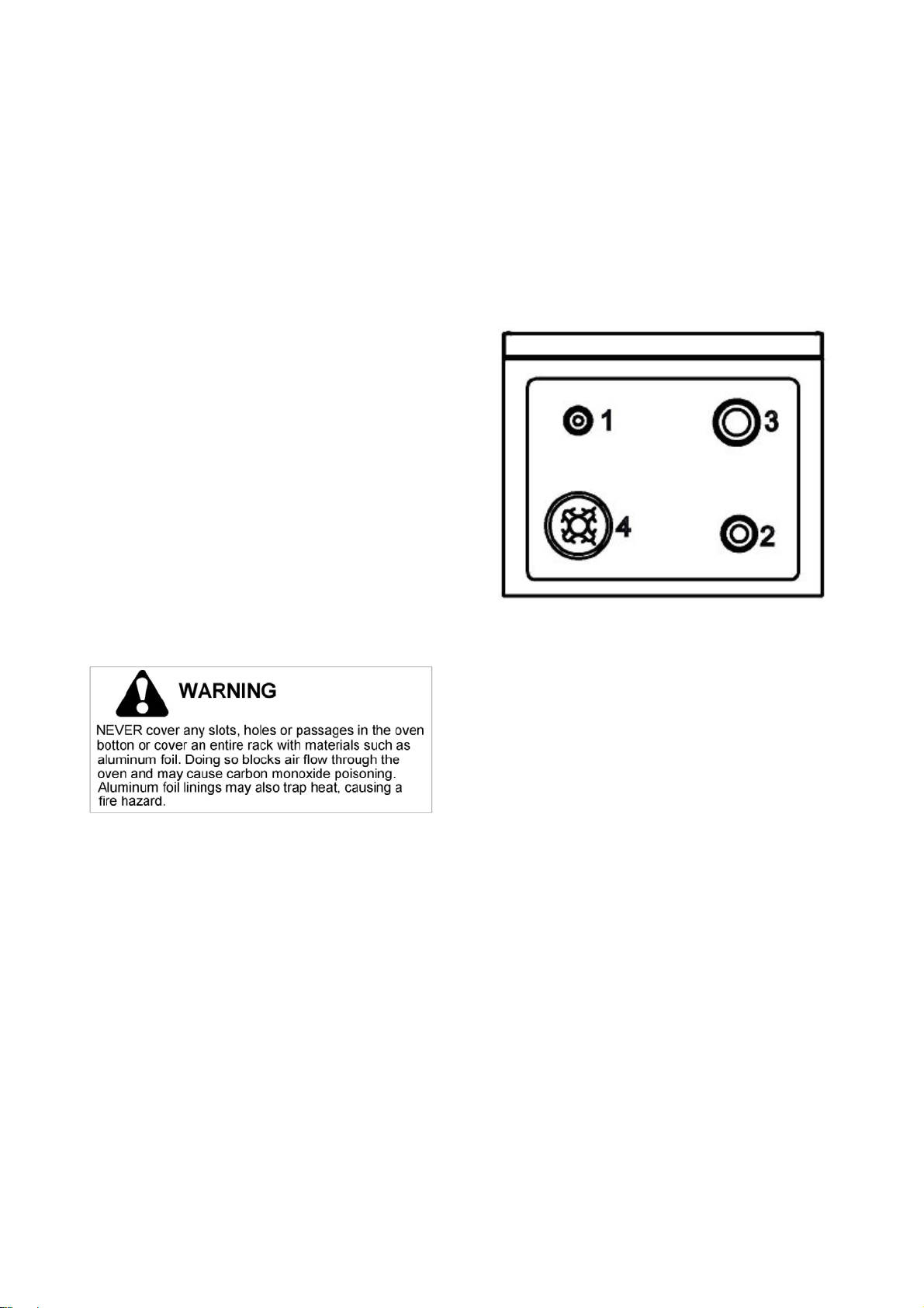
WARNING!
Donottocovertheholesinsidetheovenwith
aluminiumfoil.
Donottocovertheworktopwithaluminium
foil.
Donotstoreanyflammableobjectorobjects
underpressureinthestoragecompartment.
Keeptheareaofoperationoftherangefreefrom
combustiblematerials,gasoline andother
flammablevaporsandliquid.
Donotstoredangerousorflammablematerialsin
thecabinetsabovetheappliance,sincethismay
resultinapotentialfirehazard.
Donotusetheapplianceforspaceheating.
Donotuseaerosolspraysinthevicinityofthe
appliancewhilecooking.
Donotsit
orstepontheovendoor.
Donotuseovencompartmentforstorage.
ROOMVENTILATION
The use of a gas cooking appliance generates
heat and humidity in the room where it is
installed. Proper ventila tion in the room is
needed. Make sure the kitchen is equipped with
a range hood of appropriate power (400 CFM
minimum). Activate the e xhaust fan/range hood
when possible. Intensive and continuous
use of
the appliance may require additional ventilation,
forexamplebyopeningawindow.
SURFACEBURNERLAYOUT
Reflectnamesfrombrochure
1.SmallBurner
2.Mediumburner
3.Rapidburner
4.Dualburner(Powerburner)
21
SURFACECOOKING
IMPORTANT.Takecareofresetall
worktop/oven/broilerburnerscontrolsinOFF
positionafteruseoftheappliance.
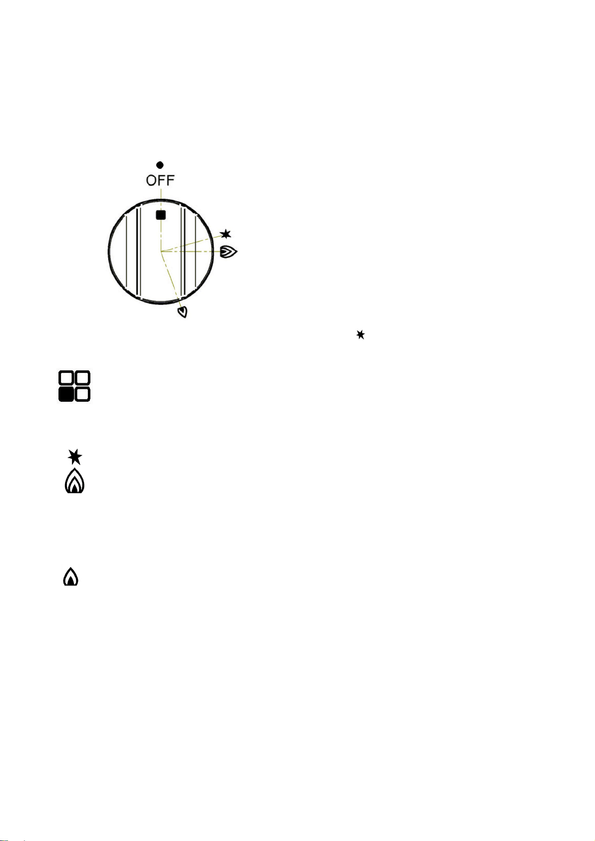
SYMBOLS
Burner position (in this case
frontleftburner).
Maximum temperature
setting / Recommended
control knob position for
burnerignition
Minimumtemperaturesetting
SURFACEBURNEROPERATION
THERMOCOUPLESAFETYVALVE
Each surface burner of a Bertazzoni range is
equippedwithathermocouplesafetydevice.
The thermocouple opens the flow of gas to the
burner only when hot. Should the flame go off,
the thermocouple will immediatelyclose the gas
flow to the burner eliminating any risk to your
home.
Forfasteractivationofthethermocouple,always
light the burners on maximum power. This will
allow the thermocouple to reach the optimum
temperatureinthefastesttime.
ELECTRICIGNITION
To activate the electric ignition, simply turn the
control knob counter‐
clockwise to maximum
power ((
position). Press the knob to start the
flow ofgas and the ignition spark. The sparkwill
releasedatthemetaltipofthewhitecerami cpi n
locatedonthesideoftheburner.Oncetheflame
ison,releasethecontrolknobgently.
If the flame turns off, repeat the
above
procedure.
The dual power‐burner is composed by two
burners (inside and outside). Each burner is
activated by a separate control knob. The two
burners can be operated separately or togethe r
for maximum power. To activate the power‐
burner,turnonthecentralburnerfirst,thenturn
onthe
externalring.
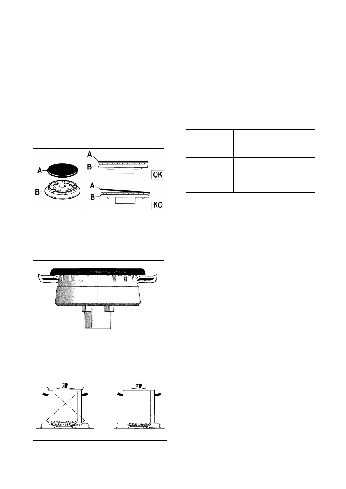
ATTENTION: do not ignite burners if the black
burner cap is not installed or not centred. The
flamewillbeirregular.
MANUALIGNITION
Manualignitionisalwayspossibleevenwhenthe
poweriscutofforintheeventofpowerfailure.
Turn the control knob counter‐clockwise
to the
MAXIMUM position. Light the flame with a
kitchenlighterorwithamatch.
22
TIPSFORUSINGBURNERSCORRECTLY
WARNING!
KEEPCHILDRENATASAFEDISTANCEFROMTHE
APPLIANCEDURINGOPERATION.
DONOTALLOWCHILDRENTOOPERATETHE
APPLIANCE.
IMPORTANT.Takecareofresetall
worktop/oven/broilerburnerscontrolsinOFF
positionafteruseoftheappliance.
1. Always check that the burner caps are
properlyinstalledbeforeoperation.
2. Verify thatthe flameof theworktopburners
be completely blue and with regular aspect
asshownbelow.
3. Alwaysadjust theburnerflamesoitdoes not
extendbeyondtheedgeofthepan.
TIPSFORUSINGPANSCORRECTLY
ATTENTION!
Alwaysensurethatbottomandhandles ofpans
donotprotrudefromtheworktop.
Whencookingwithflammablefatsuchasoil,do
notleavetherangeunattended.
Use pots of the appropriate size on each burner
followingtheindicationofthediagram
below.
When boiling liquids, turn the knob to the
MINIMUM position once boiling is reached to
avoidoverflow..
Alwaysusepotswithmatchinglid.
Drythebottomofpansbeforeoperation.
Usepotswithaflat,thickbottom(exceptforwok
cooking).
WOKCOOKING:alwaysusethewokadapter
suppliedwiththerange.Wokpanexternal
diametershallnotbesmallerthan10”(25cm)
andlargerthan16”(40cm).
SIMMERING:usethesimmerring suppliedwith
therange.
Burner Recommendedpansize
inches(mm)
Small 3½”‐51/2”(90–140)
Medium 51/2”‐101/4”(140–260)
Large 71/8”‐101/4”(180–260)
Dualburner 82/3”‐101/4”(220–260)
23
OVENCOOKING
IMPORTANT.Takecareofresetall
worktop/oven/broilerburnerscontrolsinOFF
positionafteruseoftheappliance.
IMPORTANT:Doesnotobstructthe
oven/broiler’sflowofcombustionoutletslocated
inthebackguardfixedinthebacksideofthe
worktopsincethiscanproducepoisonousexcess
ofcarbonmonoxide.
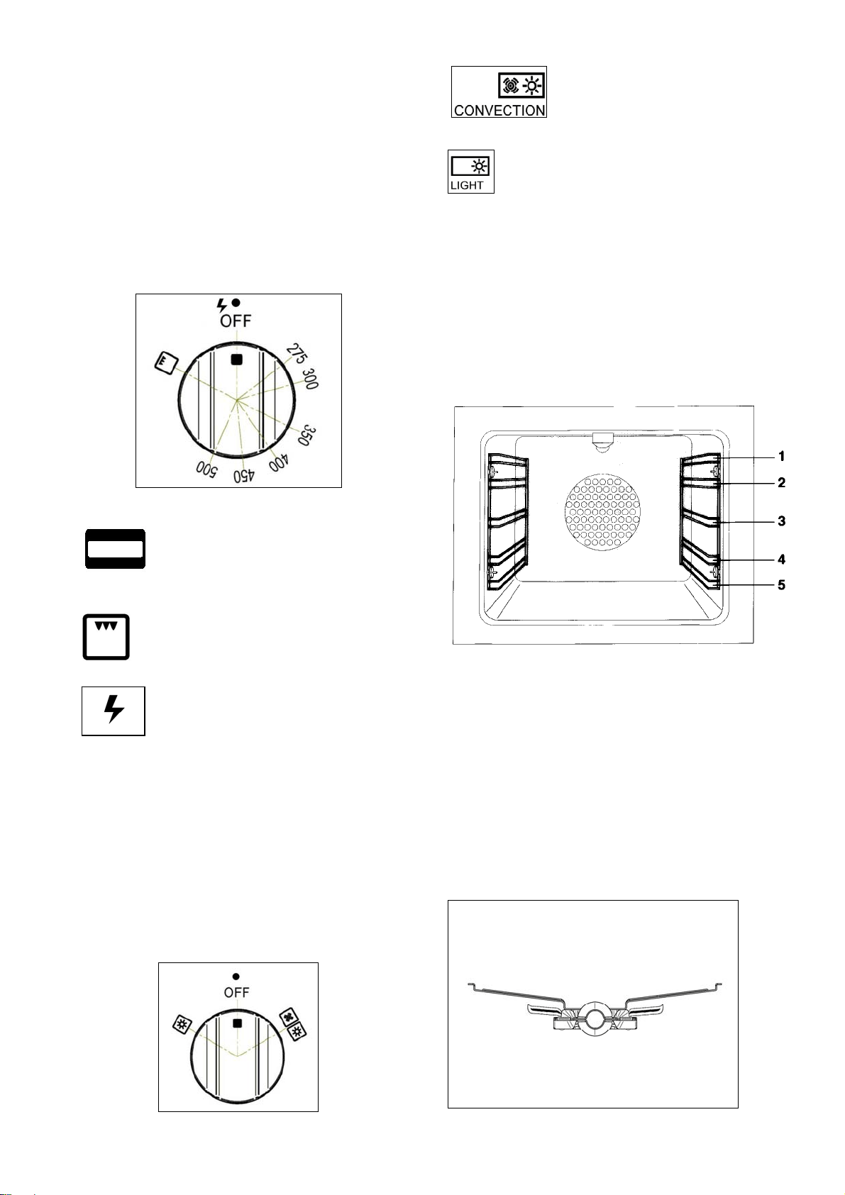
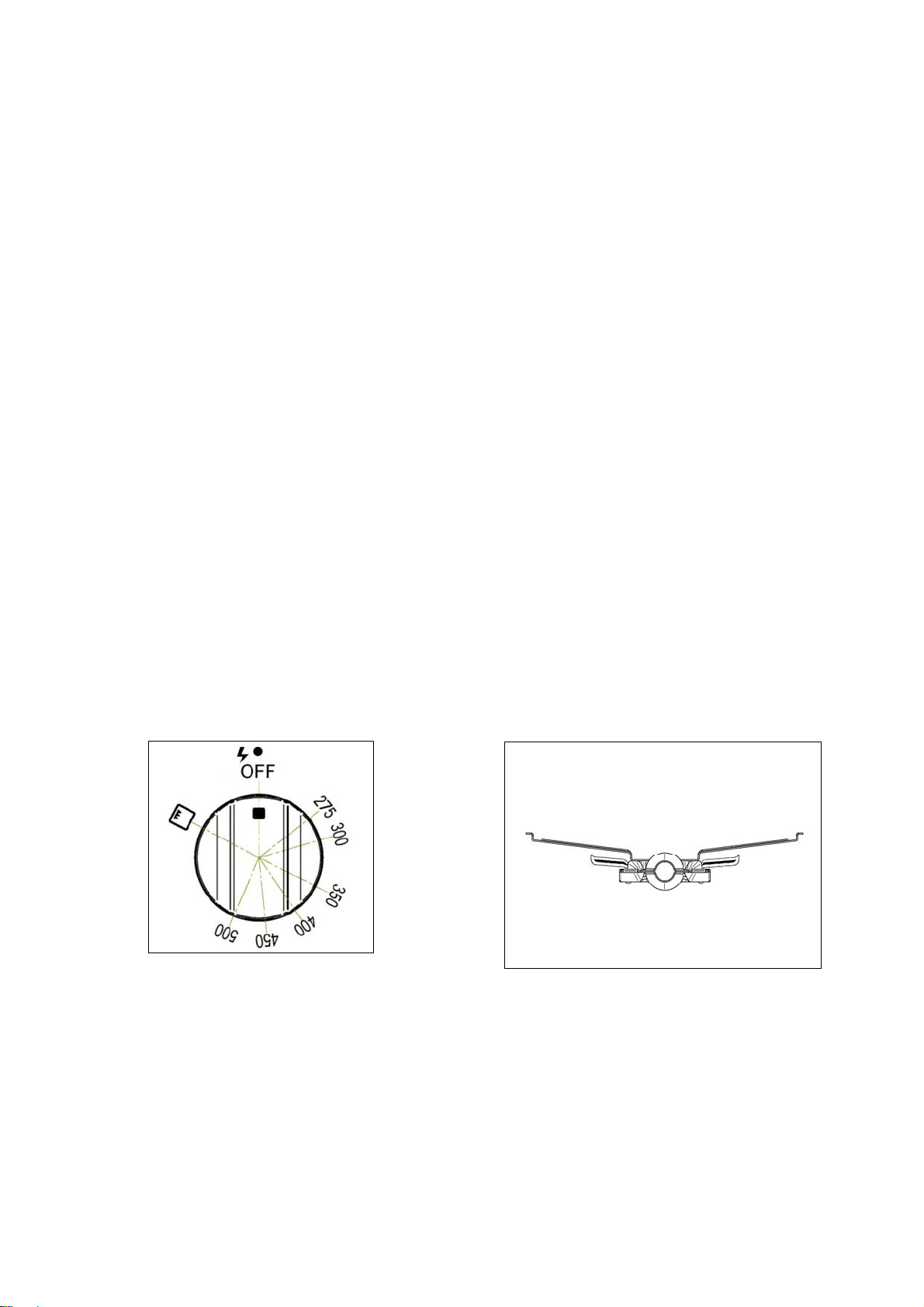
SYMBOLS
Thermalbakeselector
Broilerselector
Recommended con trol knob
positionforburnerignition
275F Mimimum oven temperature
setting
500F Maximum oven temperature
setting
Ovenon/off Ovenstatusindicator.
Convection fan and oven
compartmentlightswitch
Oven compartment light
switchforbakingorbroiling
OVENSHELVES
Bertazzoni rangesareequipped with commercial
gradeshelvesandaenamelcookingtray.
Shelves are mounted on the appropriate guides
situated on the sides of the oven compartment.
Inserttheshelfbetweentopandbottomguidein
anyofthe
5positionsavailable.
Tokeeptheovenascleanaspossible,cookmeat
onthetray.
When available, always follow recipe book
directions. Personal experience will help to
determine any variations in the values reported
in the table. In any case, it is recommended to
followtheinstructionsofthespecificrecipe
being
used.
Verify that the flame of the oven/broiler burner
be completely blue and with regular aspect as
shownbelow.

24
GASOVENOPERATION
IMPORTANT: Does not obstruct the
oven/broiler’sflowofcombustionoutletslocated
in the backguard fixed in the back side of the
worktopsincethiscanproducepoisonousexcess
ofcarbonmonoxide.
THERMOCOUPLESAFETYVALVE
Bertazzoni gas ovens are equipped with a
thermocouple safety device and a thermostat to
setthepropercookingtemperature.
The thermocouple opens the flow of gas to the
burner only when hot. Should the flame go off,
the thermocouple will immediatelyclose the gas
flow to the burner
eliminating any risk to your
home.
Forfasteractivationofthethermocouple,always
light the burners on maximum power. This will
allow the thermocouple to reach the optimum
temperatureinthefastesttime.
ATTENTION!
Whenusingtheovenforthefirsttimeitshould
beoperatedfor15‐30minutes
atatemperature
ofabout500 °F/260°Cwithou tcookinganything
insideinordertoeliminateanymoistureand
odoursfromtheinternalinsulation.
ELECTRICIGNITION
WARNING!
Alwayskeeptheovendooropenwhenlighting
theoven.
Warning:Donotusethegasovenorbroilerin
caseofelectricpower
failure
Open the oven door, with oven/broiler
thermostat knob in the OFF position, press the
thermostatknob for about 1 sec., release it
immediately
and turn it to the desired oven
temperature; in the case when the i gnition of
oven burner does not happen successfully (the
oven burner does not remain alight), turn the
thermostat knob in the OFF position again and
repeat the whole sequence described here one
minutelater
.
The gas oven operation is indicated by a blue
lightontheleftsideofthecontrolpanel.
Before closing the oven door, visually check that
the flame is on through the portholes on the
oven compartment bottom panel. If no flame is
visible,repeattheprocedure.
After lighting the
burner and setting the desired
temperature, wait about 15 minutes before
puttingfoodintopreheattheoven.
WARNING
Iftheovenburnerflameisextinguished
accidentallyduringoperation,turnthe
temperaturecontrolknobcounter‐clockwiseto
theoffposition.Waitatleast60secondsbefore
attemptingtolightthe
ovenagain.
IMPORTANT:Incaseofelectricpowerfailure
resetoven/broilercontrolsinoffposition.
Oven/broiler burners cannot operates till when
electric power to the appliance has been
restored.
25
CONVECTIONCOOKING
Bertazzoni gas oven are equipped with a
CONVECTIONfan.
Inconvectionmode, thefan situatedat theback
of the oven compartment creates horizontal
forced‐air circulation. The advantages of
convectioncookingare:
1. uniform distribution of heat throughout the
oven cavity (meat no longer needs to be turned
whileroasting)
2. cooking different types of food at the same
time,withoutflavourtransmissionfromonedish
totheother.
Pre‐heating the oven is not necessary. For
delicatepastrybaking,itisrecommendedtoheat
theovenbeforeinsertingthepastrytrays.
Toactivatetheconvectionfanuse
theselector
placedoncontrolpanel.
COOKINGWITHTHEGASBROILER
IMPORTANT: Does not obstruct the
oven/broiler’sflowofcombustionoutletslocated
in the backguard fixed in the back side of the
worktopsincethiscanproducepoisonousexcess
ofcarbonmonoxide.
ELECTRICIGNITION
Open the oven door, with oven/broiler
thermostat knob in the OFF position, press the
thermostatknob for about 1 sec., release it
immediately
and turn it to the broiler position; in
thecasewhentheignitionofbroilerburnerdoes
not happen successfully (the broiler burner does
not remain alight), turn the thermostat knob in
the OFF position again and repeat the whole
sequencedescribedhereoneminutelater
.
Before closing the oven door, visually check that
the flame is on through the portholes on the
oven compartment bottom panel. If no flame is
visible,repeattheprocedure.
ATTENTION: always use the small wire shelf
inside the enamel tray supplied with the range;
positionthetrayonthetop
ovenshelf.
Gasbroiler operationisindicatedbytheindicator
ontheleftsideofthecontrolpanel.
IMPORTANT: when broiling food keep the door
closed.
IMPORTANT: In case of electric power failure
resetoven/broilercontrolsinoffposition.
Oven/broiler burners cannot operates till when
electric power to the appliance has
been
restored.
Verify that the flame of the oven/broiler burner
be completely blue and with regular aspect as
shownbelow.

26
MAINTAININGYOURRANGE
REPLACINGTHEOVENLIGHTBULB
WARNING!
Disconnectpowerbeforeservicingunit.
To replace the oven light bulb, unscrew the
protectioncapthatprojectsoutinsidetheoven.
Spare bulbs are available at factory‐authorized
partsresellerslistedonpage4.
Alternatively use comm ercial bulbs type [list
SPECS]
COOLINGFANFAILURE
Bertazzoni ranges are equipped with a cooling
fan. The fan starts operating each time the oven
knobisonapositiondifferentfrom0(zero).
The fancirculates the air between the control
panel and the oven door, allowing the control
panel and the oven door
to remain cool while
cooking.
Malfunctionofthecoolingfanisindicatedbythe
FANFA ILURElight situatedat theleft side ofthe
control panel. If the light is on, turn off all
burnersassoonaspossibleandcallthecustomer
service hotline to schedule service by a factory
‐
trainedprofessional.
CLEANINGYOURRANGE
ATTENTION: during cleaning operation never
move the appliance from its foreseen original
installationposition.
ATTENTION!Neveruseabrasivecleaners!
Scratches on the stainless steel surfaces are
permanent.
Donotcleantherangewhenhot!
Cleaning after installation: use a stainless steel
cleaning product or wipe to eliminate the glue
residues of the blue protection film after
removal.
Cleaning the worktop: periodically clean the
burnerheads,
thecastironpansupportsandthe
burner caps using warm water. Remove burned
food and fat residues with a rubber spatula . If
food residue prevent the smooth operation of
the control knobs, call the customer servce
hotline to schedule service by a factory‐trained
professional.
Cleaning stainless steel:
for best results use a
stainlesssteelcleanerproductwithasoftsponge
or wipe. Alternatively use a soft sponge or cloth
witha warm soapandwatersolution. Neveruse
abrasivepowdersorliquids!
Cleaning the burner caps: lift the burner caps
fromtheburnerheadsandwashthemin
awarm
soap and water solution. Dry thoroughly before
usingthemagain.Beforereinstallingthemonthe
burner head, check that the gas flow holes are
not clogged with food residues or cleaning
productresidues.
Cleaning Enamel: enamelled parts should be
cleaned frequently with awarm soap and water
solution applied
with a soft sponge or wipe.
Never use abrasive powders or liquids! Do not
leave acid or alkaline substances on the
enamelled parts (such as vinegar, lemon juice,
salt,tomato sauce,etc.). Usearubberspatula to
removefatresidues.
Cleaning glass door:cleantheglass using a non‐
abrasive sponge
or wipe with a warm soap and
warm water solution. Use a rubber spatula to
removefatresidues.
ATTENTION: while cleaning the door, avoid
spillage of food resideues and cleaning products
in the venting holes situated on the top side of
the door. To clean the inside of the oven
door,
callafactory‐trainedprofessional.
ATTENTION:for furtherdetails aboutcleaning of
the appliance, please contact your appliance
retailer.

27
IMPORTANTAPPLIANCEINFORMATION
MODEL ______________________________________________________________
DATEINSTALLED _______________________________________________________________
DEALER _______________________________________________________________
_______________________________________________________________
INSTALLER _______________________________________________________________
_______________________________________________________________ _
SERVICER _______________________________________________________________
_______________________________________________________________ _

28
BERTAZZONISpA
ViaPalazzina8
42016GuastallaRE
ITALY
WWW.BERTAZZONI.COM
3100129