OPERATION AND INSTALLATION
FUNCIONAMIENTO E INSTALACIÓN
Electronically Controlled Electric Tankless Water Heaters
Calentadores de Agua Electrónicos sin Tanque
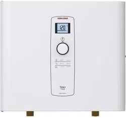
» DHX 3.5-1 Trend
» DHX 6-2 Trend
» DHX 8-2 Trend
»DHX 10-2 Trend
»DHX 12-2 Trend
»DHX 15-2 Trend
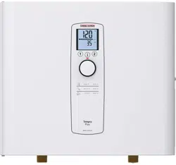
»DHX 12-2 Plus
»DHX 15-2 Plus
Certified to ANSI/UL Std. 499
Conforms to CAN/CSA Std. C22.2 No. 64
Certificación ANSI/UL Std. 499
Conforme a CAN/CSA Std. C22.2 No.64
Tested and certified by WQA to NSF/ANSI372
for lead free compliance.
Probado y certificado por WQA NSF/ANSI 372 para
el cumplimiento de las regulaciones sin plomo.
i

2 | DHX Trend & DHX Plus www.stiebel-eltron-usa.com
CONTENTS
QUICK START GUIDE
SPECIAL INFORMATION
OPERATION
1. General information ___________________________________________ 5
1.1 Safety instructions __________________________________________________ 5
1.2 Other symbols in this documentation __________________________ 5
1.3 Units of measurement _____________________________________________ 5
2. Safety ____________________________________________________________ 5
2.1 Intended use _________________________________________________________ 5
2.2 General safety instructions _______________________________________ 5
2.3 Test symbols _________________________________________________________ 6
2.4 Licenses / certificates ______________________________________________ 6
3. Register your product _________________________________________ 6
4. Water heater description ______________________________________ 7
5. Settings and displays __________________________________________ 7
5.1 DHX Trend user interface _________________________________________ 7
5.2 DHX Plus user interface ___________________________________________ 8
5.3 Using the display menus __________________________________________ 8
5.4 DHX Trend display __________________________________________________ 8
5.5 DHX Plus display ____________________________________________________ 9
5.6 Recommended settings __________________________________________12
6. Cleaning, care and maintenance ____________________________12
7. Troubleshooting _______________________________________________13
INSTALLATION
8. Safety ___________________________________________________________13
8.1 General safety instructions ______________________________________13
8.2 Instructions, standards and regulations ______________________13
9. Water heater description _____________________________________13
9.1 Standard delivery __________________________________________________13
10. Preparation ____________________________________________________14
10.1 Installation site _____________________________________________________14
10.2 Minimum clearances ______________________________________________14
11. Installation _____________________________________________________14
11.1 Standard wall-mounted installation ___________________________14
11.2 Water connections _________________________________________________15
11.3 Aerator installation at connected faucet ______________________16
11.4 Electrical connection ______________________________________________16
11.5 Electrical connection with short power cable _______________17
11.6 Wiring block ________________________________________________________17
12. Commissioning ________________________________________________ 17
12.1 Internal anti-scalding protection via jumper slot ___________17
12.2 Initial start-up ______________________________________________________17
12.3 Operation with preheated water _______________________________18
12.4 Recommissioning __________________________________________________18
13. Water heater shutdown ______________________________________18
14. Service information ___________________________________________19
15. Maintenance ___________________________________________________19
15.1 Draining the water heater _______________________________________19
15.2 Cleaning the filter screen ________________________________________19
16. Troubleshooting _______________________________________________20
17. Specification ___________________________________________________21
17.1 Dimensions and connections ____________________________________21
17.2 Wiring diagrams ___________________________________________________21
17.3 Hot water output ___________________________________________________22
17.4 Application areas/conversion table ____________________________22
17.5 Fault conditions ____________________________________________________22
17.6 Data table ___________________________________________________________23
18. Spare parts ____________________________________________________24
19. Warranty _______________________________________________________25
QUICK START GUIDE
ENGLISH
www.stiebel-eltron-usa.com DHX Trend & DHX Plus | 3
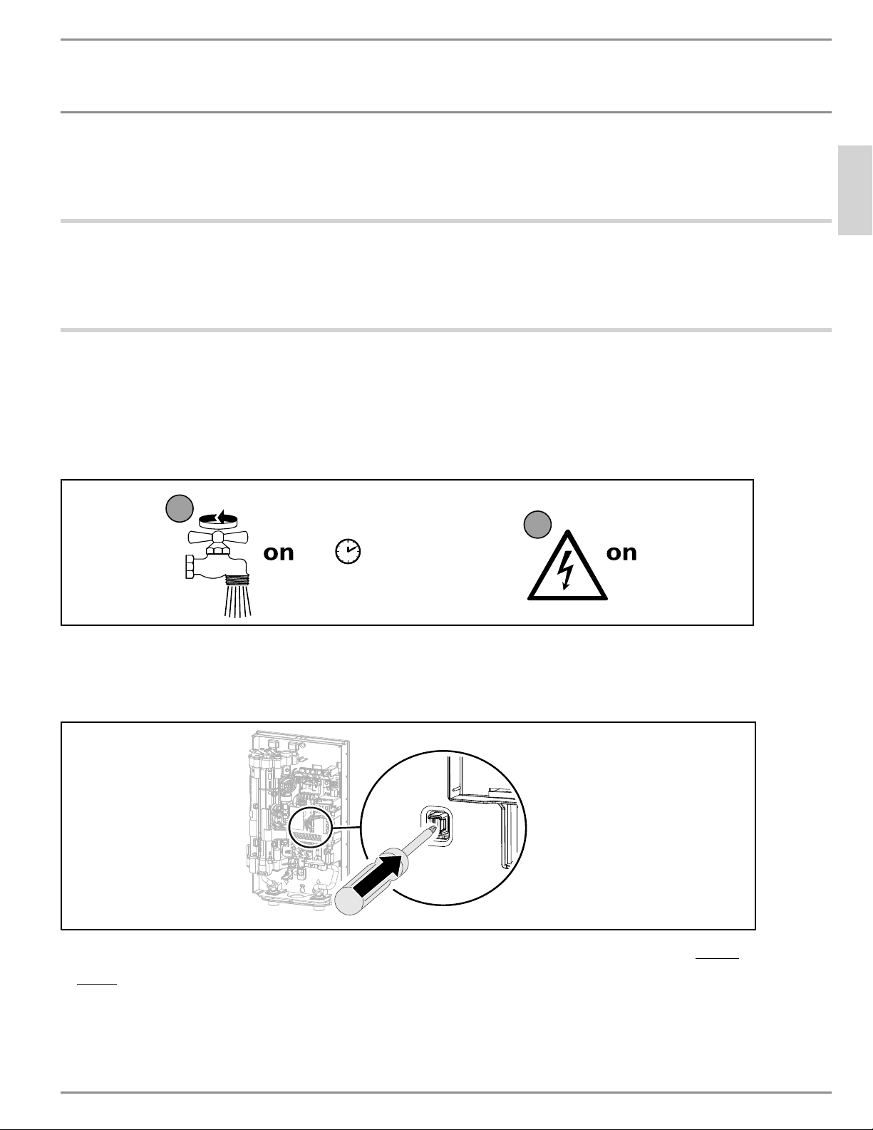
QUICK START GUIDE
Before turning on power to the water heater, you MUST flush all air out of the
system, then engage the AE3 safety switch. The unit will NOT operate until
the AE3 safety switch has been engaged.
1 Mount the unit to the wall (see section 11.1, “Standard wall-mounted installation”, pg. 14).
2 Hook up water connections (see section 11.2, “Water connections”, pg. 15).
3 Hook up electrical connections, but keep circuit breaker off. (See section 11.4, “Electrical connec-
tion”, pg. 16)
PLQ
1
2
D0000053277
4 Open and close all connected draw-off valves at least 5 times, for at least 3 minutes total,
until all air has been purged from the pipework and the water heater.
5 Ensure there are no water leaks from any plumbing connections.
D0000094561-b
6 Engage the AE3 safety switch by firmly pressing the white reset button until it clicks and fully
locks in place (the water heater is delivered with the safety switch disengaged).
7 Turn on power to the water heater at the circuit breaker in the breaker panel.

SPECIAL INFORMATION
4 | DHX Trend & DHX Plus www.stiebel-eltron-usa.com
SPECIAL INFORMATION
- Read this entire manual. Failure to follow all the
guides, instructions and rules could cause personal
injury or property damage. Improper installation, ad-
justment, alteration, service and use of this unit can
result in serious injury.
- This unit must be installed by a licensed electrician
and plumber. The installation must comply with all
national, state and local plumbing and electric codes.
Proper installation is the responsibility of the install-
er. Failure to comply with the installation and operat-
ing instructions or improper use voids the warranty.
- Save these instructions for future reference. The
installer should leave these instructions with the
consumer.
- If you have any questions regarding the installation,
use or operation of this water heater, or if you need
any additional installation manuals, please call our
technical service line at 800.582.8423 (USA and Can-
ada only). If you are calling from outside the USA or
Canada, please call USA 413.247.3380 and we will
refer you to a qualified Stiebel Eltron service repre-
sentative in your area.
- The water heater is suitable for supplying a shower in
many climates (shower operation). If the water heater
is also or exclusively used for shower operation, the
qualified contractor must adjust the temperature set-
ting range to 122 °F (50 °C) or less using the internal
anti-scalding protection on the water heater. When
using preheated water, it must be ensured that the
inlet temperature does not exceed 131 °F (55 °C).
- Ensure the water heater can be separated from the
power supply by a circuit breaker that disconnects all
poles with at least 1/8˝ (3mm) contact separation.
- The specified voltage must match the power supply.
See the type plate on the right-hand side of the water
heater for full information.
- CAUTION: DO NOT INSTALL IN A BATH ENCLOSURE OR
SHOWER STALL.
DO NOT CONNECT TO A SALT-REGENERATED WATER
SOFTENER OR A SALT-WATER WATER SUPPLY.
FOR USE ON AN INDIVIDUAL BRANCH CIRCUIT ONLY.
CAUTION: CONNECT ONLY TO A CIRCUIT PROTECTED
BY A CLASS A GROUND FAULT INTERRUPTER
USE BONDING CONDUCTOR IN ACCORDANCE WITH
THE CANADIAN ELECTRICAL CODE, PART I
- The water heater must be properly grounded. See
section 17.2, “Wiring diagrams,” pg. 21.
- The water heater must be permanently connected to
fixed wiring. For use on an individual branch circuit
only. See section 17.2, “Wiring diagrams,” pg. 21.
- Secure the water heater as described in chapter 11,
“Installation”, pg. 14.
- Observe the minimum permissible water supply
pressure of 26.1 psi (1.8 bar). See section 17.6, “Data
table,” pg. 23.
- Observe the maximum permissible water supply
pressure of 145 psi (10 bar). See section 17.6, “Data
table,” pg. 23.
- Drain the water heater as described in section 15.1,
“Draining the water heater”, pg. 19.
OPERATION
General information
ENGLISH
www.stiebel-eltron-usa.com DHX Trend & DHX Plus | 5
OPERATION
1. General information
The chapters "Special information" and "Operation" are intended for
both users and qualified contractors.
The chapter "Installation" is intended for qualified contractors.
Note
Read these instructions carefully before using the water
heater and retain them for future reference.
Pass on the instructions to a new user if required.
1.1 Safety instructions
1.1.1 Structure of safety instructions
!
KEYWORD Type of risk
Here, possible consequences are listed that may result
from failure to observe the safety instructions.
f Steps to prevent the risk are listed.
1.1.2 Symbols, type of risk
Symbol Type of risk
Injury
Electrocution
Burns
(burns, scalding)
1.1.3 Keywords
KEYWORD Meaning
DANGER Failure to observe this information will result in serious in-
jury or death.
WARNING Failure to observe this information may result in serious
injury or death.
CAUTION Failure to observe this information may result in non-serious
or minor injury.
1.2 Other symbols in this documentation
Note
General information is identified by the adjacent symbol.
f Read these texts carefully.
Symbol Meaning
Material losses
(water heater damage, material losses, and installation site
damage)
f This symbol indicates that you have to do something. The ac-
tion you need to take is described step by step.
1.3 Units of measurement
Note
All measurements are given in inches (millimeters) unless
otherwise stated.
2. Safety
2.1 Intended use
This water heater is suitable for heating domestic hot water or for
reheating preheated water. The water heater can supply one or
more draw-off points.
Water will not be reheated if the maximum inlet temperature for
reheating is exceeded.
The water heater is intended for domestic use. It can be used safely
by untrained persons. The water heater can also be used in non-do-
mestic environments, e.g. in small businesses, as long as it is used
in the same way.
Any other use beyond that described shall be deemed inappropriate.
Observation of these instructions and of the instructions for any
accessories used is also part of the correct use of this water heater.
2.2 General safety instructions
DANGER: Burns
Water temperatures over 125 °F (52 °C) can cause severe
burns instantly or death from scalding. A hot water scald-
ing potential exists if the thermostat on the water heater
is set too high. Households with small children, disabled
or elderly persons may require that the thermostat be set
at 113 °F (45 °C) or lower to prevent possible injury from
hot water.
CAUTION: Burns
If operating with preheated water, e.g.from a solar ther-
mal system, the DHW temperature may vary from the
selected set temperature.
!
!
OPERATION
Register your product
6 | DHX Trend & DHX Plus www.stiebel-eltron-usa.com
CAUTION: Burns
During operation, the tap can reach temperatures up to
149 °F (65 °C).
There is a risk of scalding at outlet temperatures in excess
of 110 °F (43 °C).
!
DANGER: Injury
Please read and follow these instructions. Failure to follow
these instructions could result in serious personal injury
or death.
!
CAUTION: DO NOT INSTALL IN A BATH ENCLOSURE
OR SHOWER STALL. DO NOT CONNECT TO A
SALT-REGENERATED WATER SOFTENER OR A WATER
SUPPLY OF SALT WATER.
FOR USE ON AN INDIVIDUAL BRANCH CIRCUIT ONLY.
CAUTION: CONNECT ONLY TO A CIRCUIT PROTECTED BY A
CLASS A GROUND FAULT INTERRUPTER
USE BONDING CONDUCTOR IN ACCORDANCE WITH THE CA-
NADIAN ELECTRICAL CODE, PART I
DANGER: Electrocution
Before proceeding with any installation, adjustment,
alteration, or service of this appliance, all circuit break-
ers and disconnect switches servicing the appliance
must be turned off. Failure to do so could result in seri-
ous personal injury or death.
DANGER: Electrocution
Never remove the water heater’s cover unless the elec-
tricity servicing the water heater is turned off. Failure to
do so could result in personal injury or death.
WARNING Electrocution
The connection to the power supply is only permissible as
a permanent connection in conjunction with a ¾˝ Romex
clamp. Ensure the water heater can be separated from
the power supply by an isolator that disconnects all poles
with at least 1/8˝ (3mm) contact separation.
!
WARNING: Injury
Where children or persons with limited physical, sensory
or mental capabilities are to be allowed to control this
water heater, ensure that this will only happen under su-
pervision or after appropriate instructions by a person re-
sponsible for their safety. Children should be supervised to
ensure that they never play with the water heater.
!
DAMAGE TO THE WATER HEATER AND THE ENVIRON-
MENT:
The water heater must be installed by a licensed electrician
and plumber. The installation must comply with all nation-
al, state and local plumbing and electric codes.
Service of the water heater must be performed by qualified
service technicians.
!
DAMAGE TO THE WATER HEATER AND THE ENVIRON-
MENT:
Supply this appliance only from a grounded system. A
green terminal (or a wire connector marked “G”, “GR”,
“GROUND”, OR “GROUNDING”) is provided for wiring the
appliance. To reduce the risk of electric shock, connect
this terminal or connector to the grounding terminal of the
electric service or supply panel with a continuous copper
wire in accordance with the electrical installation code.
Where children or persons with limited physical, sensory or mental
abilities are allowed to use this water heater, we recommend a
permanent temperature limit. The following limitation options are
available:
- All DHX models - qualified contractor adjustable: “Internal
anti-scalding protection”
- DHX Plus only - user adjustable: Temperature limit
(childproofing)
!
Material losses
The user should protect the water heater against frost.
2.3 Test symbols
See type plate on the water heater.
2.4 Licenses / certificates
- UL (USA) Std. 499
- CSA (Canada) Std. C22.2 No. 64
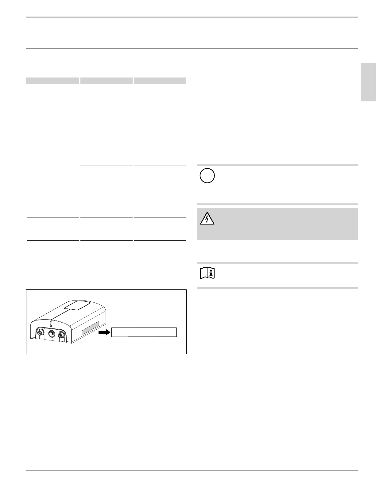
3. Register your product
You must register this product within 90 days of pur-
chase on our web site in order to activate the standard
warranty. Go to our web site at
www.stiebel-eltron-usa.com and click on “Register
Your Product.”
Before beginning the registration process, we suggest that you
gather the necessary information which will be as follows:
Type, Example: DHX 15-2 Plus (from the label that is on the unit)
Number listed after “Nr.”
Place of Purchase
Purchase Date
First & Last Name
Email address
Physical Address
Phone Number
Installation Date
If you have any questions concerning the registration pro-
cess or warranty, please contact Stiebel Eltron USA directly at
800.582.8423.
OPERATION
Water heater description
ENGLISH
www.stiebel-eltron-usa.com DHX Trend & DHX Plus | 7
4. Water heater description
The water heater switches on automatically as soon as a hot water
valve at a tap or other draw-off point is opened. DHX heats water as
it flows through the unit. When the tap is closed, the water heater
switches off automatically.
From the activation flow rate, the electronic control unit regulates
the correct heating output using only the minimum amount of power
necessary, subject to the temperature selected and the current in-
coming cold water temperature.
DHX Trend and DHX Plus are electronically controlled tankless water
heaters, and maintain a consistent outlet temperature. This is irre-
spective of the inlet water temperature, up to the maximum output
of the water heater.
DHX Plus models feature Advance Flow Control
™
, a technology pat-
ented by Stiebel Eltron in Germany (patent no. DE 3805441 C2). When
the maximum output of a DHX Plus model is met, rather than deviate
from the setpoint temperature and deliver cooler water, DHX Plus
models use an electronically-controlled motorized valve to slightly
reduce the flow of water only as much as is necessary to maintain
the user-selected temperature. When the demand can again be fully
met, the motorized valve returns to the fully open position, allowing
the full flow rate. This ensures uninterrupted comfort, and hot water
delivered at the desired temperature at all times.
If the water heater is operated with preheated water, and the inlet
temperature exceeds the selected set temperature, the inlet tem-
perature will be displayed on the second row of the screen (DHX
Plus models only) and will flash. The water is not heated further.
DHX models are equipped with functions to permanently limit the
temperature (childproofing).
DHX Plus models feature a backlit display that switches on auto-
matically as soon as water flows through the unit, or if a change is
made at the user interface. The backlight switches off automatically
if no changes are made for 30seconds, or 5seconds after hot water
stops being drawn.
DHX Plus models allow the user to save different preset tempera-
tures and apply them quickly.
DHX Plus models also offer a more in-depth 2-line display with
enhanced functions. The DHX Trend has a single-line display and a
more basic user feature set.
Domestic Hot Water (DHW) temperature
The DHW outlet temperature can be variably adjusted from 68–140 °F
(20–60 °C). The selected temperature is displayed.
Heating system
The Direct Coil
™
heating system is comprised of a pressure-tested,
glass-reinforced polyamide heating chamber with a nichrome wire
direct heating coil. It is suitable for hard and soft water areas and
is largely insusceptible to scale build-up. The Direct Coil
™
heating
system ensures rapid and efficient DHW production.
Note
The water heater is equipped with an air detector that
largely prevents damage to the heating system. If, during
operation, air is drawn into the water heater, the water
heater shuts down the heating output for one minute to
protect the heating system.
5. Settings and displays
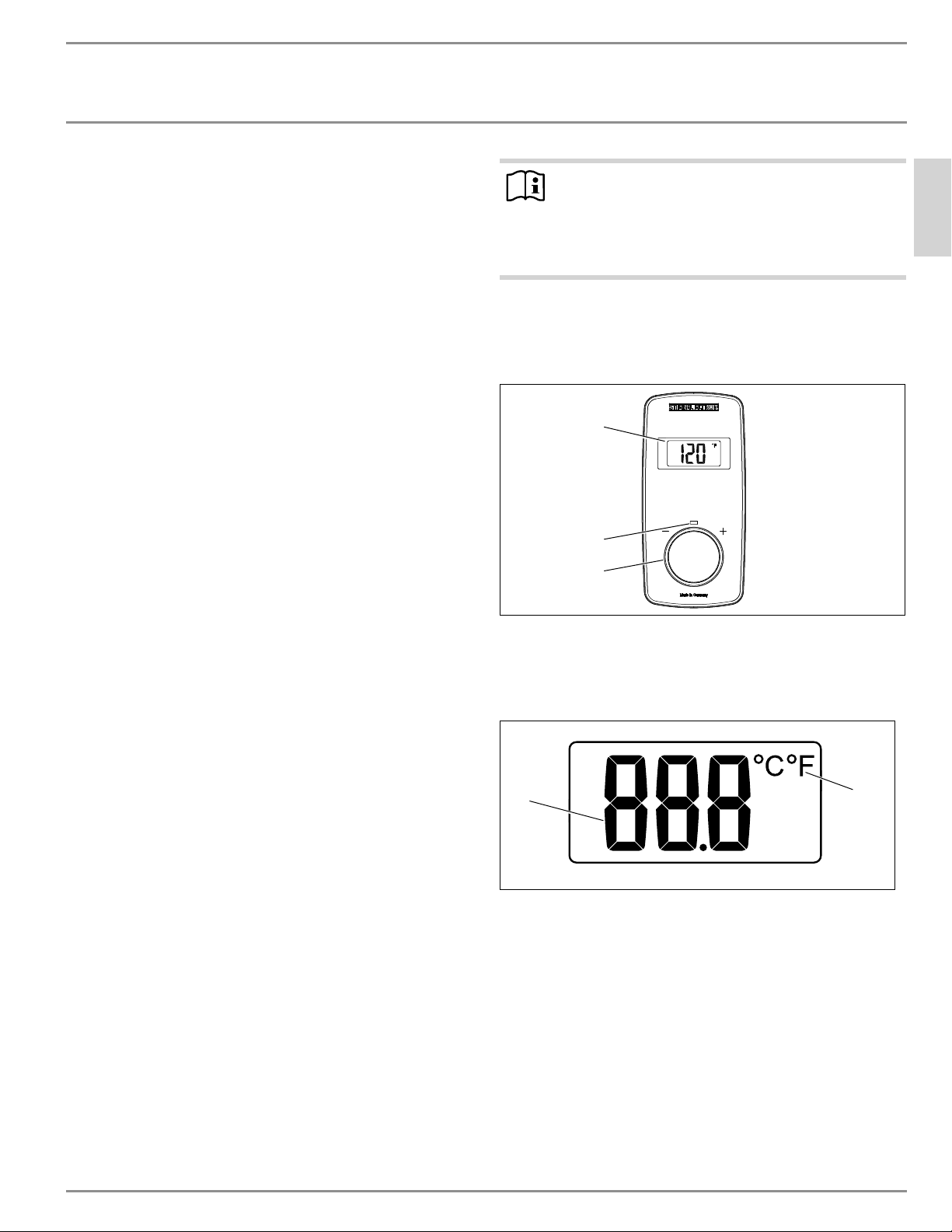
5.1 DHX Trend user interface
2
3
1
1 Display
2 Operating LED (flashes when output limit is reached)
3 Control knob
5.1.1 DHX Trend display overview
1
2
1 Digit display
2 Temperature unit indicator
OPERATION
Settings and displays
8 | DHX Trend & DHX Plus www.stiebel-eltron-usa.com
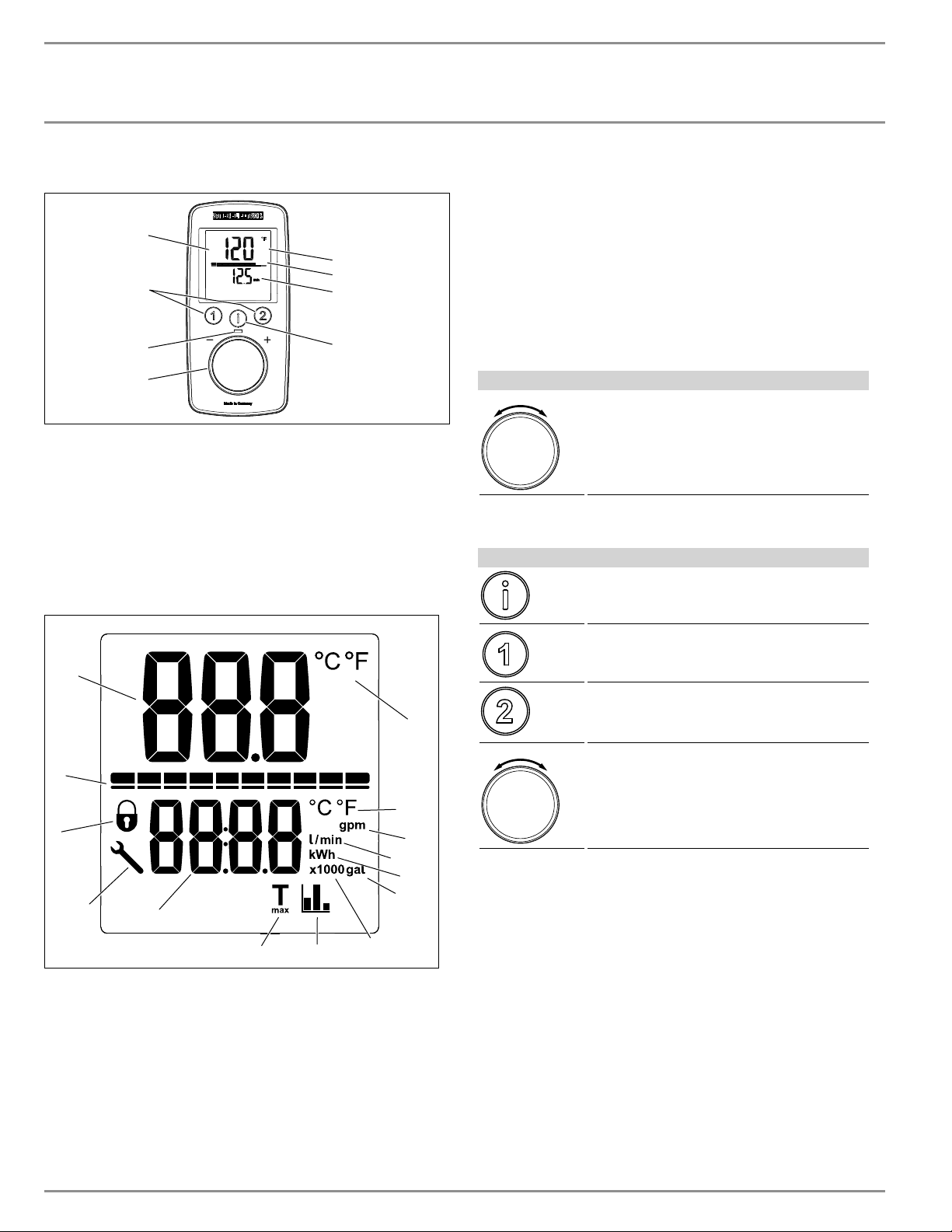
5.2 DHX Plus user interface
D0000073619
2
3
1
8
5
6
7
4
1 Control knob
2 Operating LED (flashes when output limit is reached)
3 Temperature memory keys
4 Backlit display
5 Main display | info display | parameter display
6 Segment display [10–100%]
7 Second row of screen
8 “i” button to retrieve information and select menus
5.2.1 DHX Plus display overview
1
2
3
4
6
7
8
9
10
11
12
13
14
5
1 Primary digit display
2 Power capacity status
3 Display-lock indicator
4 Error code symbol
5 Secondary digit display
6 T
max
indicator
7 Savings statistics indicator
8 x1000 secondary display value
9 Gallons secondary display unit
10 kWh secondary display unit
11 Liters & liters per minute secondary display unit
12 Gallons per minute secondary display unit
13 Temperature unit for secondary display
14 Temperature unit for primary display
5.3 Using the display menus
The DHX Trend and DHX Plus feature an interactive display that allow
for user customization to increase the level of comfort for the user.
The menu structure is designed in an intuitive, linear way to make
it as navigable as possible.
5.3.1 DHX Trend user input
User input
Control knob (turn knob to change settings)
5.3.2 DHX Plus user input
User input
Information button (pressing or holding this
button performs different functions)
Preset 1 button (pressing or holding this but-
ton performs different functions)
Preset 2 button (pressing or holding this but-
ton performs different functions)
Control knob (turn knob to change settings)
5.4 DHX Trend display
The DHX Trend display features a temperature readout capable of
showing the currently selected temperature in either Fahrenheit
or Celsius.
For the name of each display element on the DHX Trend, consult
section 5.1.1, “DHX Trend display overview”, pg. 7.
OPERATION
Settings and displays
ENGLISH
www.stiebel-eltron-usa.com DHX Trend & DHX Plus | 9
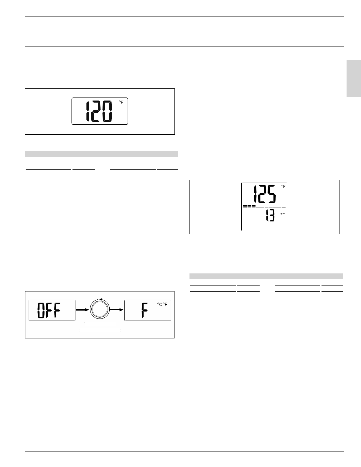
5.4.1 Base display
The base display shows the current temperature setpoint in your
preferred temperature unit.
Changing the setpoint temperature
Temperature settings
Range Increment Range Increment
68–140 °F 1 °F 20–60 °C. 1 °C
The setpoint temperature can be set between 68 °F (20 °C) and 140 °F
(60 °C).
The setpoint can be increased by turning the control knob clockwise,
and decreased by turning it counter-clockwise. The water heater
can be deactivated while still powered by turning the control knob
counter-clockwise, past the 68 °F (20 °C) setting.
5.4.2 Temperature units parameter setting
The DHX Trend is capable of displaying temperature in either Fahr-
enheit or Celsius.
f To change between Fahrenheit (default) and Celsius, first rotate
the control knob to the left until the display reads “Off.”
f Once “Off” is showing on the display, turn the control knob 5
full 360° rotations to the left. This will open the temperature
parameter menu:
Turn full 360°
5 times to the left
Turn full 360°
5
t
i
mes to the le
f
t
The current unit will be shown and the display will be flashing to
indicate that the value can be changed. Rotate the control knob to
change the value between Fahrenheit and Celsius.
5.4.3 Returning to the base display
The display will revert to the base display after a 30-second period
with no user input.
5.5 DHX Plus display
The DHX Plus features a primary and secondary display area al-
lowing for multiple parameters or information to be displayed. The
DHX Plus is capable of displaying the current flow rate of the water
passing through the water heater, as well as calculating the accu-
mulated cost savings of having a tankless water heater compared
to a tank-type water heater.
For the name of each display element on the DHX Plus, consult
section 5.2.1, “DHX Plus display overview”, pg. 8.
5.5.1 Base display
The DHX Plus base display shows the current setpoint temperature
in your preferred temperature unit in the top half of the display.
The bar below the temperature shows the current fraction of total
capacity that the water heater is running at. As the hot water demand
fluctuates, the power capacity status will change to show between
0 and 10 segments. The display below shows that the water heater
is operating at 30% of full capacity.
The bottom half of the display shows the current flow rate through
the unit in either gallons per minute (gpm) or liters per minute (l/
min).
All other menus will revert back to the base display either after a
15-second period of time without user input, or after a 5-second
hold of the Information button.
Changing the setpoint temperature
Temperature settings
Range Increment Range Increment
68–140 °F 1 °F 20–60 °C 0.5 °C
The setpoint temperature can be set between 68 °F (20 °C) and 140 °F
(60 °C).
The setpoint can be increased by turning the control knob clockwise,
and decreased by turning it counter-clockwise. The water heater
can be deactivated while still powered by turning the control knob
counter-clockwise, past the 68 °F (20 °C) setting.
5.5.2 Information menu
The information menu structure displays additional information for
the user. The information menu is accessed by pressing the Infor-
mation button while at the base display.
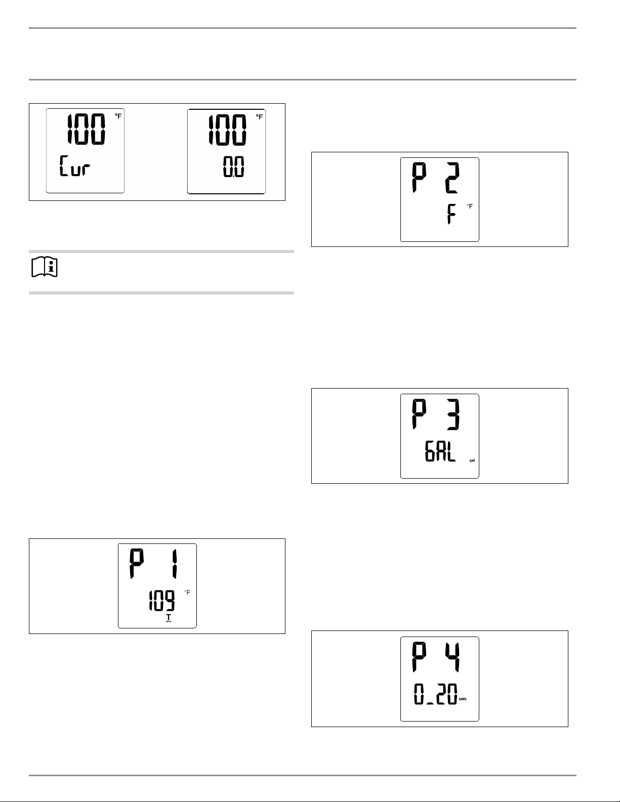
Accumulated cost savings display
If the Information button is pressed while the display is showing
the base display, the display will advance to the accumulated cost
savings display.
The accumulated cost savings display will display the current set-
point temperature in the top half of the display, and the bottom half
of the display will alternate between “Cur” and the accumulated
savings of the water heater.
OPERATION
Settings and displays
10 | DHX Trend & DHX Plus www.stiebel-eltron-usa.com
The accumulated cost savings updates daily, and shows the esti-
mated savings for the user compared to an installation where a
50-gallon tank-type water heater was used.
Note
The energy saving values are calculated starting from the
last reset.
This savings estimate is based on the users electricity cost. For the
most accurate estimate, the electricity cost per kWh should be set in
the electricity cost parameter setting menu. For information on how
to do this, see section “Electricity cost parameter setting”, pg. 10.
Pressing the Information button will advance back to the base dis-
play. The display will also revert back to the base display if no user
input is detected for 10 seconds.
5.5.3 Parameters menu
The parameter menu allows multiple settings on the DHX Plus to
be altered. The parameter menu can be accessed by holding the
Information button for 5 seconds.
T
max
parameter setting
The first parameter menu sets the value for T
max
. The value of T
max
acts as a high temperature limiter. If the T
max
value is set, the set-
point of the water heater cannot be set above the T
max
value. This
feature is useful in scenarios where scalding from hot water is a
real possibility.
At the T
max
setting menu, the temperature value will flash, indicating
that the value can be changed by rotating the control knob. The T
max
value can be increased by turning the control knob clockwise, and
decreased by turning it counter-clockwise. The T
max
value can be
deactivated by turning the control knob counter-clockwise, past the
68 °F (20 °C) setting. The display will read “Off” if T
max
is inactive.
If the T
max
symbol is visible at the base display, then the T
max
function
is active and limiting the maximum allowable temperature.
Pressing the Information button once while at this menu will move
the display onto the temperature units parameter setting.
Temperature units parameter setting
The DHX Plus is capable of displaying temperature in either degrees
Fahrenheit or degrees Celsius.
The current unit will be shown and the secondary display value will
be flashing to indicate that the value can be changed. Rotate the
control knob to change the value between degrees Fahrenheit and
degrees Celsius.
Pressing the Information button once while at this menu will move
the display onto the volume units parameter setting.
Volume units parameter setting
The DHX Plus is capable of displaying volume or volume flow in
either gallons per minute (gpm) or liters per minute (l/min).
The current volume unit will be displayed and the value will be
flashing to indicate that it can be changed. Rotate the control knob to
change the value between gallons per minute and liters per minute.
Pressing the Information button once while at this menu will advance
the display to the electricity cost parameter setting.
Electricity cost parameter setting
The DHX Plus has a built-in feature where it calculates the energy
savings of the unit when compared to the average energy use of a
tank-type water heater. In order for this feature to be accurate, the
cost per kWh of electricity must be programmed into the software.
OPERATION
Settings and displays
ENGLISH
www.stiebel-eltron-usa.com DHX Trend & DHX Plus | 11
The secondary display will be flashing to indicate that the value can
be changed by rotating the control knob. Consult your electricity bill
to determine the cost of electricity per kWh.
Pressing the Information button once while at this menu will advance
the display to the display-lock parameter setting.
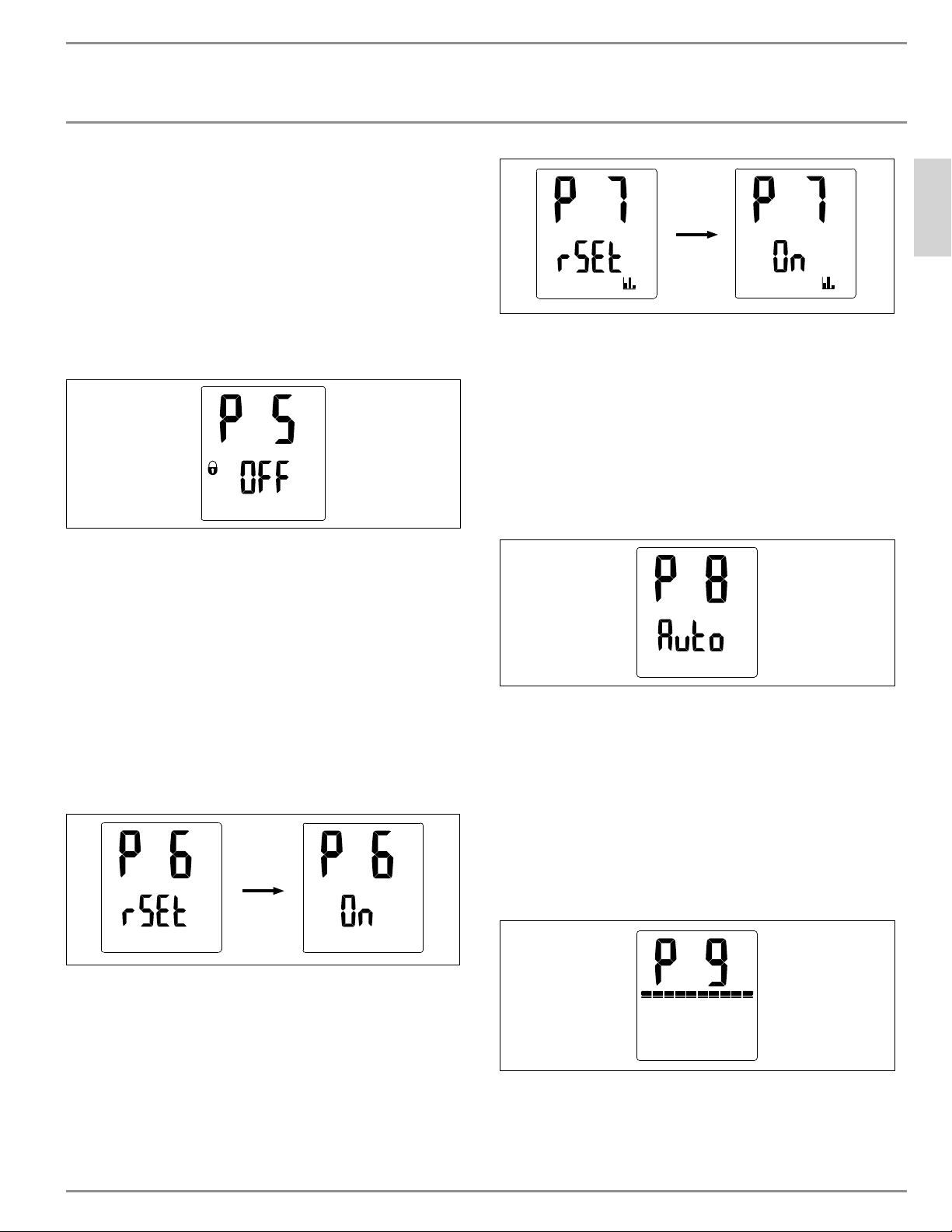
Display-lock parameter setting
The display can be locked to prevent easy alteration of the tempera-
ture setpoint. This menu will flash, indicating that the value can be
changed by rotating the control knob. While “Off” is displayed, the
lock is not active. The lock is active when the display reads “On”.
If the display-lock parameter is set to “On” and the user either holds
the Information button for 5 seconds or lets the display time out for
15 seconds, the display-lock will become active.
With the display-lock active, a lock will appear on the base display,
and no parameters can be changed. In order to disable the lock, hold
the Information button for 12 seconds. The lock will then disappear
and all parameters can be changed again.
Pressing the Information button once while at the display-lock pa-
rameter setting menu will move the display onto the factory setting
reset parameter menu.
Factory setting reset parameter
The temperature setpoint, preset values, temperature, & volume
units can all be reset to their factory settings.
The display will be flashing to indicate that the value can be changed
by rotating the control knob. To reset, first press and hold both
buttons 1 and 2 for 5 seconds, “On” then appears. Then push infor-
mation button for 5 seconds to reset.
Pressing the Information button once will advance the display to the
accumulated savings reset parameter menu.
Accumulated savings reset parameter
Much like the factory setting reset parameter, the calculated accu-
mulated savings value can be reset to zero.
The display will be flashing to indicate that the value can be changed
by rotating the control knob. To reset, first press and hold both
buttons 1 and 2 for 5 seconds, “On” then appears. Then push infor-
mation button for 5 seconds to reset.
Pressing the Information button once will advance the display to the
display backlight time-out parameter.
Display backlight time-out parameter
The backlight of the display can be set to be always on, or set to an
automatic mode that deactivates when no user input is detected for
30 seconds.
The entire display and backlight will be flashing to indicate that the
value can be changed by rotating the control knob. When the value is
set to “On”, the backlight will always be on. When the value is set to
“Auto”, it will automatically deactivate after 30 seconds of inactivity.
Pressing the Information button once while at this menu will advance
the display to the backlight display brightness parameter menu.
Backlight display brightness parameter
The brightness of the display backlight can be adjusted to two differ-
ent parameters. A high and low setting allows for user customization
depending on the light conditions in the installation location.
The power capacity status bar indicates the brightness setting. A
full capacity bar indicates that the brightness is at the high setting.
Two capacity bars indicate that the brightness is at the low setting.
OPERATION
Cleaning, care and maintenance
12 | DHX Trend & DHX Plus www.stiebel-eltron-usa.com
Pressing the Information button once while at this menu will advance
the display back to the T
max
parameter setting page, labeled “P1”.
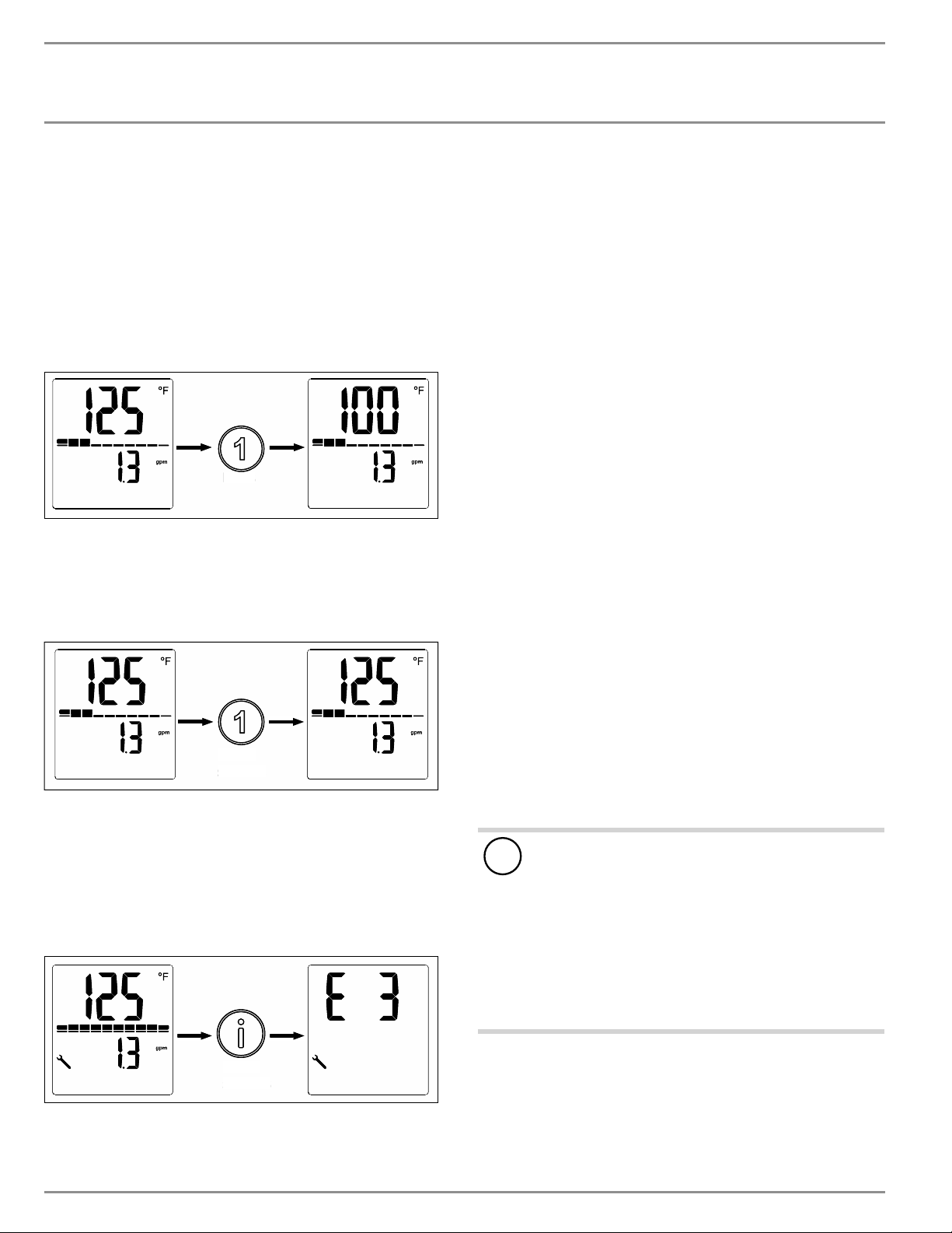
5.5.4 Temperature preset options
DHX Plus models feature two temperature preset settings to allow
for quickly accessible setpoints. Button 1 and Button 2 are capable
of each storing an independent setpoint value.
Changing setpoint to preset values
While the display is at the base display, the user can press either But-
ton 1 or Button 2 to change the setpoint to the buttons stored value.
Press
Pr
es
s
When the button is pressed, the setpoint value will change to what-
ever value was stored up to that point.
Changing the preset values
The preset values can be changed from the default setpoint values.
Hold 3
seconds
Hol
d
3
s
econds
To change the value of either preset 1 or preset 2, first rotate the
control knob to the temperature that you want to set as the preset
value. Then hold the preset button for 3 seconds. The display will
flash to indicate that the preset has been changed successfully.
5.5.5 DHX Plus error menu
If the DHX Plus encounters an error, a wrench will illuminate in the
bottom left of the display.
Hold 5
seconds
H
old
5
s
econ
d
s
While the wrench is showing, press and hold the Information button
for five seconds to advance the display to the error display page.
Consult section 16, “Troubleshooting”, pg. 20, for information on
how to interpret the reported error code.
5.5.6 Returning to the base display
While navigating the display and on any menu other than the base
display, holding the Information button for 5 seconds will return the
display to the base display. Additionally, the display will revert from
a parameter menu to the base display after a 15-second period with
no user input, or from an information menu to the base display after
a 10-second period with no user input.
5.6 Recommended settings
Your electric tankless water heater offers maximum precision and
convenience for DHW production. Should you nonetheless operate
the water heater with a thermostatic valve, we recommend that you:
f Adjust the set temperature on the water heater to over 122 °F
(50 °C). Then set the required set temperature on the thermo-
static valve.
Saving energy
The following recommended settings will result in the lowest energy
consumption:
- 100 °F (38 °C) for hand washbasins, showers, bath
- 131 °F (55 °C) for kitchen sinks
Internal anti-scalding protection (qualified contractors)
If required, the qualified contractor can set a permanent temperature
limit, for example in nurseries, hospitals,etc.
Recommended setting for operation with a thermostatic valve
and water preheated by solar energy
f Set the temperature at the water heater to the maximum
temperature.
Following an interruption to the water supply
!
Material losses
To ensure that the Direct Coil
™
heating system is not dam-
aged following an interruption to the water supply, the
water heater must be restarted by taking the following
steps:
f Disconnect the water heater from the power supply by
turning off the connected circuit breaker.
f Open and close all connected draw-off valves at least 5
times, for at least 3 minutes total, until all air has been
purged from the pipework and the water heater.
f Switch the power back at the circuit breaker back ON.
6. Cleaning, care and maintenance
f Never use abrasive or corrosive cleaning agents. A damp cloth
is sufficient for cleaning the water heater.
f Check the taps regularly. Limescale deposits at the tap outlets
can be removed using commercially available descaling agents.
INSTALLATION
Troubleshooting
ENGLISH
www.stiebel-eltron-usa.com DHX Trend & DHX Plus | 13
7. Troubleshooting
Problem Cause Solution
The water heater will not
start despite the DHW
valve being fully open
There is no power
Check to ensure circuit
breaker in breaker panel
hasn’t tripped. Reset if
necessary
The white AE3 safety
switch has not been
engaged during initial
startup. Activate if neces-
sary (See section 12.2.1,
“Initial AE3 safety switch
activation,” pg. 18). If
the AE3 switch has tripped
after initial installation,
contact a qualified con-
tractor to fix the cause
The aerator in the tap or
the shower head is scaled
up or dirty
Clean and/or descale the
aerator or shower head
The water supply has
been interrupted
Vent the water heater and
the cold water inlet line
When hot water is being
drawn off, cold water
flows for a short period
The air detector detects
air in the water. It switch-
es off the heating output
briefly
The water heater restarts
automatically after 1min-
ute
The required temperature
cannot be set
Internal anti-scalding pro-
tection is active
The internal anti-scalding
protection can only be
adjusted by qualified con-
tractors
If you cannot solve the problem, contact your qualified contractor.
To facilitate and speed up your inquiry, please provide the serial
number from the type plate (000000-0000-000000). For live technical
assistance, please contact us at 800.582.8423. Alternatively, you may
email us at info@stiebel-eltron-usa.com
Nr.: 000000-0000-00000
D0000094552-b
INSTALLATION
8. Safety
Only a qualified contractor should carry out installation, commis-
sioning, maintenance and repair of the water heater.
8.1 General safety instructions
We guarantee trouble-free function and operational reliability only
if original accessories and spare parts intended for the water heater
are used.
!
Material losses
Observe the maximum inlet temperature. Higher tempera-
tures may damage the water heater. You can limit the max-
imum inlet temperature by installing a central thermostatic
valve.
WARNING Electrocution
This water heater contains capacitors which are discharged
when disconnected from the power supply. The capacitor
discharge voltage may briefly exceed60VDC.
8.2 Instructions, standards and regulations
Note
Observe all applicable national and regional regulations
and instructions.
- The electrical resistivity of the water must not fall below that
stated on the type plate. In a linked water network, factor in
the lowest electrical resistivity of the water. Your water supply
utility will advise you of the electrical resistivity or conductivity
of the water in your area.
9. Water heater description
9.1 Standard delivery
The following are delivered with the water heater:
- Filter screen, factory installed in cold water inlet
- Jumper for anti-scalding protection, attached
- Jumper, spare, attached
- 2 x mounting screws
- 2 x wall anchors
- 0.5 gpm (1.9 l/min) flow-reducer/aerator [DHX 3.5-1 Trend
only]. See section 11.3, “Aerator installation at connected fau-
cet,” pg. 16, for more information.
- 1.0 gpm (3.8 l/min) flow-reducer/aerator [DHX 6-2 Trend only].
See section 11.3, “Aerator installation at connected faucet,” pg.
16, for more information.
INSTALLATION
Preparation
14 | DHX Trend & DHX Plus www.stiebel-eltron-usa.com
10. Preparation
10.1 Installation site
!
Material losses
Install the water heater in a room that is free from the risk
of frost.
f Install DHX in a frost free area. If frost may occur, remove the
unit before freezing temperatures set in.
f Always install the water heater vertically with plumbing fittings
pointing downward. Install the water heater near the draw-off
point to minimize pipe runs and thermal losses.
f Taps: Do not use open vented or non-pressurized taps.
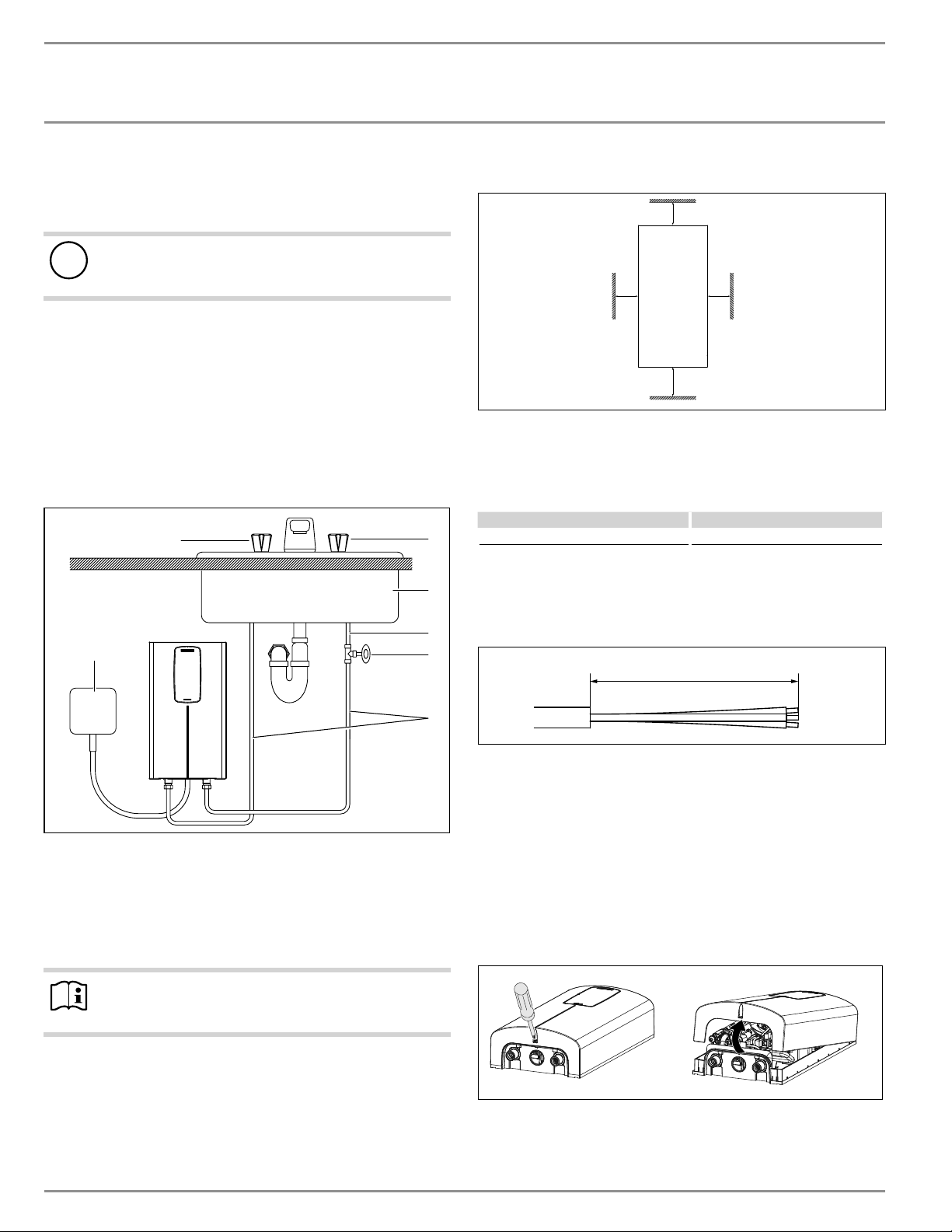
The water heater is suitable for under-sink and over-sink installa-
tion.
Typical under-sink installation
D0000089950-a
6
5
1
3
2
7
4
1 Electrical junction box
2 ½˝ water supply line for faucet installation
3 Shut-off valve
4 Cold water supply
5 Sink
6 Cold valve (right)
7 Hot valve (left)
Note
f Install the water heater flush to the wall. The wall
must have sufficient load bearing capacity.
10.2 Minimum clearances
Ý
Ý
Ý
Ý
D0000079442
f Maintain the minimum clearances to ensure trouble-free oper-
ation of the water heater and facilitate maintenance work.
11. Installation
Factory default settings All DHX Models
Internal temperature limit 140 °F (60 °C)
11.1 Standard wall-mounted installation
11.1.1 Preparing the power cable
4Ǭ–5ǩÝ (125–130 mm)
D0000094559-b
f Prepare the power cable.
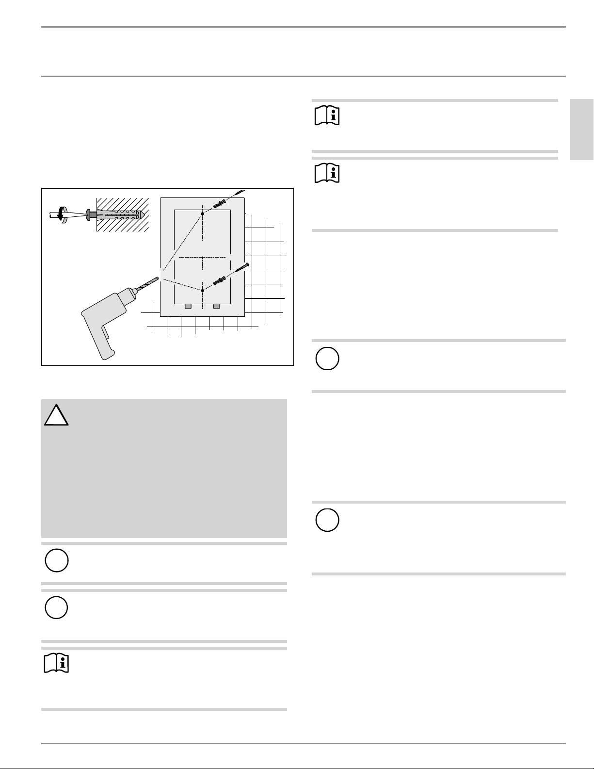
11.1.2 Mounting instructions
f Install DHX as close as possible to the hot water draw-off point,
for example, directly underneath the sink.
f Install DHX in a frost free area. If frost may occur, remove unit
before freezing temperatures set in.
f Observe minimum clearances on all sides to ensure unobstruct-
ed servicing if necessary.
f Remove plastic cover by loosening the screw on the bottom.
Lift cover off from the bottom.
D0000094555-b
f Mark the 2drill holes, referencing their position using the
water heater rear panel as a guide.
f Set water heater rear panel aside and drill the 2 marked holes.
INSTALLATION
Installation
ENGLISH
www.stiebel-eltron-usa.com DHX Trend & DHX Plus | 15
f Install wall anchors in the wall, then insert and tighten each
mounting screw partially. Screws and plastic wall anchors for
mounting on drywall or wood are provided.
f Hang the unit on the 2 mounting screws, ensuring the rear of
the unit is flush against the wall.
f Once the unit is in position, mount the unit securely to the wall
by fully tightening the 2 mounting screws.
D0000089951-a
11.2 Water connections
!
CAUTION: DO NOT INSTALL IN A BATH ENCLOSURE OR
SHOWER STALL OR CONNECT TO A SALT-REGENERATED
WATER SOFTENER OR A WATER SUPPLY OF SALT
WATER
FOR USE ON AN INDIVIDUAL BRANCH CIRCUIT ONLY
CAUTION: CONNECT ONLY TO A CIRCUIT PROTECTED BY A
CLASS A GROUND FAULT CIRCUIT INTERRUPTER
USE COPPER CONDUCTORS ONLY
USE BONDING CONDUCTOR IN ACCORDANCE WITH THE
CANADIAN ELECTRICAL CODE, PART I
!
Material losses
Carry out all water connection and installation work in
accordance with regulations.
!
Material losses
Excessive heat from soldering on copper pipes near the
DHX may cause damage to the unit or the plastic filter
screen located in the cold water inlet.
NOTICE
The cold water connection to the unit MUST be discon-
nected periodically in order to clean the filter screen.
It is required to use water connections that are easily
detachable such as braided steel flex connectors.
NOTICE
Hard water or water with a high mineral count may dam-
age the unit. Damage to the unit caused by scale or a high
mineral count is not covered under the warranty.
NOTICE
Tankless water heaters such as the DHX Trend are not
required to be equipped with a temperature and pressure
relief valve (T&P). If the local inspector will not pass the
installation without a T&P, it should be installed on the
hot water outlet side of the unit.
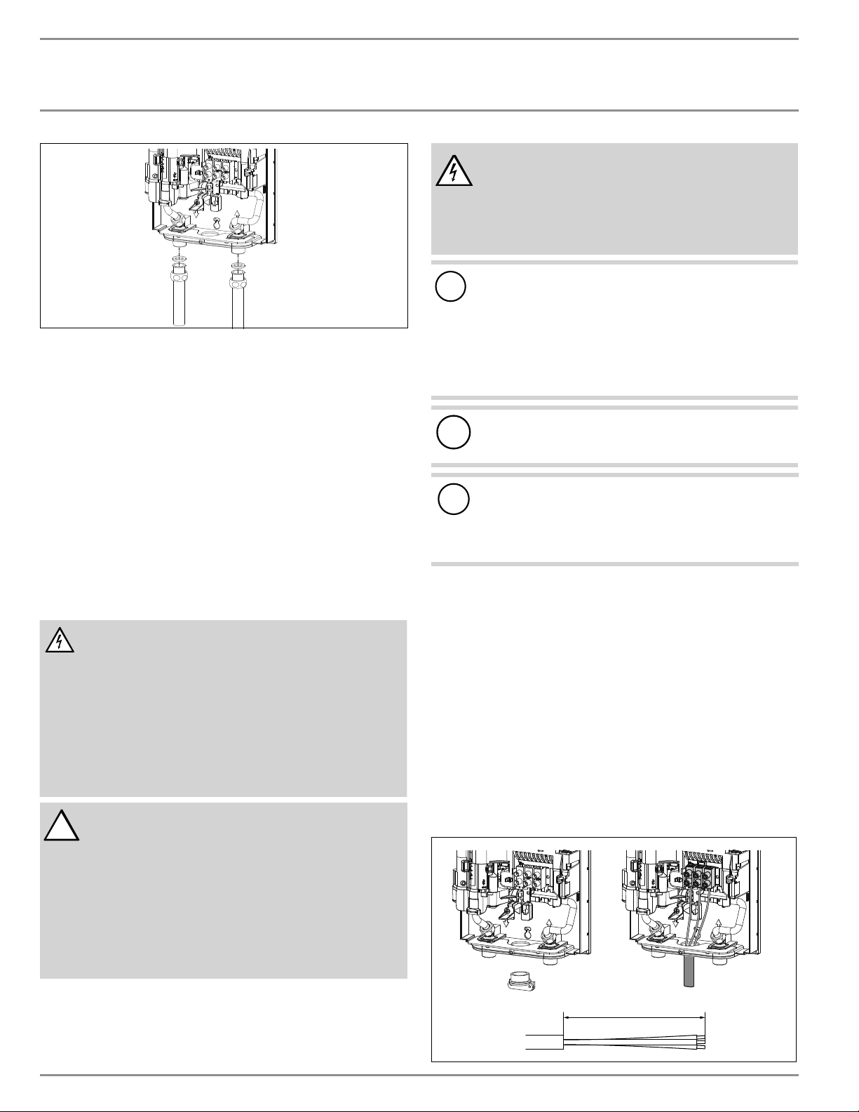
11.2.1 Permissible water connection materials
f The DHX’s hot water outlet (left) is designed for connection to
copper tubing, PEX tubing or a braided stainless steel hose
with a ½˝ NPT female tapered thread.
f The plumbing on the cold water inlet side (right) needs to be
such that it can easily be removed to allow access to the inlet
filter screen. The easiest way to achieve this is to use a braided
steel flex connector with a ½˝ female NPT connection.
!
Material losses
If plastic pipework systems are used, take into account the
maximum inlet temperature and the maximum permissible
pressure.
11.2.2 Flow rate
f Ensure that the minimum activation flow rate for switching on
the water heater is met: 0.264 gal (1.0 l/min).
f If the required minimum activation flow rate is not met when
the draw-off valve is fully opened, increase the water line pres-
sure. Minimum supply pressure is 26.1 psi (1.8 bar).
11.2.3 Water connection instructions
!
Material losses
If soldering near the unit is necessary, please direct the
flame away from the housing of the unit in order to avoid
damage. Note that excessive heat from soldering (not rec-
ommended) near the cold water inlet fitting may damage
the plastic filter screen located inside it.
All plumbing work must comply with national and applicable state
and local plumbing codes.
Cold water connection (inlet) is on the right side of the unit, hot
water connection (outlet) is on the left side of unit.
f A pressure reducing valve must be installed if the cold water
supply pressure exceeds 150 psi (10 bar).
f Make certain that the cold water supply line has been flushed
to remove any scale and dirt.
f Install shut-off valve in cold water line as shown in the illus-
tration on page 14. This allows the unit to be easily isolated for
maintenance purposes.
INSTALLATION
Installation
16 | DHX Trend & DHX Plus www.stiebel-eltron-usa.com
D0000094555-b
f Connected braided steel flex connectors (recommended for hot
outlet, required for cold inlet, not supplied) to the twin ½˝ NPT
male connectors.
f Open the shut-off valve in the cold water inlet line.
When all plumbing work is completed, check for leaks and take
corrective action before proceeding.
11.3 Aerator installation at connected faucet
DHX 3.5-1 Trend ships with a 0.5 gpm (1.9 l/min) pressure compen-
sating flow-reducer/aerator. DHX 6-2 Trend ships with a 1.0 gpm
(3.8 l/min) pressure compensating flow-reducer/aerator. For these
models, the aerator must be installed on the faucet the water heater
is connected to. Failure to install the aerator may result in lower
water temperatures than desired.
11.4 Electrical connection
WARNING: Electrocution
Before beginning any work on the electric installation,
be sure that main breaker panel switches are “Off” to
avoid any danger of electric shock. All mounting and
plumbing must be completed before proceeding with
electrical hook-up.
The unit must be properly grounded in accordance with
state and local codes, or in absence of such codes, in
accordance with national electric code or the Canadian
electric code. Failure to electrically ground the product
could result in serious personal injury or death.
!
CAUTION: DO NOT INSTALL IN A BATH ENCLOSURE
OR SHOWER STALL. DO NOT CONNECT TO A
SALT-REGENERATED WATER SOFTENER OR A WATER
SUPPLY OF SALT WATER.
FOR USE ON AN INDIVIDUAL BRANCH CIRCUIT ONLY.
CAUTION: CONNECT ONLY TO A CIRCUIT PROTECTED BY A
CLASS A GROUND FAULT INTERRUPTER
USE BONDING CONDUCTOR IN ACCORDANCE WITH THE CA-
NADIAN ELECTRICAL CODE, PART I
WARNING Electrocution
The connection to the power supply is only permissible as
a permanent connection in conjunction with a ¾˝ Romex
clamp. Ensure the water heater can be separated from
the power supply by an isolator that disconnects all poles
with at least 1/8˝ (3mm) contact separation.
!
Supply this appliance only from a grounded system. A
green terminal (or a wire connector marked “G”, “GR”,
“GROUND”, OR “GROUNDING”) is provided for wiring the
appliance. To reduce the risk of electric shock, connect
this terminal or connector to the grounding terminal of
the electric service or supply panel with a continuous
copper wire in accordance with the electrical installation
code.
!
Material losses
Observe the type plate. The specified rated voltage must
match the supply line voltage.
!
Material losses
The DHX 3.5-1 Trend must only be connected to a 120V elec-
trical supply. Connecting the DHX 3.5-1 Trend to a 208–240V
electrical supply will permanently damage the unit and void
the factory warranty.
f All electrical work must comply with national and applicable
state and local electrical codes.
f The DHX should be connected to a properly grounded dedicat-
ed branch circuit of proper voltage rating. In installa tions with
several DHX units, each unit requires an independent circuit.
Please refer to the technical data table for the correct wire and
circuit breaker size.
f A 3/4˝ Romex clamp (required, not supplied) should be in-
stalled in the opening located between the hot and cold water
connections. The wire should be fed through the Romex clamp.
The “live” wires must be connected to the slots on the terminal
block marked N and L (DHX 3.5-1 Trend only) or L and L (all
other versions). The ground wire must be connected to the slot
marked with the ground symbol. See section 17.2, “Wiring dia-
grams,” pg. 21.
4Ǭ–5ǩÝ (125–130 mm)
D0000089948-a
INSTALLATION
Commissioning
ENGLISH
www.stiebel-eltron-usa.com DHX Trend & DHX Plus | 17
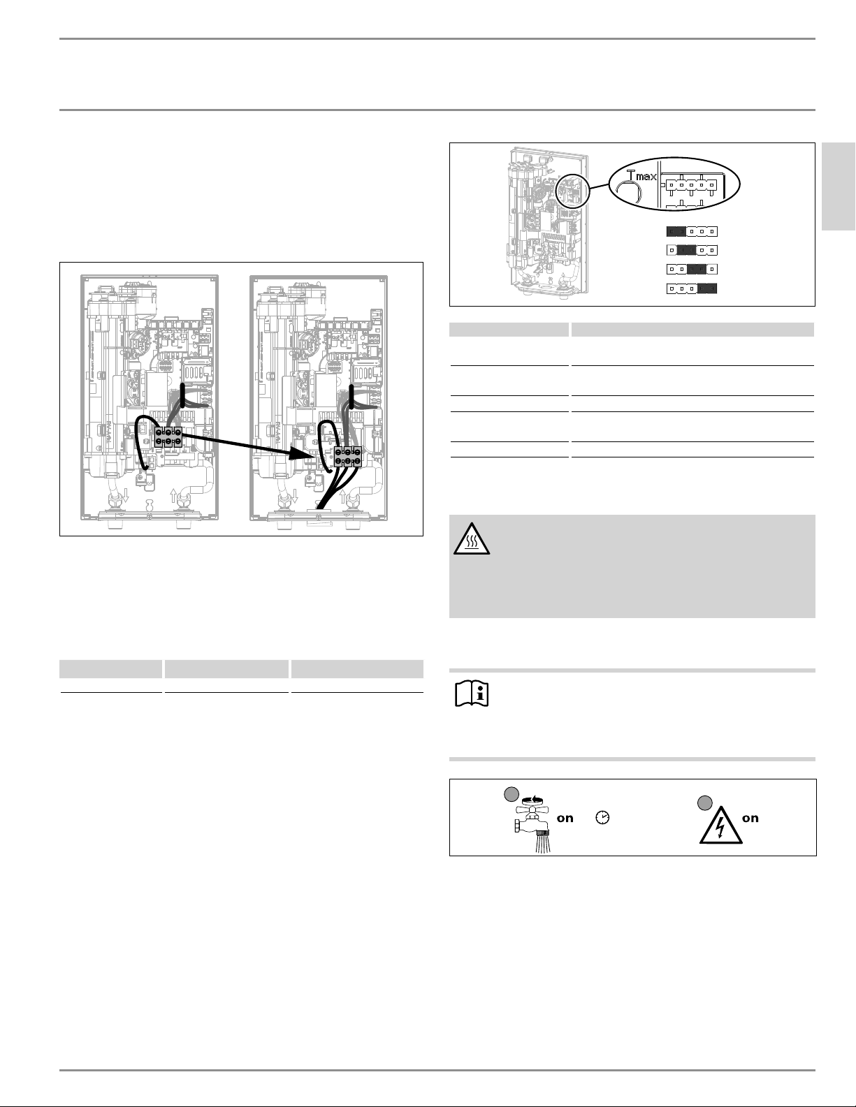
11.5 Electrical connection with short power cable
If the power cable is not quite long enough, you can install the wiring
block closer to the aperture in the water heater.
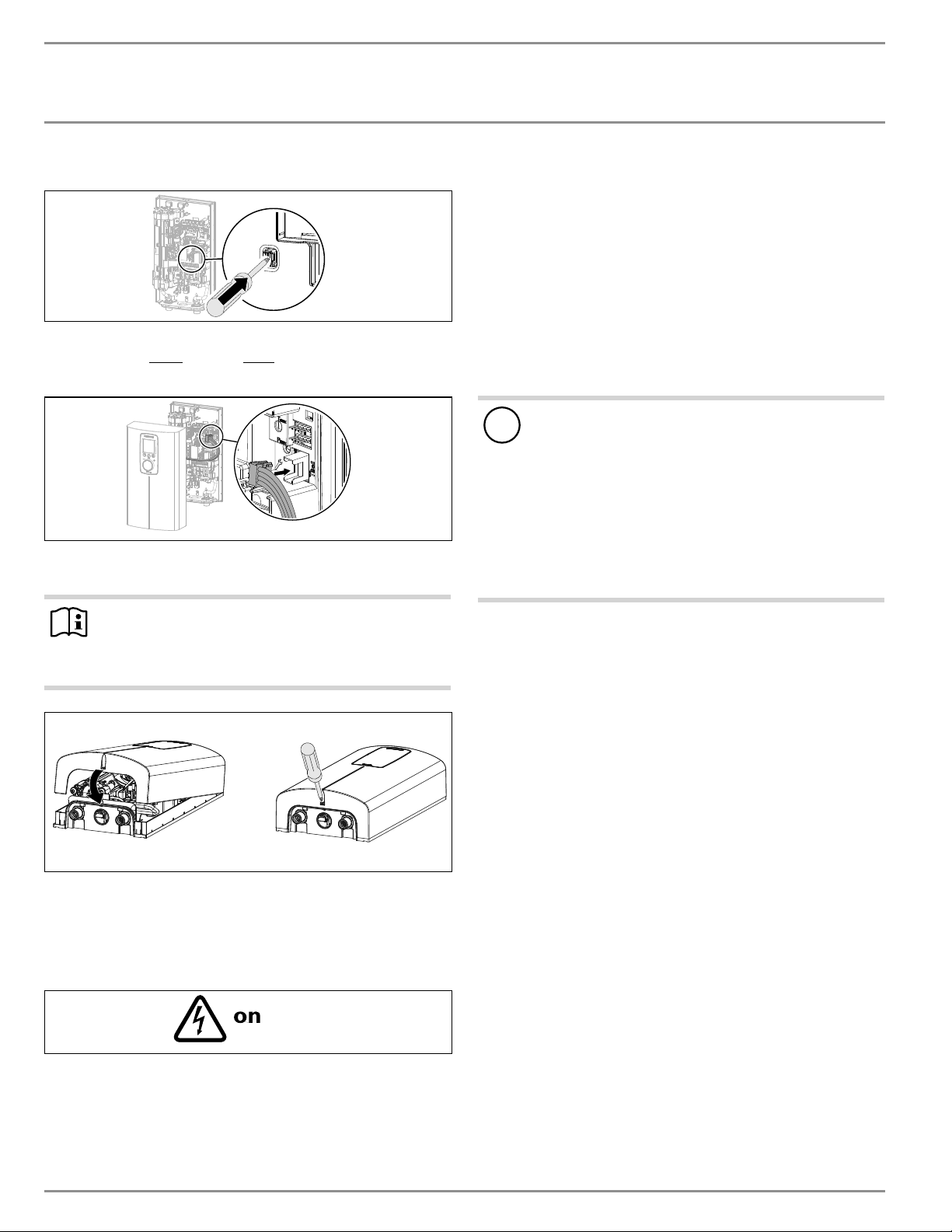
f Reposition the wiring block from the top to the bottom. To do
so, unclip the wiring block by pushing it firmly to the left and
pulling it forwards.
D0000095302-b
f Clip the wiring block in at the bottom by pushing it inwards
and to the left until it clicks into place.
11.6 Wiring block
Consult the chart below for the recommended torque amounts on
the wiring block screws.
Screw Size (mm) Min. Torque (N•cm) Min. Torque (lbf•in)
M6 200-250 17.7–22.1
Using the proper torque specifications to secure wire to the wiring
block helps to avoid personal loss or property damage.
12. Commissioning
12.1 Internal anti-scalding protection via jumper slot
For increased safety, the qualified contractor can set an internal an-
ti-scalding temperature limit via the “T
max
” jumper. The anti-scald-
ing protection feature limits the maximum output temperature of
the water heater. This feature overrides the temperature adjust-
ment display on the front cover (both the temperature selection
and temperature limit via software functions). A user can still make
temperature adjustments below the anti-scalding limit using the
display, however, any temperature selected that is higher than the
Tmax limit set will be ignored, and the output temperature will be
limited to the T
max
value.
38°C | 100°F
43°C | 109°F
50°C | 122°F
60°C | 140°F
D0000094558-b
Jumper position Description
38 °C | 100 °F Code-compliant hand washing applications (fac-
tory default setting)
43 °C | 109 °F Applications where risk of scalding may be a
concern
50 °C | 122 °F DHW for kitchen sink, utility sink, etc.
60 °C | 140 °F Commercial applications (kitchens, etc.), health
code requirements
No jumper Limit 38 °C | 100 °F
f Install the jumper in the required position on the “T
max
” pin
strip.
CAUTION Burns
If the water supplied to the water heater is preheated, the
internal anti-scalding protection and the user-adjustable
temperature limit may be exceeded.
In such cases, limit the temperature with an upstream
central thermostatic valve.
12.2 Initial start-up
Note
During initial start-up, you MUST engage the AE3 safety
switch by depressing the white reset button before supply-
ing power to the water heater. The unit will NOT operate
until the safety switch has been engaged.
PLQ
1
2
D0000053277
f Open and close all connected draw-off valves at least five times
total. Let water run for at least three minutes, until all air has
been purged from the pipework and the water heater.
f Ensure there are no water leaks from any plumbing
connections.
INSTALLATION
Water heater shutdown
18 | DHX Trend & DHX Plus www.stiebel-eltron-usa.com
12.2.1 Initial AE3 safety switch activation
D0000094561-b
f Engage the AE3 safety switch by firmly pressing the white reset
button until it clicks and fully locks in place (the water heater is
delivered with the safety switch disengaged).
D0000082937
f Connect the programming unit connecting cable plug to the
PCB.
Note
It is essential to plug the connecting cable from the pro-
gramming unit into the PCB before switching on the power.
Otherwise, the programming unit will not function.
D0000073642
f Hook the water heater cover into the water heater back panel
at the top rear. Pivot the cover downwards. Check that the cover
is securely seated at both top and bottom.
f Secure the cover with the screw.
f Remove the protective film from the front panel.
D0000053281
f Switch on the power supply.
f Ensure the programming unit is functioning correctly.
12.2.2 Water heater handover
f Explain the water heater functions to users, and familiarize
them with how it works.
f Make the user aware of potential dangers, especially the risk of
scalding.
f Hand over the instructions.
12.3 Operation with preheated water
The maximum inlet temperature may be limited by installing a
central thermostatic valve. Use the thermostatic valve for central
premixing, for example when operating an tankless water heater
with preheated water. For use in shower operation, the valve must
be set to a maximum of 131 °F (55 °C).
12.4 Recommissioning
!
Material losses
To ensure that the Direct Coil
™
heating system is not dam-
aged following an interruption to the water supply, the
water heater must be restarted by taking the following
steps:
f Disconnect the water heater from the power supply by
turning the connected circuit breaker.
f Open and close all connected draw-off valves at least 5
times, for at least 3 minutes total, until all air has been
purged from the pipework and the water heater.
f Switch the power back ON.
13. Water heater shutdown
f Turn the connected circuit breaker too the “Off” position.
f Drain the water heater (See section 15.1, “Draining the water
heater,” pg. 19").
INSTALLATION
Service information
ENGLISH
www.stiebel-eltron-usa.com DHX Trend & DHX Plus | 19
14. Service information
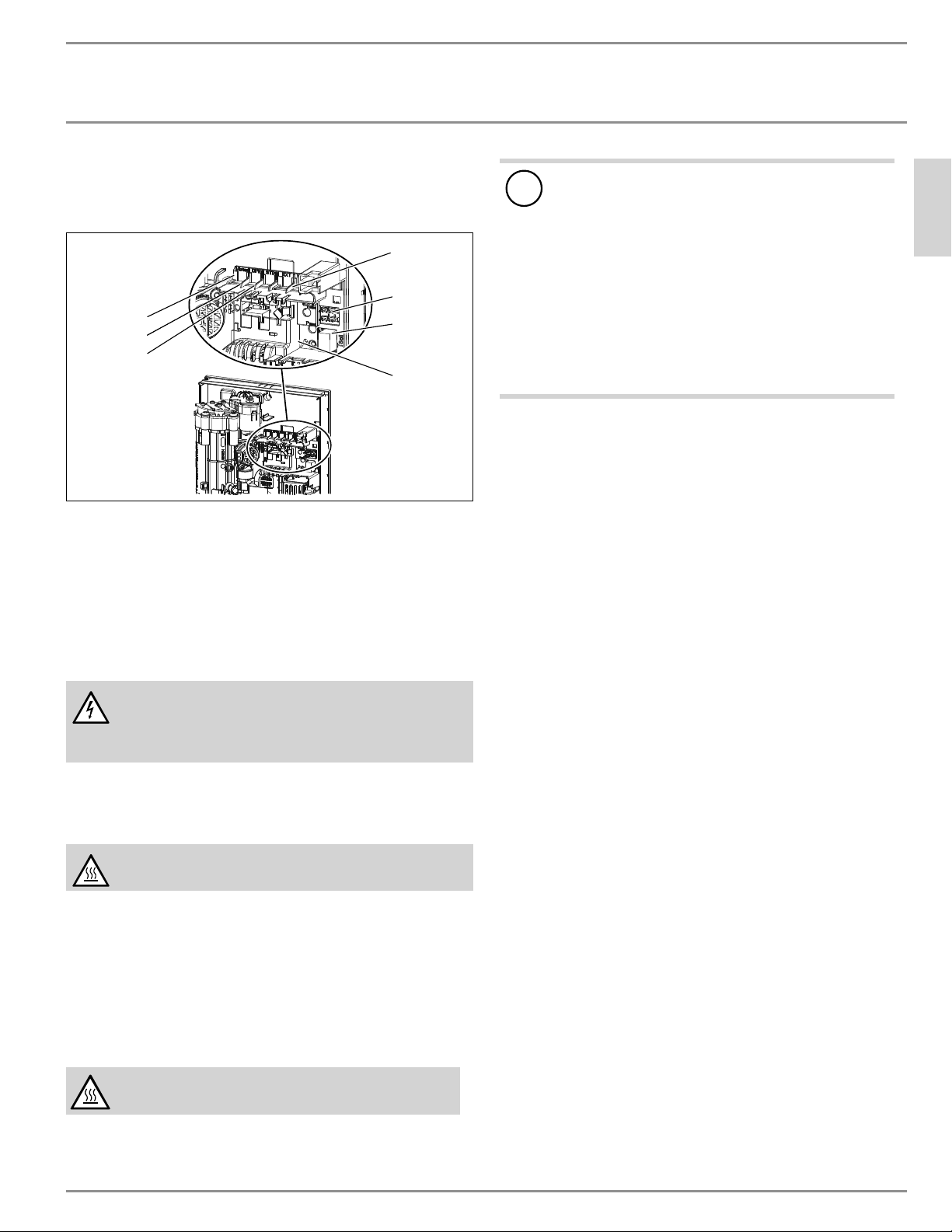
Connection overview/component overview
1
2
3
5
6
7
4
D0000095301-a
1 Motorized valve
2 Flow sensor
3 High limit safety cut-out, automatic reset, klixon
4 NTC sensor
5 Pin strips for connected load and anti-scalding protection
6 Programming unit plug-in position
7 Diagnostic traffic lights
15. Maintenance
WARNING Electrocution
Before beginning any work on the water heater, be sure
that main breaker panel switches are “Off” to avoid any
danger of electric shock.
15.1 Draining the water heater
The water heater can be drained for maintenance work.
WARNING Burns
Hot water may escape when you drain the water heater.
f Close the shut-off valve in the cold water inlet line.
f Open all draw-off valves.
f Undo the water connections on the water heater.
f Store the dismantled water heater free from the risk of frost,
as water residues remaining inside the water heater can freeze
and cause damage.
15.2 Cleaning the filter screen
WARNING Burns
Hot water may escape when you drain the appliance.
!
Material losses
To ensure that the Direct Coil
™
heating system is not dam-
aged following an interruption to the water supply, the
water heater must be restarted by taking the following
steps:
f Shut off power to the unit at the breaker panel by
making sure that connected circuit breakers are
“OFF” to avoid any danger of electric shock.
f Open and close all connected draw-off valves at
least 5 times, for at least 3 minutes total, until all air
has been purged from the pipework and the water
heater.
f Switch the power back ON at the breaker panel.
The DHX has a built in sediment filter screen that should be cleaned
periodically:
f Turn off power to the water heater at the circuit breaker.
f Turn off the water supply to the water heater at the shut-off
valve.
f Open a connected hot water tap to relieve built-up pressure
(this will minimize leakage when removing the connection from
the cold water inlet).
f Disconnect the braided steel flex connector from the cold water
inlet fitting (right).
f To remove the filter screen from the bottom of the cold water
inlet, carefully insert a flathead screwdriver just above the
plastic lip of the filter screen, and gently pull downward.
f Clean the filter screen, re-insert securely into the cold water
inlet fitting, and reconnect the braid steel flex connector to the
cold water inlet.
f Open the cold water supply shut-off valve.
f Vent the air from pipes and the water heater by opening and
closing all connected draw-off valves at least 5 times, for at
least 3 minutes total, until all air has been purged from the
pipework and the water heater.
f Turn on circuit breaker to bring electrical power to the unit.
INSTALLATION
Troubleshooting
20 | DHX Trend & DHX Plus www.stiebel-eltron-usa.com
16. Troubleshooting
WARNING Electrocution
Never remove or reinstall the water heater’s cover
unless the electricity servicing the unit is turned off.
Failure to do so could result in personal injury or death.
WARNING Electrocution
To test the water heater using the internal diagnostic
lights, it must be connected to the power supply.
When testing with the cover off, never touch any part
of the water heater. Doing so could result in serious
personal injury or death.
Note
When testing the water heater using the diagnostic lights,
water must be flowing through the unit.
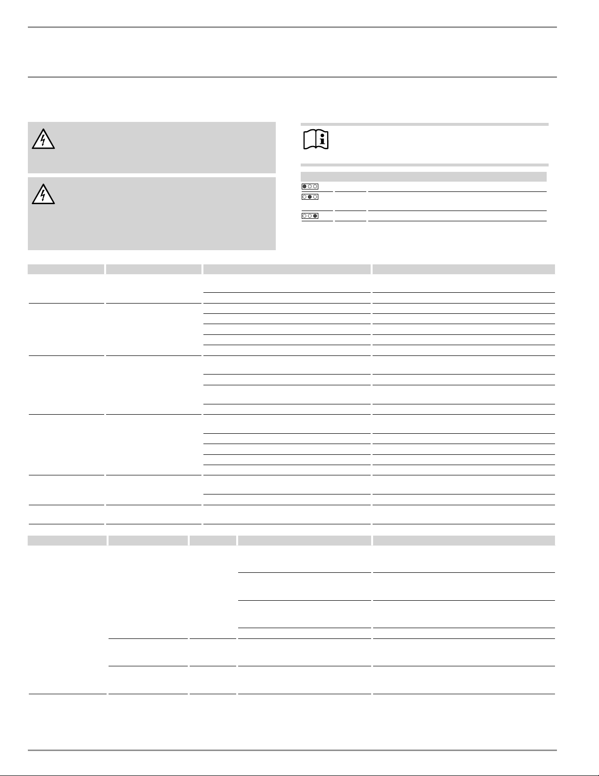
Diagnostic lights
Red Lights up in the event of an error
Yellow Lights up in heating mode/flashes when output limit
reached
Green Flashing: Water heater connected to power supply
Diagnostic lights Problem Cause Solution
No LED is lit The water heater does not
heat up
There is no power Check to ensure the connected circuit breaker in the main
breaker panel hasn’t tripped. Reset if necessary
The PCB is faulty Replace the PCB
Green flashing, yellow
off, red off
No DHW
The shower head/aerator is scaled up Descale or replace the shower head/aerators if necessary
The filter screen in the cold water inlet is dirty Clean the filter screen
The flow sensor is not plugged in Connect the cable to the PCB
The flow sensor is faulty Replace the flow sensor
The PCB is faulty Replace the PCB
Green flashing, yellow
on, red off
The display on the program-
ming unit is off
There is a loose cable between the PCB and the pro-
gramming unit
Check the cable and plug the cable into the programming
unit and/or PCB
The cable of the programming unit is faulty Check the cable and replace if necessary
The programming unit PCB is faulty Replace the programming unit, only available with a new
heater cover
The PCB is faulty Replace the PCB
Green flashing, yellow
on, red off
The outlet temperature does
not match the set value
The programming unit was not plugged in before
power was switched on
Perform a reset by switching off the power to the water
heater
The outlet sensor is faulty Replace the outlet sensor
The tap is faulty Replace the tap
The heating system is faulty Replace the heating system
The PCB is faulty Replace the PCB
Plus models only:
Green flashing, yellow
The outlet temperature does
not match the set value
Motorized valve limit reached Reduce the set temperature
flashing, red off Motorized valve is faulty Replace the motorized valve
Green flashing, yellow
off, red on
No DHW Air detected Continue draw-off for >1 minute
Diagnostic lights Display readout Problem Cause Solution
Plus models only:
Green flashing, yellow
off, red on
Wrench flashes (displays
E1 and wrench in menu
“Fault code display”)
No DHW
AE3 safety switch not activated during
commissioning
Activate AE3 safety switch by pressing the reset button
firmly. See section 12.2.1, “Initial AE3 safety switch acti-
vation,” pg. 18
AE3 safety switch triggered by
self-resetting high limit safety cut-out
Klixon
Check high limit safety cut-out, Klixon (plug-in connec-
tion, connecting cable); activate AE3 safety switch
AE3 safety switch responds again after
high limit safety cut-out Klixon has been
checked; high limit safety cut-out faulty
Replace high limit safety cut-out Klixon activate AE3 safe-
ty switch and draw off water at the maximum set value
for >1 min
Safety switch responds again; PCB faulty Replace the PCB
Wrench flashes (displays
E2 and wrench in menu
“Fault code display”)
No DHW
PCB faulty (lead break or short circuit in
inlet sensor)
Replace the PCB
Wrench flashes (displays
E3 and wrench in menu
“Fault code display”)
No DHW
Short circuit in outlet sensor
Check the outlet sensor, replace if necessary
INSTALLATION
ZĤ¼êÐ|ŒêĒĉ
ENGLISH
www.stiebel-eltron-usa.com DHX Trend & DHX Plus | 21
17. Specification
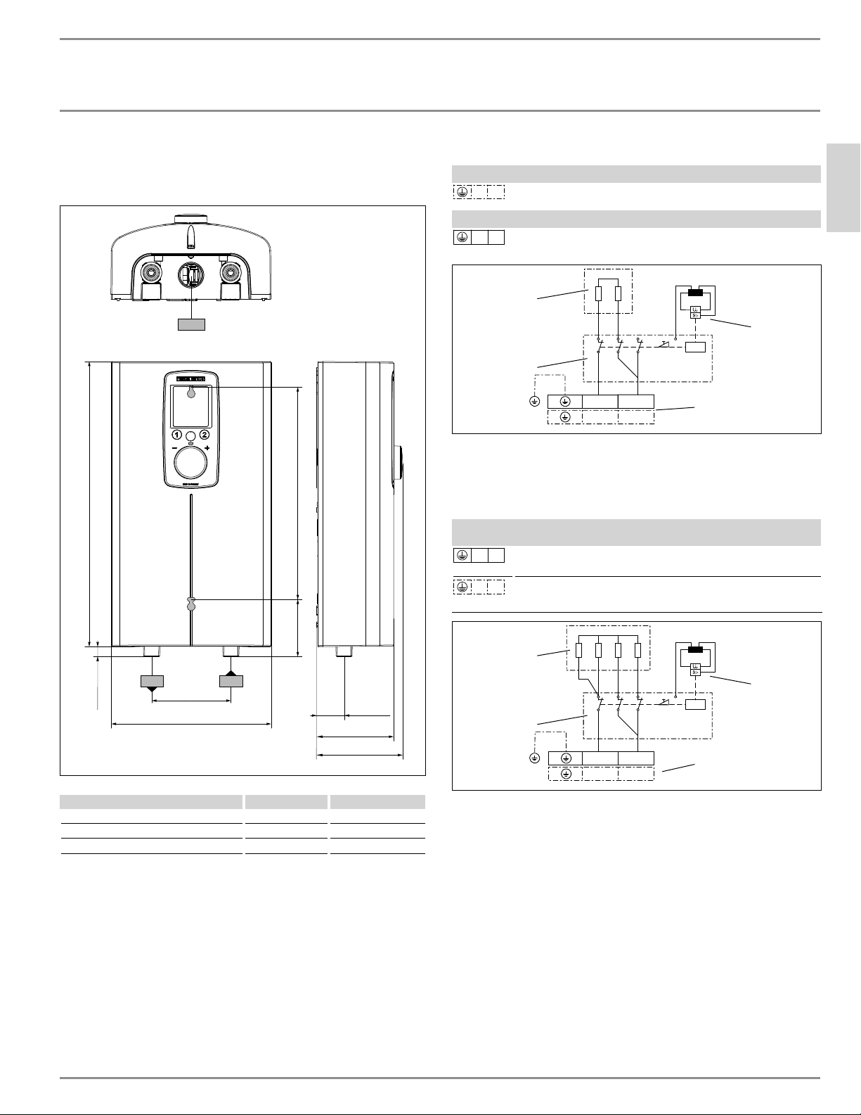
17.1 Dimensions and connections
c06 c01
c01
c06
b01
i
7
15
/
16
Ý (202)
1
3
/
8
Ý (35)
4
5
/
16
Ý(109)
1
9
/
16
Ý (40)
3
7
/
8
Ý (98)
14
3
/
16
Ý (360)
Mounting holes, rear cover
12
5
/
8
Ý (320)
½Ý (13)
3
15
/
16
Ý (100)
D0000094547-b
DHX
b02 Entry electrical cables I Finished walls
c01 Cold water inlet Male thread ½˝ NPT
c06 DHW outlet Male thread ½˝ NPT
17.2 Wiring diagrams
DHX 3.5-1 Trend
L N
1/N/GND ~ 120 V
DHX 6-2 Trend
L L
2/GND ~ 208 / 240 V
N
L
L
L
D0000085463
1
3
4
2
1 Power PCB with integral safety switch
2 Direct Coil
™
heating system
3 Self-resetting high limit safety cut-out, Klixon
4 Wiring block
DHX 8-2 Trend | DHX 10-2 Trend | DHX 12-2 Trend & Plus
DHX 15-2 Trend & Plus
L L
2/GND ~ 208 / 240V
L N
1/N/GND ~ 208 / 240V
N
L
L
L
D0000077991
1
3
4
2
1 Power PCB with integral safety switch
2 Direct Coil
™
heating system
3 Self-resetting high limit safety cut-out, Klixon
4 Wiring block
INSTALLATION
ZĤ¼êÐ|ŒêĒĉ
22 | DHX Trend & DHX Plus www.stiebel-eltron-usa.com
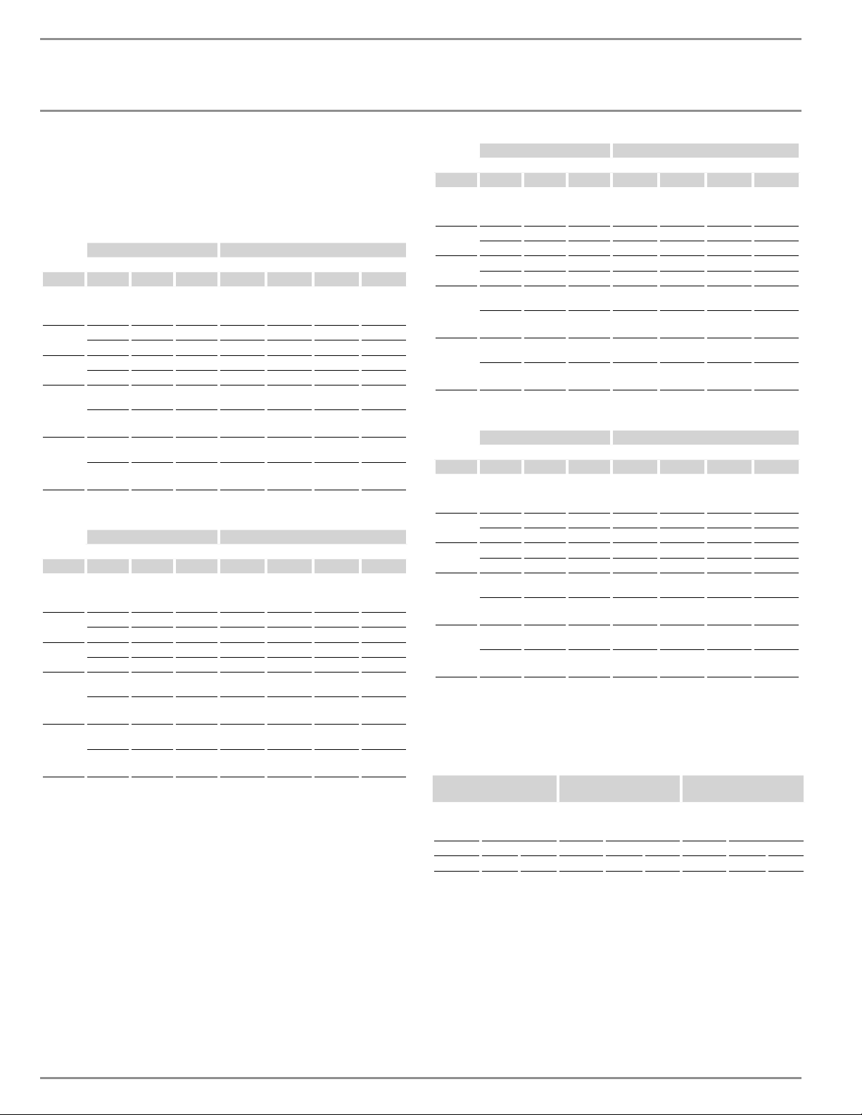
17.3 Hot water output
The domestic hot water (DHW) output is subject to the connected
power supply, and the cold water inlet temperature. The rated volt-
age and rated output can be found on the type plate.
Power output in kW 100 °F DHW output in gpm
Rated voltage Cold water inlet temperature
Model ĜŝƃŨp ŝƃÄŨp ŝÔƃŨp 41 °F 50 °F 59 °F 68 °F
DHX
3.5-1
Trend 3.5 0.41 0.48 0.58 0.75
DHX 8-2
Trend
5.4 0.63 0.74 0.9 1.15
7.2 0.83 0.98 1.2 1.54
DHX 10-2
Trend
7.2 0.83 0.98 1.2 1.54
9.6 1.11 1.31 1.6 2.05
DHX 12-2
Trend &
Plus
9.0 1.04 1.23 1.5 1.92
12.0 1.39 1.64 2.0 2.56
DHX 15-2
Trend &
Plus
10.8 1.24 1.46 1.78 2.28
14.4 1.67 1.97 2.4 3.07
Power output in kW 122 °F DHW output in gpm
Rated voltage Cold water inlet temperature
Model ĜŝƃŨp ŝƃÄŨp ŝÔƃŨp 41 °F 50 °F 59 °F 68 °F
DHX
3.5-1
Trend 3.5 0.3 0.33 0.38 0.44
DHX 8-2
Trend
5.4 0.46 0.51 0.59 0.68
7.2 0.61 0.68 0.78 0.91
DHX 10-2
Trend
7.2 0.61 0.68 0.78 0.91
9.6 0.81 0.91 1.04 1.21
DHX 12-2
Trend &
Plus
9.0 0.76 0.85 0.98 1.14
12.0 1.01 1.14 1.3 1.52
DHX 15-2
Trend &
Plus
10.8 0.9 1.02 1.16 1.35
14.4 1.21 1.37 1.56 1.82
Power output in kW 38 °C DHW output in l/min
Rated voltage Cold water inlet temperature
Model ĜŝƃŨp ŝƃÄŨp ŝÔƃŨp 5 °C 10 °C 15 °C 20 °C
DHX
3.5-1
Trend 3.5 1.5 1.8 2.2 2.8
DHX 8-2
Trend
5.4 2.3 2.8 3.4 4.3
7.2 3.1 3.7 4.5 5.7
DHX 10-2
Trend
7.2 3.1 3.7 4.5 5.7
9.6 4.2 4.9 6.0 7.6
DHX 12-2
Trend &
Plus
9.0 3.9 4.6 5.6 7.1
12.0 5.2 6.1 7.5 9.5
DHX 15-2
Trend &
Plus
10.8 4.6 5.5 6.6 8.5
14.4 6.2 7.3 8.9 11.4
Power output in kW 50 °C DHW output in l/min
Rated voltage Cold water inlet temperature
Model ĜŝƃŨp ŝƃÄŨp ŝÔƃŨp 5 °C 10 °C 15 °C 20 °C
DHX
3.5-1
Trend 3.5 1.1 1.3 1.4 1.7
DHX 8-2
Trend
5.4 1.7 1.9 2.2 2.6
7.2 2.3 2.6 2.9 3.4
DHX 10-2
Trend
7.2 2.3 2.6 2.9 3.4
9.6 3.0 3.4 3.9 4.6
DHX 12-2
Trend &
Plus
9.0 2.9 3.2 3.7 4.3
12.0 3.8 4.3 4.9 5.7
DHX 15-2
Trend &
Plus
10.8 3.4 3.8 4.4 5.1
14.4 4.6 5.1 5.9 6.9
17.4 Application areas/conversion table
Here data is shown for electrical resistivity and electrical conduc-
tivity.
Standard specifica-
ŒêĒĉ|ŒĜÑŨ³
ŝƃŨ³
ŝÑŨ³
Min.
resistivity
ρ≥
Max.
conductivity ı≤
Min.
resistivity
ρ≥
Max.
conductivity ı≤
Min.
resistivity
ρ≥
Max.
conductivity ı≤
Ωcm mS/m μS/cm Ωcm mS/m μS/cm Ωcm mS/m μS/cm
1100 91 910 970 103 1031 895 112 1117
17.4.1 Sizing the pipework
When calculating the size of the pipework, an water heater pressure
drop of 14.5 psi (0.1MPa) is recommended.
17.5 Fault conditions
In the event of a fault, temperatures up to 176 °F (80 °C) at a pressure
of 145 psi (1.0 MPa) can occur briefly in the installation.
INSTALLATION
ZĤ¼êÐ|ŒêĒĉ
ENGLISH
www.stiebel-eltron-usa.com DHX Trend & DHX Plus | 23
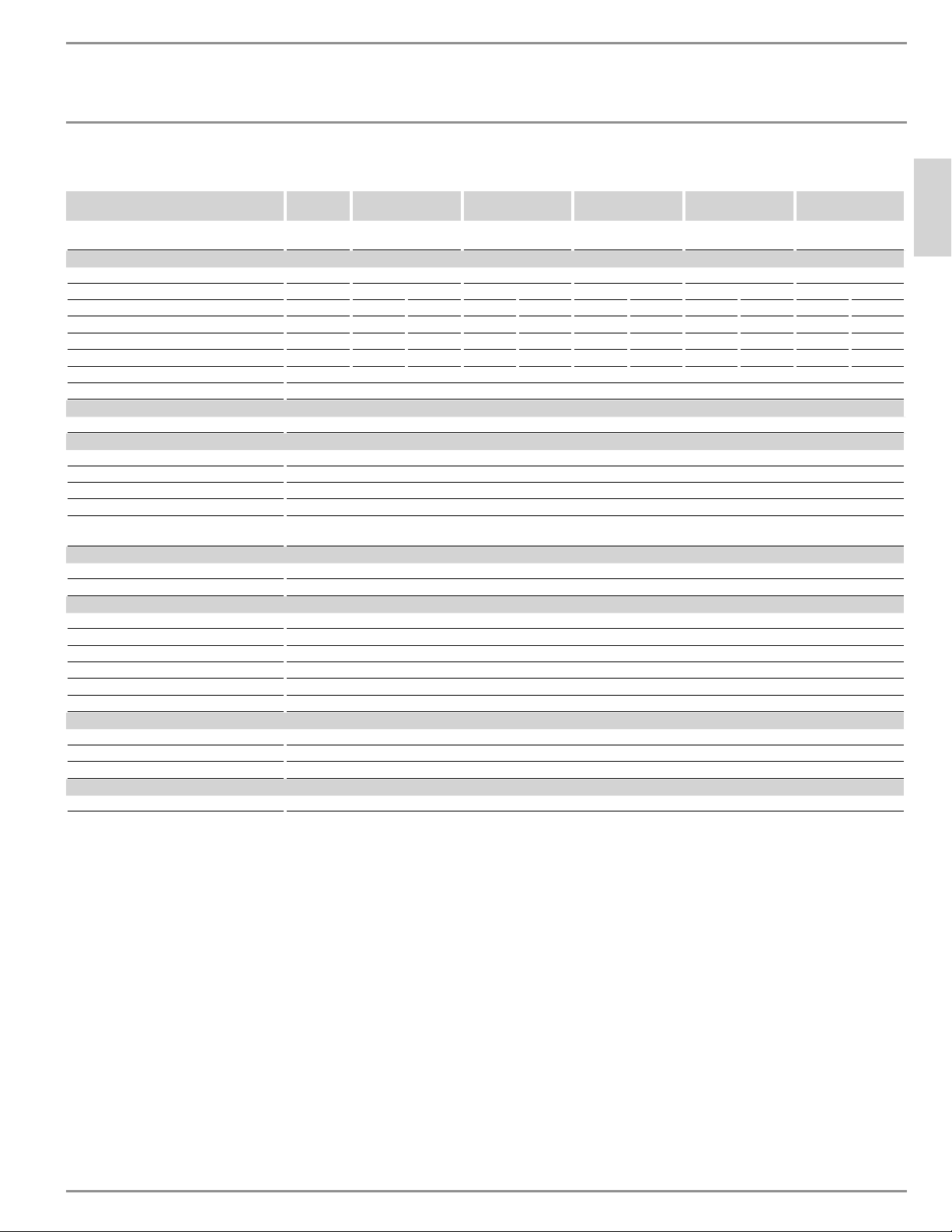
17.6 Data table
DHX 3.5-1
Trend
DHX 6-2 Trend DHX 8-2 Trend DHX 10-2 Trend DHX 12-2 Trend
DHX 12-2 Plus
DHX 15-2 Trend
DHX 15-2 Plus
Item no. 200067 203795 200068 200069 200070 (Trend)
200066 (Plus)
200071 (Trend)
202151 (Plus)
Electrical data
Phase (50/60 Hz) 1/N/GND 1/N/GND | 2/GND 1/N/GND | 2/GND 1/N/GND | 2/GND 1/N/GND | 2/GND 1/N/GND | 2/GND
Rated voltage 120 V 240 V 208 V 240 V 208 V 240 V 208 V 240 V 208 V 240 V 208 V
Rated output 3.5 kW 6.0 kW 4.5 kW 7.2 kW 5.4 kW 9.6 kW 7.2 kW 12.0 kW 9.0 kW 14.4 kW 10.8 kW
Amperage draw 29.2 A 25 A 21.7 A 30 A 26 A 40 A 34.6 A 50 A 43.3 A 60 A 52 A
Min. recommended circuit breaker size
1
30 A 25 A 25 A 30 A 30 A 40 A 35 A 50 A 50 A 60 A 60 A
Min recommended wire size
2
(copper) 10/2 AWG 10/2 AWG 10/2 AWG 10/2 AWG 10/2 AWG 8/2 AWG 8/2 AWG 8/2 AWG 8/2 AWG 6/2 AWG 6/2 AWG
Min. resistivity ρ15 ≥ 1100 Ω cm
Max. conductivity ı15 ≤ 910 μS/cm
Connections
Water connections ½˝ NPT
Application limits
Maximum permissible pressure 145 psi (1 MPa)
Maximum inlet temperature for reheating 131 °F (55 °C)
Maximum inlet temperature 149 °F (65 °C)
User selectable temperature range 68–140 °F (20–60 °C)
Internal anti-scalding protection
temperature limiter values
100, 109, 122, 140 °F (38, 43, 50, 60 °C)
Hydraulic data
Minimum water flow to activate unit 0.264 gal (1.0 l/min)
Nominal water volume 0.07 gal (0.277 l)
Other
Type of installation Over-sink/under-sink
Protection class 1
Insulating block Glass-reinforced polyamide
Heating system Direct Coil
™
Cover and back panel Plastic
Color White
Dimensions
Height 14
1
/
8
˝ (360 mm)
Width 8˝ (202 mm)
Depth 4
5
/
16
˝ (109 mm)
Weights
Weight 5.5 lbs (2.5 kg)
DHX 3.5-1 Trend ships with a 0.5 gpm (1.9 l/min) pressure compensating flow-reducer/aerator that must be installed.
DHX 6-2 Trend ships with a 1.0 gpm (3.8 l/min) pressure compensating flow-reducer/aerator that must be installed.
1
Overcurrent protection sized at 100% of load. Tankless water heaters are considered a non-continuous load. Use only GFCI Class A circuit breakers.
2
Copper conductors with a temperature rating of 75 °C or greater must be used. Conductors should be sized to maintain a voltage drop of less than 3% under load.
These are our recommendations. Check local codes for compliance if necessary.
INSTALLATION
Spare parts
24 | DHX Trend & DHX Plus www.stiebel-eltron-usa.com
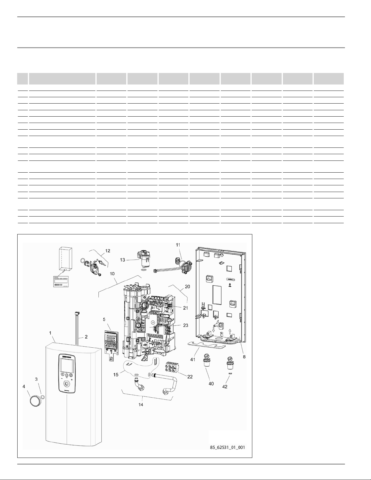
18. Spare parts
No. Spare part DHX 3.5-1
Trend
DHX 6-2
Trend
DHX 8-2
Trend
DHX 10-2
Trend
DHX 12-2
Trend
DHX 12-2
Plus
DHX 15-2
Trend
DHX 15-2
Plus
1 Housing (front) 348149 348149 348149 348149 348149 348148 348149 348148
2 PCB connection cable 158010 158010 158010 158010 158010 158010 158010 158010
3 O-Ring 9.5x2 EPDM 269351 269351 269351 269351 269351 269351 269351 269351
4 Control knob 323686 323686 323686 323686 323686 323686 323686 323686
5 LCD display 349445 349445 349445 349445 349445 349333 349445 349333
8 Housing (back) 348144 348144 348144 348144 348144 348144 348144 348144
10 Heating system 344153 344154 344152 344152 344150 344147 344150 344147
11 Flow sensor 339979 339979 339979 339979 339979 339979 339979 339979
12 Self-resetting high limit safety
cut-out, Klixon, with outlet sensor
340528 340528 340528 340528 340528 340528 340528 340528
13 Motorized valve - - - - - 220502 - 220502
14 Pipe elbow set 340542 340542 340542 340542 340542 340542 340542 340542
15 Pipe elbow connection set
(includes clips and gaskets)
320540 320540 320540 320540 320540 320540 320540 320540
20 PCB electronic board 348500 348501 348502 348503 348504 348498 348505 348499
21 Jumper plug (red) 283455 283455 283455 283455 283455 283455 283455 283455
22 Wiring block 326655 326655 326655 326655 326655 326655 326655 326655
23 Electronics cover 344146 344146 344146 344146 344146 344146 344146 344146
40 Water connection fittings (2) -
½˝NPT / G⅜˝
326589 326589 326589 326589 326589 326589 326589 326589
41 Locking sheet 326234 326234 326234 326234 326234 326234 326234 326234
42 Filter screen 275981 275981 275981 275981 275981 275981 275981 275981
ENGLISH
www.stiebel-eltron-usa.com DHX Trend & DHX Plus | 25
WARRANTY | ENVIRONMENT AND RECYCLING
GUARANTEE
ENVIRONMENT AND RECYCLING
This Warranty is valid for U.S.A. & Canada only. Warranties may
vary by country. Please consult your local Stiebel Eltron Repre-
sentative for the Warranty for your country.
!
The installation, electrical connection and first operati-
on of this appliance should be carried out by a qualified
installer.
!
The company does not accept liability for failure of any
goods supplied which have not been installed and ope-
rated in accordance with the manufacturer‘s
instructions.
Environment and recycling
Please help us to protect the environment by disposing of the
packaging in accordance with the national regulations for waste
processing.
Subject to the terms and conditions set forth in this limited
warranty, Stiebel Eltron, Inc. (the “Manufacturer”) hereby
warrants to the original purchaser (the “Owner”) that each
Tankless Electric Domestic Hot Water Heater (the “Heater”)
shall not (i) leak due to defects in the Manufacturer’s
materials or workmanship for a period of seven (7) years
from the date of purchase or (ii) fail due to defects in the
Manufacturer’s materials or workmanship for a period of
three (3) years from the date of purchase. As Owner’s sole
and exclusive remedy for breach of the above warranty,
Manufacturer shall, at the Manufacturer’s discretion,
send replacement parts for local repair; retrieve the unit
for factory repair, or replace the defective Heater with a
replacement unit with comparable operating features.
Manufacturer’s maximum liability under all circumstances
shall be limited to the Owner’s purchase price for the
Heater.
This limited warranty shall be the exclusive warranty
made by the Manufacturer and is made in lieu of all other
warranties, express or implied, whether written or oral,
including, but not limited to warranties of merchantability
and fi tness for a particular purpose. Manufacturer shall
not be liable for incidental, consequential or contingent
damages or expenses arising directly or indirectly from any
defect in the Heater or the use of the Heater. Manufacturer
shall not be liable for any water damage or other damage
to property of Owner arising, directly or indirectly,
from any defect in the Heater or the use of the Heater.
Manufacturer alone is authorized to make all warranties
on Manufacturer’s behalf and no statement, warranty or
guarantee made by any other party shall be binding on
Manufacturer.
Manufacturer shall not be liable for any damage
whatsoever relating to or caused by:
1. any misuse or neglect of the Heater, any accident to
the Heater, any alteration of the Heater, or any other
unintended use;
2. acts of God and circumstances over
which Manufacturer has no control;
3. installation of the Heater other than as directed by
Manufacturer and other than in accordance with
applicable building codes;
4. failure to maintain the Heater or to operate the Heater
in accordance with the Manufacturer’s specifi cations;
5. operation of the Heater under fl uctuating water
pressure or in the event the Heater is supplied with
non-potable water, for any duration;
6. improper installation and/or improper materials used
by any installer and not relating to defects in parts or
workmanship of Manufacturer;
7. moving the Heater from its original place of installation;
8. exposure to freezing conditions;
9. water quality issues such as corrosive water, hard water,
and water contaminated with pollutants or additives;
Should owner wish to return the Heater to manufacturer
for repair or replacement under this warranty, Owner
must fi rst secure written authorization from Manufacturer.
Owner shall demonstrate proof of purchase, including a
purchase date, and shall be responsible for all removal
and transportation costs. If Owner cannot demonstrate a
purchase date this warranty shall be limited to the period
beginning from the date of manufacture stamped on the
Heater. Manufacturer reserves the right to deny warranty
coverage upon Manufacturer’s examination of Heater.
This warranty is restricted to the Owner and cannot be
assigned.
Some States and Provinces do not allow the exclusion
or limitation of certain warranties. In such cases, the
limitations set forth herein may not apply to the Owner. In
such cases this warranty shall be limited to the shortest
period and lowest damage amounts allowed by law. This
warranty gives you specifi c legal rights and you may also
have other rights which vary from State to State or Province
to Province.
Owner shall be responsible for all labor and other charges
incurred in the removal or repair of the Heater in the fi eld.
Please also note that the Heater must be installed in such a
manner that if any leak does occur, the fl ow of water from
any leak will not damage the area in which it is installed.
19. Warranty

26 | DHX Trend y DHX Plus www.stiebel-eltron-usa.com
TABLA DE CONTENIDO
GUÍA RÁPIDA DE INICIO
INFORMACIÓN ESPECIAL
FUNCIONAMIENTO
1. Información general __________________________________________29
1.1 Instrucciones de seguridad ______________________________________29
1.2 Otros símbolos que aparecen en esta documentación _____29
1.3 Unidades de medida ______________________________________________29
2. Seguridad ______________________________________________________29
2.1 Uso correcto ________________________________________________________29
2.2 Instrucciones generales de seguridad _________________________29
2.3 Símbolos de prueba _______________________________________________30
2.4 Licencias/certificados _____________________________________________30
3. Registre su producto _________________________________________30
4. Descripción del calentador de agua_________________________31
5. Configuraciones y pantallas __________________________________31
5.1 Interfaz de usuario de DHX Trend ______________________________31
5.2 Interfaz de usuario de DHX Plus ________________________________32
5.3 Generalidades de la pantalla del DHX Plus___________________32
5.4 Utilización de la pantalla _________________________________________32
5.5 Pantalla del DHX Trend ___________________________________________33
5.6 Pantalla del DHX Plus _____________________________________________33
5.7 Configuraciones recomendadas ________________________________37
6. Limpieza, cuidado y mantenimiento ________________________37
7. Resolución de problemas ____________________________________38
INSTALACIÓN
8. Seguridad ______________________________________________________38
8.1 Instrucciones generales de seguridad _________________________38
8.2 Instrucciones, normas y regulaciones _________________________38
9. Descripción del calentador de agua_________________________38
9.1 Entrega común _____________________________________________________38
10. Preparativos ___________________________________________________39
10.1 Lugar de instalación _______________________________________________39
10.2 Espacios libres mínimos __________________________________________39
11. Instalación _____________________________________________________39
11.1 Instalación estándar en la pared _______________________________39
11.2 Conexiones de agua _______________________________________________40
11.3 Instalación del aireador en el grifo conectado ______________41
11.4 Conexión eléctrica _________________________________________________41
11.5 Conexión eléctrica con un cable de alimentación corto ___42
11.6 Bloque de cableado _______________________________________________42
12. Puesta en marcha _____________________________________________42
12.1 Protección interna anti-escaldadura a través de la
ranura de puente __________________________________________________42
12.2 Puesta en marcha inicial _________________________________________43
12.3 Operación con agua precalentada _____________________________44
12.4 Reinicio ______________________________________________________________44
13. Apagado del calentador de agua ____________________________44
14. Información para servicio técnico ___________________________44
15. Mantenimiento ________________________________________________44
15.1 Drenaje del calentador de agua ________________________________44
15.2 Limpieza de la malla del filtro __________________________________45
16. Resolución de problemas ____________________________________46
17. Especificación __________________________________________________48
17.1 Dimensiones y conexiones _______________________________________48
17.2 Diagramas de cableado __________________________________________48
17.3 Salida del ACS ______________________________________________________49
17.4 Áreas de aplicación/tabla de conversión _____________________49
17.5 Condiciones de falla _______________________________________________49
17.6 Tabla de datos ______________________________________________________50
18. Repuestos ______________________________________________________51
19. Garantía ________________________________________________________52
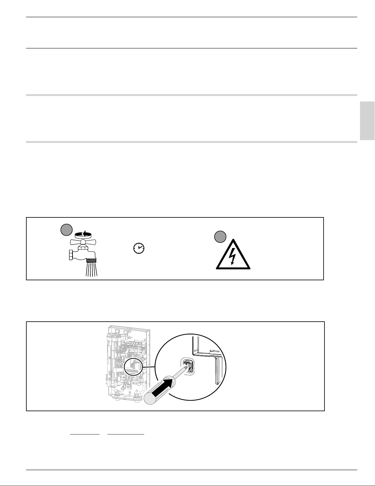
GUÍA RÁPIDA DE INICIO
ESPAÑOL
www.stiebel-eltron-usa.com DHX Trend y DHX Plus | 27
GUÍA RÁPIDA DE INICIO
Antes de encender el calentador de agua, DEBE eliminar todo el aire del siste-
ma y luego activar el interruptor de seguridad AE3. La unidad NO funcionará
hasta el interruptor de seguridad AE3 no se encuentre activado.
1 Monte la unidad en la pared (Consulte la sección 11.1, “Instalación estándar en la pared”, pág.
39).
2 Conecte las conexiones de agua (Consulte la sección 11.2, “Conexiones de agua”, pág. 40).
3 Conecte las conexiones eléctricas, pero mantenga el interruptor apagado. (Consulte la sección
11.4, “Conexión eléctrica”, pág. 41)
PLQ
1
2
Abra el
grifo
Encienda la
fuente de
alimenta-
ción.
D0000053277
4 Abra y cierre todas las válvulas de salida conectadas al menos 5 veces, durante al menos 3 mi-
nutos en total, hasta que se haya purgado todo el aire de la tubería y el calentador de agua.
5 Asegúrese de que no haya fugas de agua en ninguna conexión de plomería.
D0000094561-b
6 Active el interruptor de seguridad AE3 presionando firmemente el botón blanco de reinicio
hasta que haga clic y se bloquee en su lugar (el calentador de agua se entrega con el interrup-
tor de seguridad desactivado).
7 Encienda el calentador de agua accionando el interruptor del panel de interruptores.

INFORMACIÓN ESPECIAL
28 | DHX Trend y DHX Plus www.stiebel-eltron-usa.com
INFORMACIÓN
ESPECIAL
- Lea todo este manual. El incumplimiento de todas las
guías, instrucciones y normas puede causar lesiones
personales o daños a la propiedad. La instalación, el
ajuste, la alteración, el servicio y el uso incorrectos
de esta unidad pueden provocar lesiones graves.
- Esta unidad debe ser instalada por un electricista y
plomero autorizado. La instalación debe cumplir con
todos los códigos de plomería y electricidad nacio-
nales, estatales y locales. La instalación correcta es
responsabilidad del instalador. El incumplimiento de
las instrucciones de instalación y funcionamiento o el
uso incorrecto anulan la garantía.
- Guarde estas instrucciones para referencia futu-
ra. El instalador debe dejar estas instrucciones al
consumidor.
- Si tiene alguna consulta con respecto a la instala-
ción, el uso o el funcionamiento de este calentador
de agua, o si necesita manuales de instalación adi-
cionales, comuníquese con nuestra línea de servicio
técnico al 800.582.8423 (solo para EE.UU. y Canadá).
Si llama desde fuera de EE.UU. o Canadá, llame al
número 413.247.3380 de EE.UU. y lo derivaremos a un
asesor calificado de servicio de Stiebel Eltron dentro
de su área.
- El calentador de agua es adecuado para suministrar
una ducha en muchos climas (funcionamiento de la
ducha). Si el calentador de agua se utiliza también o
exclusivamente para el funcionamiento de la ducha,
el contratista cualificado debe ajustar el rango de
ajuste de la temperatura a 122 °F (50 °C) o menos
utilizando la protección interna antiquemaduras del
calentador de agua. Cuando se utilice agua preca-
lentada, debe asegurarse de que la temperatura de
entrada no supere los 131 °F (55 °C).
- El voltaje especificado debe coincidir con la fuente de
alimentación. Consulte la placa de identificación en el
lado derecho del calentador de agua.
- Asegúrese de que el calentador de agua pueda se-
pararse de la fuente de alimentación mediante un
disyuntor que desconecte todos los polos con una se-
paración de contacto de al menos 1/8 pulg. (3 mm).
- PRECAUCIÓN: NO INSTALE EL CALENTADOR DENTRO
DE UNA MAMPARA DE BAÑO O MAMPARA DE DUCHA
NI LO CONECTE A UN ABLANDADOR DE AGUA DE SAL
REGENERANTE O A UN SUMINISTRO DE AGUA SALA-
DA.
PARA USO EN UN CIRCUITO DE RAMA INDIVIDUAL
SOLAMENTE
PRECAUCIÓN: CONECTAR SOLO A UN CIRCUITO PRO-
TEGIDO POR UN INTERRUPTOR DIFERENCIAL CLASEA
USE SÓLO CONDUCTORES DE COBRE
USE EL CONDUCTOR DE UNIÓN ADECUADO SEGÚN EL
CÓDIGO ELÉCTRICO CANADIENSE, PARTE I
- El calentador de agua debe estar correctamente co-
nectado a tierra. Consulte la sección 17.2, “Diagramas
de cableado”, pág. 48.
- El calentador de agua debe estar conectado perma-
nentemente a un cableado fijo. Solo se debe usar en
un circuito derivado individual. Consulte la sección
17.2, “Diagramas de cableado”, pág. 48.
- Asegure el calentador de agua como se describe en
el capítulo 11, “Instalación”, pág. 39.
- Respete la presión mínima permitida de 26.1 psi (1.8
bar). Consulte la sección 17.6, “Tabla de datos”, pág.
50.
- Respete la presión mínima permitida de 145 psi (10
bar). Consulte la sección 17.6, “Tabla de datos”, pág.
50.
- Drene el calentador de agua como se describe en la
sección 15.1, “Drenaje del calentador de agua”, pg.
44.
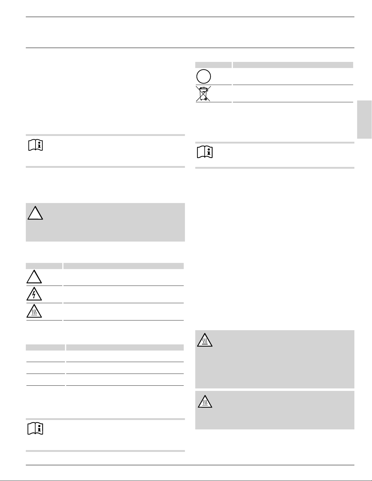
FUNCIONAMIENTO
Información general
ESPAÑOL
www.stiebel-eltron-usa.com DHX Trend y DHX Plus | 29
FUNCIONAMIENTO
1. Información general
Los capítulos “Información especial” y “Funcionamiento” están des-
tinados tanto a usuarios como a técnicos calificados.
El capítulo “Instalación” está destinado a técnicos calificados.
Nota
Lea estas instrucciones con detenimiento antes de usar el
calentador de agua y consérvelas para referencia futura.
Si es necesario, pase las instrucciones a un nuevo usuario.
1.1 Instrucciones de seguridad
1.1.1 Estructura de las instrucciones de seguridad
!
PALABRA CLAVE Tipo de riesgo
A continuación, se enumeran las posibles consecuencias
que pueden resultar del incumplimiento de las instruccio-
nes de seguridad.
f Se indica cómo prevenir el riesgo.
1.1.2 Símbolos y tipos de riesgo
Símbolo Tipo de riesgo
Lesiones
Electrocución
Quemaduras
(quemaduras, escaldaduras)
1.1.3 Palabras clave
PALABRA CLAVE Significado
PELIGRO El incumplimiento de esta información provocará lesiones
graves o la muerte.
ADVERTENCIA El incumplimiento de esta información puede provocar le-
siones graves o la muerte.
PRECAUCIÓN El incumplimiento de esta información puede provocar le-
siones no graves o leves.
1.2 Otros símbolos que aparecen en esta
documentación
Nota
La información general se identifica con el símbolo adya-
cente.
f Lea estos textos cuidadosamente.
Símbolo Significado
Pérdidas materiales
(Daño del calentador de agua, pérdidas indirectas y contami-
nación ambiental)
Eliminación del aparato
f Este símbolo indica que usted tiene que hacer algo. La acción
que debe realizar se describe paso a paso.
1.3 Unidades de medida
Nota
Todas las medidas se dan en pulgadas (milímetros), a
menos que se indique lo contrario.
2. Seguridad
2.1 Uso correcto
Este calentador de agua es adecuado para calentar agua caliente
doméstica o para recalentar agua precalentada. El calentador de
agua puede suministrar uno o más puntos de extracción.
El agua no se recalentará si se supera la temperatura máxima de
entrada para el recalentamiento.
El calentador de agua está destinado al uso doméstico. Puede ser
utilizado con seguridad por personas no capacitadas. El calentador
de agua también puede utilizarse en entornos no domésticos, por
ejemplo en pequeñas empresas, siempre que se utilice de la misma
manera.
Cualquier otro uso más allá del descrito se considerará inapropia-
do. La observación de estas instrucciones y de las instrucciones de
cualquier accesorio utilizado también forma parte del uso correcto
de este calentador de agua.
2.2 Instrucciones generales de seguridad
PELIGRO Quemaduras
Las temperaturas de agua superiores a 125 °F (52 °C) pue-
den causar quemaduras graves al instante o muerte por
quemadura. Si el puente del calentador de agua está de-
masiado alto, puede causar quemaduras. Si en su hogar
hay niños pequeños o personas mayores o discapacitadas,
puede ajustar el puente a 110 °F (43 °C) o menos para evitar
posibles lesiones por agua caliente.
PRECAUCIÓN Quemaduras
Si funciona con agua precalentada, por ejemplo, de un
sistema térmico solar, la temperatura del agua caliente
sanitaria (ACS) puede variar de la temperatura estable-
cida.
!
!
FUNCIONAMIENTO
Registre su producto
30 | DHX Trend y DHX Plus www.stiebel-eltron-usa.com
PRECAUCIÓN Quemaduras
Durante el funcionamiento, el grifo puede alcanzar tem-
peraturas de hasta 149 °F (65 °C).
Existe riesgo de quemaduras cuando la temperatura del
agua que sale supera los 110 °F (43 °C).
!
PELIGRO Lesiones
Por favor lea y siga estas instrucciones. El incumplimiento
de estas instrucciones puede provocar lesiones personales
graves o la muerte.
!
PRECAUCIÓN: NO INSTALE EL CALENTADOR DENTRO DE
UNA MAMPARA DE BAÑO O MAMPARA DE DUCHA NI
LO CONECTE A UN ABLANDADOR DE AGUA DE SAL
REGENERANTE O A UN SUMINISTRO DE AGUA SALADA.
PARA USO EN UN CIRCUITO DE RAMA INDIVIDUAL SOLA-
MENTE
PRECAUCIÓN: CONECTAR SOLO A UN CIRCUITO PRO-
TEGIDO POR UN INTERRUPTOR DIFERENCIAL CLASE A
USE SÓLO CONDUCTORES DE COBRE
USE EL CONDUCTOR DE UNIÓN ADECUADO SEGÚN EL CÓDI-
GO ELÉCTRICO CANADIENSE, PARTE I
PELIGRO ELECTROCUCIÓN
ANTES DE PROCEDER CON CUALQUIER INSTALACIÓN,
AJUSTE, ALTERACIÓN O SERVICIO TÉCNICO DE ESTE APA-
RATO, TODOS LOS DISYUNTORES E INTERRUPTORES DE
CONEXIÓN QUE LO ALIMENTAN DEBEN ESTAR APAGA-
DOS. DE LO CONTRARIO, PODRÍAN PRODUCIRSE LESIO-
NES PERSONALES GRAVES O LA MUERTE.
ADVERTENCIA ELECTROCUCIÓN
NUNCA QUITE NI VUELVA A COLOCAR LA CUBIERTA DEL
CALENTADOR DE AGUA SIN DESCONECTAR LA ELECTRICI-
DAD. DE LO CONTRARIO, PODRÍAN PRODUCIRSE LESIO-
NES PERSONALES GRAVES O LA MUERTE.
ADVERTENCIA Electrocución
TLa conexión a la fuente de alimentación sólo está per-
mitida como conexión permanente en conjunción con una
pinza Romex ¾ pulg. Asegúrese de que el calentador de
agua puede ser separado de la fuente de alimentación
por un aislante que desconecte todos los polos con al
menos 1/8 pulg. (3 mm) de separación de contactos.
!
DAÑOS AL CALENTADOR DE AGUA Y AL MEDIO AMBIEN-
TE:
El calentador de agua debe ser instalado por un electricis-
ta y un plomero con licencia. La instalación debe cumplir
con todos los códigos nacionales, estatales y locales de
plomería y electricidad.
El servicio del calentador de agua debe ser realizado por
técnicos de servicio cualificados.
!
DAÑOS AL CALENTADOR DE AGUA Y AL MEDIO AMBIEN-
TE:
Este aparato debe estar alimentado por un sistema co-
nectado a tierra. Se proporciona un terminal verde (o
un conector de cable marcado “G”, “GR”, “GROUND” O
“GROUNDING”) para el cableado del aparato. Para redu-
cir el riesgo de descarga eléctrica, conecte este terminal
o conector al terminal de conexión a tierra del servicio
eléctrico o al panel de suministro a través de un cable de
cobre continuo que cumpla con lo estipulado en el código
de instalación eléctrica.
!
ADVERTENCIA Lesiones
Cuando se permita a niños o personas con capacidades
físicas, sensoriales o mentales limitadas controlar este
calentador de agua, asegúrese de que esto sólo se haga
bajo supervisión o tras las instrucciones apropiadas de
una persona responsable de su seguridad. Los niños deben
ser supervisados para asegurar que nunca jueguen con el
calentador de agua.
En los casos en que se permita a los niños o a las personas con
capacidades físicas, sensoriales o mentales limitadas utilizar este
calentador de agua, recomendamos un límite de temperatura per-
manente. Las siguientes opciones de limitación están disponibles:
- Ajustable por el usuario: Límite de temperatura (a prueba de
niños)
- Contratista calificado ajustable: “Protección interna
anti-escaldadura”
!
Pérdidas materiales
El usuario debe proteger el calentador de agua de la es-
carcha.
2.3 Símbolos de prueba
Consulte la placa de identificación del calentador de agua.
2.4 Licencias/certificados
- UL (EE.UU.) Std. 499
- CSA (Canadá) Std. C22.2 No. 64
3. Registre su producto
Debe registrar este producto en un plazo de 90 días a
partir de la fecha de compra en nuestro sitio web para
activar la garantía estándar. Vaya a nuestro sitio web
en www.stiebel-eltron-usa.com y haga clic en “Regis-
tre su producto” (Register Your Product).
Antes de comenzar el proceso de registro, le sugerimos que re-
copile la siguiente información que necesitará:
Tipo, ejemplo: DHX 15-2 Plus (de la etiqueta que está en la uni-
dad)
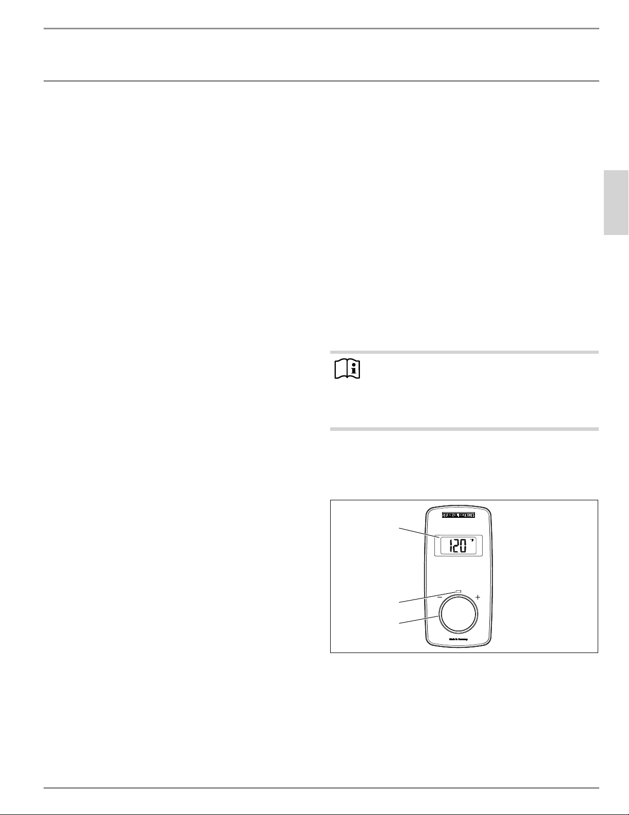
FUNCIONAMIENTO
Descripción del calentador de agua
ESPAÑOL
www.stiebel-eltron-usa.com DHX Trend y DHX Plus | 31
El número que aparece después de “No.”
Lugar de compra
Fecha de compra
Nombre y apellido
Dirección de correo electrónico
Dirección postal
Número de teléfono
Fecha de instalación
Si tiene alguna pregunta en relación con el proceso de registro
o con las opciones de garantía, por favor, póngase en contacto
directamente con Stiebel Eltron USA en el número de teléfono
(800)-582-8423.
4. Descripción del calentador de agua
El calentador de agua se enciende automáticamente tan pronto
como se abre una válvula de agua caliente en un grifo u otro punto
de extracción. El DHX calienta el agua a medida que fluye por la
unidad. Cuando se cierra el grifo, el calentador de agua se apaga
automáticamente.
A partir del caudal de activación, la unidad de control electrónico
regula la salida de calefacción correcta utilizando sólo la cantidad
mínima de potencia necesaria, en función de la temperatura selec-
cionada y la temperatura actual del agua fría entrante.
DHX Trend y DHX Plus son calentadores de agua sin tanque con-
trolados electrónicamente, y mantienen una temperatura de salida
constante. Esto es independiente de la temperatura del agua de
entrada, hasta la máxima salida del calentador de agua.
Los modelos DHX Plus cuentan con Control de Flujo Avanzado
™
, una
tecnología patentada por Stiebel Eltron en Alemania (patente no.
DE 3805441 C2). Cuando se alcanza la salida máxima de un modelo
DHX Plus, en lugar de desviarse de la temperatura de consigna y
suministrar agua más fría, los modelos DHX Plus utilizan una válvula
motorizada controlada electrónicamente para reducir ligeramente
el flujo de agua sólo lo necesario para mantener la temperatura se-
leccionada por el usuario. Cuando la demanda puede ser satisfecha
completamente de nuevo, la válvula motorizada regresa a la posición
totalmente abierta, permitiendo el flujo completo. Esto asegura un
confort ininterrumpido, y agua caliente a la temperatura deseada
en todo momento.
Si el calentador de agua funciona con agua precalentada, y la tempe-
ratura de entrada supera la temperatura establecida seleccionada,
la temperatura de entrada se mostrará en la segunda fila de la
pantalla (sólo en los modelos DHX Plus) y parpadeará. El agua no
se calienta más.
Los modelos DHX están equipados con funciones para limitar la
temperatura de forma permanente (protección infantil).
Los modelos DHX Plus cuentan con una pantalla retroiluminada que
se enciende automáticamente en cuanto el agua fluye por la unidad
o si se realiza un cambio en la interfaz de usuario. La retroilumina-
ción se apaga automáticamente si no se realizan cambios durante
30 segundos, o 5 segundos después de que el agua caliente deja
de ser extraída.
Los modelos DHX Plus permiten al usuario guardar diferentes tem-
peraturas preestablecidas y aplicarlas rápidamente.
Los modelos DHX Plus también ofrecen una pantalla de 2 líneas más
profunda con funciones mejoradas. El modelo DHX Trend tiene una
pantalla de una sola línea y un conjunto de funciones más básicas
para el usuario.
Temperatura del agua caliente sanitaria (ACS)
La temperatura de salida del agua caliente se puede ajustar de
forma variable entre 68–140 °F (20–60 °C). Se muestra la temperatura
seleccionada.
Sistema de calefacción
El sistema de calentamiento en espiral está compuesto por una cá-
mara de calentamiento de poliamida reforzada con vidrio y probada
a presión, con una bobina de calentamiento directo de alambre de
níquel. Es adecuado para zonas de aguas duras y blandas y es en
gran medida insensible a la acumulación de incrustaciones. El sis-
tema de calentamiento en espiral garantiza una producción rápida
y eficiente de agua caliente.
Nota
El calentador de agua está equipado con un detector de aire
que evita el daño al sistema de calentamiento. Si, durante
el funcionamiento, ingresa aire al calentador de agua, el
calentador de agua apagará la salida de calor durante un
minuto para proteger el sistema de calentamiento.
5. Configuraciones y pantallas
5.1 Interfaz de usuario de DHX Trend
2
3
1
1 Pantalla
2 LED de funcionamiento (parpadea cuando se alcanza el límite
de salida)
3 Perilla de control
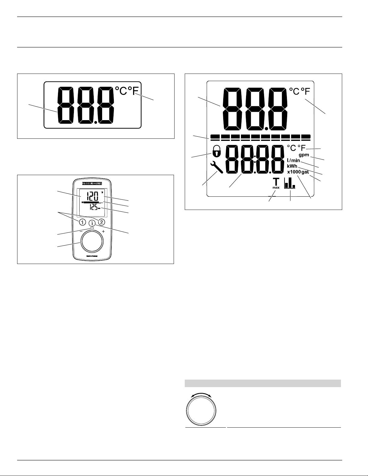
FUNCIONAMIENTO
ĒĉÐÖşļ|êĒĉ¼ńźĤ|ĉŒ|ùù|ń
32 | DHX Trend y DHX Plus www.stiebel-eltron-usa.com
5.1.1 Generalidades de la pantalla del DHX Trend
1
2
1 Pantalla de dígitos
2 Indicador de la unidad de temperatura
5.2 Interfaz de usuario de DHX Plus
D0000073619
3
2
4
8
5
6
7
1
1 Pantalla con luz de fondo
2 Teclas de memoria de temperatura
3 LED de funcionamiento (parpadea cuando se alcanza el límite
de salida)
4 Perilla de control
5 Pantalla principal | pantalla de información | pantalla de
parámetros
6 Pantalla de segmentos [10–100%]
7 Segunda fila de la pantalla (sólo DHX Plus)
8 Botón “i” para recuperar la información y seleccionar los
menús
5.3 Generalidades de la pantalla del DHX Plus
1
2
3
4
6
7
8
9
10
11
12
13
14
5
1 Pantalla de dígitos primarios
2 Estado de la capacidad de energía
3 Indicador de bloqueo de la pantalla
4 Símbolo de código de error
5 Pantalla de dígitos secundarios
6 Indicador T
max
7 Indicador de estadísticas de ahorro
8 x1000 valor de la pantalla secundaria
9 Galones de la unidad de pantalla secundaria
10 kWh unidad de pantalla secundaria
11 Litros y litros por minuto de la pantalla secundaria
12 Unidad de pantalla secundaria de galones por minuto
13 Unidad de temperatura para la pantalla secundaria
14 Unidad de temperatura para la pantalla principal
5.4 Utilización de la pantalla
El DHX Trend y el DHX Plus presentan una pantalla interactiva que
permite la personalización para aumentar el nivel de comodidad
del usuario.
La estructura del menú está diseñada de forma intuitiva y lineal para
que sea lo más navegable posible.
5.4.1 Entrada del usuario del DHX Trend
Entrada del usuario
Perilla de control (gire la perilla para cambiar
la configuración)
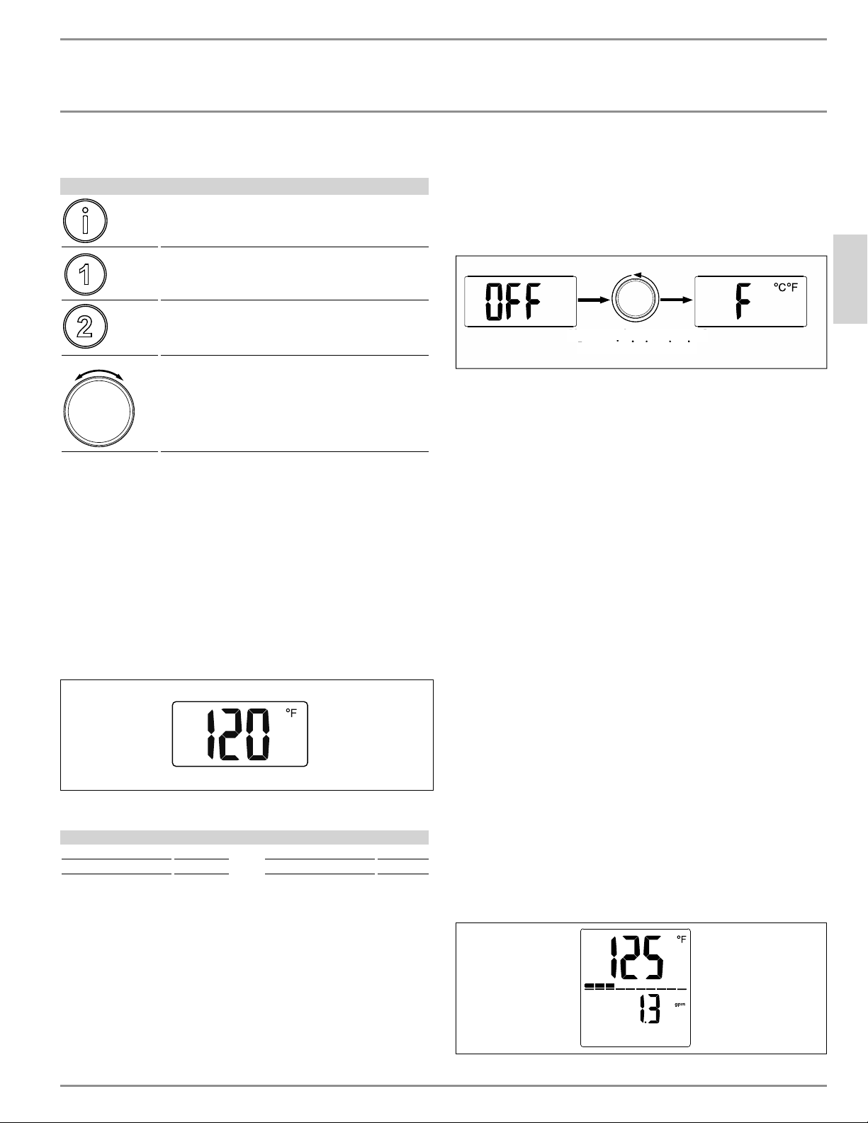
FUNCIONAMIENTO
ĒĉÐÖşļ|êĒĉ¼ńźĤ|ĉŒ|ùù|ń
ESPAÑOL
www.stiebel-eltron-usa.com DHX Trend y DHX Plus | 33
5.4.2 Entrada del usuario del DHX Plus
Entrada del usuario
Botón de información (presionar o mantener
presionado este botón realiza diferentes fun-
ciones)
Botón de preselección 1 (presionar o mantener
presionado este botón realiza diferentes fun-
ciones)
Botón de preselección 2 (presionar o mantener
presionado este botón realiza diferentes fun-
ciones)
Perilla de control (gire la perilla para cambiar
la configuración)
5.5 Pantalla del DHX Trend
La pantalla del DHX Trend tiene una lectura de temperatura capaz
de mostrar la temperatura seleccionada actualmente en Fahrenheit
o Celsius.
Para el nombre de cada elemento de la pantalla del DHX Trend,
consulte la sección 5.1.1, “Generalidades de la pantalla del DHX
Trend”, pág. 32.
5.5.1 Pantalla base
La pantalla base muestra el punto de ajuste de la temperatura actual
en su unidad de temperatura preferida.
Cambiar la temperatura de consigna
Ajustes de temperatura
Rango Incremento Rango Incremento
68–140 °F 1 °F 20–60 °C. 1 °C
La temperatura de consigna puede ajustarse entre 68 ° F (20 ° C) y
140 ° F (60 ° C).
Se puede subir la temperatura girando la perilla de control hacia
la derecha y puede bajarse girando la perilla hacia la izquierda. El
calentador de agua puede desactivarse aún cuando está encendido
al girar la perilla de control hacia la izquierda, pasando el ajuste
de 68 ° F (20 ° C).
5.5.2 Ajuste de parámetros de unidades de temperatura
El DHX Trend indica la temperatura en Fahrenheit o Celsius.
f Para cambiar entre Fahrenheit (predeterminado) y Celsius, pri-
mero gire la perilla de control hacia la izquierda hasta que en
la pantalla aparezca “Off”.
f Una vez que aparezca “Off” en la pantalla, gire el mando de
control 5 rotaciones completas de 360° hacia la izquierda. Esto
abrirá el menú de parámetros de temperatura:
Gira completamente 360°
5 veces a la izquierda
Gira completamente 360°
5
veces a
l
a
i
zqu
i
er
da
p
p
Se mostrará la unidad actual y la pantalla parpadeará para indicar
que se puede cambiar el valor. Gire el mando de control para cam-
biar el valor entre Fahrenheit y Celsius.
5.5.3 Retorno a la pantalla base
La pantalla volverá a la pantalla base después de un período de 30
segundos sin que el usuario la haya introducido.
5.6 Pantalla del DHX Plus
El DHX Plus cuenta con un área de visualización primaria y secun-
daria, lo que permite que se indiquen varios parámetros o datos
de información. El DHX Plus señala el nivel de flujo existente de
agua que pasa por el calentador de agua, como también calcula
los ahorros de costo acumulados al tener un calentador de paso, en
comparación con un calentador de agua con tanque.
Para consultar el nombre de cada componente de la pantalla del
DHX Plus, consulte la sección 5.3, “Generalidades de la pantalla del
DHX Plus”, pág. 32.
5.6.1 Pantalla base
La pantalla base señala el valor nominal de temperatura actual en su
unidad de temperatura preferida, en la parte superior de la pantalla.
La barra que se encuentra debajo de la temperatura indica la frac-
ción en curso de la capacidad total a la que funciona el calentador
de agua. A medida que la demanda de agua fluctúa, el estado de
capacidad de potencia se modifica e indica de 0 a 10 segmentos.
La siguiente pantalla señala que el calentador de agua funciona al
40% de su capacidad.
La parte inferior de la pantalla indica el nivel de flujo existente en
el calentador de agua, ya sea en galones por minuto (gpm) o en
litros por minuto (l/min).
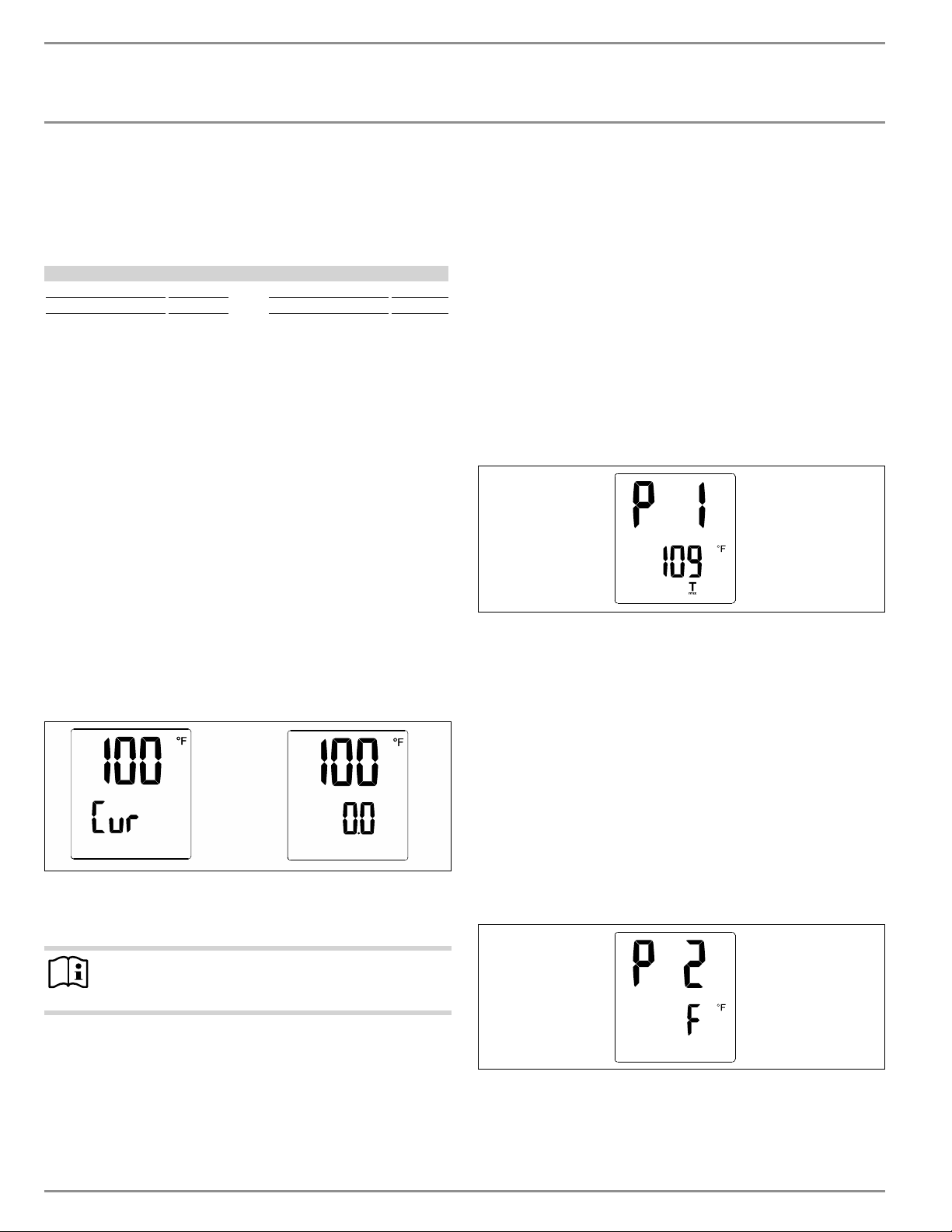
FUNCIONAMIENTO
ĒĉÐÖşļ|êĒĉ¼ńźĤ|ĉŒ|ùù|ń
34 | DHX Trend y DHX Plus www.stiebel-eltron-usa.com
Todos los demás menús volverán a la pantalla base ya sea después
de un período de 15 segundos sin la entrada del usuario, o des-
pués de mantener presionado el botón de información durante 5
segundos.
Cambiar la temperatura de consigna
Ajustes de temperatura
Rango Incremento Rango Incremento
68–140 °F 1 °F 20–60 °C 0.5 °C
La temperatura de consigna puede ajustarse entre 68 °F (20 °C) y
140 °F (60 °C).
Se puede subir la temperatura girando la perilla de control hacia
la derecha y puede bajarse girando la perilla hacia la izquierda. El
calentador de agua puede desactivarse aún cuando está encendido
al girar la perilla de control hacia la izquierda, pasando el ajuste
de 68 °F (20 °C).
5.6.2 Menú de información
El sistema del menú de información indica datos adicionales para el
usuario. Para acceder al menú de información, se debe presionar el
botón de información en la pantalla base.
Pantalla de ahorro de costos acumulados
Al presionar el botón de información en la pantalla principal, se
avanza a la pantalla de ahorro de costos acumulados.
La pantalla de ahorro de costes acumulados mostrará la temperatura
de consigna actual en la mitad superior de la pantalla, y la mitad
inferior de la pantalla alternará entre “Cur” y el ahorro acumulado
del calentador de agua.
La función de ahorros de costo se actualiza diariamente y señala los
ahorros aproximados que se le brinda al usuario, en comparación
con la instalación de un calentador de agua con tanque.
Nota
Los valores de ahorro de energía se calculan a partir del
último reinicio.
Esta aproximación de ahorros de costo se basa en el gasto de elec-
tricidad que tiene el usuario. Para lograr una aproximación lo más
precisa posible, el costo de electricidad por kWh debería estable-
cerse en el menú de configuración de los parámetros de costo de la
electricidad. Para consultar información sobre este paso, consulte
la sección, , “Ajuste de parámetros de costos de electricidad”, pág.
35.
Al presionar el botón de información se vuelve a la pantalla base.
También se regresará a la pantalla base si no se detecta ningún dato
de entrada por parte del usuario durante 10 segundos.
5.6.3 Menú de parámetros
El menú de parámetros permite la modificación de varias configu-
raciones. Se puede acceder al menú de parámetros sosteniendo el
botón de información por 5 segundos.
Ajuste de parámetros T
max
El menú del primer parámetro configura el valor de T
max
. El valor
de T
max
actúa como un limitador de altas temperaturas. Si el valor
T
max
está configurado, el valor predeterminado del calentador de
agua no puede configurarse por arriba del valor T
max
. Esta función
es útil en situaciones donde hay riesgo de quemaduras a causa de
agua muy caliente.
En el menú de ajuste de T
max
, la pantalla parpadea, lo que indica
que se puede cambiar el valor girando la perilla de control. El valor
T
max
puede aumentarse girando la perilla de control hacia la dere-
cha y disminuirse girándola hacia la izquierda. El valor T
max
puede
desactivarse al girar la perilla de control hacia la izquierda, pasando
la opción de 68 °F (20 °C). En la pantalla se indicará “Off” si el valor
T
max
está inactivo.
Si el símbolo T
max
está visible en la pantalla principal, entonces la
función T
max
se encuentra activa y, de esa manera, limita la tempe-
ratura máxima aceptable.
Al presionar una vez el botón de información en esta pantalla, se
avanza al ajuste de parámetros de unidades de temperatura.
Ajuste de parámetros de unidades de temperatura
El DHX Plus indica la temperatura en Fahrenheit o Celsius.
Se visualiza la unidad actual y el valor para la pantalla secundaria
parpadea con el fin de indicar que se puede modificar tal valor. Para
cambiar el valor de Fahrenheit a Celsius y viceversa, debe girarse
la perilla de control.
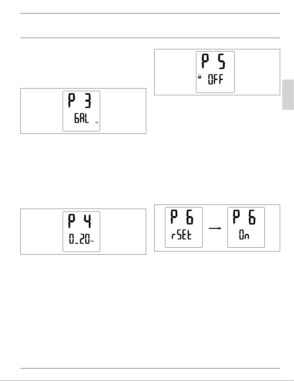
FUNCIONAMIENTO
ĒĉÐÖşļ|êĒĉ¼ńźĤ|ĉŒ|ùù|ń
ESPAÑOL
www.stiebel-eltron-usa.com DHX Trend y DHX Plus | 35
Al presionar una vez el botón de información en esta pantalla, se
avanza al ajuste de parámetros de unidades de volumen.
Ajuste de parámetros de unidades de volumen
El DHX Plus indica los volúmenes o el flujo de volumen en galones
por minuto (gpm) o litros por minuto (l/min).
Se indica la unidad actual de volumen y el valor parpadea con el fin
de indicar que se puede modificar. Para cambiar el valor de galones
por minuto a litros por minuto y viceversa, gire la perilla de control.
Al presionar una vez el botón de información en este menú, se
avanza al ajuste de parámetros de costos de electricidad.
Ajuste de parámetros de costos de electricidad
El DHX Plus tiene una función integrada que calcula el ahorro de
energía del calentador de agua, en comparación con el uso pro-
medio de energía de un calentador de agua con tanque. Para que
esta función sea precisa, el costo por kWh de electricidad debe
programarse en el software del aparato.
La pantalla secundaria parpadea para indicar que el valor puede
modificarse girando la perilla de control. Revise su factura de elec-
tricidad para calcular el costo de electricidad.
Al presionar una vez el botón de información en este menú, se
avanza al ajuste de parámetros de bloqueo de la pantalla.
Ajuste de parámetros de bloqueo de la pantalla
La pantalla puede bloquearse para prevenir una fácil alteración de
la temperatura. El menú comienza a parpadear, lo que indica que
el valor puede modificarse girando la perilla de control. Cuando
aparece “Off”, el bloqueo no está activo. La función de bloqueo está
activa cuando en la pantalla se lee “On”.
Si el parámetro de bloqueo de la pantalla está configurado en “On”
y el usuario sostiene el botón de información por 5 segundos o deja
que la pantalla quede en pausa por 15 segundos, el bloqueo de la
pantalla pasará a estar activo.
Cuando el bloqueo de la pantalla está activo, aparece un ícono de
candado en la pantalla principal y no se puede modificar ningún
parámetro. Para desactivar el bloqueo, sostenga el botón de infor-
mación por 12 segundos. De esa manera, desaparecerá el ícono
de candado de la pantalla y se podrán volver a modificar todos los
parámetros.
Al sostener una vez el botón de información en el menú de ajuste
de parámetros de bloqueo de la pantalla, se avanza al menú de
parámetros de reinicio a los ajustes de fábrica.
Parámetros de reinicio a los ajustes de fábrica
La temperatura nominal, los valores preestablecidos, la tempera-
tura y las unidades de volumen pueden reiniciarse a los ajustes de
fábrica.
La pantalla en su totalidad comenzará a parpadear con el fin de
indicar que el valor puede ser modificado girando la perilla de con-
trol. Cuando el valor está configurado en “On”, debe confirmarse
el reinicio sosteniendo tanto el Botón 1 como el Botón 2, al mismo
tiempo, por 5 segundos.
Al presionar una vez el botón de información, se avanza al menú de
parámetros de reinicio de ahorros de costos acumulados.
Parámetros de reinicio de ahorros de costos acumulados
Al igual que los parámetros de reinicio a los ajustes de fábrica, el
valor calculado de los ahorros de costos acumulados puede reini-
ciarse en cero.
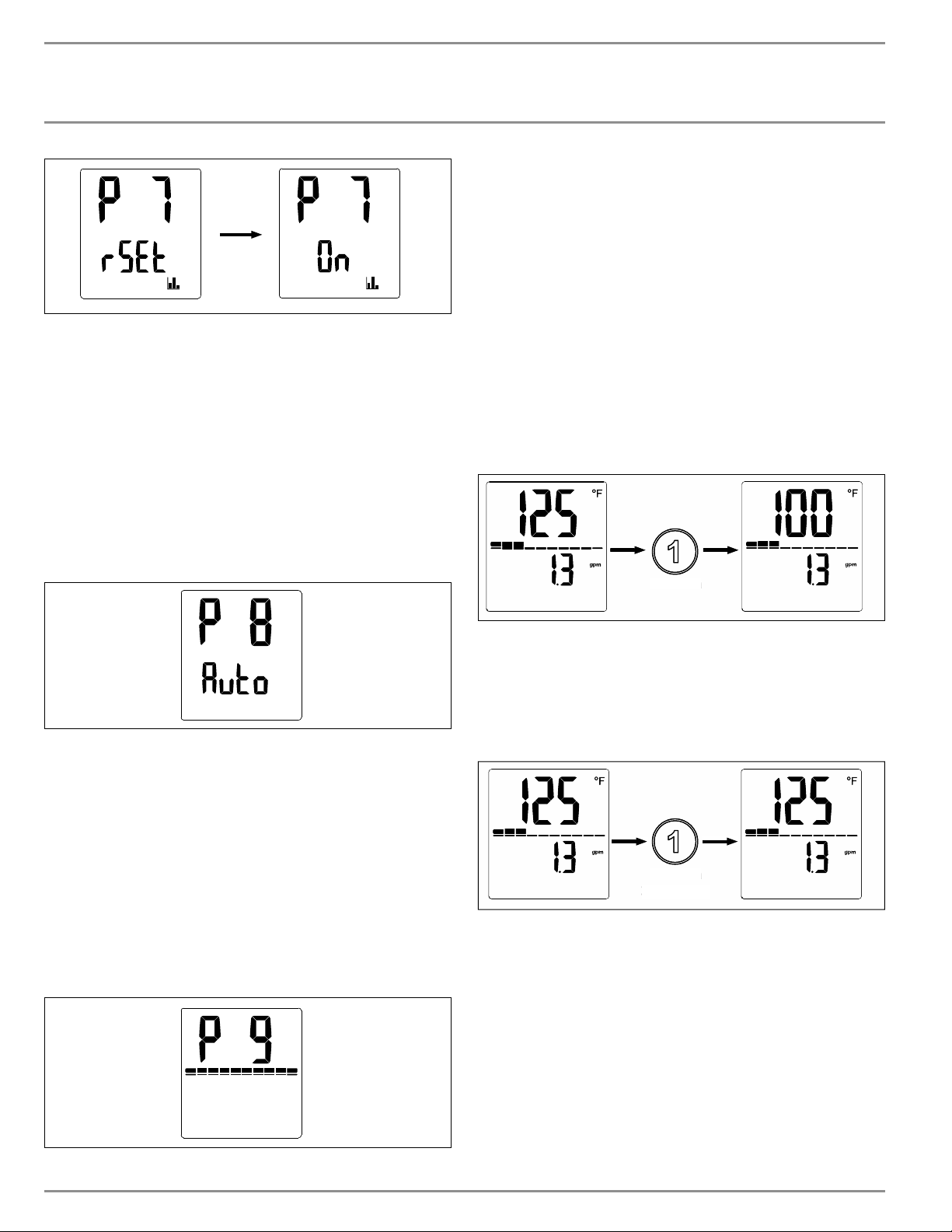
FUNCIONAMIENTO
ĒĉÐÖşļ|êĒĉ¼ńźĤ|ĉŒ|ùù|ń
36 | DHX Trend y DHX Plus www.stiebel-eltron-usa.com
La pantalla en su totalidad comenzará a parpadear, con el fin de
indicar que el valor puede modificarse girando la perilla de control.
Cuando el valor se encuentra en “On”, debe confirmarse el reinicio
sosteniendo tanto el Botón 1 como el Botón 2, al mismo tiempo,
por 5 segundos.
Al presionar una vez el botón de información, se avanza al menú
de los parámetros de pausa de la retroiluminación de la pantalla.
Parámetros de pausa de la retroiluminación de la pantalla
La retroiluminación de la pantalla puede ajustarse para que siem-
pre esté en “On” o puede ajustarse en modo automático, el cual
se desactiva cuando no se detectan datos de entrada del usuario
durante 30 segundos.
La pantalla en su totalidad y la retroiluminación comenzarán a par-
padear, con el fin de indicar que el valor puede modificarse girando
la perilla de control. Cuando el valor está ajustado en “Auto”, se des-
activará automáticamente después de 15 segundos de inactividad.
Al presionar una vez el botón de información en este menú, se
avanza al menú de parámetros de brillo de la retroiluminación de
la pantalla.
Parámetros de brillo de la retroiluminación de la pantalla
El brillo de la retroiluminación de la pantalla puede ajustarse a
dos parámetros diferentes. Un ajuste alto y bajo permite la perso-
nalización del usuario, según las condiciones de luz en el lugar de
instalación.
La barra de estado de la capacidad de potencia indica el ajuste de
brillo. Una barra a plena capacidad indica que el brillo está en la
configuración alta. Una barra a capacidad media indica que el brillo
está en el ajuste bajo.
Al presionar una vez el botón de información mientras se encuentra
en este menú, se volverá a la página de ajuste de parámetros T
max
,
marcada como “P1”.
5.6.4 Opciones de temperatura preestablecida
El DHX Plus cuenta con dos ajustes preestablecidos de temperatura
para permitir el acceso rápido a los puntos de ajuste. Tanto el Botón
1 como el Botón 2 almacenan un valor nominal independiente.
Modificación de valores nominales a valores preestablecidos
En la pantalla base, el usuario puede pulsar el Botón 1 o el Botón 2
para cambiar el valor nominal a los valores preestablecidos.
Presiona
P
res
i
on
a
Cuando se pulsa el botón, el valor nominal se modificará al valor
que estaba almacenado hasta ese punto.
Modificación de los valores preestablecidos
Los valores preestablecidos pueden modificarse y ser distintos a los
valores nominales de fábrica.
Presiona
3 segundos
Pr
es
i
o
n
a
3 segundo
s
Para cambiar el valor de preselección 1 o 2, en primer lugar gire
la perilla de control a la temperatura que desee ajustar. Luego,
mantenga pulsado el botón de preselección durante 3 segundos. La
pantalla comenzará a parpadear para indicar que el valor preesta-
blecido se ha cambiado correctamente.
5.6.5 Menú de error DHX Plus
Entras se muestra el ícono de la llave inglesa, pulse el botón de
información para avanzar a la página de visualización de errores.
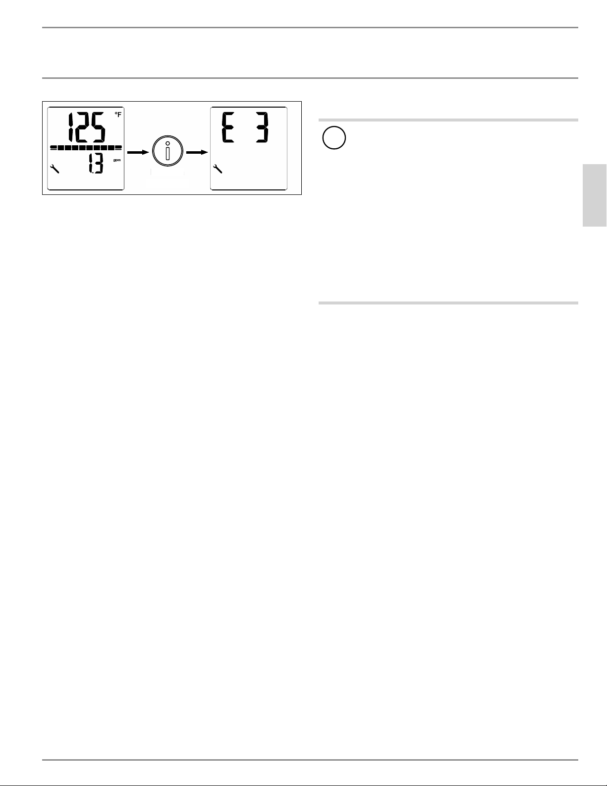
FUNCIONAMIENTO
Limpieza, cuidado y mantenimiento
ESPAÑOL
www.stiebel-eltron-usa.com DHX Trend y DHX Plus | 37
Presiona
5 segundos
Presiona
5
se
g
undo
s
Entras se muestra el ícono de la llave inglesa, pulse el botón de
información para avanzar a la página de visualización de errores.
Consulte la sección 16, “Resolución de problemas”, pág. 46, para
obtener información sobre cómo interpretar el código de error re-
portado.
5.6.6 Retorno a la pantalla base
Cuando se explora la pantalla y, en cualquier menú excepto en la
pantalla base, al sostener el botón de información por 5 segundos
se regresará a la pantalla base. Asimismo, se vuelve a la pantalla
base luego de un período de 15 segundos sin que el usuario ingrese
ningún dato.
5.7 Configuraciones recomendadas
Su calentador de agua eléctrico sin tanque ofrece la máxima como-
didad y precisión al proporcionar ACS. Si necesita operar el calen-
tador de agua con una válvula termostática, le recomendamos que:
f Ajuste la temperatura del calentador de agua a más de 122 °F
(50 °C). Luego ajuste la temperatura establecida requerida en
la válvula termostática.
Ahorro de energía
La siguiente configuración recomendada dará como resultado el
menor consumo de energía:
- 100 °F (38 °C) para lavamanos, duchas, baños
- 131 °F (55 °C) para fregaderos de cocina
Protección interna contra quemaduras (técnicos calificados)
Si es necesario, el técnico cualificado puede establecer un límite de
temperatura permanente, por ejemplo en guarderías, hospitales,
etc. Consulte la sección 12.1, “Protección interna anti-escaldadura
a través de la ranura de puente”, pág. 42.
Ajuste recomendado para el funcionamiento con una válvula
termostática y agua precalentada por energía solar
f Ajuste la temperatura del calentador de agua a la temperatura
máxima.
Después de una interrupción en el suministro de agua
!
Pérdidas materiales
Para asegurarse de que el sistema de calentamiento en
espiral no se dañe después de una interrupción en el su-
ministro de agua, debe seguir estos pasos para reiniciar el
calentador de agua.
f Apague la alimentación eléctrica de la unidad en el
panel de interruptores, asegurándose de que los inte-
rruptores de circuito conectados estén en la posición
“OFF”, para evitar cualquier peligro de descarga eléc-
trica.
f Abra y cierre el grifo al menos cinco veces durante un
total de tres minutos, hasta que no quede aire dentro
del calentador de agua ni de la línea de entrada de
agua fría.
f Vuelva a colocar los interruptores en la posición “ON”
para reconectar la alimentación eléctrica.
6. Limpieza, cuidado y mantenimiento
f Nunca use agentes de limpieza abrasivos o corrosivos. Use un
paño húmedo para limpiar el calentador de agua.
f Verifique los grifos regularmente. Se pueden eliminar los
depósitos de cal de las salidas de los grifos con agentes desin-
crustantes disponibles en el mercado.
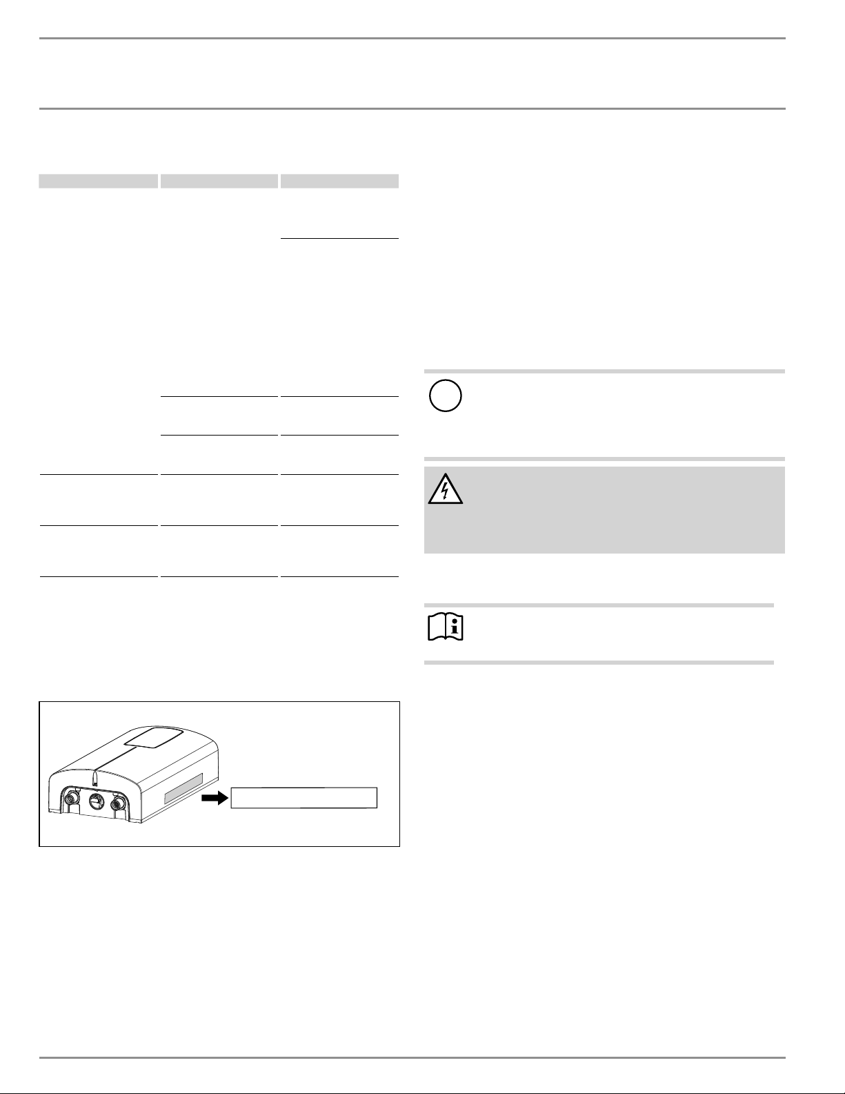
INSTALACIÓN
Resolución de problemas
38 | DHX Trend y DHX Plus www.stiebel-eltron-usa.com
7. Resolución de problemas
Problema Causa Solución
El calentador de agua no
arranca a pesar de que la
válvula de agua corrien-
te está completamente
abierta
No hay electricidad
Verifique si saltó el in-
terruptor del panel de
interruptores. Reinicie si
es necesario
No se activó el interruptor
blanco de seguridad AE3
durante la configuración
inicial. Actívelo si es nece-
sario (Consulte la sección
12.2.1, “Activación inicial
del interruptor de segu-
ridad AE3”, pág. 43). Si
el interruptor AE3 saltó
después de la instalación
inicial, comuníquese con
un técnico calificado para
solucionar la causa
El aireador del grifo o la
regadera tiene incrusta-
ciones o suciedad
Limpie y/o desincruste el
aireador o la regadera
Se ha interrumpido el su-
ministro de agua
Ventile el calentador de
agua y la línea de entrada
de agua fría
Cuando se extrae agua
caliente, por un período
corto, sale agua fría
El detector de aire detecta
aire en el agua. Se apaga
la salida de calor breve-
mente
El calentador de agua se
reinicia automáticamente
después de 1 minuto
No se puede establecer la
temperatura requerida
La protección interna
contra quemaduras está
activa
La protección interna
contra quemaduras solo
puede ser ajustada por
técnicos calificados
Si no puede resolver el problema, contacte con su contratista cua-
lificado. Para facilitar y acelerar su consulta, por favor proporcione
el número de serie de la placa de identificación (000000-0000-
000000). Para asistencia técnica en vivo, por favor contáctenos al
800.582.8423. Alternativamente, puede enviarnos un correo elec-
trónico a info@stiebel-eltron-usa.com
Nr.: 000000-0000-00000
D0000094552-b
INSTALACIÓN
8. Seguridad
Los trabajos de instalación, verificación y reparación del calentador
de agua solo deben ser realizados por un técnico calificado.
8.1 Instrucciones generales de seguridad
Garantizamos el funcionamiento sin problemas y la confiabilidad
operativa solo si se utilizan accesorios y repuestos originales desti-
nados al calentador de agua.
!
Pérdidas materiales
Respete la temperatura máxima de entrada. Las temperatu-
ras superiores pueden dañar el calentador de agua. Puede
limitar la temperatura máxima de entrada instalando una
válvula termostática central.
ADVERTENCIA Electrocución
Este calentador de agua contiene condensadores que se
descargan cuando se desconecta de la fuente de alimen-
tación. El voltaje de descarga del condensador puede ex-
ceder brevemente los 60 V CC.
8.2 Instrucciones, normas y regulaciones
Nota
Respete todas las regulaciones e instrucciones nacionales
y regionales pertinentes.
La resistividad eléctrica del agua no debe ser inferior a la indicada
en la placa de identificación. En una red de agua vinculada, tenga
en cuenta la resistividad eléctrica más baja del agua. Su empresa de
suministro de agua puede informarle sobre la resistividad eléctrica
o la conductividad del agua en su área.
9. Descripción del calentador de agua
9.1 Entrega común
Junto con el calentador de agua, se entregan:
- Malla de filtro, instalada de fábrica en la entrada de agua fría
- Puente de protección contra las quemaduras, conectado
- Puente de repuesto, conectado
- 2 x tornillos de montaje
- 2 x anclajes de pared
- Reductor de flujo/aerador de 0.5 gpm (1.9 l/min), DHX 3.5-1
Trend solamente. Consulte la sección 11.3, “Instalación
del aireador en el grifo conectado”, pág. 41, para más
información.
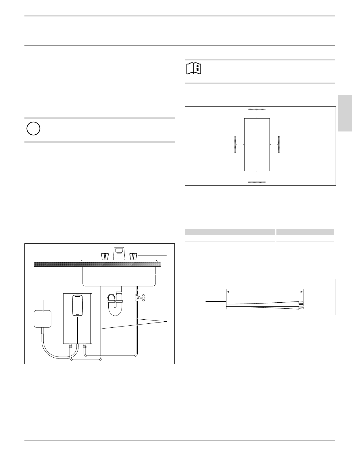
INSTALACIÓN
Preparativos
ESPAÑOL
www.stiebel-eltron-usa.com DHX Trend y DHX Plus | 39
- Reductor de flujo/aerador de 1.0 gpm (3.8 l/min), DHX 6-2
Trend solamente. Consulte la sección 11.3, “Instalación
del aireador en el grifo conectado”, pág. 41, para más
información.
10. Preparativos
10.1 Lugar de instalación
!
Pérdidas materiales
Instale el calentador de agua en una habitación en la que
no haya riesgo de escarcha.
f Instalar el DHX en un área libre de escarcha. Si puede haber
heladas, retire la unidad antes de que se fijen las temperaturas
de congelación.
f Siempre instale el calentador de agua de manera vertical, con
los accesorios de plomería apuntando hacia abajo. Instale el
calentador de agua cerca del punto de salida para minimizar
los tramos de tubería y las pérdidas térmicas.
f Grifos: No utilice grifos con válvula de venteo o grifos sin
presurizar.
El calentador de agua es adecuado para la instalación bajo el fre-
gadero y sobre el fregadero.
Típica instalación bajo el fregadero
D0000089950-a
6
5
1
3
2
7
4
1 Caja de conexiones eléctricas
2 ½ pulg. línea de suministro de agua para la instalación del
grifo
3 Válvula de cierre
4 Suministro de agua fría
5 Fregadero
6 Válvula fría (derecha)
7 Válvula caliente (izquierda)
Nota
f Instale el calentador de agua al ras de la pared. La
pared debe tener suficiente capacidad de carga.
10.2 Espacios libres mínimos
Ý
Ý
Ý
Ý
D0000079442
f Mantenga los espacios libres mínimos para garantizar un fun-
cionamiento sin problemas del calentador de agua y facilitar el
trabajo de mantenimiento.
11. Instalación
Ajustes de fábrica Todos los modelos DHX
Ajuste de temperatura interna en °F (°C) 140 °F (60 °C)
11.1 Instalación estándar en la pared
11.1.1 Preparación del cable de alimentación
4Ǭ–5ǩÝ (125–130 mm)
D0000094559-b
f Prepare el cable de alimentación.
11.1.2 Instrucciones de montaje
f Instale el DHX lo más cerca posible del punto de extracción de
agua caliente, por ejemplo, directamente debajo del fregadero.
f Instale el DHX en un área libre de heladas. Si puede producirse
una helada, retire la unidad antes de que se fijen las tempera-
turas de congelación.
f Observe las distancias mínimas en todos los lados para asegu-
rar un servicio sin obstrucciones si es necesario.
f Retire la cubierta de plástico aflojando el tornillo de la parte
inferior. Levante la cubierta de la parte inferior.
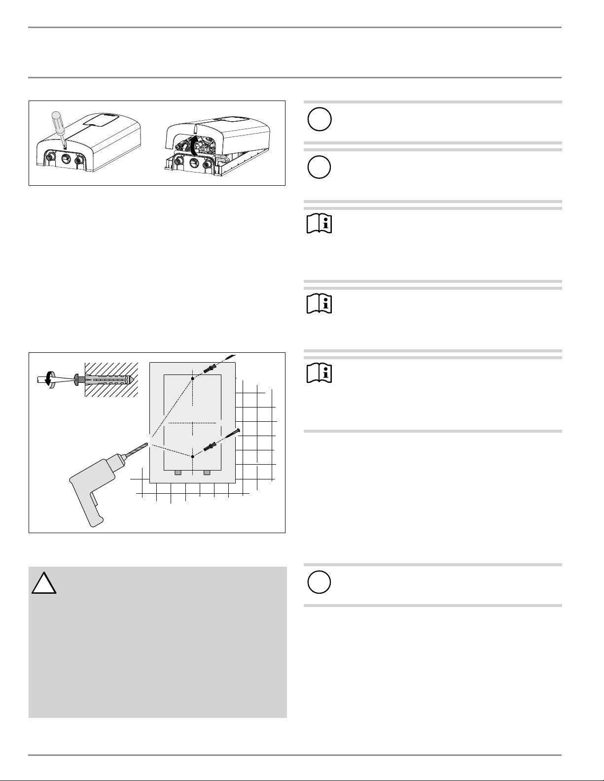
INSTALACIÓN
Instalación
40 | DHX Trend y DHX Plus www.stiebel-eltron-usa.com
D0000094555-b
f Marque los 2 agujeros de perforación, refiriéndose a su po-
sición usando el panel trasero del calentador de agua como
guía.
f Ponga el panel trasero del calentador de agua a un lado y tala-
dre los 2 agujeros marcados.
f Instale los anclajes de pared en la pared, luego inserte y aprie-
te cada tornillo de montaje parcialmente. Se proporcionan tor-
nillos y anclajes de pared de plástico para el montaje en pared
de yeso o madera.
f Cuelgue la unidad en los 2 tornillos de montaje, asegurándose
de que la parte trasera de la unidad esté a ras de la pared.
f Una vez que la unidad esté en posición, 0 firmemente en la
pared apretando completamente los 2 tornillos de montaje.
D0000089951-a
11.2 Conexiones de agua
!
PRECAUCIÓN: NO INSTALE EL CALENTADOR DENTRO DE
UNA MAMPARA DE BAÑO O MAMPARA DE DUCHA NI
LO CONECTE A UN ABLANDADOR DE AGUA DE SAL
REGENERANTE O A UN SUMINISTRO DE AGUA SALADA.
PARA USO EN UN CIRCUITO DE RAMA INDIVIDUAL SOLA-
MENTE
PRECAUCIÓN: CONECTAR SOLO A UN CIRCUITO PRO-
TEGIDO POR UN INTERRUPTOR DIFERENCIAL CLASE A
USE SÓLO CONDUCTORES DE COBRE
USE EL CONDUCTOR DE UNIÓN ADECUADO SEGÚN EL CÓDI-
GO ELÉCTRICO CANADIENSE, PARTE I
!
Pérdidas materiales
Realice todos los trabajos de conexión e instalación de agua
respetando la normativa.
!
Pérdidas materiales
El calor excesivo de la soldadura de tuberías de cobre cerca
del DHX puede dañar la unidad o la malla de filtro de plás-
tico ubicada en la entrada de agua fría.
AVISO
Usted DEBE desconectar la conexión de agua fría que ingre-
sa a la unidad de manera periódica para limpiar la malla de
filtro. Se requiere el uso de conexiones de agua que sean
fácilmente desmontables, como los conectores flexibles de
acero trenzado.
AVISO
Las aguas duras o con un alto recuento de minerales pue-
den dañar la unidad. La garantía no cubre los daños a la
unidad causados por incrustaciones o un alto recuento de
minerales.
AVISO
Los calentadores de agua sin tanque como el DHX no re-
quieren válvulas de alivio de temperatura y presión (T&P).
Si el inspector local no aprobara la instalación sin una T&P,
esta debe instalarse al lado de la salida de agua caliente
de la unidad.
11.2.1 Materiales de conexión de agua permitidos
f La salida de agua caliente del DHX (izquierda) está diseñada
para conectarse a un tubo de cobre, un tubo PEX o una man-
guera trenzada de acero inoxidable con una rosca cónica hem-
bra NPT de ½ pulg.
f La tubería de la entrada de agua fría (derecha) debe ser tal que
se pueda quitar fácilmente para permitir el acceso a la malla
de filtro de entrada. La forma más fácil de lograr esto es usar
un conector flexible de acero trenzado con una conexión hem-
bra NPT de ½ pulg.
!
Pérdidas materiales
Si se utilizan tuberías de plástico, tenga en cuenta la tempe-
ratura máxima de entrada y la presión máxima permitidas.
11.2.2 Velocidad de flujo
f Si no se alcanza la velocidad de flujo mínima para la activación
cuando la válvula de salida está completamente abierta, au-
mente la presión de la línea de agua.
f La presión mínima de la línea de suministro de agua fría en-
trante debe ser de al menos 26.1 psi (1.8 bar).
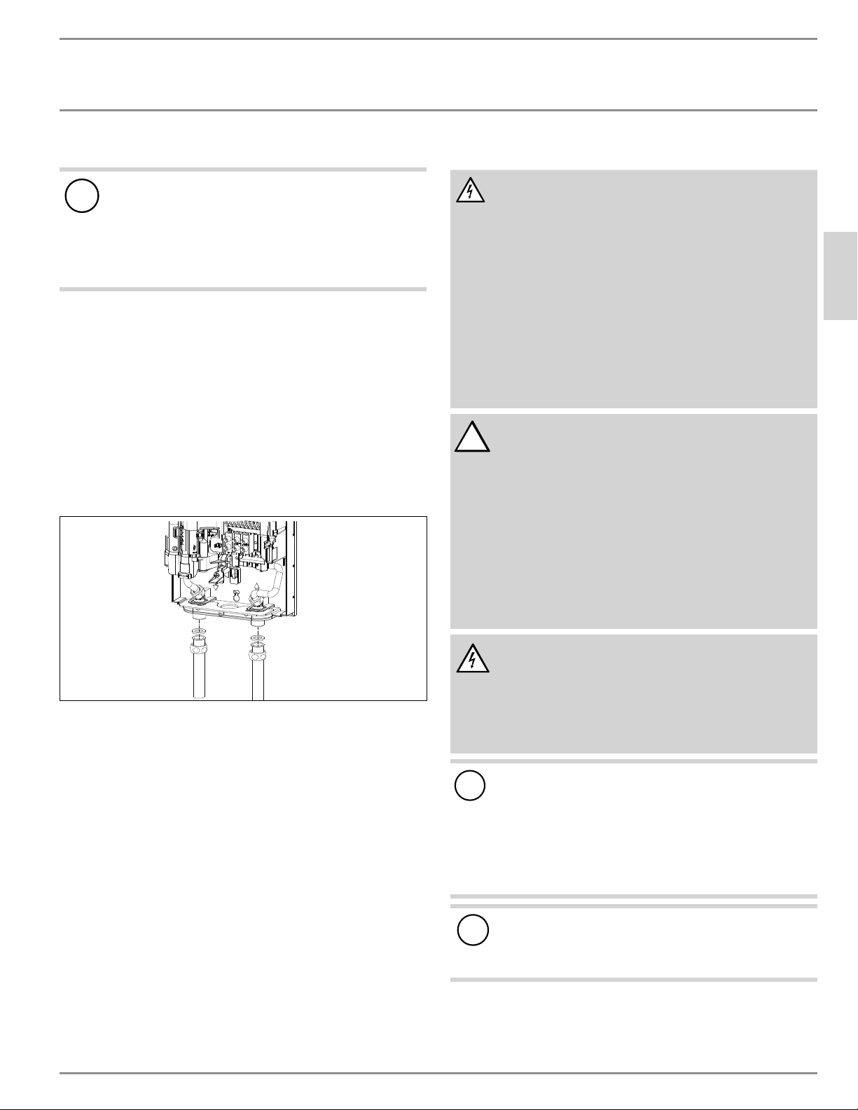
INSTALACIÓN
Instalación
ESPAÑOL
www.stiebel-eltron-usa.com DHX Trend y DHX Plus | 41
11.2.3 Instrucciones para las conexiones del agua
!
Pérdidas materiales
Si es necesario soldar cerca de la unidad, por favor dirija
la llama lejos de la carcasa de la unidad para evitar daños.
Tenga en cuenta que el calor excesivo de las soldaduras
(no recomendado) cerca del accesorio de entrada de agua
fría puede dañar la malla de plástico del filtro situada en
su interior.
Todo trabajo de fontanería debe cumplir con los códigos de fonta-
nería nacionales y estatales aplicables.
La conexión de agua fría (entrada) está en el lado derecho de la uni-
dad, la conexión de agua caliente (salida) está en el lado izquierdo
de la unidad.
f Debe instalarse una válvula reductora de presión si la presión
del suministro de agua fría supera los 10 bares (150 psi).
f Asegúrese de que la línea de suministro de agua fría se haya
enjuagado para eliminar cualquier cal y suciedad.
f Instale la válvula de cierre en la línea de agua fría como se
muestra en la ilustración de la página 39. Esto permite aislar
fácilmente la unidad para fines de mantenimiento.
D0000094555-b
f Conecta los conectores flexibles de acero trenzado (reco-
mendados para la salida caliente, requeridos para la entrada
fría, no suministrados) a los conectores macho NPT gemelos
½pulg.
f Abrir la válvula de cierre en la línea de entrada de agua fría.
f Cuando todos los trabajos de plomería estén terminados, com-
pruebe si hay fugas y tome las medidas correctivas antes de
proceder.
11.3 Instalación del aireador en el grifo conectado
El DHX 3.5-1 Trend se suministra con un reductor/aerador de flujo de
compensación de presión de 0.5 gpm (1.9 l/min). El DHX 6-2 Trend
se suministra con un reductor/aerador de flujo de compensación
de presión de 1.0 gpm (3.8 l/min). El aireador debe instalarse en el
grifo al que está conectado el calentador de agua. Si no se instala el
aireador, la temperatura del agua puede ser inferior a la deseada.
11.4 Conexión eléctrica
ADVERTENCIA Electrocución
Antes de comenzar cualquier trabajo en la instalación
eléctrica, asegúrese de que los interruptores del panel
principal de interruptores estén en la posición “Off”
para evitar cualquier peligro de descarga eléctrica.
Antes de proceder con la conexión eléctrica, se debe
completar el montaje y la plomería. Cuando así lo exijan
los códigos eléctricos locales, estatales o nacionales, los
circuitos deben contar con un “interruptor diferencial”.
La unidad debe estar correctamente conectada a tierra
de acuerdo con los códigos estatales y locales o, en
ausencia de dichos códigos, de acuerdo con el código
eléctrico nacional o el código eléctrico canadiense. Si
el producto no se conecta a tierra, se pueden producir
lesiones personales graves o la muerte.
!
PRECAUCIÓN: NO INSTALE EL CALENTADOR DENTRO DE
UNA MAMPARA DE BAÑO O MAMPARA DE DUCHA NI
LO CONECTE A UN ABLANDADOR DE AGUA DE SAL
REGENERANTE O A UN SUMINISTRO DE AGUA SALADA.
PARA USO EN UN CIRCUITO DE RAMA INDIVIDUAL SOLA-
MENTE
PRECAUCIÓN: CONECTAR SOLO A UN CIRCUITO PRO-
TEGIDO POR UN INTERRUPTOR DIFERENCIAL CLASE A
USE SÓLO CONDUCTORES DE COBRE
USE EL CONDUCTOR DE UNIÓN ADECUADO SEGÚN EL CÓDI-
GO ELÉCTRICO CANADIENSE, PARTE I
ADVERTENCIA Electrocución
Solo se permite una conexión permanente a la fuente de
alimentación usando el pasa cables extraíble. Asegúrese
de que el calentador de agua esté separado de la fuente
de alimentación mediante un interruptor aislador que
desconecte todos los polos con una separación de con-
tacto de al menos 1/8 pulg. (3 mm).
!
Alimente este aparato solo desde un sistema conectado
a tierra. Se proporciona un terminal verde (o un conector
de cable marcado “G”, “GR”, “GROUND” O “GROUNDING”)
para el cableado del aparato. Para reducir el riesgo de
descarga eléctrica, conecte este terminal o conector al
terminal de conexión a tierra del servicio eléctrico o
panel de suministro con un cable de cobre continuo de
acuerdo con el código de instalación eléctrica.
!
Pérdidas materiales
Respete la placa de identificación. El voltaje nominal es-
pecificado debe coincidir con el voltaje de la línea de su-
ministro.
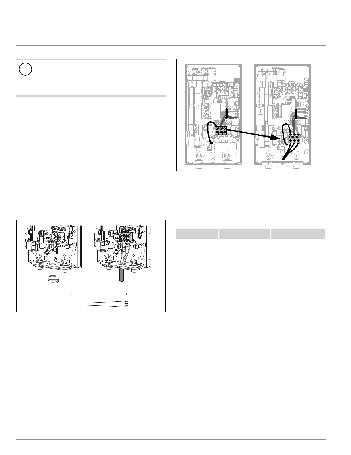
INSTALACIÓN
Puesta en marcha
42 | DHX Trend y DHX Plus www.stiebel-eltron-usa.com
!
Pérdidas materiales
El DHX 3.5-1 Trend sólo debe ser conectado a un suministro
eléctrico de 120 V. Si se conecta el DHX 3.5-1 Trend a un
suministro eléctrico de 208-240 V, se dañará permanente-
mente la unidad y se anulará la garantía de fábrica.
f Todos los trabajos eléctricos deben cumplir con los códigos
eléctricos nacionales y estatales aplicables.
f El DHX debe ser conectado a un circuito dedicado de deriva-
ción debidamente conectado a tierra y con el voltaje adecua-
do. En instalaciones con varias unidades DHX, cada unidad
requiere un circuito independiente. Consulte la tabla de datos
técnicos para conocer el tamaño correcto de los cables y los
disyuntores.
f En la abertura situada entre las conexiones de agua caliente y
fría debe instalarse una abrazadera Romex ¾ pulg. (requerida,
no suministrada). El cable debe ser alimentado a través de la
abrazadera Romex. Los cables “vivos” deben conectarse a las
ranuras del bloque de terminales marcado con la N y la L (DHX
3.5-1 Trend solamente) o la L y la L (todas las demás versiones).
El cable de tierra debe conectarse a la ranura marcada con el
símbolo de tierra. Consulte la sección 17.2, “Diagramas de ca-
bleado”, pág. 48.
4Ǭ–5ǩÝ (125–130 mm)
D0000089948-a
11.5 Conexión eléctrica con un cable de alimentación
corto
Si el cable de alimentación no es lo suficientemente largo, puede
instalar el bloque de cables más cerca de la abertura en el calen-
tador de agua.
f Reposiciona el bloque de cableado de arriba a abajo. Para ello,
desengánchelo empujándolo firmemente hacia la izquierda y
tirando de él hacia adelante.
D0000095302-b
f Enganche el bloque de cableado en la parte inferior empuján-
dolo hacia adentro y hacia la izquierda hasta que encaje en su
lugar.
11.6 Bloque de cableado
Consulte la tabla de abajo para conocer las cantidades de par de
torsión recomendadas en los tornillos del bloque de cableado.
Tamaño del
tornillo (mm)
Torsión mínima
(N•cm)
Torsión mínima (lbf•in)
M6 200–250 17.7–22.1
Usar las especificaciones de torsión adecuadas para asegurar el
cable al bloque de cableado ayuda a evitar pérdidas personales o
daños a la propiedad.
12. Puesta en marcha
12.1 Protección interna anti-escaldadura a través de
la ranura de puente
Para mayor seguridad, el contratista cualificado puede establecer un
límite interno de temperatura anti escaldadura a través del puente
“T
max
”. La función de protección anti-escaldadura limita la tempe-
ratura máxima de salida del calentador de agua. Esta característica
anula la pantalla de ajuste de la temperatura en la cubierta frontal
(tanto la selección de la temperatura como el límite de temperatura
a través de las funciones de software). El usuario puede seguir ha-
ciendo ajustes de temperatura por debajo del límite antiquemaduras
utilizando la pantalla, sin embargo, cualquier temperatura selec-
cionada que sea superior al límite T
max
establecido será ignorada,
y la temperatura de salida se limitará al valor T
max
.
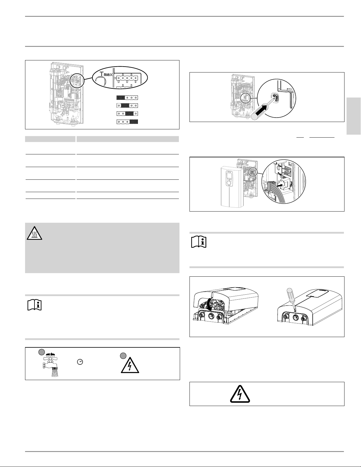
INSTALACIÓN
Puesta en marcha
ESPAÑOL
www.stiebel-eltron-usa.com DHX Trend y DHX Plus | 43
38°C | 100°F
43°C | 109°F
50°C | 122°F
60°C | 140°F
D0000094558-b
Posición de puente Descripción
38 °C | 100 °F Aplicaciones de lavado de manos conformes con
el código (configuración de fábrica)
43 °C | 109 °F Aplicaciones en las que el riesgo de quemadu-
ras puede ser una preocupación
50 °C | 122 °F Agua caliente para el fregadero de la cocina,
fregadero de servicio, etc.
60 °C | 140 °F Aplicaciones comerciales (cocinas, etc.), requisi-
tos del código de salud
Sin puente Límite 38 °C | 100 °F
f Instale el puente en la posición requerida en la tira de clavijas
“T
max
”.
PRECAUCIÓN Quemaduras
Si el agua suministrada al calentador de agua se preca-
lienta, la protección interna antiquemaduras y el límite
de temperatura ajustable por el usuario pueden ser su-
perados.
En tales casos, limite la temperatura con una válvula ter-
mostática central aguas arriba.
12.2 Puesta en marcha inicial
Nota
Durante la puesta en marcha inicial, DEBE activar el inte-
rruptor de seguridad AE3 presionando el botón de reinicio
blanco antes de suministrar energía al calentador de agua.
La unidad NO funcionará hasta que el interruptor de segu-
ridad no esté activado.
PLQ
1
2
Abra el
grifo
Encienda la
fuente de
alimenta-
ción.
D0000053277
f Abra y cierre todas las válvulas de salida conectadas al menos
cinco veces en total. Deje correr el agua durante al menos tres
minutos, hasta que se haya purgado todo el aire de la tubería y
el calentador de agua.
f Asegúrese de que no haya fugas de agua en ninguna conexión
de las tuberías.
12.2.1 Activación inicial del interruptor de seguridad AE3
D0000094561-b
f Active el interruptor de seguridad AE3 presionando firmemente
el botón blanco de reinicio hasta que haga clic y se bloquee
completamente en su lugar (el calentador de agua se entrega
con el interruptor de seguridad desactivado).
D0000082937
f Conecte el enchufe del cable de la unidad de programación a
la PCI.
Nota
Es esencial enchufar el cable de conexión de la unidad de
programación a la PCI antes de encenderlo. De lo contrario,
la unidad de programación no funcionará.
D0000073642
f Enganche la cubierta en la parte superior de la tapa trasera del
calentador de agua. Empuje la tapa hacia abajo. Verifique que
la cubierta esté bien asentada en las partes superior e inferior.
f Asegure la cubierta con el tornillo.
f Retire la película protectora del panel frontal.
Encienda la fuente
de alimentación.
D0000053281
f Encienda la fuente de alimentación.
f Asegúrese de que la unidad de programación funciona
correctamente.
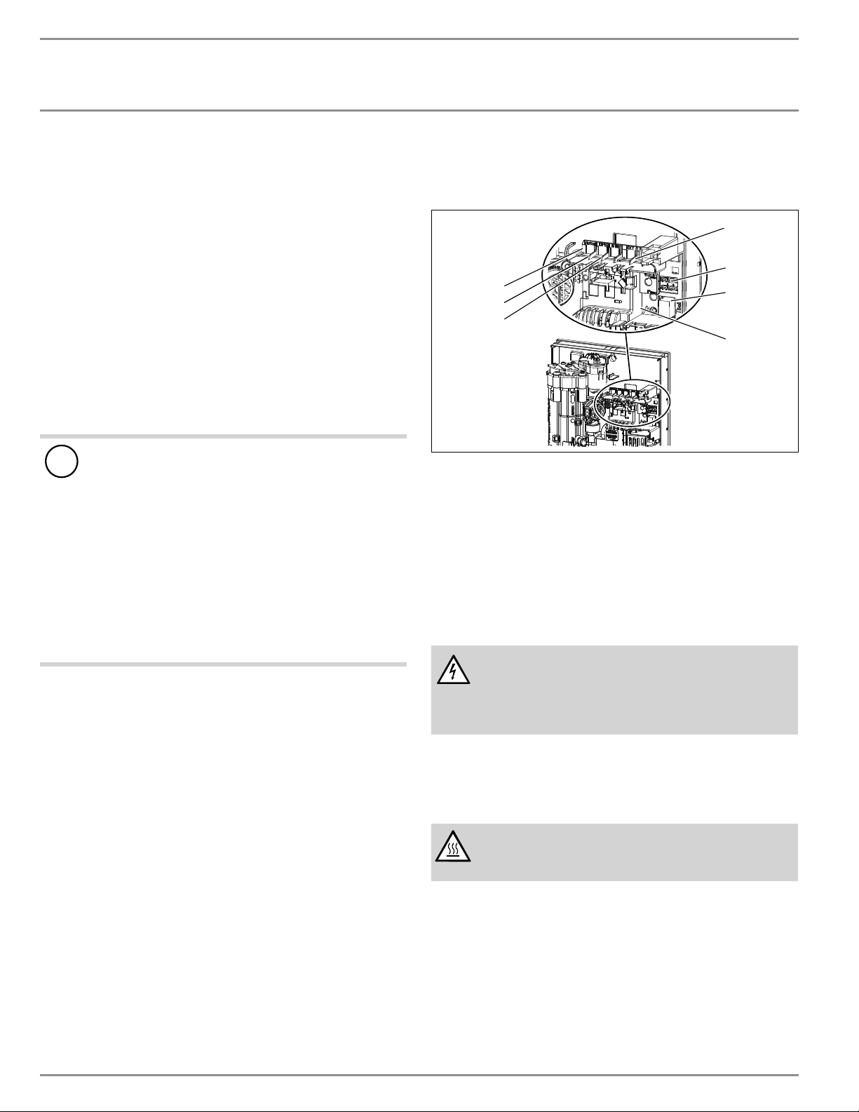
INSTALACIÓN
Apagado del calentador de agua
44 | DHX Trend y DHX Plus www.stiebel-eltron-usa.com
12.2.2 Entrega del calentador de agua
f Explique el funcionamiento del calentador de agua a los usua-
rios y permítales familiarizarse con su funcionamiento.
f Informe a los usuarios sobre los peligros potenciales, especial-
mente el riesgo de quemaduras.
f Entregue las instrucciones.
12.3 Operación con agua precalentada
Puede limitar la temperatura máxima de entrada instalando una
válvula termostática central.
Use una válvula termostática para la pre mezcla central, por ejem-
plo, cuando opere un calentador de agua instantáneo con agua
precalentada. Para usar en la ducha, la válvula debe ajustarse a un
máximo de 131 °F (55 °C).
12.4 Reinicio
!
Pérdidas materiales
Para garantizar que el sistema de calentamiento en espiral
no se dañe después de una interrupción en el suministro
de agua, el calentador de agua debe reiniciarse siguiendo
los siguientes pasos:
f Apague la alimentación de la unidad desde el panel de
interruptores, asegurándose de que los interruptores
de circuito conectados estén en la posición “OFF” para
evitar cualquier peligro de descarga eléctrica.
f Abra y cierre el grifo al menos cinco veces durante tres
minutos en total, hasta que el calentador de agua y su
línea de entrada de agua fría estén libres de aire.
f Vuelva a conectar la alimentación en el panel de inte-
rruptores.
13. Apagado del calentador de agua
f Apague la alimentación de la unidad desde el panel de inte-
rruptores, asegurándose de que los interruptores de circuito
conectados estén en la posición “OFF” para evitar cualquier
peligro de descarga eléctrica.
f Drene el calentador de agua (Consulte la sección 15.1, “Drenaje
del calentador de agua”, pág. 44").
14. Información para servicio técnico
Estado de conexiones/Estado de componentes
1
2
3
5
6
7
4
D0000095301-a
1 Válvula motorizada
2 Sensor de flujo
3 Corte de seguridad por exceso del límite de temperatura, reini-
cio automático, Klixon
4 NTC sensor
5 Alojamiento de cables y cabecera para carga conectada y ajus-
te de temperatura
6 Enchufe de la unidad de programación
7 Luces de diagnóstico
15. Mantenimiento
ADVERTENCIA Electrocución
Antes de comenzar cualquier trabajo en el calentador de
agua, asegúrese de que los disyuntores conectados estén
“apagados” para evitar cualquier peligro de descarga
eléctrica.
15.1 Drenaje del calentador de agua
El calentador de agua se puede drenar para realizar trabajos de
mantenimiento.
ADVERTENCIA Quemaduras
Al drenar el calentador de agua, es posible que se escape
agua caliente.
f Cierre la válvula de la línea de entrada de agua fría.
f Abra todas las válvulas de salida.
f Desconecte las conexiones de agua del calentador de agua.
f Guarde el calentador de agua desmontado en un lugar donde
no haya riesgo de escarcha, ya que los residuos de agua que
quedan dentro del calentador de agua pueden congelarse y
causar daños.
INSTALACIÓN
Mantenimiento
ESPAÑOL
www.stiebel-eltron-usa.com DHX Trend y DHX Plus | 45
15.2 Limpieza de la malla del filtro
ADVERTENCIA Quemaduras
Al drenar el calentador de agua, es posible que se escape
agua caliente.
!
Pérdidas materiales
Para garantizar que el sistema de calentamiento en espiral
no se dañe después de una interrupción en el suministro
de agua, el calentador de agua debe reiniciarse siguiendo
los siguientes pasos:
f Apague la alimentación de la unidad desde el panel de
interruptores, asegurándose de que los interruptores
de circuito conectados estén en la posición “OFF” para
evitar cualquier peligro de descarga eléctrica.
f Abra y cierre el grifo al menos cinco veces durante tres
minutos en total, hasta que el calentador de agua y su
línea de entrada de agua fría estén libres de aire.
f Vuelva a conectar la alimentación en el panel de inte-
rruptores.
El DHX tiene una malla de filtro de sedimentos incorporada que debe
limpiarse periódicamente.
f Apague el interruptor para desconectar la alimentación del
calentador de agua.
f Cierre la válvula de cierre para cortar el suministro de agua al
calentador de agua.
f Abra un grifo de agua caliente conectado para reducir la pre-
sión acumulada (esto minimizará las fugas al retirar la cone-
xión de la entrada de agua fría).
f Desconecte el conector flexible de acero trenzado del accesorio
de entrada de agua fría (derecha).
f Para quitar la malla de filtro de la parte inferior de la entrada
de agua fría, inserte con cuidado un destornillador de cabeza
plana justo por encima del borde de plástico de la malla de fil-
tro y tire suavemente hacia abajo.
f Limpie la malla de filtro, vuelva a insertarla de manera segura
en el accesorio de entrada de agua fría y vuelva a conectar el
conector flexible de acero trenzado a la entrada de agua fría.
f Abra la válvula de cierre del suministro de agua fría.
f Abra el grifo de agua caliente durante unos minutos para sacar
el aire de las tuberías y el calentador de agua. Mantenga el
grifo abierto hasta que el flujo de agua sea continuo y se haya
purgado todo el aire de las tuberías de agua.
f Encienda el interruptor para llevar energía eléctrica a la
unidad.
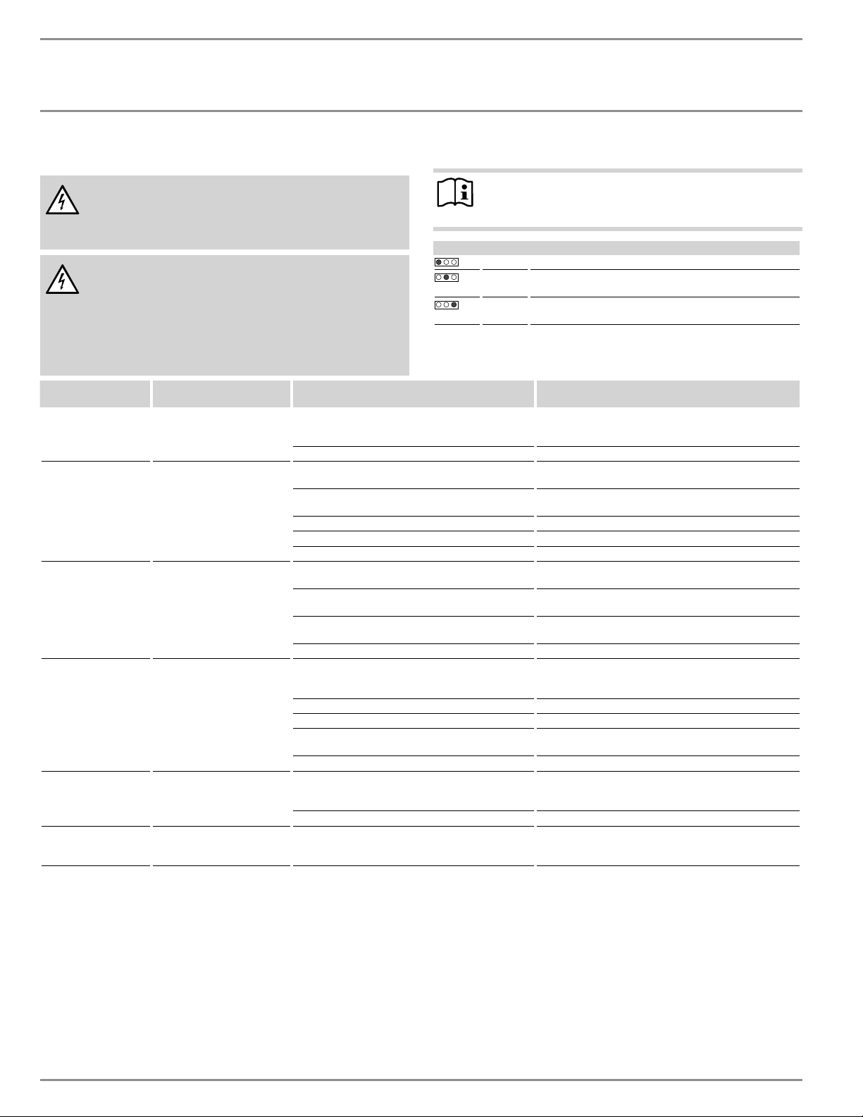
INSTALACIÓN
Resolución de problemas
46 | DHX Trend y DHX Plus www.stiebel-eltron-usa.com
16. Resolución de problemas
ADVERTENCIA Electrocución
Nunca quite o reinstale la cubierta del calentador de agua
sin cortar la electricidad que da servicio a la unidad. De lo
contrario, podría sufrir lesiones personales o la muerte.
ADVERTENCIA Electrocución
Para probar el calentador de agua con las luces de diag-
nóstico internas, este debe estar conectado a la fuente
de alimentación.
Si realiza la prueba sin la cubierta, no toque ninguna
parte del calentador de agua. Hacerlo podría provocar
lesiones personales graves o la muerte.
Nota
Para probar el calentador de agua con las luces de diag-
nóstico, el agua debe estar fluyendo a través de la unidad.
Luces de diagnóstico
Roja Se ilumina en caso de falla
Amarilla Se ilumina en modo calentamiento./Parpadea cuando se
alcanza el límite de salida
Verde Parpadea cuando el calentador de agua está conectado a la
fuente de alimentación.
Luces de
diagnóstico
Problema Causa Solución
Ninguna LED encendida El calentador de agua no
calienta
No hay electricidad
Verifique el disyuntor conectado en el panel del disyuntor
principal no se haya disparado. Restablecer si es nece-
sario
La PCI no funciona correctamente Reemplace la PCI
Verde intermitente,
amarilla apagada, roja
apagada
No hay ACS
La regadera/El aireador tiene incrustaciones Desincruste o reemplace la regadera/el aireador si es
necesario
La malla de filtro de la entrada de agua fría está
sucia
Limpie la malla de filtro. Consulte la sección 15.2, “Lim-
pieza de la malla del filtro”, pág. 45
El sensor de flujo no está conectado Conecte el cable a la PCI
El sensor de flujo no funciona correctamente Reemplace el sensor de flujo
La PCI no funciona correctamente Reemplace la PCI
Verde intermitente,
amarilla encendida,
roja apagada
La pantalla de la unidad de
programación está apagada
Hay un cable suelto entre la PCI y la unidad de pro-
gramación.
Compruebe el cable y conéctelo a la unidad de programa-
ción y/o al PCI
El cable de la unidad de programación no funciona
correctamente
Revise el cable y cámbielo si es necesario.
La PCI de la unidad de programación no funciona
correctamente
Reemplazar la unidad de programación, sólo disponible
con una nueva cubierta del calentador
La PCI no funciona correctamente Reemplace la PCI
Verde intermitente,
amarilla encendida,
roja apagada
La temperatura de salida no
coincide con el valor esta-
blecido
La unidad de programación no estaba enchufada
antes de encenderla
Reinicie apagando la alimentación eléctrica del calenta-
dor de agua
El sensor de salida no funciona correctamente Reemplace el sensor de salida
El grifo no funciona correctamente Reemplace el grifo
El sistema de calentamiento no funciona correcta-
mente
Reemplace el sistema de calentamiento
La PCI no funciona correctamente Reemplace la PCI
Sólo para los modelos
Plus: Verde parpadean-
te, amarillo parpadean-
La temperatura de salida no
coincide con el valor esta-
blecido
Se alcanzó el límite motorizado de la válvula
Reduzca la temperatura establecida
te, rojo apagado La válvula motorizada no funciona correctamente Reemplace la válvula motorizada
Verde intermitente,
amarilla apagada, roja
encendida
No hay agua caliente
Se detectó la presencia de aire
Continúe con la extracción durante > 1 minuto
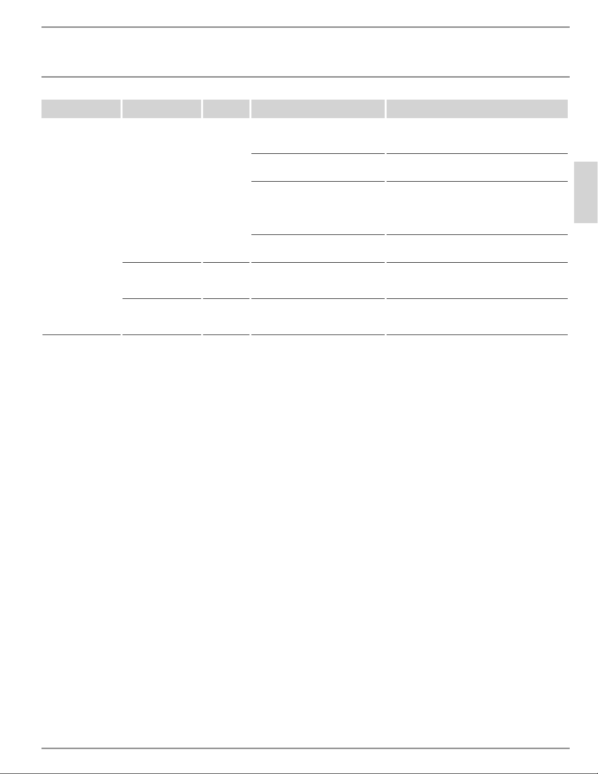
INSTALACIÓN
Resolución de problemas
ESPAÑOL
www.stiebel-eltron-usa.com DHX Trend y DHX Plus | 47
Luces de
diagnóstico
Pantalla de lectura Problema Causa Solución
Sólo para los modelos
Plus: verde intermitente,
amarilla apagada, roja
encendida
Hay una llave que parpa-
dea (el menú “Fault code
display” muestra E1 y
la llave)
No hay ACS
El interruptor de seguridad AE3 no fue ac-
tivado durante la puesta en marcha
Active el interruptor de seguridad AE3 presionando fir-
memente el botón de reinicio. Consulte la sección 12.2.1,
“Activación inicial del interruptor de seguridad AE3”, pág.
43
El interruptor de seguridad AE3 se disparó
por corte de seguridad por exceso del
límite de temperatura, Klixon
Verifique el corte de seguridad por exceso del límite de
temperatura (conexión de enchufe, cable de conexión);
active el interruptor de seguridad AE3
El interruptor de seguridad AE3 se dispara
nuevamente después de que se haya ve-
rificado el corte de seguridad por exceso
del límite de temperatura; el corte de
seguridad por exceso del límite de tempe-
ratura no funciona correctamente
Reemplace el corte de seguridad por exceso del límite
de temperatura; active el interruptor de seguridad AE3
y extraiga el agua al valor máximo establecido durante
>1minuto
El interruptor de seguridad se dispara
nuevamente; la PCI no funciona correc-
tamente
Reemplace la PCI
Hay una llave que parpa-
dea (el menú “Fault code
display” muestra E2 y
la llave)
No hay ACS
La PCI no funciona correctamente (se
cortó algún cable o hay un cortocircuito
en el sensor de entrada)
Reemplace la PCI
Hay una llave que parpa-
dea (el menú “Fault code
display” muestra E3 y
la llave)
No hay ACS
Hay un cortocircuito en el sensor de salida
Verifique el sensor de salida, reemplácelo si es necesario
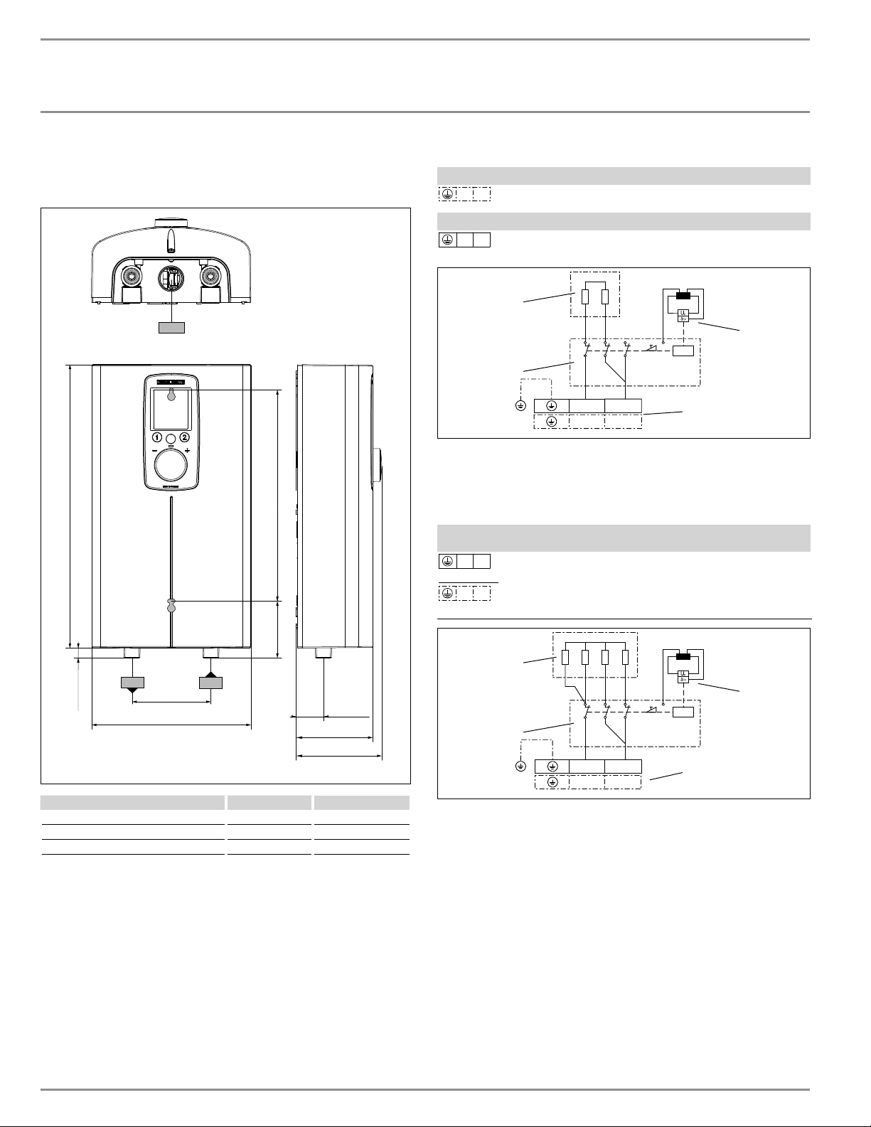
INSTALACIÓN
ńĤ¼êÐ|êēĉ
48 | DHX Trend y DHX Plus www.stiebel-eltron-usa.com
17. Especificación
17.1 Dimensiones y conexiones
c06 c01
c01
c06
b01
i
7
15
/
16
Ý (202)
1
3
/
8
Ý (35)
4
5
/
16
Ý(109)
1
9
/
16
Ý (40)
3
7
/
8
Ý (98)
14
3
/
16
Ý (360)
Agujeros de montaje, cubierta trasera
12
5
/
8
Ý (320)
½Ý (13)
3
15
/
16
Ý (100)
D0000094547-b
DHX
b02 Cables eléctricos de entrada
c01 Entrada de agua fría Rosca macho NPT de ½ pulg.
c06 Salida del ACS Rosca macho NPT de ½ pulg.
17.2 Diagramas de cableado
DHX 3.5-1 Trend
L N
1/Neutro/Tierra (GND) ~ 120 V
DHX 6-2 Trend
L L
2/Tierra (GND) ~ 208 / 240 V
N
L
L
L
D0000085463
1
3
4
2
1 PCI de potencia con interruptor de seguridad integral
2 Sistema de calentamiento en espiral
3 Corte de seguridad por exceso del límite de temperatura
4 Bloque de cableado
DHX 8-2 Trend | DHX 10-2 Trend | DHX 12-2 Trend & Plus
DHX 15-2 Trend & Plus
L L
2/Tierra (GND) ~ 208 / 240 V
L N
1/Neutro/Tierra (GND) ~ 208 / 240V
N
L
L
L
D0000077991
1
3
4
2
1 PCI de potencia con interruptor de seguridad integral
2 Sistema de calentamiento en espiral
3 Corte de seguridad por exceso del límite de temperatura
4 Bloque de cableado
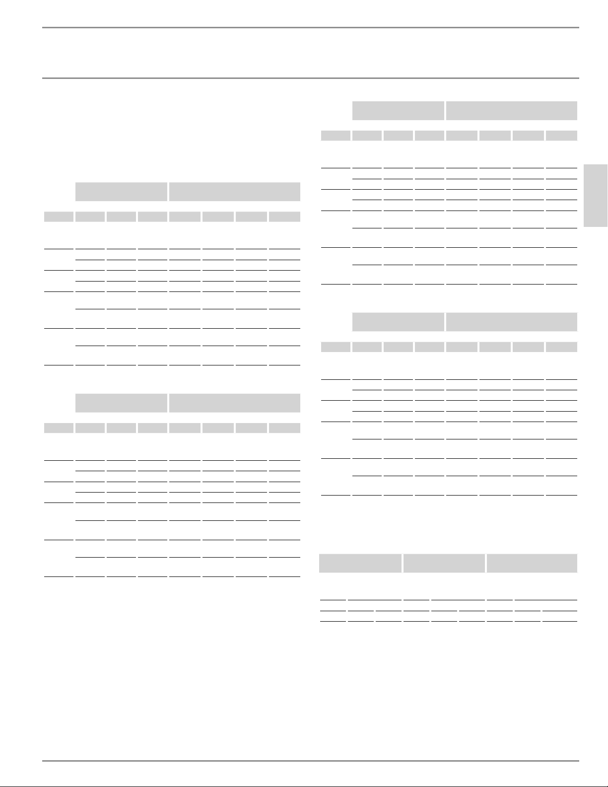
INSTALACIÓN
ńĤ¼êÐ|êēĉ
ESPAÑOL
www.stiebel-eltron-usa.com DHX Trend y DHX Plus | 49
17.3 Salida del ACS
La salida del ACS depende de la fuente de alimentación conecta-
da, la salida de potencia seleccionada del calentador de agua y la
temperatura de entrada del agua fría. El voltaje nominal y la salida
nominal se pueden encontrar en la placa de identificación.
Potencia de salida
en kW
100 °F DHW output in gpm
Tensión nominal Temperatura de entrada de agua fría
Modelo ĜŝƃŨp ŝƃÄŨp ŝÔƃŨp 41 °F 50 °F 59 °F 68 °F
DHX
3.5-1
Trend 3.5 0.41 0.48 0.58 0.75
DHX 8-2
Trend
5.4 0.63 0.74 0.9 1.15
7.2 0.83 0.98 1.2 1.54
DHX 10-2
Trend
7.2 0.83 0.98 1.2 1.54
9.6 1.11 1.31 1.6 2.05
DHX 12-2
Trend &
Plus
9.0 1.04 1.23 1.5 1.92
12.0 1.39 1.64 2.0 2.56
DHX 15-2
Trend &
Plus
10.8 1.24 1.46 1.78 2.28
14.4 1.67 1.97 2.4 3.07
Potencia de salida
en kW
122 °F DHW output in gpm
Tensión nominal Temperatura de entrada de agua fría
Modelo ĜŝƃŨp ŝƃÄŨp ŝÔƃŨp 41 °F 50 °F 59 °F 68 °F
DHX
3.5-1
Trend 3.5 0.3 0.33 0.38 0.44
DHX 8-2
Trend
5.4 0.46 0.51 0.59 0.68
7.2 0.61 0.68 0.78 0.91
DHX 10-2
Trend
7.2 0.61 0.68 0.78 0.91
9.6 0.81 0.91 1.04 1.21
DHX 12-2
Trend &
Plus
9.0 0.76 0.85 0.98 1.14
12.0 1.01 1.14 1.3 1.52
DHX 15-2
Trend &
Plus
10.8 0.9 1.02 1.16 1.35
14.4 1.21 1.37 1.56 1.82
Potencia de salida
en kW
38 °C DHW output in l/min
Tensión nominal Temperatura de entrada de agua fría
Modelo ĜŝƃŨp ŝƃÄŨp ŝÔƃŨp 5 °C 10 °C 15 °C 20 °C
DHX
3.5-1
Trend
3.5 1.5 1.8 2.2 2.8
DHX 8-2
Trend
5.4 2.3 2.8 3.4 4.3
7.2 3.1 3.7 4.5 5.7
DHX 10-2
Trend
7.2 3.1 3.7 4.5 5.7
9.6 4.2 4.9 6.0 7.6
DHX 12-2
Trend &
Plus
9.0 3.9 4.6 5.6 7.1
12.0 5.2 6.1 7.5 9.5
DHX 15-2
Trend &
Plus
10.8 4.6 5.5 6.6 8.5
14.4 6.2 7.3 8.9 11.4
Potencia de salida
en kW
50 °C DHW output in l/min
Tensión nominal Temperatura de entrada de agua fría
Modelo ĜŝƃŨp ŝƃÄŨp ŝÔƃŨp 5 °C 10 °C 15 °C 20 °C
DHX
3.5-1
Trend 3.5 1.1 1.3 1.4 1.7
DHX 8-2
Trend
5.4 1.7 1.9 2.2 2.6
7.2 2.3 2.6 2.9 3.4
DHX 10-2
Trend
7.2 2.3 2.6 2.9 3.4
9.6 3.0 3.4 3.9 4.6
DHX 12-2
Trend &
Plus
9.0 2.9 3.2 3.7 4.3
12.0 3.8 4.3 4.9 5.7
DHX 15-2
Trend &
Plus
10.8 3.4 3.8 4.4 5.1
14.4 4.6 5.1 5.9 6.9
17.4 Áreas de aplicación/tabla de conversión
Aquí, se muestran los datos de resistividad y conductividad eléctrica.
Especificación
estándar a 15 °C
20 °C
25 °C
Resis-
tividad
ρ≥
Conductividad
ı≤
Resis-
tividad
ρ≥
Conductividad
ı≤
Resis-
tividad
ρ≥
Conductividad ı≤
Ωcm mS/m μS/cm Ωcm mS/m μS/cm Ωcm mS/m μS/cm
1100 91 910 970 103 1031 895 112 1117
17.4.1 Caída de presión, cómo calcular el tamaño de la tubería
Para calcular el tamaño de la tubería, se recomienda una caída de
presión al calentador de agua de 14.5 psi (0.1 MPa).
17.5 Condiciones de falla
En caso de falla, durante la instalación pueden ocurrir brevemente
temperaturas de hasta 176 °F (80 °C) a una presión de 145 psi (1.0
MPa).
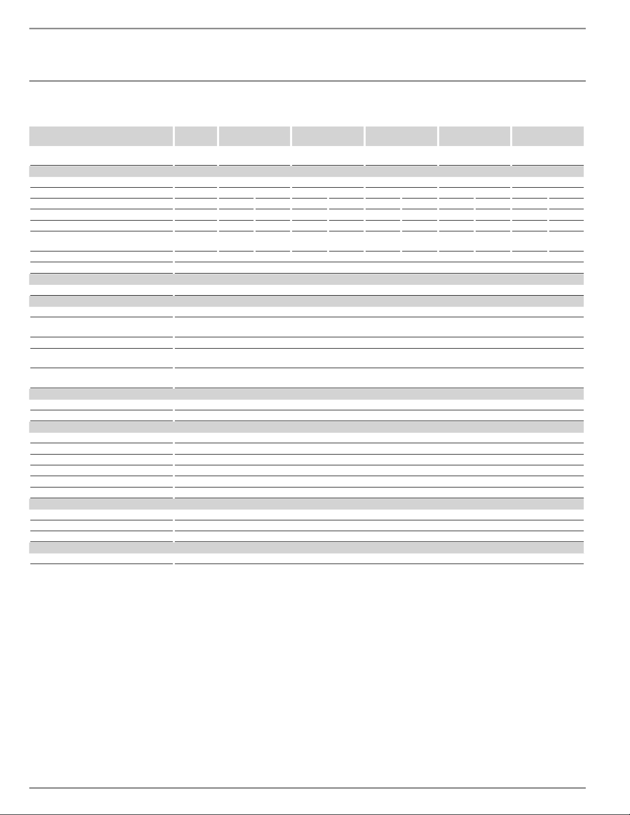
INSTALACIÓN
ńĤ¼êÐ|êēĉ
50 | DHX Trend y DHX Plus www.stiebel-eltron-usa.com
17.6 Tabla de datos
DHX 3.5-1
Trend
DHX 6-2 Trend DHX 8-2 Trend DHX 10-2 Trend DHX 12-2 Trend
DHX 12-2 Plus
DHX 15-2 Trend
DHX 15-2 Plus
Número de artículo 200067 203795 200068 200069 200070 (Trend)
200066 (Plus)
200071 (Trend)
202151 (Plus)
Datos eléctricos
Fase (50/60 Hz) 1/N/GND 1/N/GND | 2/GND 1/N/GND | 2/GND 1/N/GND | 2/GND 1/N/GND | 2/GND 1/N/GND | 2/GND
Tensión nominal 120 V 240 V 208 V 240 V 208 V 240 V 208 V 240 V 208 V 240 V 208 V
Salida nominal 3.5 kW 6.0 kW 4.5 kW 7.2 kW 5.4 kW 9.6 kW 7.2 kW 12.0 kW 9.0 kW 14.4 kW 10.8 kW
Corriente nominal 29.2 A 25 A 21.7 A 30 A 26 A 40 A 34.6 A 50 A 43.3 A 60 A 52 A
Tamaño de disyuntor recomendado
1
30 A 25 A 25 A 30 A 30 A 40 A 35 A 50 A 50 A 60 A 60 A
Tamaño mín. de cable recomendado
2
(AWG cobre)
10/2 AWG 10/2 AWG 10/2 AWG 10/2 AWG 10/2 AWG 8/2 AWG 8/2 AWG
8/2 AWG
8/2 AWG
6/2 AWG
6/2 AWG
Mín. resistividad ρ15 ≥ 1100 Ω cm
Máx. conductividad ı15 ≤ 910 μS/cm
Conexiones
Conexiones de agua NPT de ½ pulg.
Límites de aplicación
Presión máx. permisible 145 psi (1 MPa)
Temperatura máx. de entrada para reca-
lentar
131 °F (55 °C)
Temperatura máx. de entrada 149 °F (65 °C)
Rango de temperatura seleccionable por
el usuario
68–140 °F (20–60 °C)
Valores del limitador de temperatura de
protección anti-escaldadura interna
100/109/122/140 °F (38/43/50/60 °C)
Datos hidráulicos
Tasa de activación 0.264 gal (1.0 l/min)
Capacidad nominal 0.07 gal (0.277 l)
Versiones
Tipo de instalación Sobre el fregadero / bajo el fregadero
Clase de protección 1
Bloque aislante Poliamida reforzada con vidrio
Sistema de calentamiento Calentamiento en espiral
Cubierta y cubierta trasera Plástico
Color Blanco
Dimensiones
Altura 14
1
/
8
pulg. (360 mm)
Ancho 8 pulg. (202 mm)
Profundidad 4
5
/
16
pulg. (109 mm)
Pesos
Peso 5.5 lbs (2.5 kg)
DHX 3.5-1 Trend se suministra con una presión de 0.5 gpm (1.9 l/min) compensar reductor de flujo / aireador que se debe instalar.
DHX 6-2 Trend se suministra con una presión de 1.0 gpm (3.8 l/min) compensar reductor de flujo / aireador que se debe instalar.
1
Protección contra sobrecargas dimensionada al 100% de la carga. Los calentadores de agua sin tanque se consideran una carga no continua. Utilice solo disyuntores
para tomas GFCI Clase A.
2
Se deben utilizar conductores de cobre con una temperatura nominal de 75 °C o superior. Los conductores deben dimensionarse para mantener una caída de voltaje
de menos del 3 % bajo carga.
Estas son nuestras recomendaciones. Verifique los códigos locales si es necesario.
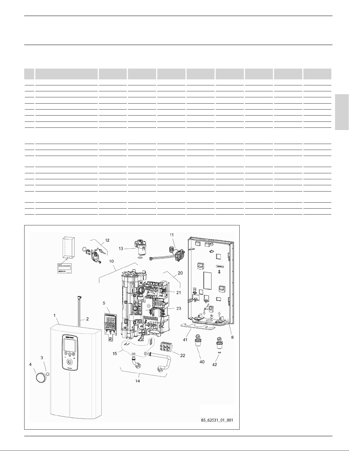
INSTALACIÓN
Repuestos
ESPAÑOL
www.stiebel-eltron-usa.com DHX Trend y DHX Plus | 51
18. Repuestos
No. Repuesto DHX 3.5-1
Trend
DHX 6-2
Trend
DHX 8-2
Trend
DHX 10-2
Trend
DHX 12-2
Trend
DHX 12-2
Plus
DHX 15-2
Trend
DHX 15-2
Plus
1 Cubierta (frente) 348149 348149 348149 348149 348149 348148 348149 348148
2 Cable de conexión de la PCI 158010 158010 158010 158010 158010 158010 158010 158010
3 Junta tórica 9.5x2 EPDM 269351 269351 269351 269351 269351 269351 269351 269351
4 Perilla de control 323686 323686 323686 323686 323686 323686 323686 323686
5 Pantalla LCD 349445 349445 349445 349445 349445 349333 349445 349333
8 Cubierta (atrás) 348144 348144 348144 348144 348144 348144 348144 348144
10 Sistema de calentamiento 344153 344154 344152 344152 344150 344147 344150 344147
11 Sensor de flujo 339979 339979 339979 339979 339979 339979 339979 339979
12
Corte de seguridad de alto límite
con autorreajuste, Klixon, con
sensor de salida
340528
340528
340528
340528
340528
340528
340528
340528
13 Válvula motorizada - - - - - 220502 - 220502
14 Conjunto de codo de tubo 340542 340542 340542 340542 340542 340542 340542 340542
15 Juego de conexión de codo de tu-
bería (incluye clips y juntas)
320540 320540 320540 320540 320540 320540 320540 320540
20 Placa electrónica de la PCI 348500 348501 348502 348503 348504 348498 348505 348499
21 Puente (rojo) 283455 283455 283455 283455 283455 283455 283455 283455
22 Bloque de cableado 326655 326655 326655 326655 326655 326655 326655 326655
23 Cubierta de electrónica 344146 344146 344146 344146 344146 344146 344146 344146
40 Conexiones de tubería (x2) -
½pulg.NPT / G⅜pulg.
326589 326589 326589 326589 326589 326589 326589 326589
41 Hoja de bloqueo 326234 326234 326234 326234 326234 326234 326234 326234
42 Malla de filtro 275981 275981 275981 275981 275981 275981 275981 275981
52 | DHX Trend y DHX Plus www.stiebel-eltron-usa.com
GUARANTEE
ENVIRONMENT AND RECYCLING
GARANTÍA | MEDIO AMBIENTE Y RECICLAJE
Esta garantía es válida sólo para EE.UU. y Canadá. Las garantías
pueden variar según el país. Por favor, consulte a su represen-
tante local de Stiebel Eltron para la garantía de su país.
Sujeto a los términos y condiciones expresados en esta
Garantía Limitada de por vida, Stiebel Eltron, Inc. (el
“Fabricante”) por la presente asegura al comprador
original (el “Propietario”) que cada calentador de agua
eléctrico de calor sin tanque (el “Calentador”) no deberá
(i) tener fugas debido a defectos en los materiales del
fabricante o mano de obra por un período de siete (7) años
desde la fecha de compra o (ii) falla debido a defectos
en los materiales o mano de obra del fabricante por un
período de tres (3) años a partir de la fecha de compra.
Como única y exclusiva solución para el Propietario en
cuanto a la presente garantía, el Fabricante, a discreción
del Fabricante, reparará en fábrica o reemplazará el
Calentador defectuoso con una unidad o repuesto
de reemplazo con características de funcionamiento
comparables. La máxima responsabilidad del Fabricante en
cualquier circunstancia se limitará al precio de compra del
Calentador que pagó el Propietario.
Esta garantía limitada será la garantía exclusiva que el
Fabricante otorga, y reemplaza todas las demás garantías,
expresas o implícitas, escritas u orales, que incluyen
pero no se limitan a las garantías de comerciabilidad
o adecuación para un fi n determinado. El Fabricante
no será responsable de daños incidentales, indirectos
o contingentes o gastos que surjan, de manera directa
o indirecta, de cualquier defecto del Calentador o del
uso del mismo. El Fabricante no será responsable por
daños ocasionados por el agua o cualquier otro daño a la
propiedad del Propietario que surja, de manera directa o
indirecta, de cualquier defecto del Calentador o del uso del
mismo. Solo el Fabricante está autorizado a conceder todas
las garantías en representación del Fabricante, y ninguna
declaración o garantía realizada por cualquier otra parte
será vinculante para el Fabricante.
El Fabricante no será responsable de ningún daño
relacionado o causado por:
1. cualquier uso indebido o falta de cuidado del
Calentador, cualquier accidente que afecte al
Calentador, cualquier alteración al Calentador, o
cualquier otro uso incorrecto;
2. casos fortuitos o circunstancias sobre las cuales el
Fabricante no tiene control;
3. instalación del Calentador que se desvíe de las
directivas del Fabricante o no observe los códigos de
construcción pertinentes;
4. negligencia en cuanto a mantener el Calentador u
operar el Calentador según las especifi caciones del
Fabricante;
5. hacer funcionar el Calentador en condiciones de presión
de agua fl uctuante o en caso de que el Calentador se
alimente de agua no potable durante un período de
cualquier duración;
6. instalación defectuosa y/o uso de materiales
inapropiados por parte de cualquier instalador y que no
se relacione con defectos en los repuestos o la mano de
obra del Fabricante;
7. mover el Calentador de su lugar original de instalación;
8. exposición a condiciones de congelamiento;
9. los problemas de calidad del agua, como el agua
corrosiva, el agua dura y agua contaminada con
contaminantes o aditivos;
Si el Propietario desea devolver el Calentador al Fabricante
para su reparación o reemplazo bajo esta garantía, el
Propietario debe obtener primero la autorización por
escrito del Fabricante. El Propietario deberá presentar una
prueba de compra, incluida la fecha de compra, y será
responsable de los costos de desinstalación y transporte. Si
el Propietario no puede demostrar una fecha de compra,
esta garantía se limitará al período que comienza a
partir de la fecha de compra impresa en el Calentador.
El Fabricante se reserva el derecho de negar la cobertura
de esta garantía después de examinar el Calentador. Esta
garantía se limita al Propietario y es intransferible.
Algunos Estados y Provincias no permiten la exclusión
o limitación de ciertas Garantías. En dichos casos, las
limitaciones aquí expresadas pueden no aplicarse al
Propietario. En dichos casos esta Garantía se limitará
al período más corto y las menores cifras de daños
permitidas por ley. Esta Garantía le da derechos legales
específi cos y puede que usted tenga otros derechos que
variarán de Estado a Estado y de Provincia a Provincia.
El Propietario será responsable de todos los costos
de mano de obra y otros cargos incurridos al retirar o
reparar el Calentador en el lugar de instalación. Por favor
obsérvese que el Calentador debe instalarse de tal manera
que, en caso de pérdida, el fl ujo de agua de la pérdida no
dañe el lugar en que está instalado.
!
La instalación, la conexión eléctrica y la primera opera-
ción de este aparato debe ser realizado por un calificado
instalador.
!
La empresa no se hace responsable de los fallos de los
bienes suministrados que no se hayan instalado y opera-
do de acuerdo con las instrucciones del fabricante.
Medio ambiente y reciclaje
Por favor, ayúdenos a proteger el medio ambiente eliminando el
embalaje de acuerdo con las regulaciones nacionales para el pro-
cesamiento de residuos.
19. Garantía

STIEBEL ELTRON, Inc.
17 West Street | West Hatfield MA 01088
Tel. 413-247-3380 | Fax 413-247-3369
www.stiebel-eltron-usa.com
A 344160-42759-9576
Subject to errors and technical changes! | ¡Sujeto a errores y cambios técnicos! |
Sous réserve d‘erreurs et de modifications techniques!