Loading ...
Loading ...
Loading ...
Controls and Operation
3
7
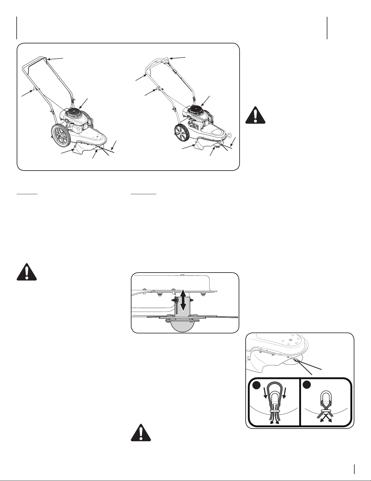
Controls
A. Recoil Starter
The recoil starter is attached to the right side of the
upper handle. Stand behind the unit and pull the
recoil starter rope to start the unit.
B. Engine Control Lever
The control lever must be depressed to start the
engine and rotation of trimmer spindle assembly.
Releasing the control lever stops the engine and
trimmer spindle assembly.
WARNING: This control lever is a safety
device. Never attempt to bypass its
operations.
C. Drive Control (If Equipped)
The drive control is located at the back of the upper
handle and is used to engage the drive. Squeeze
the control against the upper handle to engage the
drive; release it to slow down or stop the trimmer
from propelling.
D. Trimmer Deflector
The trimmer deflector is connected to the trimmer
base and it is used to prevent debris from being
thrown.
E. Spindle
The spindle rotates the trimmer line.
F. Trimmer Line
The trimmer line is attached to the spindle assembly
and it is used to trim grass, vegetation, undergrowth
and weeds.
G. Flywheel Screen
Keep the flywheel screen free of grass clippings and
debris at all times.
Engine Controls
See the Engine Operator’s Manual for the location
and function of the controls on the engine.
Operation
Adjusting the Spindle Height
The spindle height can be adjusted for various
applications. To do so, proceed as follows:
1. Loosen the wing nut found on each side of the
spindle shaft.
NOTE: The wing nuts are designed so that they
cannot be removed from the spindle shaft.
2. Slide the spindle upward or downward to the
desired position before retightening the wing
nuts. See Figure 3-2.
Figure 3-2
Starting and Stopping Engine
Refer to the Engine Operator’s Manual packed with
your string trimmer for instructions on starting and
stopping the engine.
Using Your String Trimmer
Be sure trimming area is clear of stones, sticks, wire,
or other objects which could damage the string
trimmer or engine. Such objects could be accidently
thrown by the trimmer in any direction and cause
serious personal injury to the operator and others.
WARNING: The operation of any string
trimmer can result in foreign objects
being thrown into the eyes, which can
damage your eyes severely. Always wear
safety glasses while operating the string
trimmer, or while performing any
adjustments or repairs on it.
A
B
D
E
F
G
A
B
C
D
E
F
G
260 Series
280 Series
(Handle styles and bumpers
may vary depending on model)
Figure 3-1
• The string trimmer is designed with the spindle
offset to the left side, allowing the operator to
trim along a fence, landscaping, or a house to
his or her’s right side without having to make
any adjustments to the machine.
• Operate the string trimmer at a slower walking
speed when trimming tall, thick weeds or grass.
• Clean the underside of the trimmer after each
use to remove any debris build up.
WARNING: Shut the engine off and wait
until the trimmer head comes to a
complete stop before cleaning the
discharge area. The trimmer head
continues to rotate for a few seconds after
the trimmer head control is released.
• Do not trim on excessively steep slopes. If a
slope is difficult to stand on, do not trim. Do
not trim on slopes when the ground is slippery
or wet. Trim across the face of a slope, not up
and down.
To use the Drive Control (if equipped):
• Once the engine is running, squeeze the drive
control lever against the upper handle to
propel the string trimmer.
• Release the single lever drive control to slow
down or stop the string trimmer from driving.
CAUTION: While operating the string trimmer, do not
allow the spindle to contact a concrete, asphalt, or
gravel surface. Doing so will result in premature wear.
Changing the Trimmer Line
To ease in removing worn trimmer line, change
the trimmer line before it becomes too short (i.e.
approximately half its original length).
1. Remove the worn trimmer line from the
spindle.
2. Fold the replacement trimmer line in half and
insert both ends through the loop near the
edge of the spindle.
3. Pull the ends of the trimmer line through the
loop until the line is securely beneath the
metal tab.
4. Cross the line ends and pull each tightly to
secure the trimmer line in place. See Figure 3-3.
1
2
Figure 3-3
NOTE: Always use 490-040-M035 trimmer
line. Refer to the separate supplement for
information on ordering.
Loading ...
Loading ...
Loading ...