Owner's Manual
iCRRFTSMRN°i
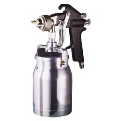
SPRAY GUN
Model No.
919.155310
• Safety Guidelines
• Operation
• Maintenance
• Storage
• Repair Parts
CAUTION: Read the Safety Guidelines
and All Instructions Carefully Before
Operating.
Sears, Roebuck and Co., Hoffman Estates, IL 60179 U.S.A.
Visit our Craftsman website: www.sears.com/craftsman
D28996 Rev0 03/21/03
Warranty .................... 2
Safety Guidelines .............. 3
Important Safety Rules ........ 3-4
Specifications ................ 4
General Information ............ 4
Operation .................. 4-5
Maintenance ................. 6
Troubleshooting ............... 7
Parts List .................... 8
How to Order Repair Parts ........
.................... back cover
lfl;1 :| :_;I_ hi"
FULL ONE YEAR WARRANTY
If this spray gun fails due to a defect in material or workmanship within one
year from the date of purchase, RETURN IT TO THE NEAREST SEARS
REPAIR CENTER THROUGHOUT THE UNITED STATES AND SEARS WILL
REPAIR IT,FREE OF CHARGE. If purchased from Orchard Supply Hardware,
return to the nearest Orchard Store and Orchard will repair it, free of charge.
If this spray gun is used for commercial or rental purposes, the warranty will
apply for ninety days from the date of purchase.
This warranty gives you specific legal rights and you may have other rights
which vary from state to state.
Sears, Roebuck and Co., Hoffman Estates, IL 60179 U.S.A.
[-_':I_l_li'd [ell]l)] _ II1_1:LL']m)]_l_lh i[o_]_.'-]
This manual contains information that is important for you to know and understand. This information
relates to protecting YOUR SAFETY and PREVENTING EQUIPMENT PROBLEMS, To help you
recognize this information_ we use the symbols below, Please read the manual and pay attention to
these sections.
SAFETY and PREVENTING EQUIPMENT PROBLEMS. To help you recognize this information, we
use the symbols befow, Please read the manual and pay attention to these sections,
_lndicates an
imminently hazardous
situation which, if not avoided, will
result in death or serious injury.
_lndicates a potentially
hazardous situation
which, if not avoided, could result in
death or serious injury.
_1'_llndicates a potentially
hazardous situation
which, if not avoided, _ result in
minor or moderate injury.
I_T_lUsed without the
safety alert symbol
indicates a potentially hazardous
situation which, if not avoided, may
result in oroDertv damaae.
D28996 2* ENG
• SAVE THESE INSTRUCTIONS •
IMPROPER OPERATION OR MAINTENANCE OF THIS PRODUCT
r '- _l;1,1Lll;L_ COULD RESULT IN SERIOUS INJURY AND PROPERTY DAMAGE. _l
READ AND UNDERSTAND ALL WARNINGS AND OPERATING INSTRUCTIONS BEFORE
USING THIS EQUIPMENT.
_The Following Hazards Can Occur During The Normal Use Of This Product:
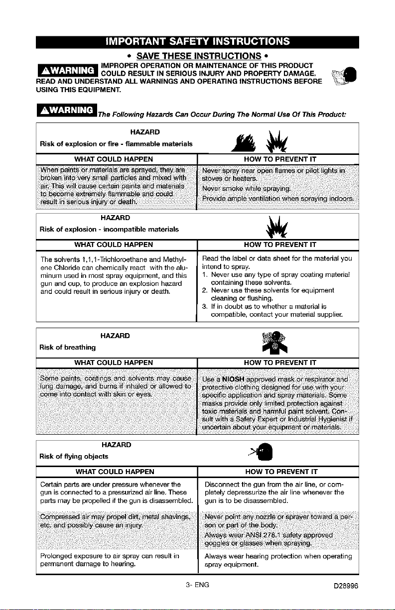
HAZARD
Risk of explosion or fire - flammable materials
WHAT COULD HAPPEN HOW TO PREVENT IT
HAZARD
Risk of explosion - incompatible materials
WHAT COULD HAPPEN HOW TO PREVENT IT
The solvents 1,1,1 _Trichleroethane and Methyl_ Read the label or data sheet for the material you
ene Chloride can chemically react with the alu- intend to spray.
minum used in most spray equipment, and this 1, Never use any type of spray coating materiat
gun &nd cup, to produce an explosion hazard containing these solvents.
and could result in serious injury or de_th, 2, Never use these solvents for equipment
cleaning or flushing.
3. If in doubt as to whether a m_terial is
compatible, contact your material supplier.
Risk of breathing HAZARD
WHAT COULD HAPPEN HOW TO PREVENT IT
HAZARD
Risk of flying objects "
WHAT COULD HAPPEN HOW TO PREVENT IT
Certain parts are under pressure whenever the
gun is connected to a pressurized air line, These
paris may be propelIed if the gun is disassembled.
Prolonged exposure to air spray can result in
permanent damage to hearing.
Disconnect the gun from the air line, or com-
pletely depressurize the air line whenever the
gun is to be disassembled.
Atways wear hearing protection when operating
spray equipment.
3* ENG D28996

HAZARD
Risk of injection _1_
WHAT COULD HAPPEN HOW TO PREVENT IT
[,,."]/,t_[_ ,o,T_lnl[[O_]j_[-,,.'-]
Air Inlet 1/4 NPS
Maximum Air Pressure 100 psi.
Recommended Operating Air Pressure 45 psi.
Cup 600 cc (20.29 oz)
I_T_ Before
disassembly or
removal of any part of gun or
attached components, shut off
compressor, release pressure
by depressing trigger, and
disconnect power source.
NEVER assume system pres-
sure is zero!
AN
EXPLOSIVE ATMOSPHERE,
WORK ONLY IN WELL-
VENTILATED AREAS.
USE OF A FACE
MASK IS
RECOMMENDED TO PREVENT
INHALATION OF TOXIC MATE-
RIAL.
[o]",,]=1-'_..,'tt [o]_j
DO NOT
ATTEMPT TO
UNCLOG (BACK FLUSH) SPRAY
GUN BY SQUEEZING TRIGGER
WHILE HOLDING FINGER IN
FRONT OF FLUID NOZZLE.
_ Pressure may
vary according
to viscosity of material used.
Maximum working pressure of
gun is 100 psi. DO NOT EXCEED
PRESSURE LIMIT OF GUN OR
ANY OTHER COMPONENT IN
SYSTEM!
Pp°rt°odn,a 2a ke
certain that all connections and
fittings are secure. Check hose
and all connections for a weak
or worn condition that could
render system unsafe. All re-
placement components such as
hose or fittings must have a
working pressure equal to or
greater than system pressure.
D28996 4* ENG
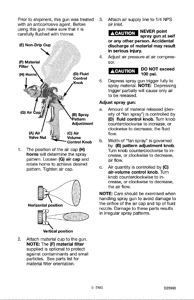
Prior to shipment, this gun was treated
with an anticorrosive agent. Before
using this gun make sure that it is
carefully flushed with thinner.
(E) Non-Drip Cup
(F) Material
(D) Fluid
Control
Knob
1.
(B) Spray
Adjustment
(C) Air
Valve Nut Volume
d Knob
The position of the air cap (H)
horns will determine the spray
pattern. Loosen (G) air cap and
rotate horns to achieve desired
pattern. Tighten air cap.
Horiz
3. Attach air supply line to 1/4 NPS
air inlet.
4.
NEVER point
spray gun at self
or any other person. Accidental
discharge of material may result
in serious injury.
Adjust air pressure at air compres-
sor.
DO NOT exceed
ILJ_J..._U.U,U_=
100 psi.
5.
Depress spray gun trigger fully to
spray material. NOTE: Depressing
trigger partially will cause only air
to be released.
Adjust spray gun:
a.
Amount of material released (den-
sity of "fan spray") is controlled by
(D) fluid control knob. Turn knob
counterclockwise to increase, or
clockwise to decrease, the fluid
flow.
b.
Width of "fan spray" is governed
by (B) pattern adjustment knob.
Turn knob counterclockwise to in-
crease, or clockwise to decrease,
air flow.
C.
Air quantity is controlled by (C)
air-volume control knob. Turn
knob counterclockwise to in-
crease, or clockwise to decrease,
the air flow.
NOTE: Care should be exercised when
handling spray gun to avoid damage to
the orifice of the air cap and tip of fluid
nozzle. Damage to these parts results
in irregular spray patterns.
2.
Vertical position
Attach material cup to the gun.
NOTE: The (F) material filter
supplied is optional to protect
against contaminants and small
particles. See parts list for
material filter orientation.
5* ENG D28996
I_1 Always exercise Lubrication
extreme care Lubrication procedures must be ob-
when using any solvent or thin-
ner. Never clean gun near fire,
flame, or any source of heat or
sparks. Properly dispose of
used cleaning materials.
DO NOT soak
entire spray gun
in solvent or thinner for a long
period of time as this will de-
stroy lubricants and possibly
make motion uneven. NEVER
use lye or caustic alkaline solu-
tion for cleaning. Such solutions
will attack aluminum alloy parts
of gun.
It is important that spray gun be
cleaned after daily use. Cleaning is ac-
complished by spraying appropriate
solvent or thinner through system.
Wipe exterior of spray gun with
solvent soaked cloth or use cleaning
brush(s) provided to remove any accu-
mulated material.
Cleaning
(a) Empty material from gravity feed
cup and replace with a suitable
solvent.
(b) Operate trigger until all material
traces have disappeared and gun
is thoroughly clean.
(c) Clean air cap with brush.
IMPORTANT: Make certain air cap
and fluid nozzle are kept clean at all
times. If necessary, remove these
two components and soak them in
solvent. DO NOT use hard objects
to clean clogged holes. The
smallest amount of damage may
cause irregular spray pattern.
NOTE: If fluid nozzle is to be re-
moved for thorough cleaning, squeeze
trigger to prevent damage of fluid
needle tip when unscrewing nozzle.
served after thoroughly cleaning the
gun to ensure effective, high quality
performance of spray gun.
1. Lubricate working points with
straight mineral oil, or castor oil.
2. Periodically, place a few drops of
oil on tapered sections of fluid
nozzle to ensure easy operation of
air cap. When spraying water
base materials, coat fluid nozzle
inside and outside with straight
mineral oil after each use.
3. Outer diameter of needle sleeve
of fluid needle assembly must be
lubricated occasionally with
straight mineral oil.
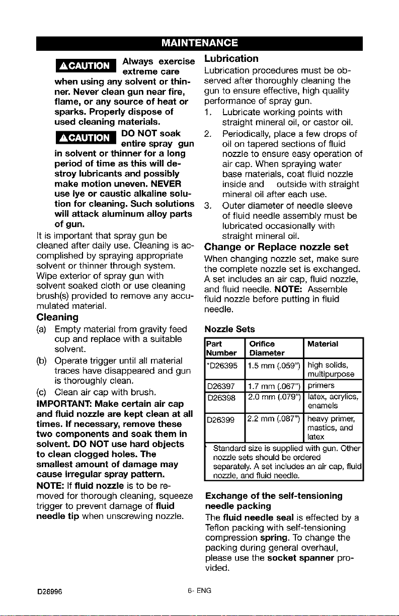
Change or Replace nozzle set
When changing nozzle set, make sure
the complete nozzle set is exchanged.
A set includes an air cap, fluid nozzle,
and fluid needle. NOTE: Assemble
fluid nozzle before putting in fluid
needle.
Nozzle Sets
Part Orifice Material
Number Diameter
*D26395 15 mm (059") high solids,
multipurpose
D26397 1.7 mm (.067") primers
D26398 2.0 mm (.079") latex, acrylics,
enamels
D26399 2.2 mm (.087") heavy primer,
mastics, and
latex
Standard size is supplied with gun. Other
nozzle sets should be ordered
separately. A set includes an air cap, fluic
nozzle, and fluid needle.
Exchange of the self-tensioning
needle packing
The fluid needle seal is effeeted by a
Teflon packing with self-tensioning
compression spring. To change the
packing during general overhaul,
please use the socket spanner pro-
vided.
D28996 6* ENG

NOTICE: See parts list to identify parts referred to in these Troubleshooting steps.
A.
B.
Defective Pattern
C. Spitting, irregular
or fluttering spray
D. Split spray pattern
E.
E
Unatomized or
spattered spray
Inadequate air de-
livery
G. Excessive fog
Likely Cause
Dried material is clog-
ging side-port "A" and r_
causing side-port "B"
®
to blow spray towards
the clogged side
B
Dried material at fluid c
nozzle "C" restricts air /
flow (_
Loose air nozzle
Air pressure set too
high
Fluid nozzle cracked or worn
Leak at thread of fluid nozzle
Leak at fluid needle
Needle packing worn out
Insufficient fluid in cup
Vent hole in container cover
clogged
Air pressure too high
Material too heavy
insufficient air pressure
Fluid pressure too high
Dried material on tip of fluid noz-
zle or air jets of air cap
Air needle partially closed
Dried material in air jets or air cap
Obstruction in air line
Air pressure to high for viscosity
of fluid
Suggested Remedy
Soak side-ports in thinner to
clean clog. DO NOT poke
any opening with hard
objects.
Remove air nozzle. Wipe off
fluid tip using a cloth soaked
in thinner or by soft brush
Fasten nozzle securely
Reduce air pressure
Tighten or replace
Tighten fluid nozzle
Tighten compression nut
assembly or replace needle
packing
Replace packing
Fill cup with fluid
Clean Out
Turn pattern control knob
clockwise to decrease fan
width. Turn fluid needle
adjusting nut counterclock-
wise to increase fluid flow
Thin material or use larger
orifice fluid nozzle set
Increase pressure to within
limit
Reduce pressu_
Clean
Open control knob
Clean
Remove obstruction
Reduce air pressure and/or
open fluid control knob
H. Material leaking Loose cup or foreign substances Tighten and clean or replace
from fluid inlet of on/between cup thread and fluid it
cup. inlet
I. Material leaking Worn fluid needle Replace
from nozzle when Dried material in tip of nozzle Clean
trigger is released Loose packing nut Tighten needle packing nut
by turning counterclockwise
7÷ENG D28996
I"J_._:_i_ I_'_I
2 3
39
37
5 6 789 10
3O
15
33
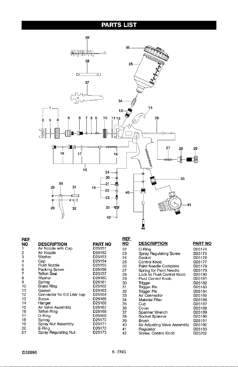
REF
_ PART NQ
1 Air Nozzle with Cap D25151
2 Air Nozzle D25152
3 Washer D25153
4 Cap D25154
5 Fluid Nozzle D25155
6 Packing Screw D25156
7 Teflon Sea_ D25157
8 Washer D25160
9 Spring D25161
10 Brass Ring D25162
11 Gasket D25163
12 Connector for 0.6 Liter cup D25164
13 Screw D25165
14 Hanger D25166
15 Air Valve Assembty D25167
16 Teflon Ring D25168
17 O-Ring D25169
18 Spring D25170
19 Spray Nut Assembly D25171
20 E-Ring D25172
21 Spray Regulating Nut D25173
REF
NO DESCRIPTION PART NO
22 O-Ring D25174
23 Spray Regulating Screw D25175
24 Gasket D25176
25 Control Knob D25177
26 Paint Needle Complete D25178
27 Spring for Paint Needle D25179
28 Lock to Fluid Control Knob D25180
29 Fluid Control Knob D25181
30 Trigger D25182
31 Trigger Pin D25183
32 Trigger Pin D25184
33 Air Connector D25185
34 Material Filter D25186
35 Cup D25187
36 Cover D25188
37 Spanner Wrench D25189
38 Socket Spanner D25190
39 Brush D25191
40 Air Adjusting VaJveAssembly D25192
41 Regulator D25193
42 Screw, Control Knob D25262
D28996 8* ENG
[_o]_hnl=1_11m[o]
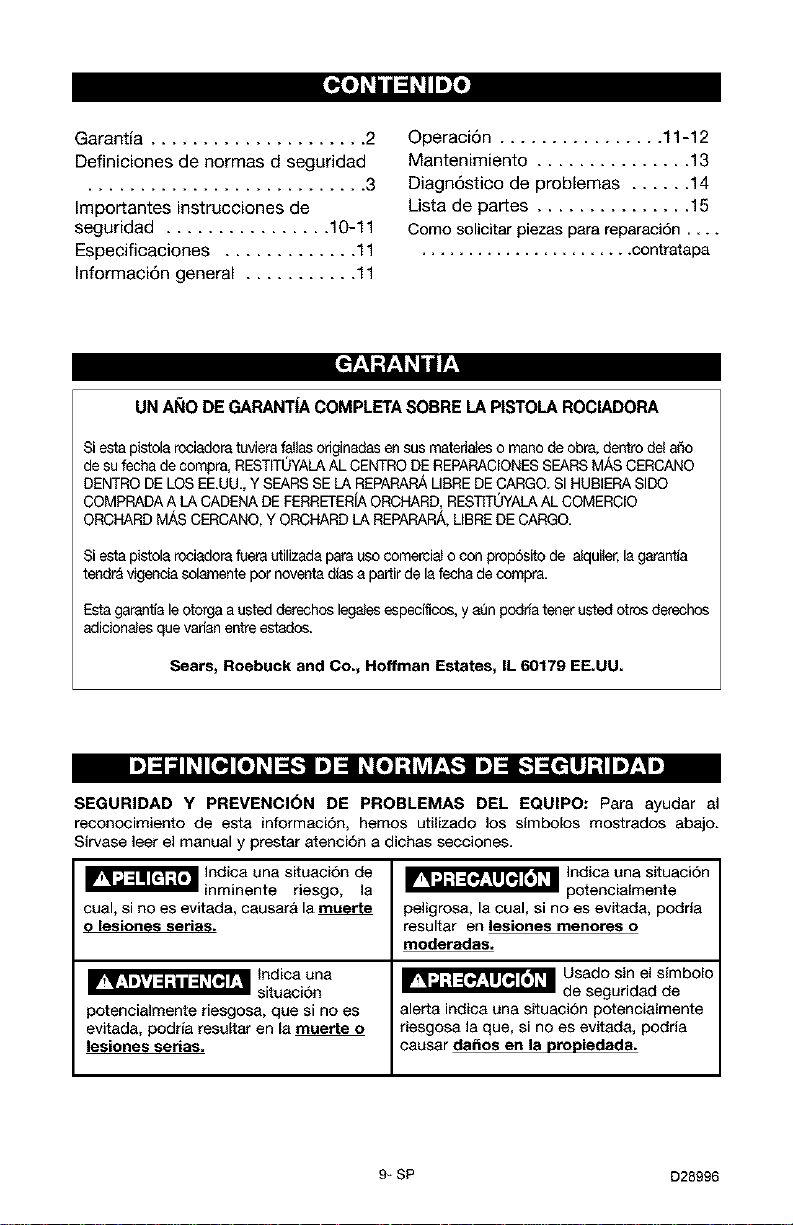
Garantia ..................... 2
Definiciones de normas d seguridad
........................... 3
Importantes instrucciones de
seguridad ................ 10-11
Especificaciones ............. 11
Informaci6n general ........... 11
Operaci6n ................ 11-12
Mantenimiento ............... 13
Diagn6stico de problemas ...... 14
Usta de partes ............... 15
Como solicitar piezas para reparaci6n ....
....................... contratapa
UNAI_IODEGARANTIACOMPLETASOBRELAPISTOLAROCIADORA
Siesta pistola rociadoratuviera fallas odginadasen sus matedaleso mano de obra,dentro de a_o
de su fecha de compra, RESTrrUYALAALCENTRO DEREPARAClONESSEARSM._SCERCANO
DENTRODELOS EE.UU. Y SEARS SE LA REPARARAMBREDECARGO.SI HUBIERASIDQ
COMPRADA A LACADENADEFERRETER[AORCHARD,RESTITOYALAALCOMERClO
ORCHARD M#,SCERCANO,Y ORCHARD LA REPARARA,UBRE DECARGO.
Si esla pistola rociadorafuera utilizadapara uso comercial o con propdsito de alquiler,la garant_a
tendr_ vigencia solarnentepot noventadias a partirde lafecha de compra.
Esta garantia leotorga austed derechos legalesespecificos, y a_n podria tenet usted otros derechos
adicionales quevadan entreestados.
Sears, Roebuck and Co., Hoffman Estates, IL 60179 EE.UU.
I,]=IalI_I[o'][o_]_J_-_I,]=IP_[_"] I']=L._dJJ ;11,7:1,]
SEGURIDAD Y PREVENCI(_N DE PROBLEMAS DEL EQUIPO: Para ayudar al
reconocimiento de esta informaci6n, hemos utilizado los simbolos mostrados abajo.
Sirvase leer el manual y prestar atenci6n a dichas secciones.
_'_'_'_ Indica una situacion de
inminente la
riesgo,
cual, si no es evitada, causar& la
o lesiones serias.
potencialmente riesgosa, que si no es
evitada, podria resultar en la muerte o
lesiones serias.
_ Indica una situaci6n
potencialmente
peligrosa, la cual, si no es evitada, podda
resultar en lesiones menores o
mederadas.
_ Usado sin el simbolo
de seguridad de
alerta indica una situacion potencialmente
riesgosa la que, si no es evitada, podria
causar da_os en la propiedada.
9-SP D28996
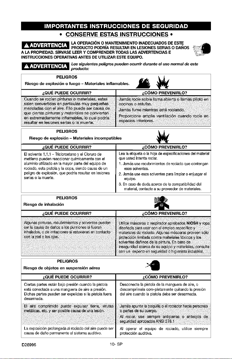
I1_v_I_o]-'tnf.,,t_hII=[-.__lJ_-,.'_l_llo,,_o,,][o_]_-."] ID1=_b"]_[e!l];,]I'7'-I,]
• CONSERVE ESTAS INSTRUCCIONES •
_LA OPERACION O MAN"rENIMIENTO INADEGUADOS DE ESTE
PRODUCTO PODRiA RESULTAR EN LESIONES SERIAS O DANOS
A LA PROPIEDAD. S|RVASE LEER Y COMPRENDER TODAS LAS ADVER_[ENCIAS E
INS'T_UCCIONES OPERATIVAS ANTES DE UTIUZAR ESTE EOUIPO.
_ LOSsiguientes peligros pueden ocurrir durante el uso normal de este
producto:
PELIGROS
Riesgo de explosi6n o fuego - Materiales inflamables.
&QUE PUEDE OCURRIR? &C(_MO PREVENIRLO?
PELIGROSRiesgo de explosibn - Materiales incompatibles
&QUE PUEDE OCURRIR? &C(_MO PREVENIRLO?
El solvente 1,1,1 - Tdelorcetanoy el Cloruro de Leala etiqueta o la hoja de especificaciones del material
metileno pueden reaccionarqulmicamente con el que usted intentarociar,
aluminio utiIizade en la mayor parte del equipo de t. Jam&s use recubrimientos de rociade que contengan
rociado, esta pistolay la cop& siendo causa de un esos solventes.
peligro de exploside, que podrla resu_aren lesiones 2. Jam&s use esossolventes para limp_aro enjuagar el
serias o ta muerte, equipo,
3. En caso de deda acerca de _acompatibiIided del
materiaJ,contacte a su proveedor de material.
PELIGROS _ ""
Riesgo de inhalaci6n
&QUE PUEDE OCURRIR? &C(_MO PREVENIRLO?
PELIGROS
Riesgo de objetos en suspensibn a_rea
&QUE PUEDE OCURRIR?
Ciertas partes est&n bajo preside cuando ]apistola
est&conectade a una manguera de aire a presi6n.
Dichas partes pueden ser expelidas si la pistola fuera
desarmade,
La exposicibn prolongada al rcciade del airepuede set
causa de dar_opermanente aJsistema auditivo,
&COMO PREVENIRLO?
Desconecte la pistola de la manguera de aire, o
descomprlmala com-pletamente quitande la presibn
del aire cuando la pistoladebaser desarmade.
AI operar et equipo de rociado, utilice siempre
protecci6n auditiva.
D28996 10-SP
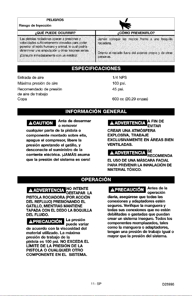
PEMGROS
Riesgo de Inyeccibn
i,QUE PUEDE OCURRIR? i,C(_MO PREVENIRLO?
Entrada de aire 1/4 NPS
M_txima presi6n de aire 100 psi
Recomendado de presi6n 45 psi.
de aire de trabajo
Copa 600 cc (20.29 onzas)
_Ante de desarmar
o remover
cualquier parte de la pistola o
componente montado sobre ella,
apague el compresor, libere la
presibn apretando el gatillo, y
desconecte el suministre de la
corriente el_ctrica, iJAMAS asuma
que la presibn del sistema es cerol
CREAR UNA ATMOSFERA
EXPLOSWA, TRABAJE
EXCLUSWAMENTE EN AREAS BIEN
VENTILADAS.
_SEcoMIENDA
EL USO DE UNA M/_SCARA FACIAL
PARA PREVENIR LA INHALACION DE
MATERIAL TOXICO.
PISTOLA ROCIADORA (POR ACCION
DEL REFLUJO) PRESIONANDO EL
GATILLO, MIENTRAS MANTIENE
TAPADA CON EL DEDO LA BOQUILLA
DEL FLUIDO.
_l.a presi6n
p_de variar
de acuerde con la viscosidad del
material utilizado. La maxima
presi6n de trabajo de la
pistola es 100 psi. NO EXCEDA EL
LiMITE DE LA PRESION DE LA
PISTOLA O CUALQUIER OTRO
COMPONENTE EN EL SISTEMA.
'a
diaria, asegdrese que todas las
conexiones y adaptadores est_n
seguros. Verifique la manguere y
todas sus conexiones que no estdn
debilitades o gastadas que puedan
crear un sistema inseguro. Todos los
componentes teemplazados, tales
como la manguera o adaptadores,
tengan una ptesibn de trabajo igual o
mayor que la presi6n del sistema.
11_ SP D28996
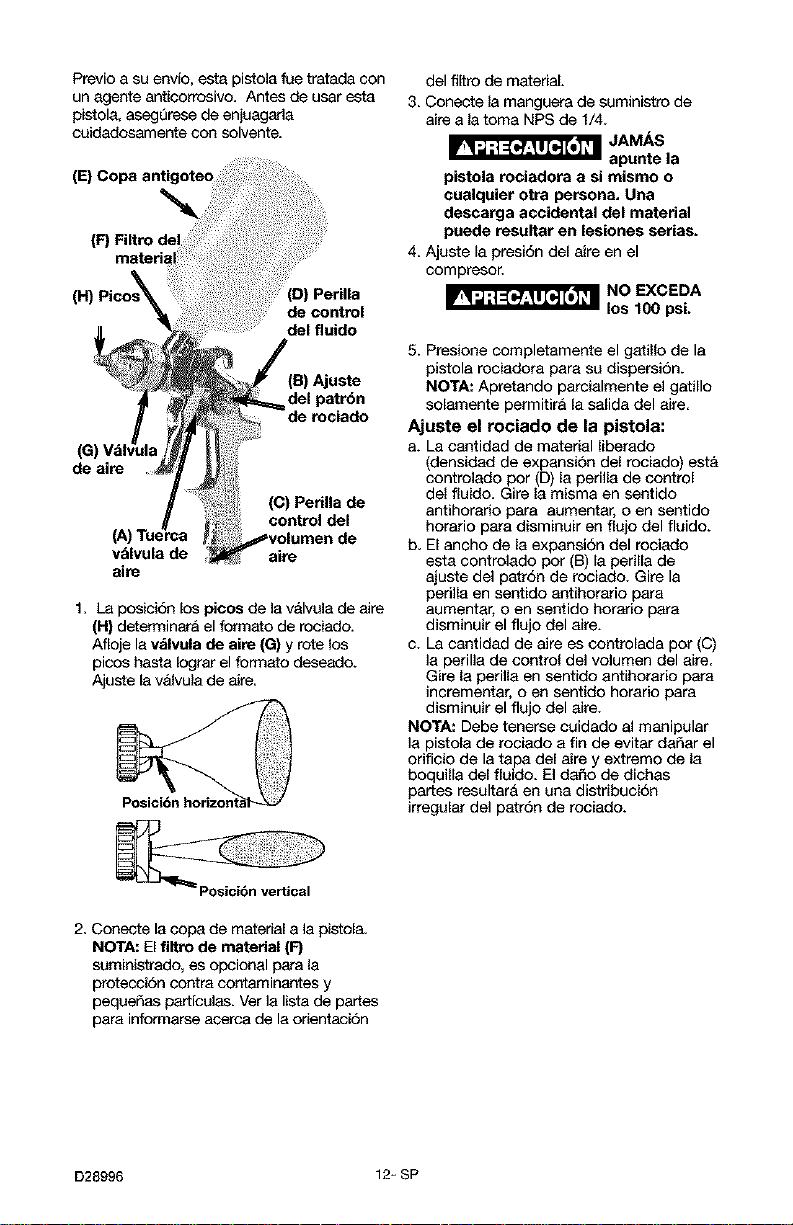
Previo a su envfo, esta pistola rue tratada con
un agente anticorrosivo. Antes de usar esta
pistola, asegerese de enjuagada
cuidadosamente con solvente.
Perilla
de control
del fluido
(B)Ajuste
de aire
(C) Perilla de
control del
valvula de aire
aire
1. La posici6n los picos de lavalvula de aire
(H) d_erminar& el formato de rociaclo.
Afloje la valvala de airs (G) y rote los
picos hasta bgrar el formato deseado.
Ajuste la vaJvulade aire.
del filtrode material.
3. Conecte la manguere de suministro de
aire a la toma NPS de 1/4.
_ JAMnAtS,a
pistola rociadora a si mismo o
cuelquier otra persona, Una
descarga accidental del materiel
puede resultar en leeionee serias.
4. Ajuste la presi6n del aire en el
compresor.
_NO EXCEDA
los 100 psi.
5. Presione completamente el gatillo de la
pistola rociadora para su dispersion.
NOTA: Apretando parcialmente el gatillo
solamente permitira la salida del aire.
Ajuste el rociado de la pistola:
a. La cantidad de material liberado
(densidad de expansi6n del rociado) esta
controlado por (D) la perilla de control
del fluido. Gire la misma en sentido
antihorario para aumentar, o en sentido
horario para disminuir en flujo del fluido.
b. El ancho de la expansi6n del roeiado
esta eontrolado por (B) la perilla de
ajuste del patr6n de rociado. Gire la
perilla en sentido antihorario para
aumentar, o en sentido horatio para
disminuir el flujo del aire.
c. La cantidad de aire es eontrolada por (C)
la perilla de control del volumen del aire.
Gire la perilla en sentido antihorario para
incrementar, o en sentido horario para
disminuir el flujo del aire.
NOTA: Debe tenerse cuidado el manipular
la pistola de rociado a fin de evitar daSar el
orifieio de la tapa del aire y extremo de la
boquilla del flaido. El da_o de dichas
pares resultara en una distribucidn
irregular del patr6n de rociado.
2. Conecte la copa de material a la pistol&
NOTA: Elfiltro de material (F}
saministrado, es opcional para la
protecoi6n contra contaminantes y
peqaeSas partfcules. Ver la lista de partes
para infon_qarseacerca de la orientaciSn
D28996 12_ SP
I_ViF.I_i i_ _IhVllll _i le]
_ Tenga siempre
extremo
cuidado al usar solventes o
diluyentes. Jambs limpie la pistola
eerca del fuego o llama abierta, o
caalquier otra fuente de calor o
chispas. Deseche adecaadamente los
materiales utilizados para la Iimpieza.
_NO O_je la
pistola a
remojo en solvente o dUuyente
pot un petiodo prolongado, dado
que este destruita lubricantes y
posiblemente tome desparejos los
movimientos. Jambs utilice lejfa o
productos causticos para la
limpieza, Tales soluciones atacarbn
las partes de la pistola con
aleaciones de aluminio.
Es importante que la pistola rociadora
quede limpia luego del uso diario. La
Iimpieza puede Iograrse enjuagando con
solvente o diluyenta adecuado a trav6s dal
sistama. Frote el exterior de la pistola
rociadora con an pa£_oembebido an
solvente o utilice el cepillo adjunto para
remover cualquier material acumulado.
Limpieza
(a) Limpie el material residual de la copa
alimentadora per gravedad y sustittTyalo
per un solvente adecuado.
(b) Mantenga el gatillo presionado hasta que
desaparezca todo rastro de material y la
pistola quede completamente limpia.
C) Limpie lav_llvulade airs con LInCelOillo.
IMPORTANTE: AsagQrese de que la v_tlvula
de aire y 18.boquilla del fluido sean
mantenidos limpios en todo momento. De
ser necesario, extraiga dichos componentas
y sam{_rjalos en solvente. NO UTILICE
objetos panzantes para Iimpiar orificios
obtarados. Un pequeSo daSo paede
ocasionar la irregularidad del formato de
rociado.
NOT/k."Si la boquilla del fluido va a ser
ramovida para aria Iimpieza completa,
mantanga el gatiUo prasionado al
desenroscar la boqailla, para pravenir daSos
en la punta de la aguja del fluido.
Lubricacibn
Los siguientes procedimientos de
lubricacion deben observarsa cuando se
limpie completamente la pistola, para poder
asegurar su efectividad y alta calidad de
rendimiento de la pistola rociador&
1. Lubrique los puntos de trabajo con an
aceite mineral puro, o aceite castor.
2. PeriSdicamante coloque unas gotas de
aeeite en las secciones ehaflanadas de
las boqaillas a fin de asegarar la
operaci6n Iibre de la v_tlvula de aire. AI
rociar materiales de base acuosa,
cubra las partas interior y exterior de la
boquilla del fluido con aceite mineral
puro luego de cada uso.
3. La parte externa del di_etro del buje
de 18.agaja del flaido, debeser
lubricada ocasionalmente con aceite
mineral puro.
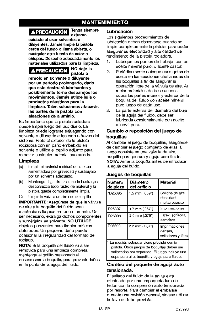
Cambio o reposicibn del juego de
boquillas
AI cambiar el juego de boquillas, asegQrese
de cambiar el juego completo de elias. El
juego consista en ana v&lvula de aire,
boquilla para pintura y aguja para fluido.
NOTA: Arme la boquilla antes de introducir
la aguja dal fluido.
Juegos de boquillas
Ndmero Dibmetro Material
de pieza del orificio
*D26395 1.5 mm (,059") S61idos de alta
densiclad,
multiprop6sito
D26397 1.7 rnrn (.067") Irnprirnaciones
D26398 2.0 mm (.079") LA4ex,acrflicos,
esmaltes
D26399 2.2 mm (.08T') Imprimaciones
densas,
selladores y l_ite>
La medida est_indar viene provist8 con Ia
pistol& Otros juegos de boquillas deben set
solicitados por separaclo. El juego incluye una
copa para aire, boquilla y aguja para fluido.
Cambio del paquete de aguja auto
tensionada.
El sellado del fluido de la aguja est61
efectuado por una empaquetadura de
tefl6n con la compresion auto tensionada
por resorte. Para cambiar el embalaje
durante una ravisi6n general, sfrvase utilizar
la Ilave de tubo provista+
13_ SP D28996
I.] r:Te'_'-]UL[_e] .] _ ".htTe]:]! _ _vff:T.']
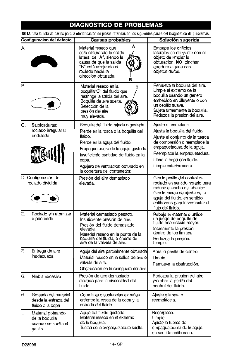
NOTA:Yea$aIistadepaflesparalaidentificaci6ndepSezasrefefidasenlossiguientespasoscIelDiagn6sficodeproNemas.
Oonfiguraci6n del defecto Cauaaa probables Soluci6n augetida
A Matedat reseco que A Empape los odficios
est&obtarando la salida J laterales en di3uyentecon el
lateral de "A". siendo la objeto de limpiar la
causa de que la salida obturaci6n, NO pinchar
"B" est_ arrojando el abertura alguna con
rociado hacia la objetos duros,
direcci6n obturad&
B
B. Material reseco enla C Remuevala boquilla det8ire.
boqailia"C" del fluido qae / Limpieel extremo de la
restHngela salida del aire, / boquilla asando an genera
Boquil_ade aJresuelt& _ embebido endiluyente o con
Selecci6n de la ('_ _ uncepillo suave,
presi6n del aire _ Sujetefin_qementela boquill&
muy elevada. Reduzcala presi6n del aire.
C. Salpicaduras;
rociado irregular u
ondulado
Boquilla de[fluido rajadao gastada.
Pierde en la rosca o la boquilla del
flaido.
Pierde en laegaja de fluido.
Empaquetadura de la aguja gastada.
Insuflciente cantidad de fluido en la
cop&
Agujero de ventilaci6n obturado en
la cobertupade_contenedo_
Ajuste o reemp_ace.
Ajuste _aboquilla del flaido.
Ajuste el conjunto de lataerca
de compresi6n o reemp_acela
empaqaetadara de la egaja.
Reemplace la empaquetadura.
Llenela copa con flaido.
Limpieextefion_qente.
D. Configaraci6n de Presi6n del aire demasiado Gire la perilladel control de
rociado dividida elevada, rociado en sentido horatio paPa
reducir el ancho del abanico.
Gire latuerca de ajuste de la
eguja del fluido, ensentido
antihorado para incrementarel
fluio de_fluido.
E. Rociado sin atomizar Material demasiado pesado. Rebaje el material o utilice
o punteado Insaficiente presi6n de aire. un juego de bogui_tade
Presi6ndel fluido demasiado fluido con orificio mayor.
elevada. Incremente la presi(_n
dentro de los limites.
Material reseco en la puntade la
boquilla de_fluido o chorro de Reduzca la presi6n.
a re de a va vu a de are. Limpie.
E Entrega de aire Agujadel aire parcialmente obturada Abra la perilla de control.
inadecuada Matedal reseco en_asalida de aireo Umpie.
valvulade air& Remueva la obstrucci6n.
Obstrucci6n en la manguerade aire.
G. Niebla excesiva Presi6n de aire demasiado Redazcala presi6n del aire
elevada para la viscosidad del y/o abra la peril_adel
fluido, control del fluido,
H. Goteado del matedal Copa floja o sustancias extraSas Ajaste y limpie o
desde la entrada del en/entre la rosca de la copa y la reempl_cela.
fluido o la copa entrada del fluido.
I. Matedal goteando Aguja del fluido gastada. Reemplace.
de la boquilla Materialreseco en el extremo Limpie.
cuando se suelta el de la boquilla. Ajuste la tuercade
gatillo. Tuercade la empaquetadupasueffa, empeguetadura de la aguja
en sentido antihopado.
D28996 14- SP
2 3
37
5 6 789
14
/
26
17 18
15
33
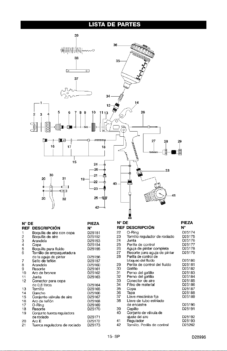
N° DE PIEZA N° DE PIEZA
REF DESCRIPCI(_N N° REF DESCRIPCI(_N N°
1 Boquitta de aire con copa D25151 22 O=Ring D25174
2 Boquilta de aire D25152 23 Tornillo regulacior de rociado D25175
3 Arandela D25153 24 Junta D25176
4 Copa D25154 25 Peritta de control D25177
5 Boquilta para fluido D25155 26 Aguja de pintar complet a D25178
6 Tot nillode empaquetadura 27 Resorte pa_a aguja de pintar D25179
de ia aguja de pintar D25156 28 Perilla de controt de
7 Sello de tefI6n D25157 btoqueo del fluido D25180
8 Arandela D25160 29 Peritta de control del ftuido D25181
9 Resor[e D25161 30 Gatillo D25182
10 Aro de bronce D25162 31 Perno del gatilto D25183
11 Junta D25163 32 Perno del gatitto D25184
12 Conector ga_a copa 33 Conector de aire D25185
de 0,6 titros D25164 34 Filtro de matedal D25186
13 Tornillo D25165 35 Copa D25187
14 Gancho D25166 36 Tapa D25188
15 Conjunto v&Ivula de ake D25167 37 Uave mecAnica fija D25189
16 Aro de teft6n D25168 38 Uave de tubo estriado
17 O-Ring D25169 de encastre D25190
18 Resor[e D25170 39 Cepilto D25191
19 Coniunto tuerca reguladora 40 Conjunto de v&lvula de
de rocia_o D25171 aiuste delaire D25192
20 Aro E D25172 41 Regulador D25193
21 Tuerca reguladora de rociado D25173 42 Tornillo. Perilla de control D25262
15-SP D28996

Get itfixed, at your home or ours!
Your Home
For repa=r- in your home - of all major brand apphances,
lawn and garden equipment, or heating and cooling systems,
no matter who made it, no matter who sold it!
For the replacement parts, accessories and
owner's manuals that you need to do-it-yourself
For Sears professional installation of home appliances
and items like garage door openers and water heaters
1-800-4-MY-HOME_ Anytime day or n_ght
(1-800 469 4663) (U S A and Canada)
www.sears.com www seers c_
OurHome
For repair of carry-in products like vacuums, lawn equipment,
and electronics, call or go on-hne for the nearest
Sears Parts and Repair Center.
1-800-488-1222 Anytime, dayor n_ght (U SA only)
www sears com
To purchase a protection agreement on a productserviced by Sears
1-800-827-6655 (u s A) 1-800-361-6665 (Canal)
Para pedlrsewlclo de reparaclSn
a demlcdlo, y para ordenar plezas
1.888-SU-HOGAR _
(1438_784_427)
Au Canada pour ser_ce en frar_als
1-800-LE-FOYER uc
_14]005336837t
www sears ca
, E/A/RS
© Se_s Roeb_ and Co
r_
,_#ReglsteredTradernark "tTradernark _ Se_ce Mark of Sears, RoebuCk ahd Co
,_#Marca Reg_st[ada ;t Marca de Fabrtca "rl Marc3 de Serwcpo de Sears Roebuck and Co
Hb
r*c Marque de commerce Marque deposee de Sears, Roebuck and Co