Loading ...
Loading ...
Loading ...
Installation
102
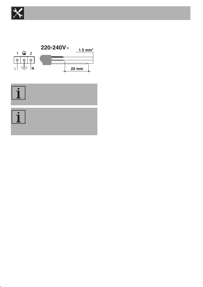
The appliance can work in the following
modes:
• 220-240 V 1N~
3 x 1.5 mm² three-core cable.
Fixed connection
Fit the power line with an all-pole
disconnection switch, with a clearance
between its contacts that allows the
complete disconnection as per the
overvoltage category III, in compliance
with the installation regulations.
Connection with plug and socket
Make sure that the plug and socket are of
the same type.
Avoid using adapters, gang sockets or
extensions as these could cause
overheating and a risk of burns.
5.5 Instructions for the installer
• The plug must be accessible after
installation. Do not bend or trap the
power cable.
• The appliance must be installed
according to the installation diagrams.
• Do not try to unscrew or force the
threaded elbow of the fitting. You may
damage this part of the appliance,
which may void the manufacturer’s
warranty.
• Use soap and water to check for gas
leaks on all connections. DO NOT use
naked flames when looking for leaks.
• Turn on all the burners separately and at
then all together to make sure that the
gas valve, burner and ignition are
working properly.
• Turn the burner knobs to the minimum
position and check that the flame is
stable for each individual burner and all
the burners together.
• If the appliance does not work correctly
after having carried out all the checks,
contact your local Authorised Service
Centre.
• Once the appliance has been installed,
please explain to the user how to use it
correctly.
The values indicated above refer
to the cross-section of the internal
lead.
The aforementioned power cables
are sized taking into account the
coincidence factor (in compliance
with standard EN 60335-2-6).