O
+
_ @u curer.fro Page 2 Thursday, July 3, 20113 1:47 PM
OWNER'S MANUAL
_ @00 RX-VI400U EN.book Page 2
Thursday, July 10, 2003 12:17 AM
+
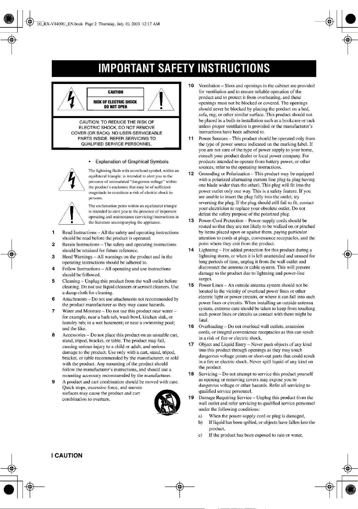
CAUTION
RISKOFELECTRICSHOCK
DONOTOPEN
CAUTION: TO REDUCE THE RISK OF
ELECTRIC SHOCK, DO NOT REMOVE
COVER (OR BACK). NO USER-SERVICEABLE
PARTS INSIDE. REFER SERVICING TO
QUALIFIED SERVICE PERSONNEL.
• Explanation of Graphical Symbols
The lightning flash with arrowhead symboh within an
equilateral triangle, is intended to alert you to tile
presence of tminsulaled "dangel ous voltage" within
the product's encJosme that may be of sufl]cien_
magnitude to constitute a ri,k of electric shock to
The exclamation Ix_int within an equilateral triangle
is intended to alert you to file presence of inq_r taut
ot_erating and maintenance (servicing) instructions in
tile literature accompanying the appliance.
1 Read Instructions - All the safety and operating instructions
should be read before the product is operated.
2 Retain Instructions - The safety and operating instructions
should be retained fk)r future reference.
3 Heed Warnings -- All warnings on the product and in the
operating instructions should be adhered m.
4 Follow fnstructions -- All operating and use instructions
should be fMlowed.
fi Cleaning - Unplug this product fl'om the wall outlet before
cleaning. Do not use liquid cleaners or aerosol cleaners. Use
a damp cloth fk)r cleaning.
6 Attachments -- Do not use attachments not recommended by
the product nmnufacturer as they may cause hazards.
7 Water and Moisture ---Do not _se this product near water --
for example, near a bath tub, wash bowl, kitchen sink, or
laundry tub; in a wet basement; or near a swimming pool;
and the like.
8 Accessories -- Do not place this product on an unstable cart,
stand, trip)d, bracket, or table. The product may fall,
causing serious injury to a child or adult, and serious
damage to the product. Use only with a cart, stand, tripod,
bmckeh or table recommended by the manufacturer, or sold
with the product. Any mounting of the product should
follow the manuf)cturer's instructions, and should use a
mounting accessory recommended by the manuf)cturer.
9 A product and cart combination should be moved with care.
Quick stops, excessive fbrce, and uneven
surfaces may cause the product and cart
combination to overturn.
10 Ventilation - Slots and openings in the cabinet are provided
for ventilation and to ensure reliable operation of the
product and to protect it fi'om overheating, and these
openings must not be blocked or covered. The openings
should never be blocked by placing the product on a bed,
sofa, rug, or other similar surfSce. This product should not
be placed in a built-in installation such as a bookcase or rack
unless proper ventilation is provided or the manufacturer's
instructions have been adhered to.
1"1 Power Sources This product should be operated only fron]
the type of power source indicated on the marking label. If
you are not sure of the type of power supply to your home,
consult your product dealer or local power company. For
products intended to operate fi'om battery power, or other
sources, reler to the operating instructions.
12 Grounding or Polarization -- This product may be equipped
with a polarized alternating current line plug (a plug having
one blade wider than the other), This plug will fit into the
power outlet only one way. This is a safety leatare. If you
are unable to insert the plug fblly into the outlet, try
reversing the plug. If the plug should still fail to fit, contact
your electrician to replace your obsolete outlet. Do not
deleat the safety purpose of the polarized plug.
13 Power-Cord Protection -- Power-supply cords should be
routed so that they are not likely to be walked on or pinched
by items placed upon or against them, paying particular
attention to cords at plugs, convenience receptacles, and the
point where they exit from the pr(_uct.
14 Lightning -- For added protection f_r this product during a
lightning storm, or when it is left unattended and unused fk)r
long periods of time, unplug it from the wall outlet and
disconnect the antenna or cable system. This will prevent
damage m the product due to lightning and powe_line
surges.
1fit Power Lines - An outside antenna system should not be
located in the vicinity of overhead power lines or other
electric light or power circuits, or where it can fall into such
power lines or circuits. When installing an outside antenna
system, extreme care should be taken to keep fi'om touching
such power lines or cimuits as contact with them might be
fatal
1 fit Overloading -- Do not overload wall outlets, extension
cords, or integral convenience receptacles as this can result
in a risk of tim or electric shock.
17 Object and Liquid Entry .- Never push objects of any kind
into this product through openings as they may touch
dangerous voltage points or short-out parts that could result
in a fire or electric shock. Never spill liquid of any kind on
the product.
18 Servicing - Do not attempt to service this product yourself
as opening or removing covers may expose you to
dangerous voltage or other hazm'ds. Refer al! servicing to
qualified service personnel.
19 Damage Requiring Service --- Unplug this product from the
wall outlet and ref}r servicing to qualified service personnel
under the following conditions:
a) When the power-supply cord or plug is damaged,
b) If liquid has been spilled, or objects have fallen into the
product,
c) If the product has been exposed to rain or water,
+
I CAUTION
_ @0(LRX-VI400U EN.book Page 3
Thursday, July 10, 2003 12:17 AM
d) If the product does not operate normally by following 24
the ope_ ating instructions. Adjust only those controls
that are covered by the operating instructions as an
improper adjustment of other controls may result in
damage and will often require extensive work by a
qualified technician to restore the product to its normal
operation,
e) If the product has been dropped or damaged in any
way, and
f) When the product exhibits a distinct change in perfk_r-
mance - this indicates a need fi,)r service.
20 Replacement Parts When replacement parts are required,
be sure the service technician has used replacement parts
specified by the manufacturer or have the same
characteristics as the original part. Unauthorized
substitutions may result in fire, electric shock, or other
hazards.
2"1 Safety Check - Upon completion of any service or repairs to
this product, ask the service technician to perform safety
checks to determine that the product is in proper operating
condition.
22 Wall or Ceiling Mounting - The unit should be mounted
to a wall or ceiling only as recommended by the
manufacturer.
2:3 Heat The product should be situated away from heat
sources such as radiators, heat registers, stoves, or other
products (including amplifiers) that produce heat.
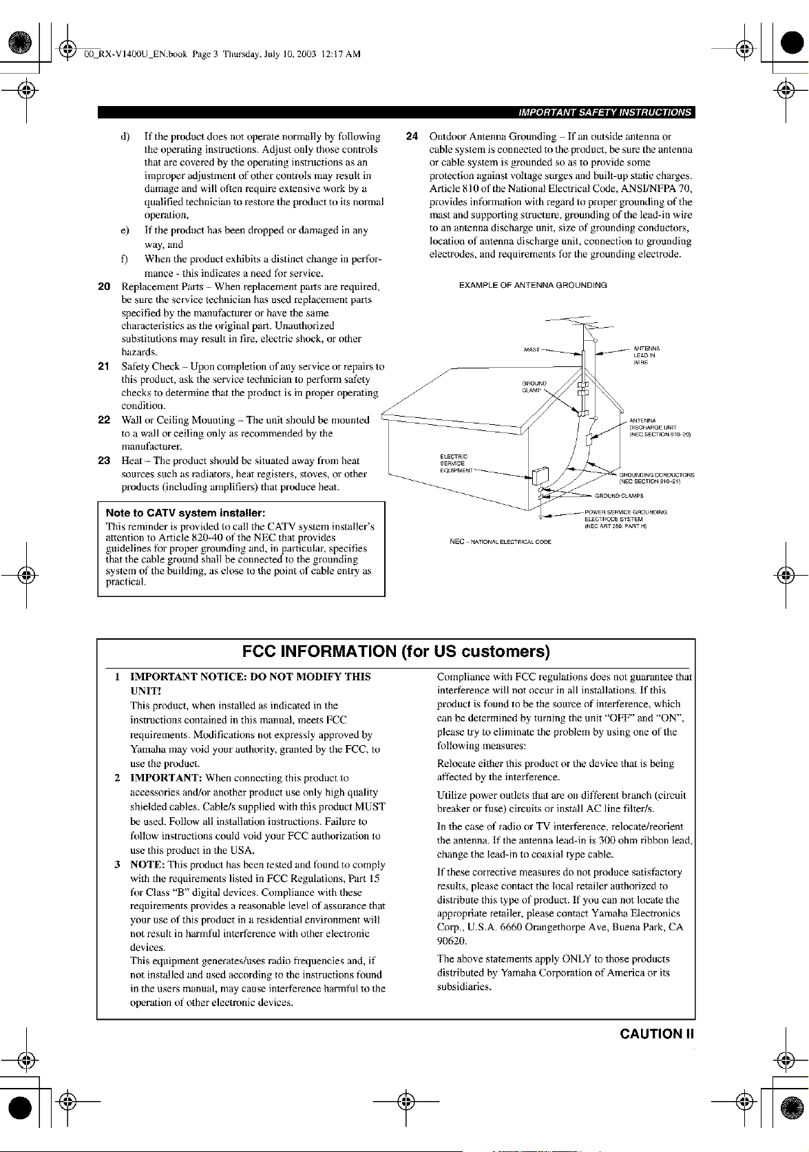
Outdoor Antenna Grounding - If an outside antenna or
cable system is connected to the product, be sure the antenna
or cable system is grounded so as to provide some
protection against voltage surges and built-up static charges.
Article 810 of the National Electrical Code, ANSI/NFPA 70,
provides infk_rmation with regard to proper grounding of the
mast and supporting structure, grounding of the lead-in wire
m an antenna discharge unit, size of grounding conductors,
location of antenna discharge unit, connection to grounding
electro,des, and requirements fpe the grounding electrode.
EXAMPLE OF ANTENNA GROUNDING
+
Note to CATV system installer:
This reminder is provided to call the CATV system installer's
attention to Article 820-40 of the NEC thai provides
guidelines fbr proper grounding and, in particular, specifies
that the cable ground shall be connected to the grounding
system of the building, as close to the point of cable entry as
practical.
NEC_NA_ONALELECTRICALCODE
+
FCC INFORMATION (for US customers)
1 IMPORTANT NOTICE: DO NOT MODIFY THIS
UNIT!
This pr(_uct, when installed as indicated in the
instructions contained in this manual, meets FCC
requirements. Modifications not expressly approved by
Yamaha may void your authority, granted by the FCC, to
use the product.
2 IMPORTANT: When connecting this product to
accessories and/or another pr(_uct use only high quality
shielded cables. Cable/s supplied with this product MUST
be used. Follow al! installation instructions. Failure to
l\)llow instructions could void your FCC authorization to
use this product in the USA.
3 NOTE: This product has been tested and found to comply
with the requirements listed in FCC Regulations, Part 15
l\)r Class "B" digital devices. Compliance with these
requirements provides a reasonable level of assurance that
your use of this product in a residential environment will
not result in harmfi_l inlerterence with other electronic
devices.
This equipment generates/uses radio frequencies and, if
not installed and used according to the instructions found
in the users manual, may cause in{erfkrence harmful to the
operation of other electronic devices.
Compliance with FCC regulations does not guarantee that
interference will not occur in all installations. If this
product is foued to be the source of interterence, which
can be determined by turning the unit "OFF' and "ON",
please try to eliminate the problem by using one of the
fbllowing measures:
Relocate either this product or the device that is being
al_ected by the interterence.
Utilize power outlets that are on dift}rent branch (circuit
breaker or fi_se) circuits or install AC line filter/s.
In the case of radio or TV interf}rence, relocate/reorient
the anlenna. If the antenna lead-in is 300 ohm ribbon lead
change the lead-in to coaxial type cable.
If these corrective measures do not produce sa{isfactory
results, please contact the local retailer authorized to
distribute this type of product. If you can not locate the
appropriate retailer, please contact Yamaha Electronics
Corp., U.S.A. 6660 Orangethorpe Ave, Buena Park, CA
90620.
The above statements apply ONLY to those products
distributed by Yamaha Corporation of America or its
subsidiaries.
CAUTION
_ _00N RX-V 14L_IUEN.book Page4
Thursday, July 10, 2003 12:17 AM
+
1 TO assure the finest performance, please read this
manual carefully. Keep it in a safe place for future
reference.
2 Install this sound system in a well ventilated, cool,
dry, clean place -- away from direct sunlight, heat
sources, vibration, dust, moisture, and/or cold.
Allow ventilation space of at least 30 cm on the top,
20 cm on the left and right, and 20 cm on the back of
this unit.
3 Locate this unit away from other electrical
appliances, motors, or transformers to avoid
humming sounds.
4 Do not expose this unit to sudden temperature
changes from cold to hot, and do not locate this unit
in a environment with high humidity (i.e. a room with
a humidifier) to prevent condensation inside this
unit, which may cause an electrical shock, fire,
damage to this unit, and/or personal injury.
5 Avoid installing this unit where foreign object may
fall onto this unit and/or this unit may be exposed to
liquid dripping or splashing. On the top of this unit,
do not place:
- Other components, as they may cause damage
and/or discoloration on the surface of this unit.
- Burning objects (Le. candles), as they may cause
fire, damage to this unit, and/or personal injury.
- Containers with liquid in them, as they may fall
and liquid may cause electrical shock to the user
and/or damage to this unit.
6 Do not cover this unit with a newspaper, tablecloth,
curtain, etc. in order not to obstruct heat radiation. If
the temperature inside this unit rises, it may cause
fire, damage to this unit, and/or personal injury.
7 Do not plug in this unit to a wall outlet until all
connections are complete.
8 Do not operate this unit upside-down. It may
overheat, possibly causing damage.
9 Do not use force on switches, knobs and/or cords.
10 When disconnecting the power cord from the wall
outlet, grasp the plug; do not pull the cord.
11 Do not clean this unit with chemical solvents; this
might damage the finish. Use a clean, dry cloth.
12 Only voltage specified on this unit must be used.
Using this unit with a higher voltage than specified
is dangerous and may cause fire, damage to this
unit, and/or personal injury. YAMAHA will not be
held responsible for any damage resulting from use
of this unit with a voltage other than specified.
13 To prevent damage by lightning, disconnect the
power cord from the wall outlet during an electrical
storm.
14 Do not attempt to modify or fix this unit. Contact
qualified YAMAHA service personnel when any
service is needed. The cabinet should never be
opened for any reasons.
15 When not planning to use this unit for long periods
of time (i.e. vacation), disconnect the AC power plug
from the wall outlet.
16 Be sure to read the"TROUBLESHOOTING" section
on common operating errors before concluding that
this unit is faulty.
17 Before moving this unit, press STANDBY/ON to set
this unit in the standby mode, and disconnect the
AC power plug from the wall outlet.
18 VOLTAGE SELECTOR (Asia and General models
only)
The VOLTAGE SELECTOR on the rear panel of this
unit must be set for your local main voltage BEFORE
plugging into the AC main supply.
Voltages are 110/12012201230-240 V AC, 50160 Hz.
WARNING
TO REDUCE THE RISK OF FIRE OR ELECTRIC
SHOCK, DO NOT EXPOSE THIS UNIT TO RAIN
OR MOISTURE.
This unit is not disconnected fi'om the AC power source as
long as it is connected to the wall outlet, even if this unit itself
is turned off. This state is called the standby mode. In this
state, this unit is designed m consume a very small quantity of
power:
FOR CANADIAN CUSTOMERS
"Ib prevent electric shock, match wide blade of plug to
wide slot and fully insert.
This Class B digital apparatus complies with Canadian
ICES-O03.
IMPORTANT
Please record the serial number of this unit in the space
below.
MODEL:
Serial No.:
The serial number is localed on the rear of the unit.
Retain this Owner's Manual in a safe place for future
reference.
We Want You Listening For A Lifetime
YAMAHA and the Electronic Industries Association's Consumer
Electronics Group want you to get the most out of your
equipment by playing it at a safe level. One that lets the sound
come through loud and clear without annoying blaring or
distoltion - and, most impol tantly, without afi_cting your
sensitive bearing.
Since hearing damage fi'om loud sounds is often
undetectable until it is too late, YAMAHA and the
Electronic Industries Association's Consumer
Electronics Group recommend you to avoid
prolonged exposure fi'om excessive volume levels. ,.=,=_us'r_ttx_
III CAUTION
+
_ L_@00 RX-VI400U EN.book Pagel
?
Thursday, July 10, 2003 12:17 AM
+
FEATURES ............................................................. 2
GETTING STARTED ............................................ 3
Supplied accessories .................................................. 3
Installing batteries in the remote control ................... 3
CONTROLS AND FUNCTIONS ......................... 4
Front panel ................................................................. 4
Remote control ........................................................... 6
Using the remote control ........................................... 7
Front panel display .................................................... 8
Rear panel ................................................................ 10
SPEAKER SETUP ............................................... 11
Speaker placement ................................................... 11
Speaker connections ................................................ 12
CONNECTIONS .................................................. 15
Betore connecting components ................................ 15
Connecting video components ................................. 16
Connecting audio components ................................. 19
Connecting the antennas .......................................... 21
Connecting the power supply cord .......................... 22
Speaker impedance setting ...................................... 23
Turning on the power ............................................... 23
AUTO SETUP ....................................................... 24
Introduction .............................................................. 24
Optimizer microphone setup .................................... 24
Starting the setup ..................................................... 25
BASIC SETUP ...................................................... 28
Using BASIC setup .................................................. 28
PLAYBACK .......................................................... 30
Basic operations ....................................................... 30
Selecting sound field programs ............................... 32
Selecting input modes .............................................. 34
TUNING ................................................................ 36
Automatic and manual tuning .................................. 36
Presetting stations .................................................... 37
Selecting preset stations ........................................... 39
Exchanging preset stations ...................................... 39
RECORDING ........................................................ 40
SOUND FIELD PROGRAM
DESCRIPTIONS ............................................... 41
For movie/video sources .......................................... 41
For music sources .................................................... 43
if!!i
ADVANCED OPERATIONS .............................. 44
Selecting the OSD mode .......................................... 44
Using the sleep timer. .............................................. 44
Manually adjusting speaker levels ........................... 45
Using the test tone ................................................... 46
SET MENU ............................................................ 47
Using SET MENU ................................................... 48
Manual setup: SOUND ............................................ 49
Manual setup: INPUT .............................................. 54
Manual setup: OPTION ........................................... 56
REMOTE CONTROL FEATURES ................... 59
Control area ............................................................. 59
Setting manufacturer codes ...................................... 60
Programming codes from other remote controls ,.,.. 61
Changing source names in the display window....... 62
Clearing l_nction sets .............................................. 63
Clearing individual tunctions .................................. 63
Controlling each component .................................... 64
ZONE 2/ZONE 3
(U.S.A., Canada and Australia
models only) ....................................................... 68
Zone 2/Zone 3 connections ...................................... 68
Remote controlling Zone 2/Zone 3.......................... 69
EDITING SOUND FIELD PARAMETERS ......71
What is a sound field ............................................... 71
Changing parameter settings ................................... 71
SOUND FIELD PARAMETER
DESCRIPTIONS ............................................... 73
TROUBLESHOOTING ....................................... 77
GLOSSARY ........................................................... 82
SPECIFICATIONS ............................................... 85
_ @0(! RX-VI40(IU EN.book Page 2
Thursday, July 10, 2003 12:17 AM
Built-in 7-channel power amplifier
• Minimum RMS Output Power
(0,04% THD, 20 Hz - 20 kHz, 8ff2)
Front: II0W+I10W
Center: 110 W
Sun'ound: II0W+ II0W
Sun'ound Back: 110 W + 110 W
Sound field features
• Proprietary Yamaha technology for the creation of
sound fields
• THX
• Dolby Digital/Dolby Digital EX Decoder
• DTS/DTS ES Matrix 6.1, Discrete 6.1, DTS
Neo:6 Decoder, DTS 96/24
• Dolby Pro Logic/Dolby Pro Logic II Decoder
• Virtual CINEMA DSP
• SILENT CINEMA _
Sophisticated AM/FM tuner
• 40-Station Random Access Preset Tuning
• Automatic Preset Tuning
• Preset Station Shifting Capability (Preset Editing)
Other features
• YPAO: Yamaha Parametric Room Acoustic Optimizer
for Aulomalic Speaker Setup
• 192-kHz/24-bitD/AConverler
• "SET MENU" which Provides You with Ilems for
Optimizing This Unit for Your Audio/Video System
• 6 or 8-channel External Decoder Input for Other Future
Formals
• On Screen Display Function Helpful in Controlling
This Unit
• S Video Signal Input/Output Capability
• Component Video lnput/Oulput Capability
• Video Signal Conve_sion (Composite Video <-+
S Video --->Component Video) Capability for Monilor
Out
• Optical and Coaxial Digital Audio Signal Jacks
• Sleep Timer
• Night Listening Mode
• Remote Control wilh Preset Manufacturer Codes
• Zone 2/Zone 3 Custom lnstallalion Facility (U.S.A.,
Canada and Australia models only)
• g_': indicates a tip for your operalion.
• Some operalions can be performed by using either the buttons on the main unit or on the remote control. In cases when the bat_on
names difl?r between the main unit and the remote control, the button name on the remote control is given in parentheses.
• This manual is printed prior to production. Design and specifications are subject m change in part as a result of improvements, etc. In
case of dil}}rences between the manual and product, the pr{_uct has priority.
Ilrlra- -I
DIQITAL" EX
r_J-_.llrNmm_
Mannfactm-ed under license fi'om Dolby Laboratories.
"Dolby", "Pro Logic", and the double-D symbol are trademarks
of Dolby Laboratories.
SILENT CINEMA is a trademark of YAMAHA
CORPORATION.
"DTS" and "DTS-ES Digital Surround" and "Neo:6" are
trademarks of Digital Theater Systems, Inc.
THX SURROUND EX
THX and tile THX logo are registered trademarks of THX Ltd.
Surround EX is a jointly developed technology of THX and
Dolby Laboratories, Inc. and is a trademark of Dolby
Laboratories, Inc. All rights reserved. Used under authorization.
2
_ @0(t RX-VI40I)U EN.book Page 3
Thursday, July 10, 2003 12:17 AM
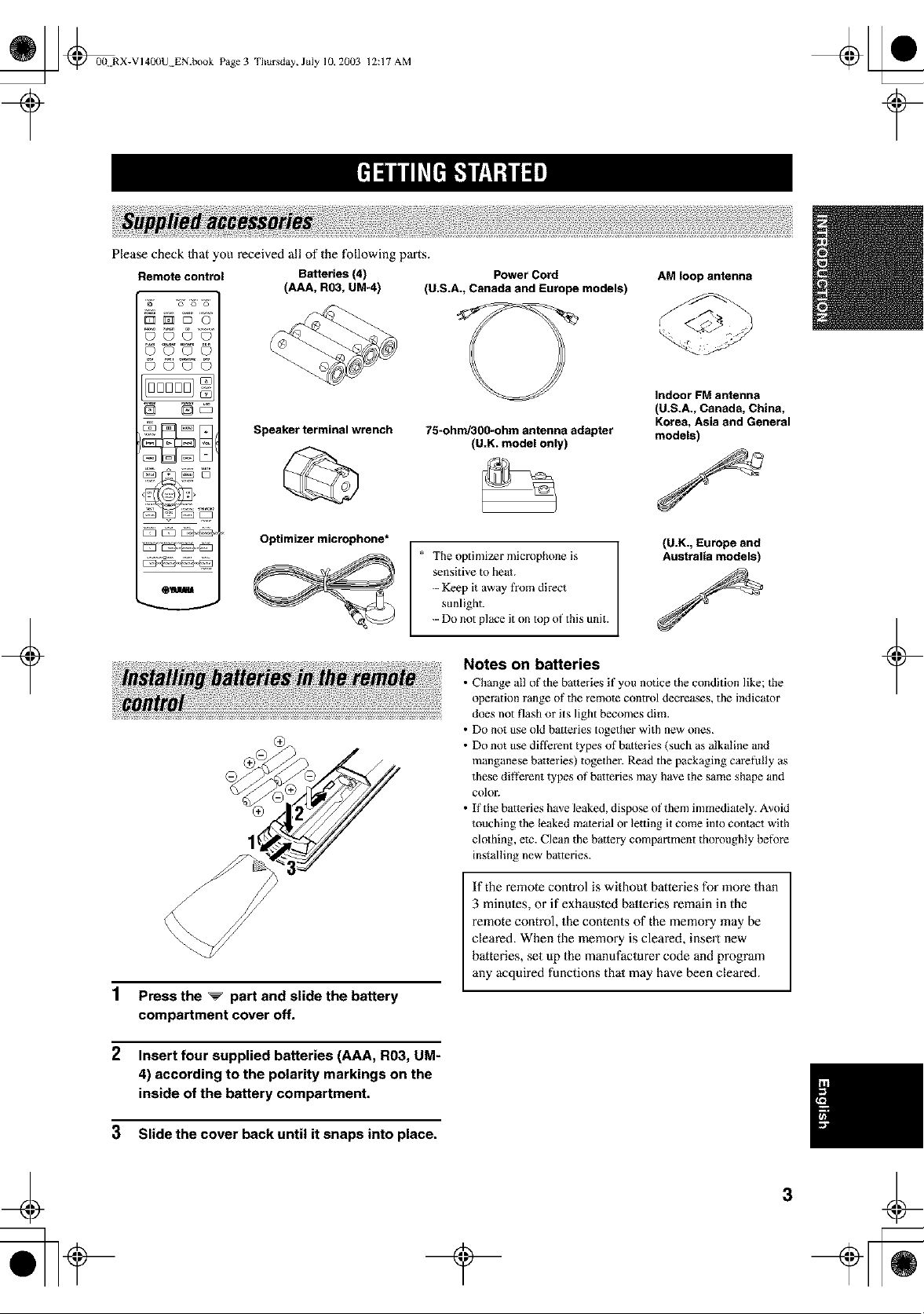
Please check 1hat you received all of the following parts.
Remote control Batteries (4)
(AAA, R03, UM-4)
+
©©©0
© ©'_©
N No5
[ZZ3[553__ _
OI
Speaker terminal wrench
Optimizer microphone*
Power Cord
(U.S.A., Canada and Europe models)
75-ohnd300-ohm antenna adapter
(U.K. model only)
* The optimizer microphone is
sensitive to heat.
-- Keep it away from direct
sunlight.
-- Do not place it on top of this unit.
AM loop antenna
Indoor FM antenna
(U.S.A., Canada, China,
Korea, Asia and General
models)
(U.K., Europe and
Australia models)
1 Press the _ part and slide the battery
compartment cover off.
2 Insert four supplied batteries (AAA, R03, UM-
4) according to the polarity markings on the
inside of the battery compartment.
3 Slide the cover back until it snaps into place.
Notes on batteries
• Change all of the batteries if you notice the condition like; the
operation range of the remote control decreases, the indicator
does not flash or its light becomes dim.
• Do not use old batteries together with new ones.
• Do not use diflerent types of batteries (such as alkaline and
manganese batteries) together. Read the packaging carefully as
these di}_rent types of batteries may have the same shape and
coloL
• If the batteries have leaked, dispose of them immediately. Avoid
touching the leaked material or letting it come into contact with
clothing, elc. Clean the battery compartment thoroughly before
installing new batteries.
If the remote control is without batteries for more than
3 minules, or if exhausled balleries remain in the
remote control, the contents of the memory may be
cleared. When the memory is cleared, insert new
batteries, set up the manufaclurer code and program
any acquired functions thai may have been cleared.
+
¢
_ _00 RX-VI40(IU EN.book Page4
Thursday, July 10, 2003 12:17 AM
+
_YAIIAHA
/
o,1.
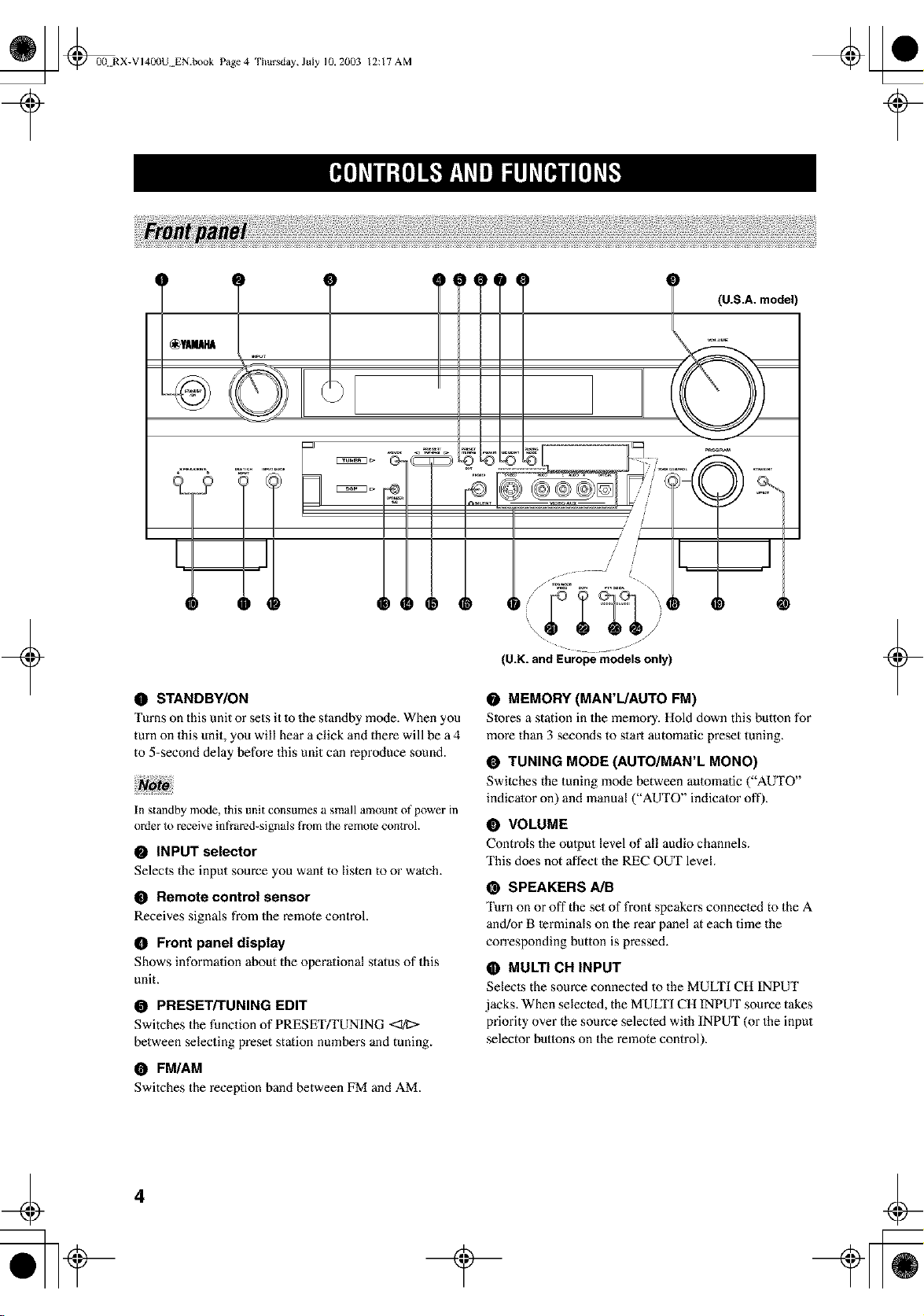
(U.K. and Europe models only)
O STANDBY/ON
Turns on this unit or sets it 1o the standby mode. When you
turn on this unit, you will hear a click and there will be a 4
to 5-second delay before this unit can reproduce sound.
In standby mode, this unit consumes a small amount of power in
order to receive infrared-signals from the remote controh
• INPUT selector
Selects the input source you want to listen to or watch.
• Remote control sensor
Receives signals from the remote controh
O Front panel display
Shows information about the operational status of this
unit.
PRESET/TUNING EDIT
Switches the function of PRESET/TUNING <:I/I>
between selecting preset station numbers and tuning.
O FM/AM
Switches the reception band between FM and AM.
0 MEMORY (MAN'L/AUTO FM)
SIores a station in the memory. Hold down this button for
more than 3 seconds to start automalie preset tuning.
• TUNING MODE (AUTO/MAN'L MONO)
Switches the tuning mode between aulomalic ("AUTO"
indicator on) and manual ("AUTO" indicalor oft').
O VOLUME
Controls the output level of all audio channels.
This does not affect the REC OUT level.
@ SPEAKERS A/B
Turn on or off the set of front speaker,s connected to the A
and/or B terminals on the rear panel at each time the
corresponding button is pressed.
O MULTI CH INPUT
Selecls the source connected to the MULTI CH INPUT
jacks. When selected, the MULTI CH INPUT source takes
priority over the source selected with INPUT (or the input
selector butlons on the remote control).
+
4
_ @00N RX-VI40(IU EN.book Page 5
IIJI_T|I:[OII_."Ir__y_T/II[II, lhlII_I[O]_I
+
Thursday, July 10, 2003 12:17 AM
O INPUT MODE
Sets the priority (AUTO, DTS, ANALOG) for the type of
signals received when one component is connected to two
or more of this unit's input jacks (see page 34). Priority
cannol be set when MULTI CH INPUT is selecled as 1he
input source.
@ OPTIMIZER MIC jack
Use to connect and input audio signals from the supplied
microphone for use with the AUTO SETUP function (see
page 24).
0 AIBICID/E
Selects one of the 5 preset station groups (A Io E).
O PRESET/TUNING
Selects preset stalion number 1 to 8 when the colon (:) is
displayed next to the band indication in the front panel
display,
Selects the tuning frequency when the colon (:) is not
displayed.
(_, SILENT (PHONES jack)
Outputs audio signals for private lislening with
headphones. When you connect headphones, no signals
are output to the OUTPUT jacks or Io the speakei:s.
All Dolby Digital and DTS audio signals are mixed down
to the left and right headphone channels.
• VIDEO AUX jacks
Input audio and video signals from a portable external
source such as a game console. "Ib reproduce source
signals from these jacks, select V-AUX as the input
source.
• U.K. and Europe models only
RDS MODF-JFREQ
Press this button when the unit is receiving an RDS stafion
to cycle the display mode between the PS mode, I:vI'Y
mode, RT mode, CT mode (if the station offers those RDS
data service) and/or the fi'equency display mode.
EON
Press this button to select a radio program type (NEWS,
INFO, AFFAIRS, SPORT) to tune in automatically.
@ PTY SEEK MODE
Press this button to set the unit Io the IYI'Y SEEK mode.
O PTY SEEK START
Press this butlon to begin searching for a station after the
desired program type has been selecled in the l:Vl'Y SEEK
mode.
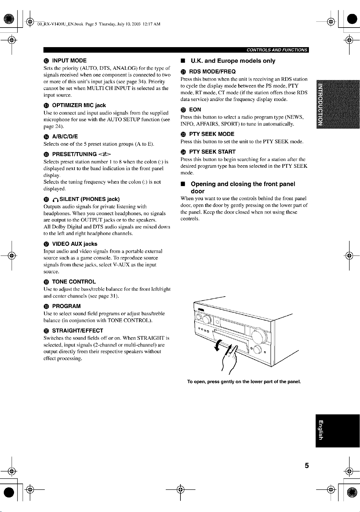
• Opening and closing the front panel
door
When you want to use the controls behind the front panel
door, open the door by gently pressing on the lower part of
the panel. Keep the door closed when not using these
controls.
TONE CONTROL
Use to adjust the bass/treble balance for the front left/right
and center channels (see page 31).
@ PROGRAM
Use to select sound field programs or adjust bass/treble
balance (in conjunction with TONE CONTROL).
@ STRAIGHT/EFFECT
Switches the sound fields off or on. When STRAIGHT is
selected, input signals (2-channel or multi-channel) are
output directly from their respective speakex_s without
effect processing.
+
To open, press gently on the lower part of the panel.
_ @0(t RX-VI40(IU EN.book Page 6
Thursday, July 10, 2003 12:17 AM
+
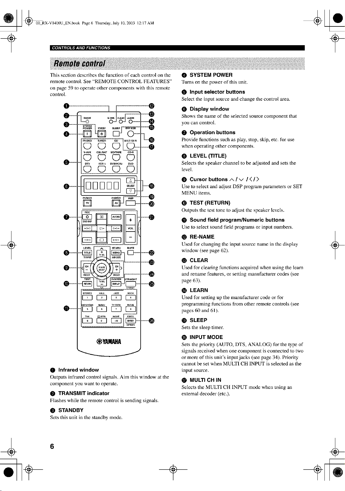
This section describes the function of each control on the
remote control. See "REMOTE CONTROL FEATURES"
on page 59 to operate other components with this remote
control.
O
........(DCD
v./glx C_T MDn'A_ CD_
(DCD
vc_ _ _/g/vcR2
(D (D (D (D
DDDDD
D
N
gEc
m
VOL
)--TU _ -
s,_Eo ROt;K
_ [553 r=7 Z
@YAHAHA
®
O Infrared window
Outputs infrared control signals. Aim this window at the
component you want Io operate.
O TRANSMIT indicator
Flashes while the remote control is sending signals.
STANDBY
Sets this unit in the standby mode.
O SYSTEM POWER
Turns on the power of this unit.
O Input selector buttons
Select the input source and change the control area.
O Display window
Shows the name of the selected source component that
you can control.
O Operation buttons
Provide functions such as play, slop, skip, elc. for use
when operating other components.
• LEVEL (TITLE)
Selects the speaker channel to be adjusled and sets the
level.
O Cursor buttons zx / v / ( / ;'
Use to select and adjust DSP program parameters or SET
MENU items.
@ TEST (RETURN)
Outputs the test 1one to adjust the speaker levels.
O Sound field program/Numeric buttons
Use Io select sound field programs or input numbe_.
RE-NAME
Used for changing the input source name in the display
window (see page 62).
CLEAR
Used for clearing functions acquired when using the learn
and rename features, or setting manufacturer codes (see
page 63).
LEARN
Used for setting up the manufacturer code or for
programming functions from other remote controls (see
pages 60 and 61 ).
@ SLEEP
Sets Ihe sleep timer.
INPUT MODE
Sets the priority (AUTO, DTS, ANALOG) for the type of
signals received when one component is connected to two
or more of this unit's input jacks (see page 34), Priority
cannot be set when MUffI'I CH INPUT is selecled as the
input source.
MULTI CH IN
Selects the MULTI CH INPUT mode when using an
external decoder (etc.).
+
6
_ @0(t RX-VI400U EN.book Page 7
Thursday, July 10, 2003 12:17 AM
IIJI_T|I,_{OIIK"Ir'_tI_T/IIIIIhlIIIIII[O]_ll
@ SELECT L_/V
Selects another component thai you can control
independently of the input component selected with the
input seleclor butlons.
@ AV POWER
Turns on and oft" the power of the component selected by
the input selector butlon.
@ AMP
Selects AMP or other component selected by the input
seleclor button.
@ VOL -/+
Increases or decreases the volume level.
O MUTE
Mules the sound. The MUTE indicator turns on when the
MUTE function is on. Press again to restore the audio
output to the previous volume level.
@ SET MENU (MENU)
Selects the SET MENU mode.
• ON SCREEN (DISPLAY)
Selects the on-screen display (OSD) mode for your video
monitor.
O STRAIGHT/EFFECT
Swilches the sound fields off" or on. When STRAIGHT is
selected, input signals (2-channel or multi-channel) are
output directly from their respective speakex:s without
effect processing.
@ EX/ES
Turns the Dolby Digital EX or DTS ES decoder on or off.
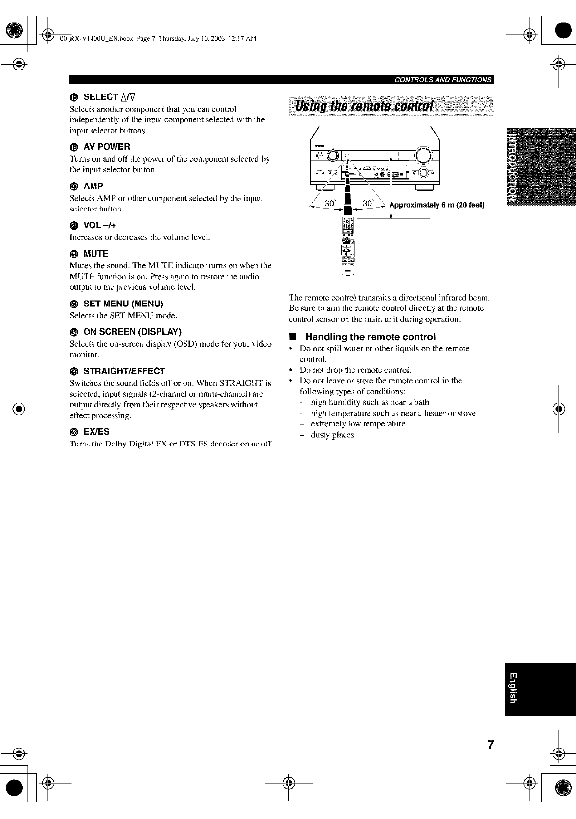
The remote control transmits a directional infrared beam.
Be sure to aim the remote control directly at 1he remote
control sensor on the main unit during operation.
• Handling the remote control
• Do not spill water or other liquids on the remote
control.
• Do not drop lhe remote control.
• Do not leave or store the remote control in the
following types of conditions:
- high humidily such as near a bath
- high lemperature such as near a hearer or slove
- extremelylow temperature
- dusty places
_ @00N RX-VI40(IU EN.book Page 8
Thursday, July 10, 2003 12:17 AM
(U.S.A., Canada and
Australia models only)
(U.K. and Europe models only)
+
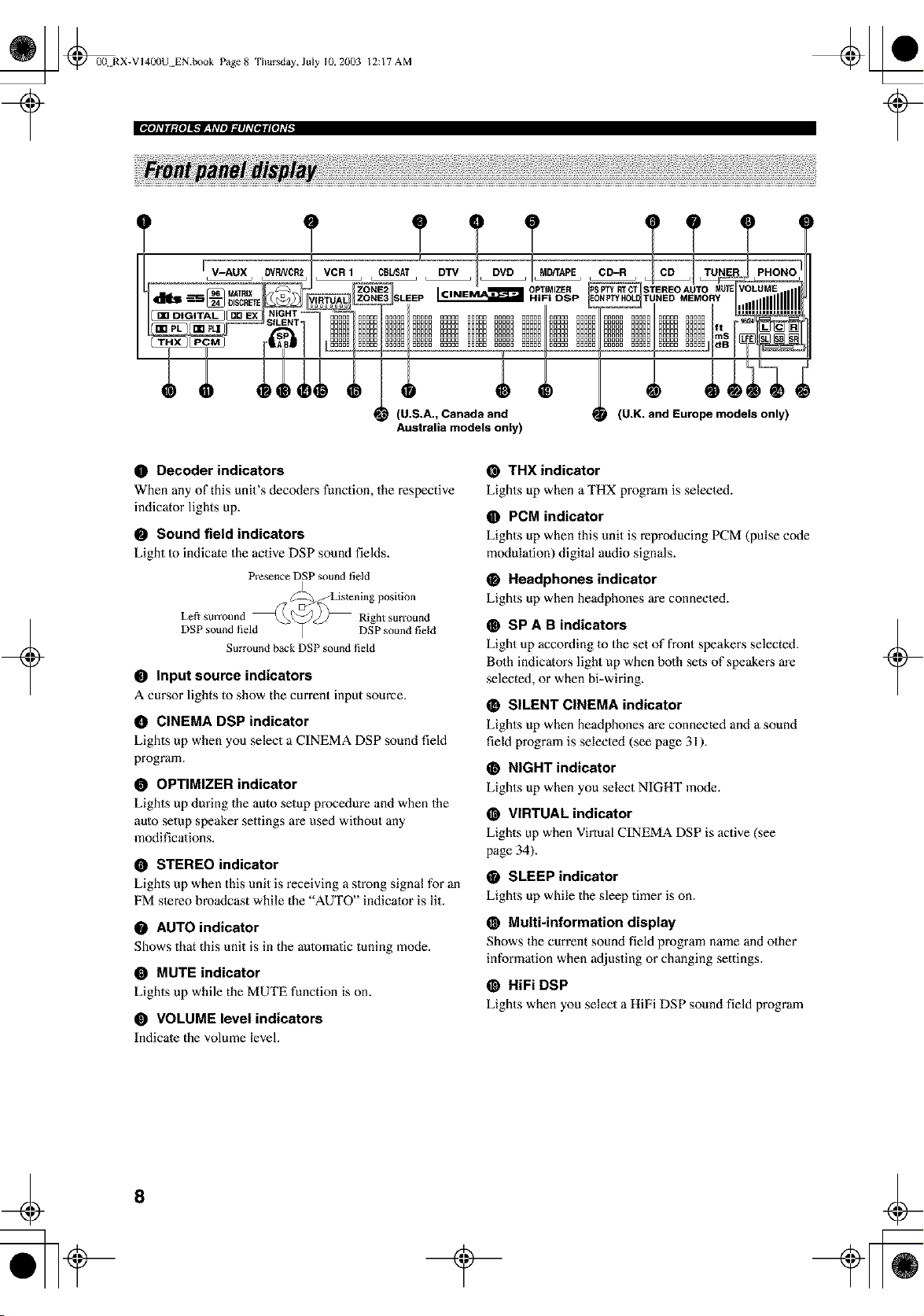
O Decoder indicators
When any of this unit's decoders function, the respective
indicator lights up.
• Sound field indicators
Light to indicate the active DSP sound fields.
Presence DSP sound field
DSP sound field
Right surround
DSP sound field
Surround back DSP sound field
• input source indicators
A cursor lights to show the current input source.
O CINEMA DSP indicator
Lights up when you select a CINEMA DSP sound field
program.
O OPTIMIZER indicator
Lights up during the auto setup procedure and when the
aulo setup speaker settings are used without any
modifications.
O STEREO indicator
Lights up when this unit is receiving a strong signal for an
FM stereo broadcast while the AUTO indicato'is lit.
O AUTO indicator
Shows that this unit is in the aulomatic tuning mode.
• MUTE indicator
Lights up while the MUTE function is on.
• VOLUME level indicators
Indicate the volume level.
@ THX indicator
Lights up when a THX program is selected.
• PCM indicator
Lights up when this unit is reproducing PCM (pulse code
modulation) digital audio signals.
O Headphones indicator
Lights up when headphones are connected.
O SP A B indicators
Light up according 1o the set of front speakers selected.
Bolh indicators light up when both sets of speakers m'e
selected, or when bi-wiring.
O SILENT CINEMA indicator
Lights up when headphones are connected and a sound
field program is selected (see page 31).
O NIGHT indicator
Lights up when you select NIGHT mode.
O VIRTUAL indicator
Lights up when Virtual CINEMA DSP is active (see
page 34).
• SLEEP indicator
Lights up while the sleep timer is on.
@ Multi-information display
Shows the current sound field program name and other
information when a_ljusting or changing settings.
@ HiFi DSP
Lights when you select a HiFi DSP sound field program
+
8
_ @0(t RX-V 140()U EN.book Page9
Thursday, July 10, 2003 12:17 AM
ffJI_T|Ig{OIIK'f'_tI_T/II.']Ih_III_II[O]_II
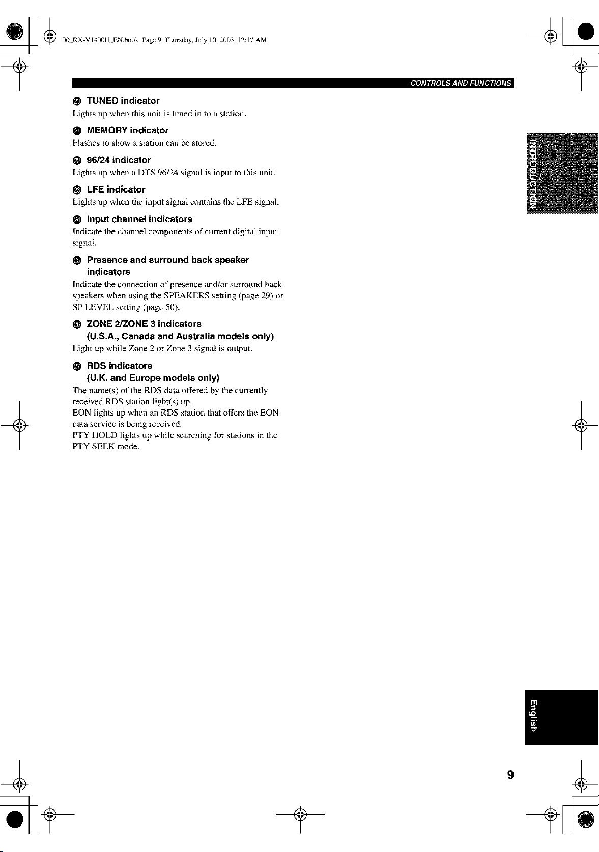
@ TUNED indicator
Lights up when this unit is tuned in to a station.
@ MEMORY indicator
Flashes to show a station can be stored.
O 96/24 indicator
Lights up when a DTS 96/24 signal is input Io this unit.
@ LFE indicator
Lights up when the input signal contains the LFE signal.
O Input channel indicators
Indicate the channel components of current digital input
signal.
• Presence and surround back speaker
indicators
Indicate the connection of presence and/or surround back
speakei_s when using the SPEAKERS setting (page 29) or
SP LEVEL setting (page 50).
O ZONE 2/ZONE 3 indicators
(U.S.A., Canada and Australia models only)
Light up while Zone 2 or Zone 3 signal is oulput.
+
RDS indicators
(U.K. and Europe models only)
The name(s) of the RDS data offered by the cun'ently
received RDS stalion light(s) up.
EON lights up when an RDS station that offers 1he EON
data service is being received.
PTY HOLD lights up while searching for stations in the
IrI'Y SEEK mode.
+
_ @0(t RX-VI400U EN.book Page 10 Thursday, July 10, 20(13
12:17 AM
'_=@@
t@@
=@@
-@@
I I@°'-_®
I
@@-@ @ i'@@@
@@_@@ @@@
@@,:@@=°="-:-:---
@@-@@ =_]
= E@@•
_"-® ____=.@Q.
"@@ i_@
@@@@ i _"
m
®
+
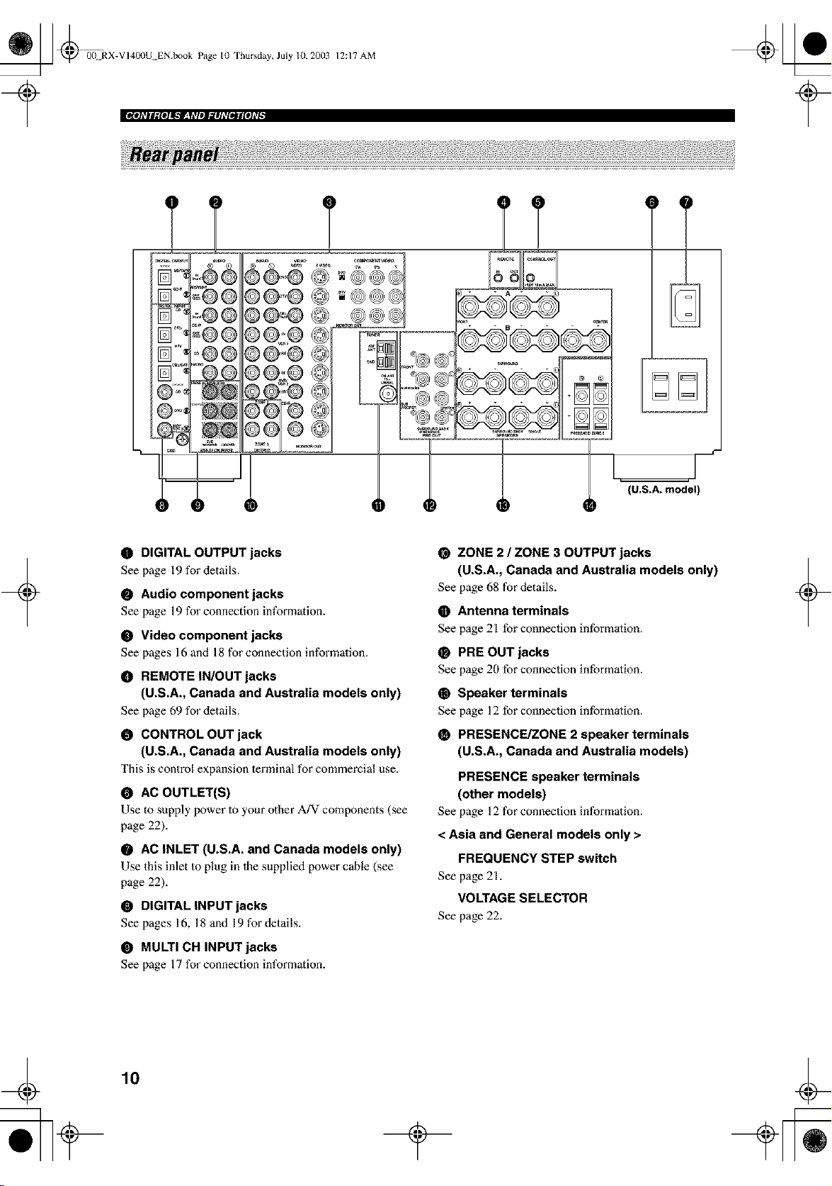
O DIGITAL OUTPUT jacks
See page 19 for details.
@ Audio component jacks
See page 19 for connection information.
@ Video component jacks
See pages 16 and 18 for connection information.
O REMOTE IN/OUT jacks
(U.S.A., Canada and Australia models only)
See page 69 for details.
O CONTROL OUT jack
(U.S.A., Canada and Australia models only)
This is control expansion lerminal for commercial use.
AC OUTLET(S)
Use to supply power Io your other A/V components (see
page 22).
O AC INLET (U.S.A. and Canada models only)
Use this inlet Io plug in Ihe supplied power cable (see
page 22).
O DIGITAL INPUT jacks
See pages 16, 18 and 19 for details.
• MULTI CH INPUT jacks
See page 17 for connection information.
ZONE 2 / ZONE 3 OUTPUT jacks
(U.S.A., Canada and Australia models only)
See page 68 for details.
• Antenna terminals
See page 21 for connection intbrmation.
O PRE OUT jacks
See page 20 for connection intbrmation.
O Speaker terminals
See page 12 for connection intbrmation.
PRESENCE/ZONE 2 speaker terminals
(U.S.A., Canada and Australia models)
PRESENCE speaker terminals
(other models)
See page 12 for connection information.
< Asia and General models only >
FREQUENCY STEP switch
See page 21.
VOLTAGE SELECTOR
See page 22.
+
¢
10
_ @00 RX-VI400U EN.book Page II
?
Thursday, July 10,2003 12:17 AM
+
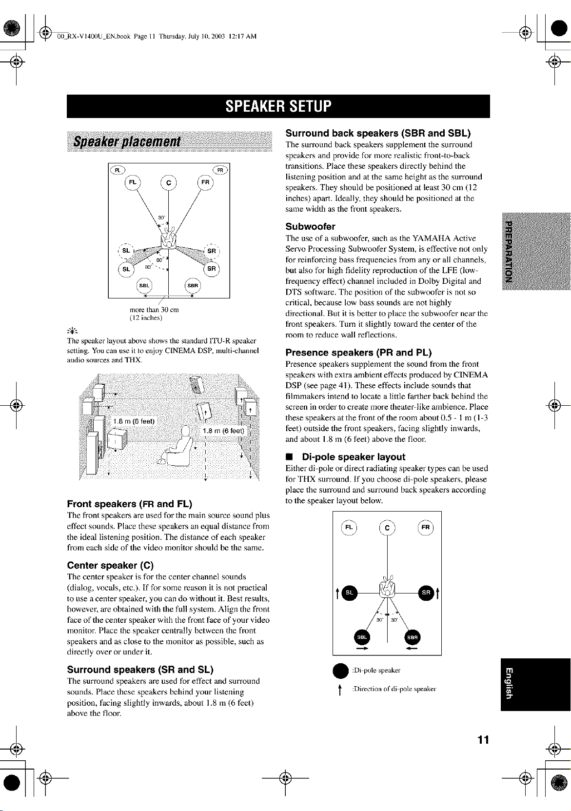
/
more than 30 cm
( 12 inches)
.,+,.
The speaker layout above shows the standard ITU-R speaker
setting. You can use it to enjoy CINEMA DSP, multi-channel
audio sources and THX.
Front speakers (FR and FL)
The front speakers are used for the main source sound plus
effect sounds. Place these speakers an equal distance from
the ideal listening position. The distance of each speaker
fi'om each side of the video monilor should be the same.
Center speaker (C)
The center speaker is for the center channel sounds
(dialog, vocals, etc.). If for some reason it is nol practical
to use a center speaker, you can do without it. Best results,
however, are obtained with the full syslem. Align the front
face of the center speaker with the front face of your video
monitor. Place lhe speaker centrally between the front
speakers and as close to the monilor as possible, such as
directly over or under it.
Surround speakers (SR and SL)
The surround speakers are used for effect and surround
sounds. Place these speakers behind your lislening
position, facing slightly inwards, about 1.8 m (6 feet)
above the floor.
Surround back speakers (SBR and SBL)
The surround back speakers supplement the surround
speakers and provide for more realistic front-to-back
transitions. Place these speakers directly behind the
listening position and at the same height as the surround
speakers. They should be positioned at least 30 cm (12
inches) aparl. Ideally, they should be positioned al the
same width as the front speakers.
Subwoofer
The use of a subwoofer, such as the YAMAHA Active
Servo Processing Subwoofer Syslem, is effective not only
for reinforcing bass frequencies from any or all channels,
but also for high fidelity reproduction of the LFE (Iow-
fi'equency effect) channel included in Dolby Digital and
DTS software. The position of the subwoofer is no1 so
critical, because low bass sounds are nol highly
directional. But it is better to place the subwoofer near lhe
front speakers. Turn it slightly toward the center of the
room to reduce wall reflections.
Presence speakers (PR and PL)
Presence speakers supplement the sound from the front
speakers with extra ambient effects produced by CINEMA
DSP (see page 41). These effects include sounds thai
filmmakers intend 1o locate a little farther back behind the
screen in order 1o create more theater-like ambience. Place
these speakers at the front of the morn about 0.5 - 1 m ( 1-3
feet) outside the front speakers, facing slightly inwards,
and about 1.8 in (6 feet) above the floor.
• Di-pole speaker layout
Either di-pole or direct radiating speaker types can be used
for THX surround. If you choose di-pole speakers, please
place the sun'ound and surround back speakers according
to the speaker layout below.
! :Di-pole speaker
:Direclion of di=pole speaker
11
+
_ @0(t RX-VI400U EN.book Page 12 Thursday, July lU, 20(13
12:17 AM
Be sure to connect the left channel (L), right channel (R),
"+" (red) and "-" (black) properly. If the connections are
faulty, no sound will be heard from the speakers, and if the
polarity of the speaker connections is incorrect, the sound
will be unnalural and lack bass.
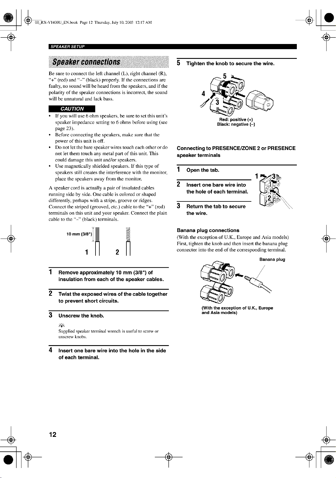
5 Tighten the knob to secure the wire.
4
I[_JIJi!aJ/l
• If you will use 6 ohm speaker,s, be sure to set this unit's
speaker impedance setting to 6 ohms before using (see
page 23).
• Before connecting the speakers, make sure that the
power of this unit is off.
• Do no1 let the bare speaker wires touch each other or do
not let them touch any metal pm't of this unit. This
could damage this unit and/or speakers.
• Use magnetically shielded speakers. If this type of
speaker,s still creates the interference wilh the monitor,
place the speakers away from the monilor.
A speaker cord is actually a pair of insulated cables
running side by side. One cable is colored or shaped
differently, perhaps with a slripe, groove or ridges.
Connect the striped (grooved, elc.) cable to the "+" (red)
terminals on this unit and your speaker. Connect the plain
cable to the "-" (black) lerminals.
2
1 Remove approximately 10 mm (3/8") of
insulation from each of the speaker cables.
2 Twist the exposed wires of the cable together
to prevent short circuits.
3 Unscrewthe knob.
Supplied speaker terminal wrench is useful to screw or
unscrew knobs.
4 Insert one bare wire into the hole in the side
of each terminal.
Red: positive (+)
Black: negative (-)
Connecting to PRESENCE/ZONE 2 or PRESENCE
speaker terminals
1 Open the tab.
2 Insert one bare wire into
the hole of each terminal,
3 Return thetab to secure
the wire.
Banana plug connections
(With the exceplion of U.K., Europe and Asia models)
First, tighlen the knob and then insert the banana plug
connector into the end of the corresponding terminal.
Banana plug
(With the exception of U.K., Europe
and Asia models)
12
_ @00N RX-VI40(IU EN.book Page 13 Thursday, July 10, 20(13
12:17 AM
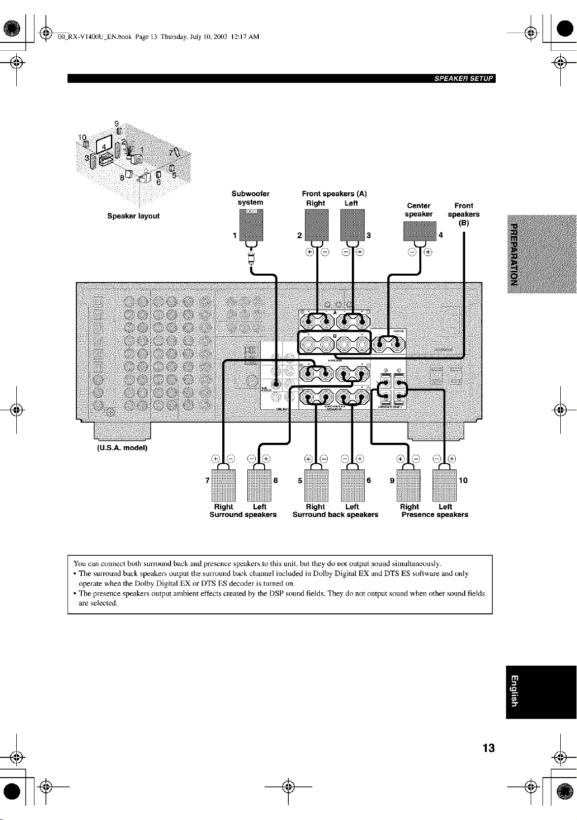
Speakerlayout
Subwoofer Front speakers (A)
system Right Left
2 3
Center Front
speaker speakers
(B)
+
(U.S.A. model)
i;iiiil
+
10
Right Left Right Left Right Left
Surround speakers Surround back speakers Presence speakers
You can com_ect both surround back and presence speakers to this unit, but they do not output s(_und simultaneously.
• The surround back speakers output the surround back channel included in Dolhy Digital EX and DTS ES so_ware and only
operate when the Dolby Digital EX or DTS ES decoder is turned on.
• The presence speakers output ambient eftects created by the DSP sound fields. They do not output sound when other sound fields
are selected.
13
_ @00 RX-VI40(IU EN.book Page 14 Thursday, July 10, 20(13
12:17 AM
• FRONT terminals
Connect one or two speaker syslems to these lerminals. If
you use only one speaker syslem, connect it Io either of
the FRONT A or B lerminals.
• CENTER terminals
Connect a center speaker to these terminals.
• SURROUND terminals
Connect surround speakers to these terminals.
The Canada model cannot output to two separate speaker systems
simuhaneously.
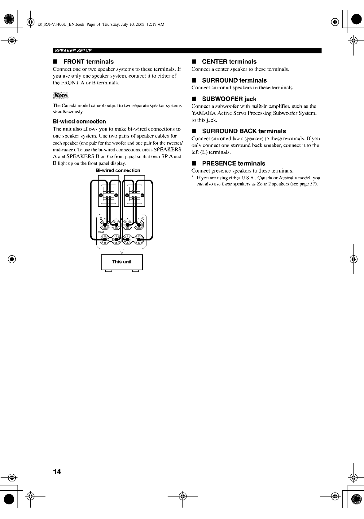
Bi-wired connection
The unit also allows you to make bi-wired connections to
one speaker syslem. Use two pairs of speaker cables for
each speaker (one pair fi_r the woofer and one pair fi_r the tweeter/
mid=range). To use the bi=wired connections, press SPEAKERS
A and SPEAKERS B on the t?ont panel so that both SPA and
B light up on the front panel display.
Bi-wired connection
V
This unit
• SUBWOOFER jack
Connect a subwoofer wilh buill=in amplifier, such as the
YAMAHA Active Servo Processing Subwoofer System,
to this jack.
• SURROUND BACK terminals
Connect surround back speakers to these terminals. If you
only connect one surround back speaker, connect it Io Ihe
lefl (L) terminals.
• PRESENCE terminals
Connect presence speakers 1o these lerminals.
* If you are using either U.S.A., Canada or Australia model, you
can also use these speakers as Z_me 2 speakers (see page 57).
14
_ @0(! RX-VI400U EN.book Page 15 Thursday, July 10, 20(13
12:17 AM
+
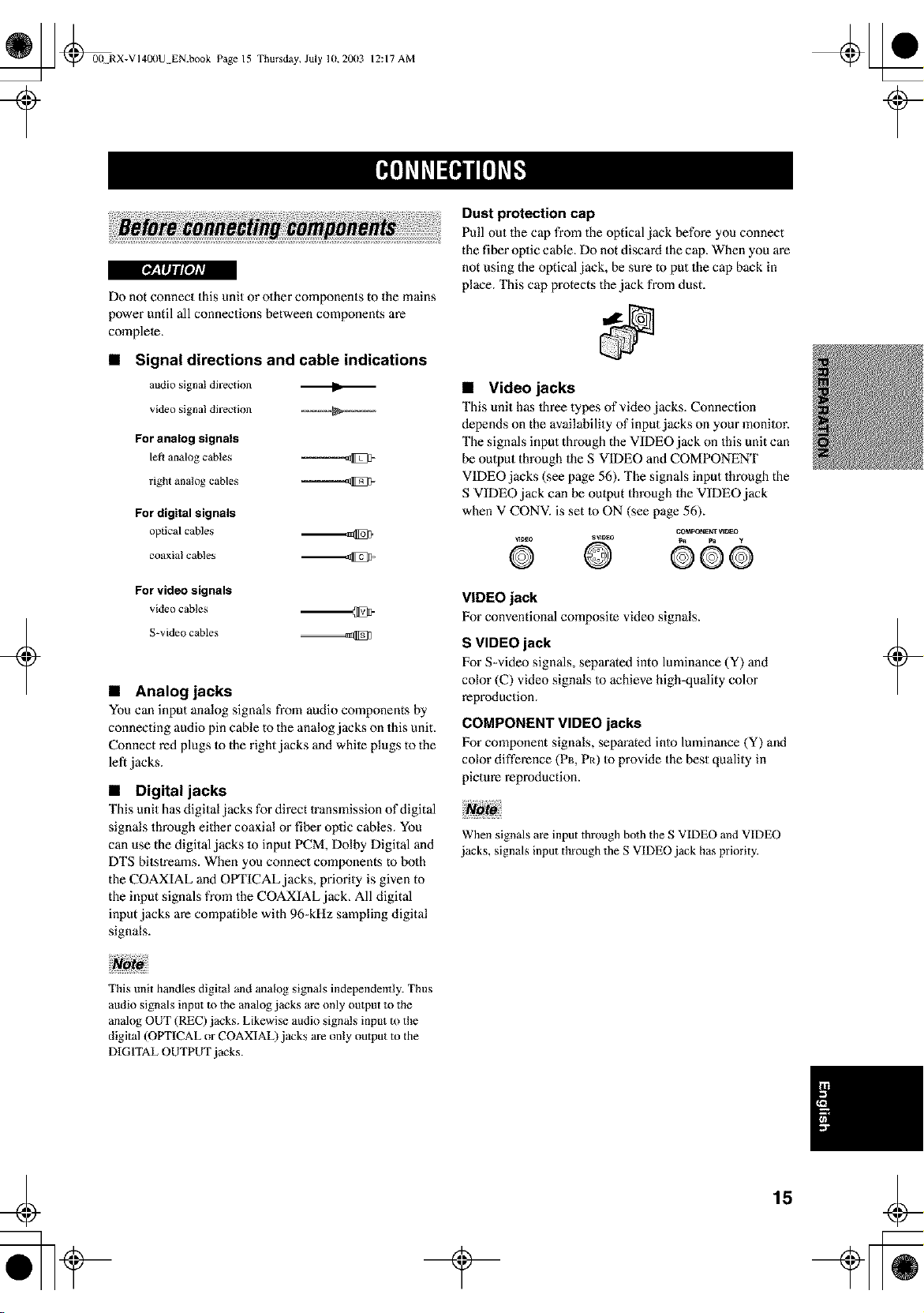
Do not connect this unit or other components to the mains
power until all connections between components are
complete.
• Signal directions and cable indications
audio signal direction I1_
video signal direction
For analog signals
left analog cables
right analog cables
For digital signals
oplical cables
coaxialcahles
For video signals
videocables
S-video cables
• Analog jacks
You can input analog signals from audio components by
connecting audio pin cable to the anMog jacks on this unit.
Connect red plugs Io the right jacks and white plugs to the
left jacks.
• Digital jacks
This unit has digital jacks for direct lransmission of digital
signals through either coaxial or fiber oplic cables. You
can use the digital jacks m input PCM, Dolby Digital and
DTS bitstreams. When you connect components to bolh
the COAXIAL and OPTICAL jacks, priority is given to
the input signals from the COAXIAL jack, All digital
input jacks are compatible with 96-kHz sampling digital
signals.
Dust protection cap
Pull out the cap from the optical jack before you connect
the fiber oplic cable. Do not discard the cap. When you are
not using the optical jack, be sure m put the cap back in
place. This cap protects the jack from dust.
• Video jacks
This unit has lhree types of video jacks. Connection
depends on the availability of input jacks on your monitor.
The signals input through the VIDEO jack on this unit can
be output through the S VIDEO and COMPONENT
VIDEO jacks (see page 56). The signals input through the
S VIDEO jack can be oulput through the VIDEO jack
when V CONV. is set to ON (see page 56).
C_PONE_VI_O
®.......@ 00o
VIDEO jack
For conventional composite video signals.
S VIDEO jack
For S=video signals, separated into luminance (Y) and
color ((2) video signals to achieve high-quality color
reproduction.
COMPONENT VIDEO jacks
For component signals, separated into luminance (Y) and
color difference (P_, Pt0 Io provide the best quality in
picture reproduction.
When signals are input through both the S VIDEO and VIDEO
jacks, signals input through the S VIDEO jack has priority.
+
This unit handles digital and analog signals independently. Thus
audio signals input to the analog jacks are only output to the
analog OUT (REC) jacks. Likewise audio signals input m the
digital (OPTICAL or COAXIAL) jacks are only output to the
DIGITAL OUTPUT jacks.
¢
15
_ @00N RX-VI400U EN.book Page 16 Thursday, July 10, 20113
12:17 AM
roleJ_l_lgtlll_lE[OlLT/_
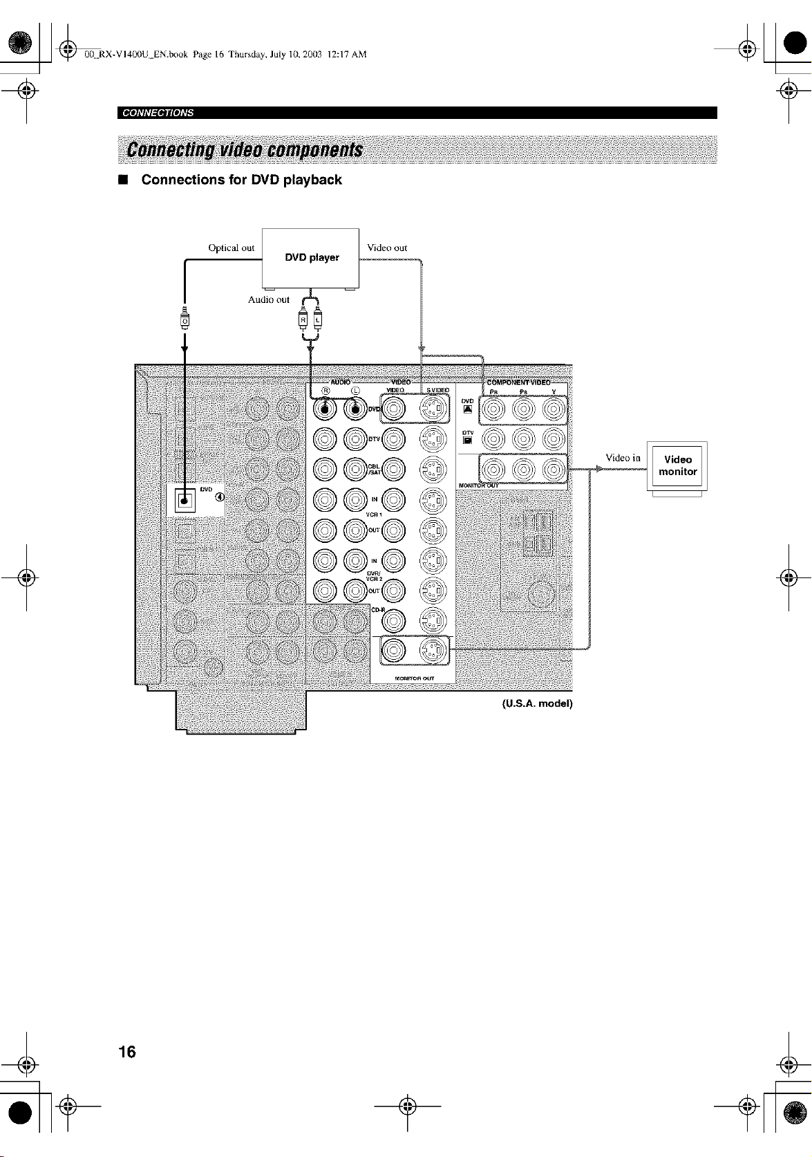
• Connections for DVD playback
Oplical out
DVD player
Video out
Videoin
(U.S.A. model)
16
_] @0(! RX-VI400U EN.book Page 17 Thursday, July 10, 20113
¢
12:17 AM
iph%_lagesl[ohTl
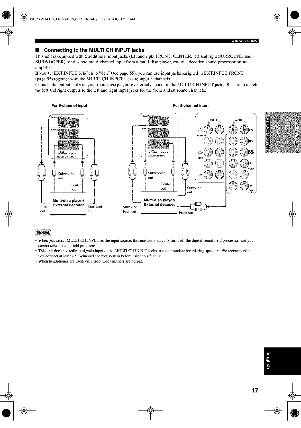
• Connecting to the MULTI CH INPUT jacks
This unit is equipped with 6 additional input jacks (left and right FRONT, CENTER, lefl and right SURROUND and
SUBWOOFER) for discrete multi-channel input from a multi-disc player, exlernal decoder, sound processor or pre-
amplifier,
If you set EXT.INPUT 6ch/8ch to "8ch" (see page 55), you can use input jacks assigned in EXTINPUT FRONT
(page 55) together with Ihe MULTI CH INPUT jacks to input 8 channels.
Connect the output jacks on your multi-disc player or external decoder to the MULTI CH INPUT jacks. Be sure to match
the left and right outputs to the left and right input jacks for the front and sun'ound channels.
÷
For 6-channelinput
Subwool_r @@
I
Multi-disc player/
Front External decoder Surround
For 8-channelinput
I ou, | ISorrou.d
Multi"disc playe_ _out
Surround External decoder _===_ _-_
bac J Fr_mt out _
AUDIO AOIJtO
@ © @ ©
©1©@
©©-
©©
• When you select MULTI CH INPUT as the input source, this unit automatically turns off the digital sound field processor, and you
cannot select sound field programs.
• This unit does not redirect signals input to the MULTI CH 1NPUT jacks to accommodate for missing speakers. We recommend that
you connect at least a 5.1-channel speaker system before using this teatm'e.
• When headphones are used, only fl'ont L/R channels are output.
¢
17
_ @00 RX-VI400U EN.book Page 18 Thursday, July 10, 2003
¢
12:17 AM
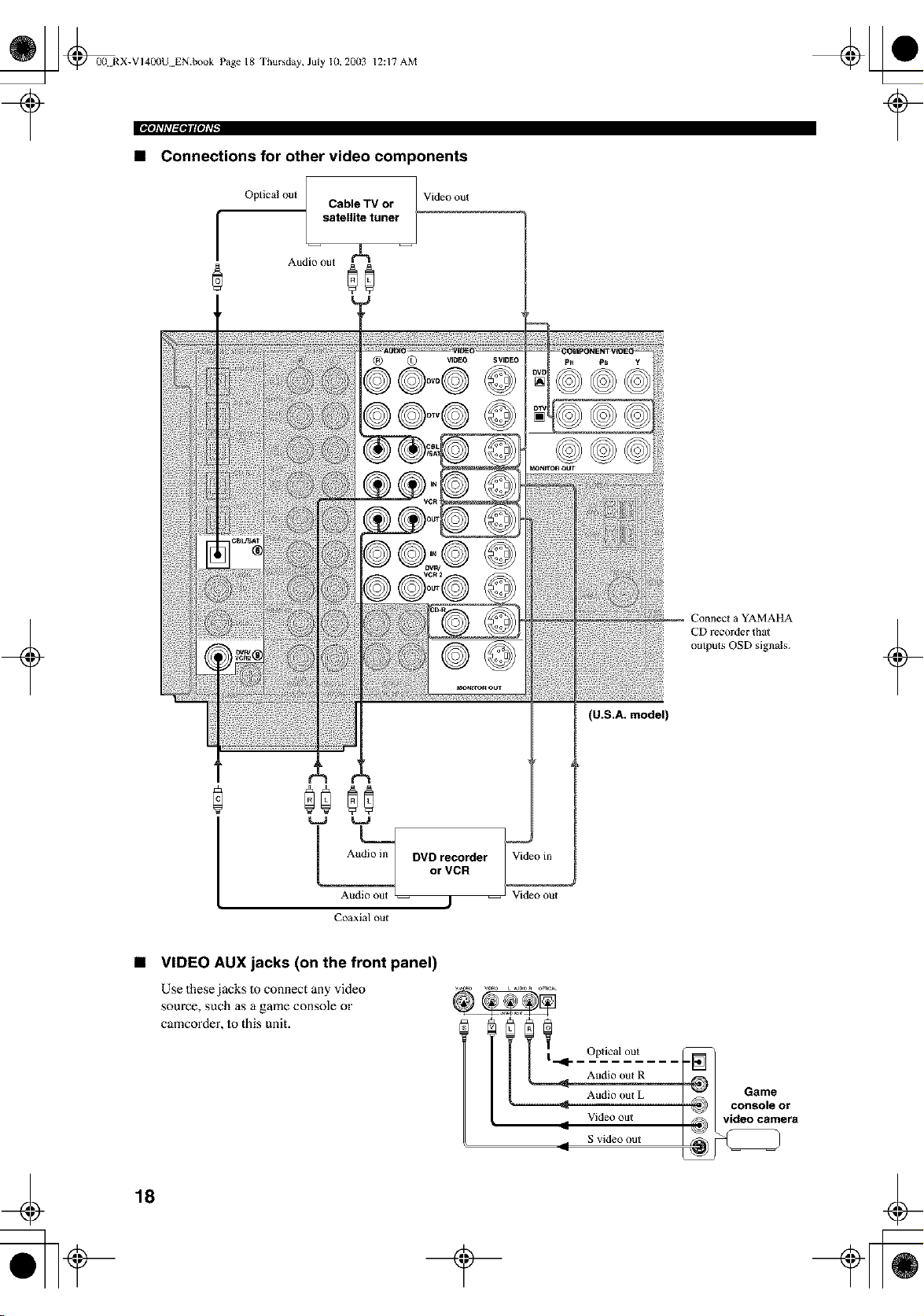
• Connections for other video components
I
Optical out
Cable TV or
satellite tuner
I
Audio out
®0
Video out
+
®0
Audio in DVD recorder
Aui_ or VCR
-- j
Coaxial out
Videoin
Video out
(U.S.A. model)
a YAMAI tA
CD recorder that
outputs OSD signals.
+
¢
• VIDEO AUX jacks (on the front panel)
Use these jacks 1oconnect any video
source, such as a game console or
camcorder, Io this unit.
l _1_ Optical out
Audio out R
Audio OUt L
Video out
11
S video out
18
_J Game
__ vi(d_nsc°/e°rra
_ [_ @0(! RX-VI400U EN.book Page 19 Thursday, July 10, 20113
?
12:17 AM
Iph%_l_fOlll[OhTl
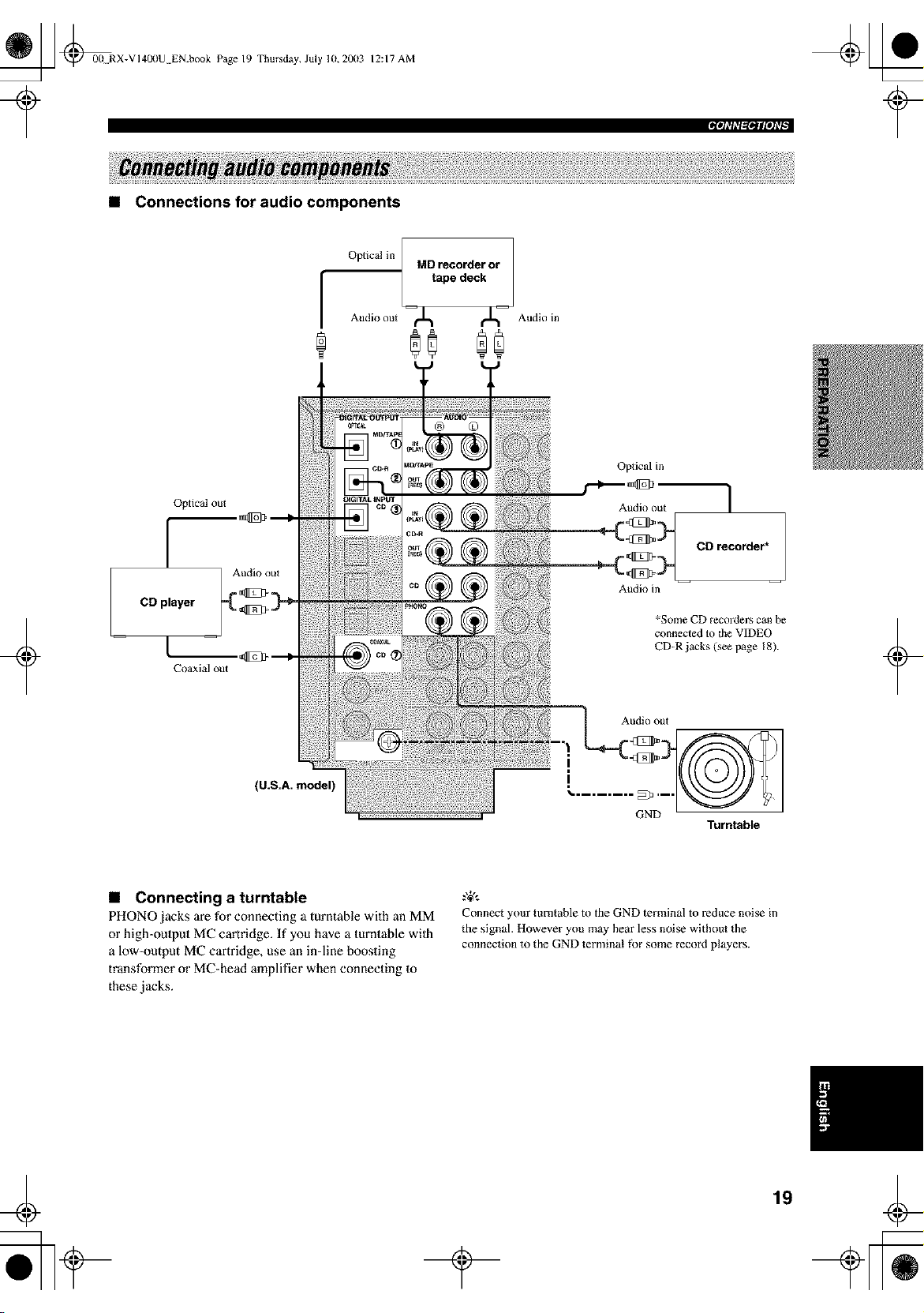
• Connections for audio components
F
Optical in / MD recorder or
/
tape deck
Audio out --¢J_ i_-- Audio in
®0 00
+
Optical out
[
CDplayer
Coaxial out
(U.S.A. model)
Oplical in
Audio out 1
_ CD recorder*
Audio in
*Some CD recorders can be
connected to the VIDEO
CD-R jacks (see page 18).
Audio out
D 3
'-........
Turntable
+
• Connecting a turntable
PHONO jacks are for connecting a turntable with an MM
or high-oulput MC cartridge. If you have a turntable wilh
a low-output MC cartridge, use an in-line boosting
transformer or MC-head amplifier when connecting 1o
these jacks.
g+,.
Connect your turntable to the GND terminal to reduce noise in
the signal. However you may hear less noise without the
connection to the GND terminal fbr some record players.
4
19
_ @0(ERX-VI400U EN.book Page 20 Thursday, July 10, 20(13
12:17 AM
• Connecting to an external amplifier
If you want to increase the power output to the speakers,
or want Io use another amplifier, connect an extex_nal
amplifier Io the PRE OUT jacks as follows.
• When audio pin plugs are connected to the PRE OUT jacks fk_r
output to an external amplifier, it is not necessary to use the
corresponding SPEAKERS terminals. Set the volume of the
amplifier connected to this unit to the maximum.
• The signal output through the FRONT PRE OUT and CENTER
PRE OUT jacks are affected by the TONE CONTROL settings.
• Signals will only be output fi'om the FRONT PRE OUT jacks
when SPEAKER A is turned off with ZONE B selected for SP
B SET (see page 57).
_ooo,1
5"-- _°°°'3
_ooo,4
+
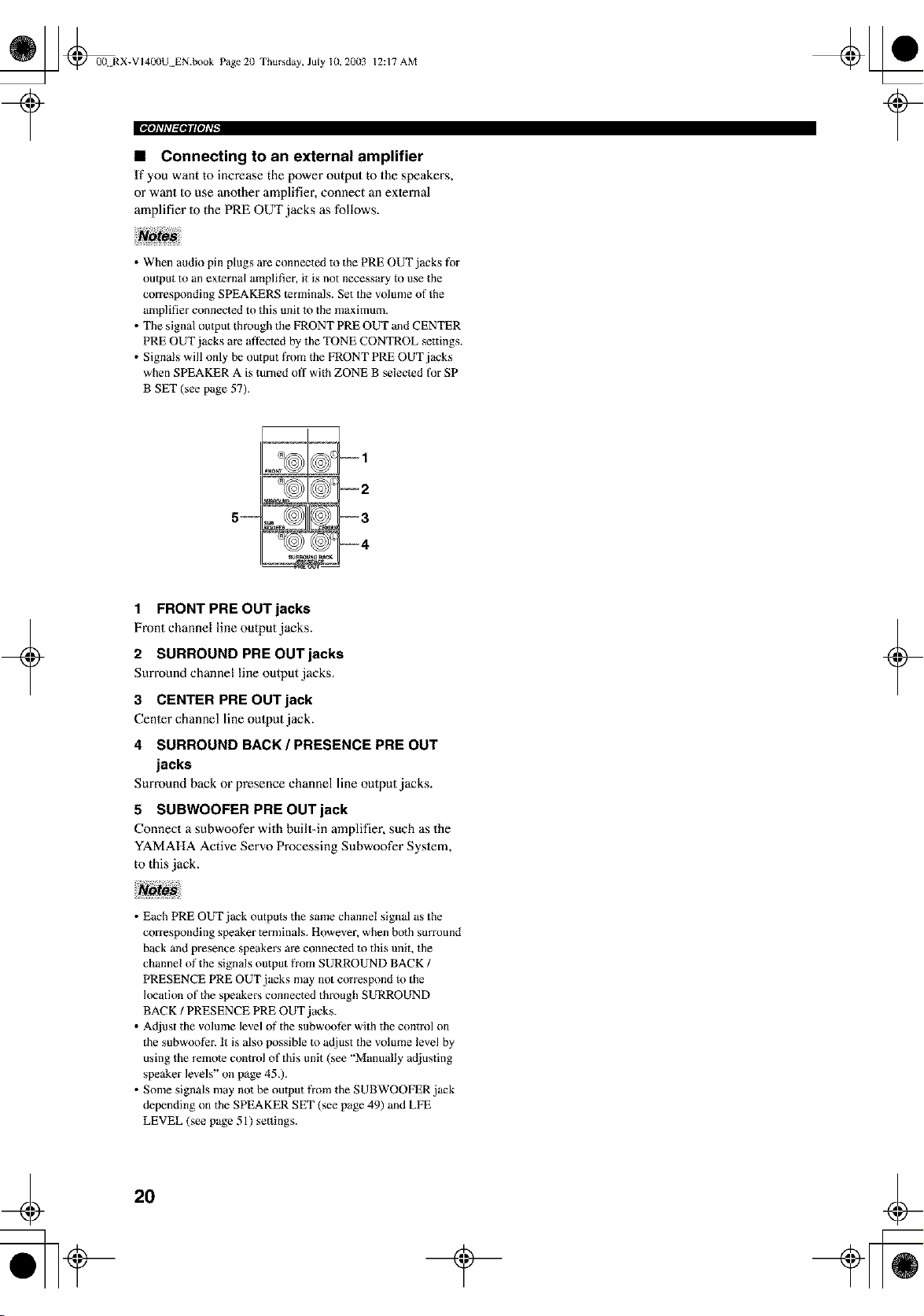
1 FRONT PREOUTjacks
Front channelline outputjacks.
2 SURROUND PREOUTjacks
Surround channelline outputjacks.
3 CENTER PRE OUT jack
Cenler channel line output jack.
4 SURROUND BACK / PRESENCE PRE OUT
jacks
Surround back or presence channel line output jacks.
5 SUBWOOFER PRE OUT jack
Connect a subwoofer with buill-in amplifier, such as the
YAMAHA Active Servo Processing Subwoofer Syslem,
to this jack.
+
• Each PRE OUT jack outputs the same channel signal as the
corresponding speaker terminals. However, when both surround
back and presence speakers are connected to this unit, the
channel of the signals output fi'om SURROUND BACK /
PRESENCE PRE OUT jacks may not corresp_)nd _o the
location of the speakers connected through SURROUND
BACK / PRESENCE PRE OUT jacks.
• Adjust the volume level ol_"the subwoof_r with the control on
the subwoof?r. It is also possible to adjust the volume level by
using the remote control of this unit (see "Manually adjusting
speaker levels" on page 45.).
• Some signals may not he output fi'om the SUBWOOFER jack
depending on the SPEAKER SET (see page 49) and LFE
LEVEL (see page 51) settings.
2O
_ _00 RX-VI400U EN.book Page 21
Thursday, July 10,2003 12:17 AM
Iph%,l_Btll[OhTl
+
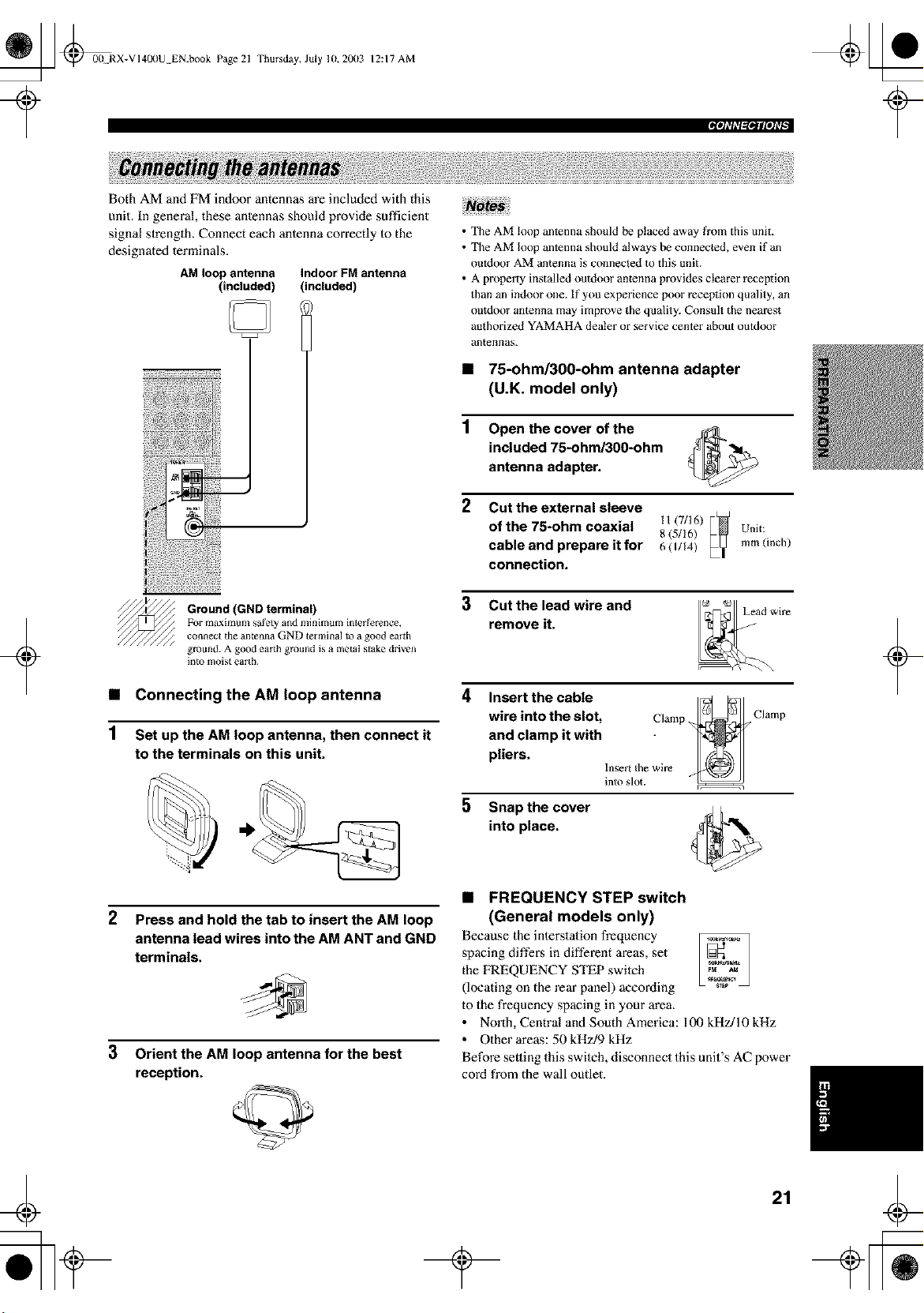
Both AM and FM indoor antennas are included with this
unit. In general, these anlennas should provide sufficient
signal strength. Connect each anlenna correctly Io the
designated terminals.
AM loop antenna Indoor FM antenna
(included) (included)
Ground (GND terminal)
Fur maxintum safety and ndnimum inler ference,
connect die antenna GND tel mina] Io a good eardl
ground. A good earth ground is a metal stake driven
]ntu moist earth.
• Connecting the AM loop antenna
1 Set up the AM loop antenna, then connect it
to the terminals on this unit.
2 Press and hold the tab to insert the AM loop
antenna lead wires into the AM ANT and GND
terminals.
3 Orient the AM loop antenna for the best
reception.
• The AM loop antenna should be placed away fl'om this unit.
• The AM loop antenna should always be connected, evenif a_
outdoor AM antenna is connected to this unit.
• A property installedoutdoor antenna provides clearer reception
than an indoor one. ff you experience poor reception quality, an
outdoor antenna may improve the quality. Consuh the nearest
authorized YAMAHA dealer or service center about outdoor
al/|e]!]las.
• 75-ohm/300-ohm antenna adapter
(U.K. model only)
1 Open the cover of the
included 75-ohm/300-ohm
antenna adapter.
2
Cut the external sleeve
of the 75-ohm coaxial _i (7/16)
8 (5116) Unit:
cable and prepare it for 6 (I/14) mm (inch)
connection.
3 Cut the lead wire and
remove it.
4
5
Insert the cable _ _
wire into the slot, Clamp _ Clamp
and clamp it with
pliers.
Insert the wire
into slot.
Snap the cover
into place.
• FREQUENCY STEP switch
(General models only)
Because the interstation frequency
spacing differs in different areas, set
the FREQUENCY STEP switch
(locating on the rear panel) according
to the frequency spacing in your area.
• North, Central and South America: 100 kHz/10 kHz
• Other areas: 50 kHz/9 kHz
Before setting this swilch, disconnect this unit's AC power
cord from the wall outlet.
+
21
_ @00 RX-VI400U EN.book Page 22 Thursday, July 10, 20(13
12:17 AM
rolo]_l_lgglStlgOlLql
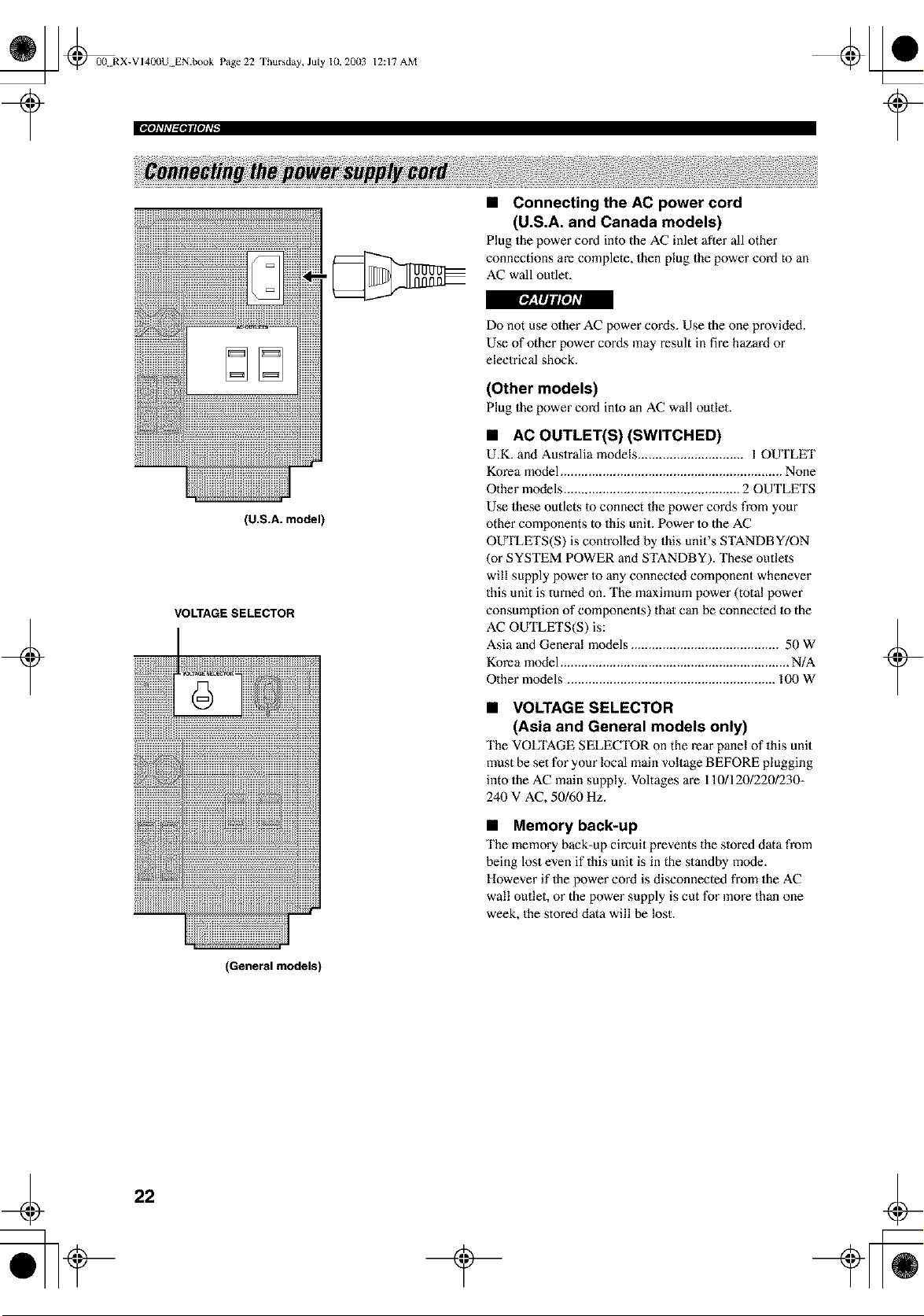
• Connecting the AC power cord
(U.S.A. and Canada models)
Plug the power cord into the AC inlet after all other
connections are complete, then plug the power cord to an
AC wall outlet.
+
(U.S.A. model)
VOLTAGE SELECTOR
Do not use other AC power cords. Use the one provided.
Use of other power cords may result in fire hazard or
electrical shock.
(Other models)
Plug the power cord into an AC wall outlet.
• AC OUTLET(S) (SWITCHED)
U.K. and Auslralia models .............................. 1 OUTLET
Korea model ............................................................... None
Other models .................................................. 2 OUTLETS
Use these outlets to connect the power cords from your
other components to this unit. Power to the AC
OUTLETS(S) is controlled by this unit's STANDBY/ON
(or SYSTEM POWER and STANDBY). These outlets
will supply power Io any connected component whenever
this unit is turned on. The maximum power (tolal power
consumption of components) that can be connected to the
AC OUTLETS(S) is:
Asia and General models .......................................... 50 W
Korea model ................................................................. N/A
Other models ........................................................... 100 W
• VOLTAGE SELECTOR
(Asia and General models only)
The VOLTAGE SELECTOR on the rear panel of this unit
must be set for your local main voltage BEFORE plugging
into the AC main supply. Voltages are 1101120/220/230-
240 V AC, 50/60 Hz.
• Memory back-up
The memory back-up circuit prevents the slored data from
being lost even if this unit is in the standby mode.
However if the power cord is disconnected from the AC
wall outlet, or the power supply is cut for more than one
week, the stored data will be lost.
+
(General models)
22
_ L] @00 RX-VI40(IU EN.book Page 23 Thursday, July 10, 20(13
12:17 AM
Ipl_%,l_*lll[OATl
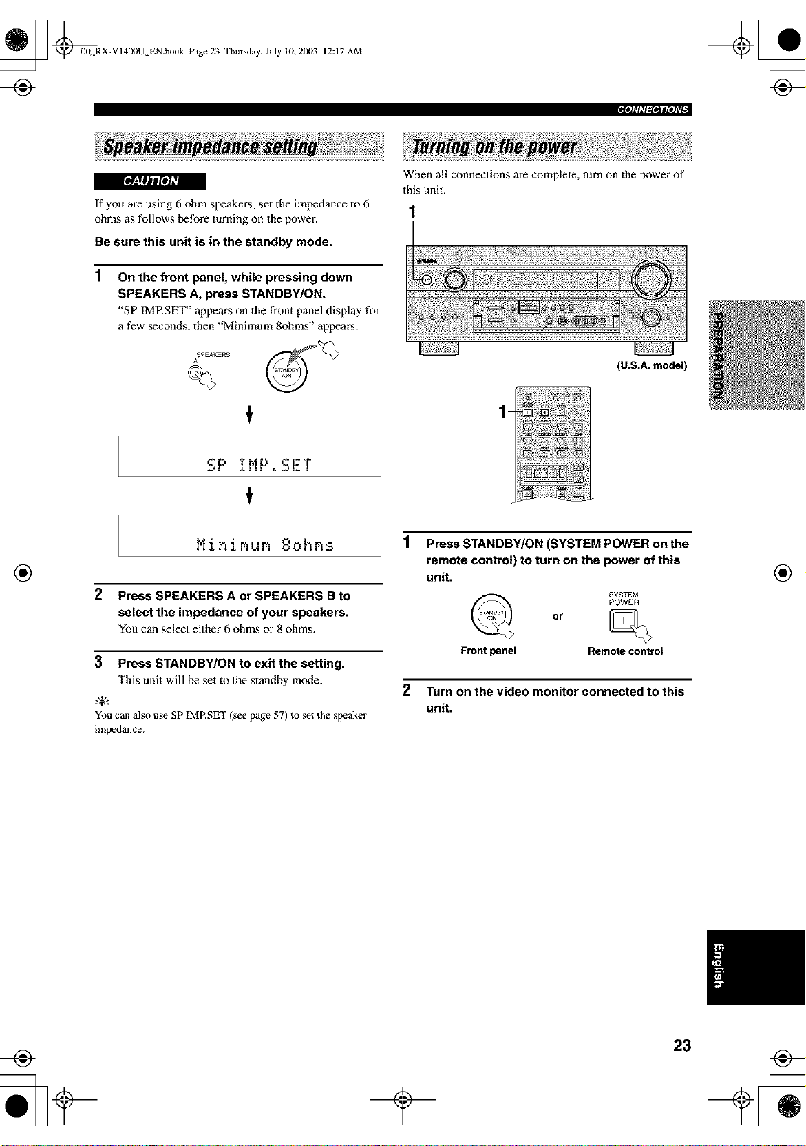
[*_I#JuffeJ_
If you are using 6 ohm speakers, set the impedance to 6
ohms as follows before turning on the power.
Be sure this unit is in the standby mode.
1
On the front panel, while pressing down
SPEAKERS A, press STANDBY/ON.
"SP IMP.SET" appears on the front panel display for
a few seconds, then "Minimum 8ohms" appears.
ASPEAKEAS
When all connections are complete, turn on the power of
this unit.
-
_--F= j.!!F = =-r'T
1
N : " =-'- .'. Z -
2 Press SPEAKERS A or SPEAKERS B to
select the impedance of your speakers.
You can select either 6 ohms or 8 ohms.
+
3 Press STANDBY/ON to exit the setting.
This unit will be set to the standby mode.
.%,:
You can also use SP IMRSET (see page 57) to set the speaker
impedance.
(U.S.A. model)
Press STANDBY/ON (SYSTEM POWER on the
remote control) to turn on the power of this
unit.
SYSTEM
POWER
or
Frontpanel Remotecontrol
2 Turn on the video monitor connected to this
unit.
+
23
_ @0(t RX-VI40(IU EN.book Page 24 Thursday, July lU, 20(13
12:17 AM
+
This receiver employs Yamaha Parametric Room Acoustic
Oplimizer (YPAO) technology which lets you avoid
troublesome lislening-based speaker setup and achieves
highly accurate sound adjustments. The supplied
optimizer microphone collects and analyzes the sound
your speakers produce in your actual listening
environment.
.,+,.
The basic setup feature (page 28) is usetul if you want to set up
your system quickly and with minimal e[_._rt. However, we
recommend that you come back and perform auto setup later to
take advantage of YPAO and enjoy even higher fidelity.
• Loud test tones are output during the auto setup procedure.
Please be ready!
• If aura setup stops and error messages appear on the OSD,
_\)llow the troubleshoming on page 27.
YPAO performs the following checks and makes
appropriate adjustments to give you the best possible
sound from your system.
WIRING
Checks which speakers are connected and the polarity of
each speaker.
DISTANCE
Checks the distance of each speaker from the listening
position and adjusts the timing of each channel.
SIZE
Checks the speaker's frequency response and sets the
appropriate low frequency crossover for each channel.
EQUALIZING
Adjusts frequency and levels of each channel's parametric
equalizer to reduce coloralion across the channels and
create a cohesive sound field. This is particularly
important if you use different brands or sizes of speakers
for some channels or have a room with unique sonic
characteristics.
LEVEL
Checks and adjusts the sound level (volume) of each
speaker.
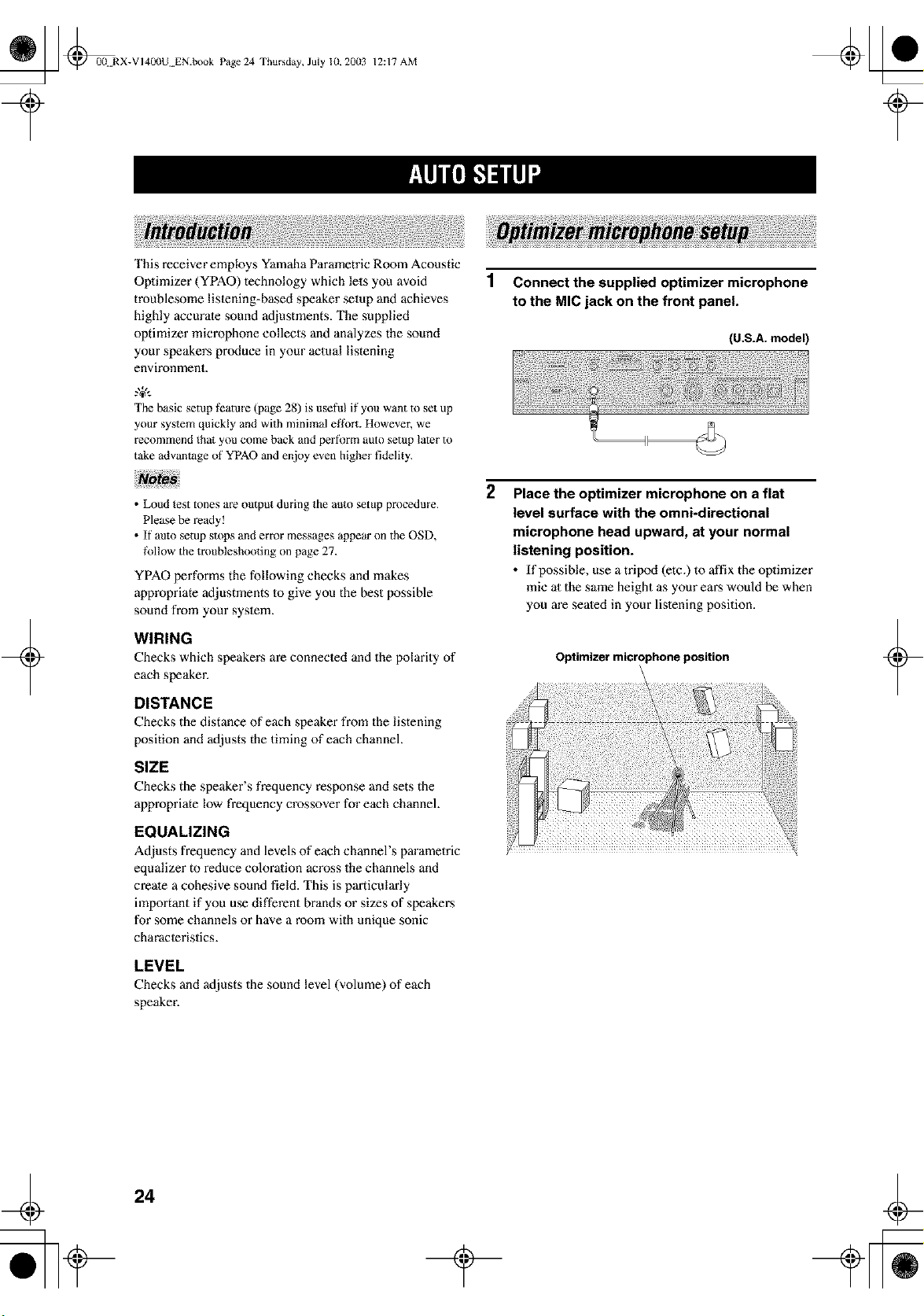
1 Connect the supplied optimizer microphone
to the MIC jack on the front panel.
(U.S.A. model)
2
Place the optimizer microphone on a flat
level surface with the omni-directional
microphone head upward, at your normal
listening position.
• If possible, use a tripod (etc.) to affix the optimizer
mie al the same height as your ears would be when
you m'e seated in your listening position.
Optimizer microphone position
\
+
24
_ _0(! RX-VI400U EN.book Page 25 Thursday, July 10, 20(13
?
12:17 AM
For best resulls, make sure the room is as quiet as possible
during the aulo setup procedure. If there is Ioo much
ambient noise, the results may not be salisfaclory.
g&.
If your subwooter can adjust the output volmne and the crossover
frequency, set the volume to about half way (or slightly less) and
set the crossover frequency to the maximum.
1
2
Switch on the receiver and video monitor.
Make sure the OSD is displayed.
Press AMP to select the AMP mode, then
press SET MENU to enter the SET MENU.
St_ENU
then
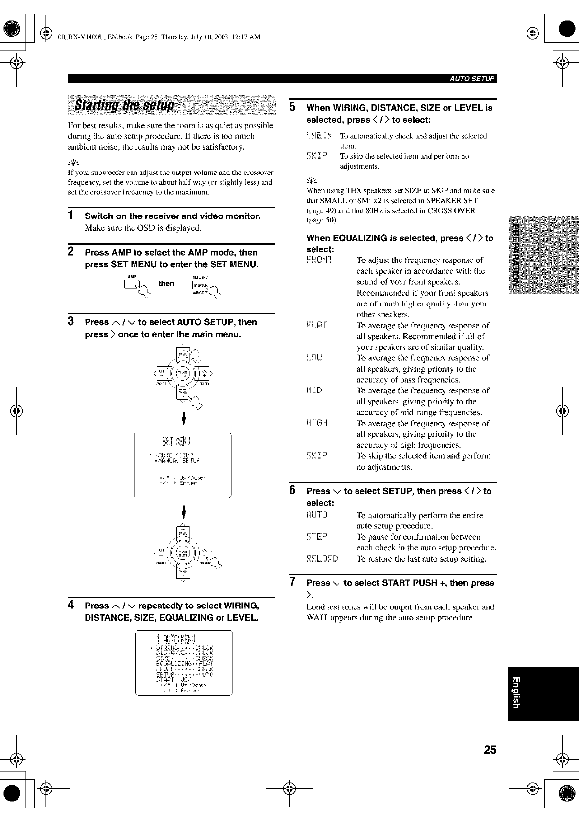
3 Press A / V to select AUTO SETUP, then
press > once to enter the main menu.
+
€
_i- T ]_
D_! Hr-hU
÷ ,_UIO _.:,fi:fUP
• M_NUAL _ fi:IUP
€
4
Press A / V repeatedly to select WIRING,
DISTANCE, SIZE, EQUALIZING or LEVEL.
HUiU:H_i]U
L'_IST_NCg • __C_ECK
glzE ..... CHECK
E,., _LI_ IN,_ , L_T
LE_gL..... CHECK
SETUP....... _uYO
START F'HSH +
5
6
7
When WIRING, DISTANCE, SIZE or LEVEL is
selected, press ( / > to select:
CHECK To automatically check and adjust the selected
item.
S_::I P To skip the selected item and perform no
adjustments.
g&.
When using THX speakers, set SIZE m SKIP and make sure
that SMALL or SMLx2 is selected in SPEAKER SET
(page 49) and that 80Hz is selected in CROSS OVER
(page 50).
When EQUALIZING is selected, press ( / > to
select:
FRONT "Ib adjust the frequency response of
each speaker in accordance with the
sound of your front speakers.
Recommended if your front speakers
m'e of much higher quality than your
other speakers.
FL_T "Ib average the frequency response of
all speakers. Recommended if all of
your speakers are of similar quality.
L01.,.I "Ib average the frequency response of
all speakers, giving priorily to the
accuracy of bass frequencies.
MI 0 "Ib average the frequency response of
all speakers, giving priorily to the
accuracy of mid-range frequencies.
H I GH To average the frequency response of
all speakers, giving priorily to the
accuracy of high frequencies.
Sk::IP To skip the seleeled item and perform
no adjustments.
Press v to select SETUP, then press < / > to
select:
nUTEI "Ib aulomatically perform the entire
aura setup procedure.
STEP "Ib pause for confirmation between
each check in the aulo setup procedure.
RELOAD "Ib restore the last auto setup setting.
Press v to select START PUSH +, then press
>.
Loud test tones will be output from each speaker and
WAIT appem_sduring the auto setup procedure.
+
25
_ _00 RX-VI400U EN.book Page 26 Thursday, July 10, 20(13
12:17 AM
_| Illli, lk,"t l_llIII 1-
If you selected AUTO in step 6
The RESUfff display appears for a few seconds after each
check, then settings of the next item will start, The
RESULT:EXIT display appeans after all items are set.
g+,.
You can display each result by pressing/-, once and pressing >
repeatedly berate exiting. Pressing v returns to the
RESUL_EXfT display.
8
To apply the changes, press < / > to select
SET, then press v to exit.
To cancel the auto setup procedure, press < /
> to select CANCEL, then press v to exit.
If you selected RELOAD in step 6
The RESULT:EXIT display appean_.
You can display each result by pressing/', once and pressing >
repeatedly before exiting. Pressing v returns to the
RESULT:EXIT display.
8 Press </ > to select SET, then press v to exit.
t
+
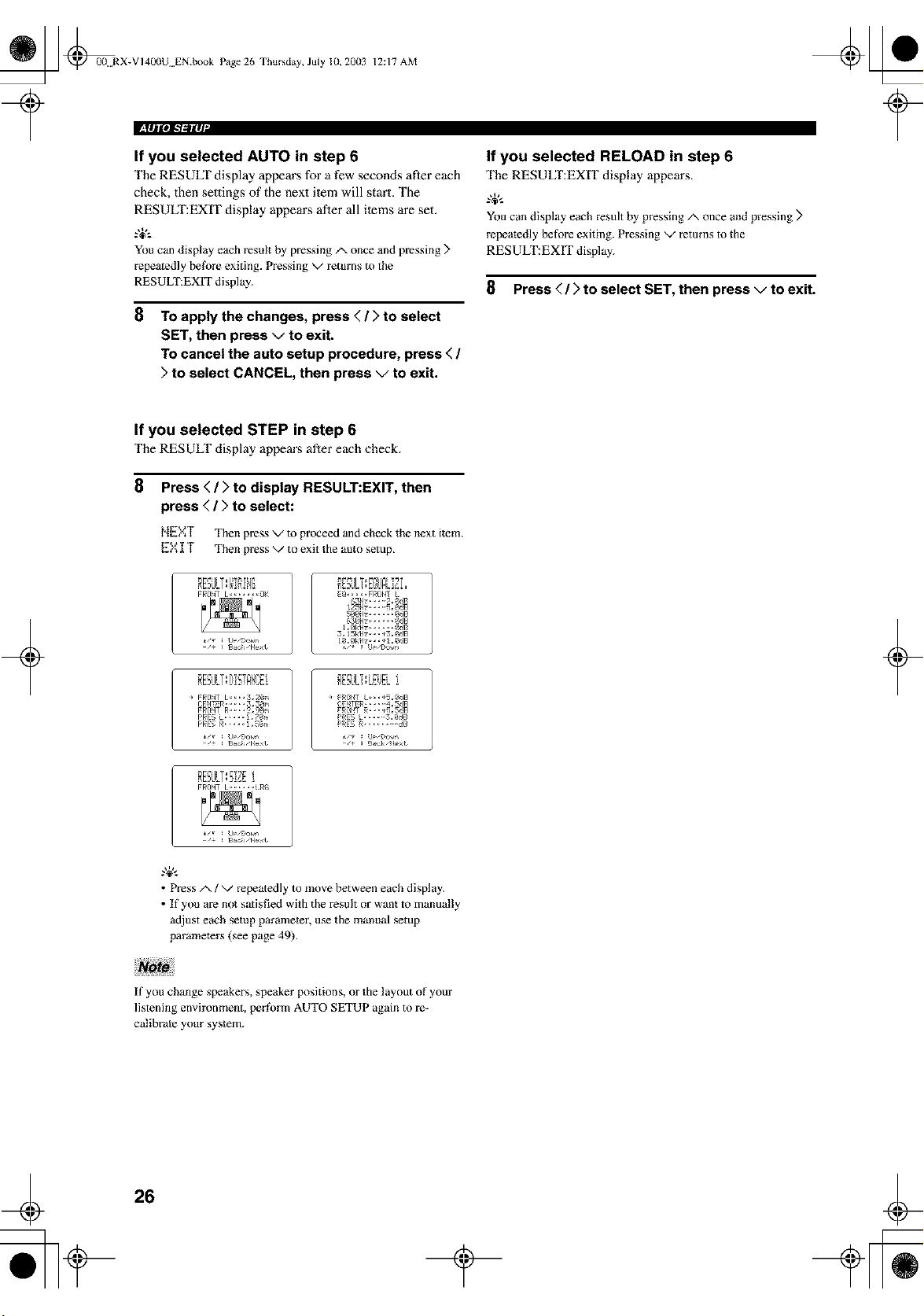
If you selected STEP in step 6
The RESULT display appears after each check.
8
Press < / > to display RESULT:EXIT, then
press < / > to select:
NEXT Then press v to proceed and check the next item.
EX IT Then press v to exit the auto setup.
3,15k_lz_,_*3,_gB
RESi.ILT:DET_k!i_i I RESVLT:LEi_ELi ]
CENTg_,,,,-4,SgB
F_fINT 1, •,,, i R_
• Press/', / v repeatedly to move between each display.
• If you am not satisfied with the result or want to manually
adjust each setup parameter, use the manual setup
parameters (see page 49).
+
If you change speakers, speaker positions, or the layout of your
listening environment, perR_rm AUTO SETUP again to re-
calibrate your system.
4
26
t
_ @0(! RX-VI400U EN.book Page 27 Thursday, July 10, 20(13
?
12:17 AM
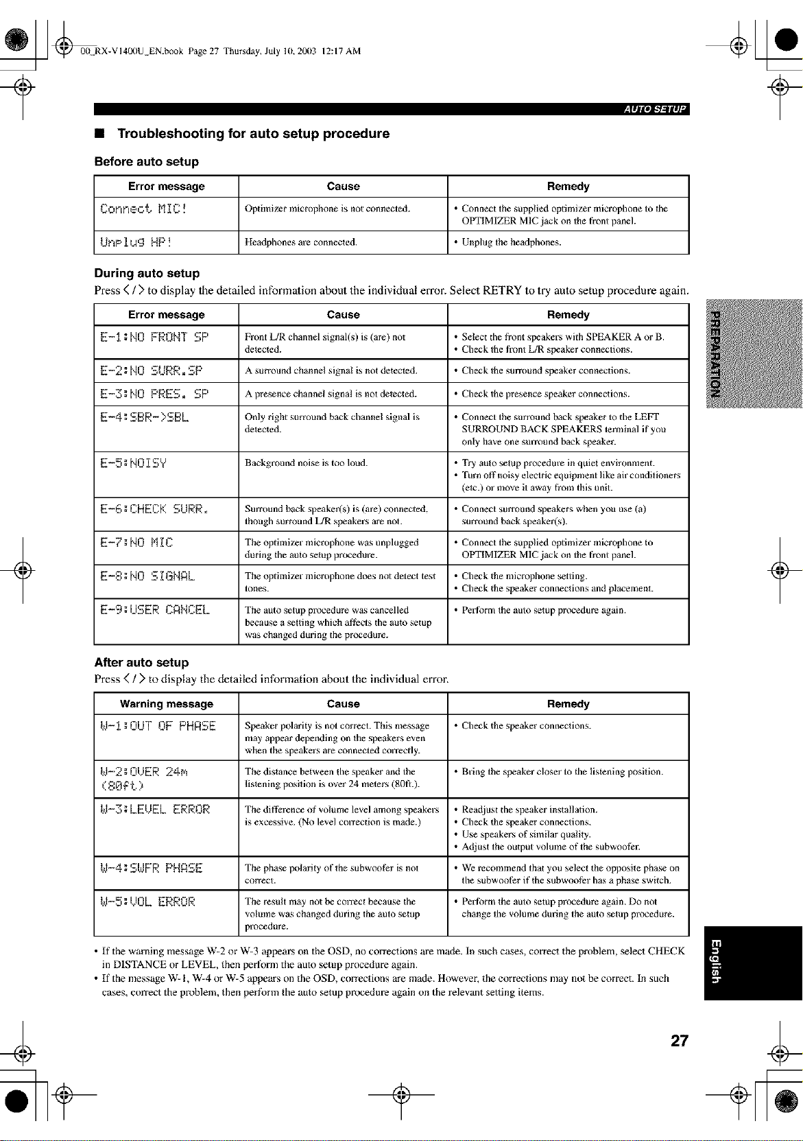
• Troubleshooting for auto setup procedure
Before auto setup
Error message Cause Remedy
Conneo_. M_C! Optiinizer microphone is not connected. • Connect the supplied optimizer microphone to the
OPTIMIZER MIC jack on the front panel.
driP 1Ug HP ! Headphones are connected. • Unplug the headphones.
During auto setup
Press (/) to display Ihe detailed information about the individual error. Select RETRY Io try aulo setup procedure again.
Error message Cause Remedy
E-1;N0 FRONT SP Front L/R channel signal(s/ is (are) not • Salect dle front speakers with SPEAKER A or B.
delected. • Check the front L/R speaker connections.
E-2; NO SURR. SP A surround channel signal is not detected. • Check the surround speaker connections.
E-3; NO PRES. SP A presence channel signal is not delected. • Check the presence speaker connections.
E-4; SBR- >SBL Only right surround back channel signal is • Connect the surround back speaker to the LEFT
delected. SURROUND BACK SPEAKERS terminal if you
only have one smTound back speaker.
E-5 ==NO [ SY Background noise is too loud. • Try auto setup procedm'e in quiet environment.
• Turn off noisy electric equipment like air conditioners
(etc.) or move it away from this unit.
E-_, ; CHEC[( SURe, Surround back speaker(s) is (are) connected, • Connect surround speakers when you use (a)
though surmtmd L/R speakers are not. surround back speaker(s).
E-_;NO N]_C Theoptiinizer microphone w_s unplugged • Connect the supplied optimizer microphone to
during the auto setup procedure. OPTIMIZER MIC jack on the front panel.
E-8:NO S[GHAL Theoptiinizermicrophonedoesnotdetecttes_ • Checkthemicrophonesetting.
tones. • Check the speaker connections and plaeemenL
E-9:USER CANCEL The auto setup procedure w_s cancelled • Perfbrmtheauto_tupprocedure_galn.
because a setting which af'tbcts the auto setup
was changed during lhe procedure.
After auto setup
Press ( / > to display the detailed information about the individual error.
Warning message Cause Remedy
W-1; OUT L'IFPHASE Speaker polarity is not correct. This message • Check the speaker connections.
may appear depending on the speakers even
when the speakers are connected correcdy.
kI-2g0/)ER 24N The distance between the speaker and the • Bring the speaker closer to the listening position.
( 8_ f'_.. ) lislening position is over 24 meters (80fl.).
kI-Z;LEUEL ERROR Thedifl_renceofvolumelevelamongspeakers • Readjust the speaker instatlation.
is excessive. (No level correction is made./ • Check the speaker connections.
• Use speakers of similar quality.
• Adjust the output volume of the subwoofer.
t.,.I-4; SI.dFR PHASE The phase polarity ofthesubwooti:r is not • We recommend that you select the oppesite phase on
correct, the subwoofer if the subwoofer has a phase switch.
kI-5;/)0L ERROR The result inky not be correct because the • Perfbrm the auto setup procedure again. Do not
volume was changed during the auto setup change the volume during the auto setup procedure.
procedure.
+ +
• If the warning message W-2 or W-3 appears on the OSD, no corrections are made. In such cases, correct the problem, select CHECK
in DISTANCE or LEVEL, then perfornl the auto setup procedure again.
• If the message W- I, W-4 or W-5 appears on the OSD, corrections are made. However, the corrections may not be correct. In such
cases, correct the problem, then perfk_rm the auto setup procedure again on the relevant setting items.
27
_ _00 RX-VI4L_IU EN.book Page 28 Thursday, July 10, 20(13
12:17 AM
+
The basic system parameters are set aulomalically when
you Pun auto setup (page 24). The basic settings are useful
if you want 1o quickly selup your speakers or Io manually
adjust some of the ilems set in auto setup.
.,+,.
• If you wish to configure the unit manually using more precise
adjustments, use the detailed parameters in the SOUND menu
(page 49) instead of using the BASIC menu.
• Altering any parameters in the BASIC menu wil! reset all
parameters in the SOUND menu.
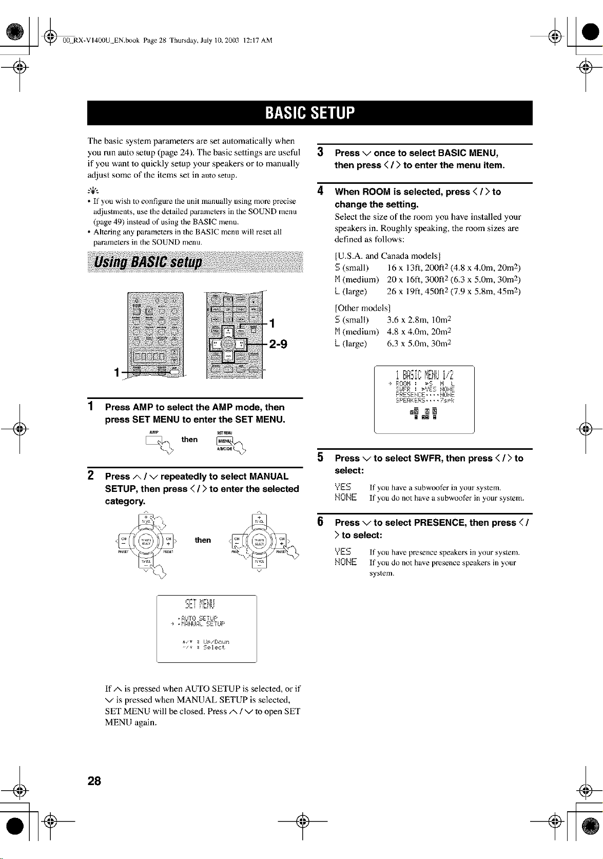
1
2
Press AMP to select the AMP mode, then
press SET MENU to enter the SET MENU.
S_T_
then
Press A / g repeatedly to select MANUAL
SETUP, then press </ > to enter the selected
category.
then
3 Press g once to select BASIC MENU,
then press < / > to enter the menu item.
4 When ROOM is selected, press < / > to
change the setting.
Select the size of the room you have installed your
speakers in. Roughly speaking, the room sizes are
defined as follows:
[U.S.A. and Canada models]
S (small) 16 x 13fl, 200!"12 (4.8 x 4.0m, 20m 2
M (medium) 20 x 16t"1, 300f12 (6.3 x 5.0m, 30m 2
k (large) 26 x 19fi, 450f12 (7.9 x 5.8m, 45rn2
]Other models]
S (small) 3.6 x 2.8m, lOre 2
M (medium) 4.8 x 4.Ore, 20m 2
k (large) 6.3 x 5.0m, 30m 2
.,r.=M._!l..nb'4U1,'.,:'
÷ ROOM : _S Fl L
S£1FR : _YES NONE
PRESENC:E.... NONE
SPEAKERS.... ?sPk
N NN N
5
6
Press v to select SWFR, then press < / > to
select:
YES If you have a subwoot?r in yore" system.
NONE If you do not have a subwoolbr in your system.
Press v to select PRESENCE, then press < /
> to select:
YES If you have presence speakers in your system.
_',IONE If you do not have presence speakers in your
system.
+
4, I rt_ttt
AUTO SETUP
÷ . MANUAL SETUP
IfA is pressed when AUTO SETUP is selecled, or if
v is pressed when MANUAL SETUP is selecled,
SET MENU will be closed. Press/x / v to open SET
MENU again.
28
_] @00N RX-VI400U EN.book Page 29 Thursday, July 10. 20(13
12:17 AM
+
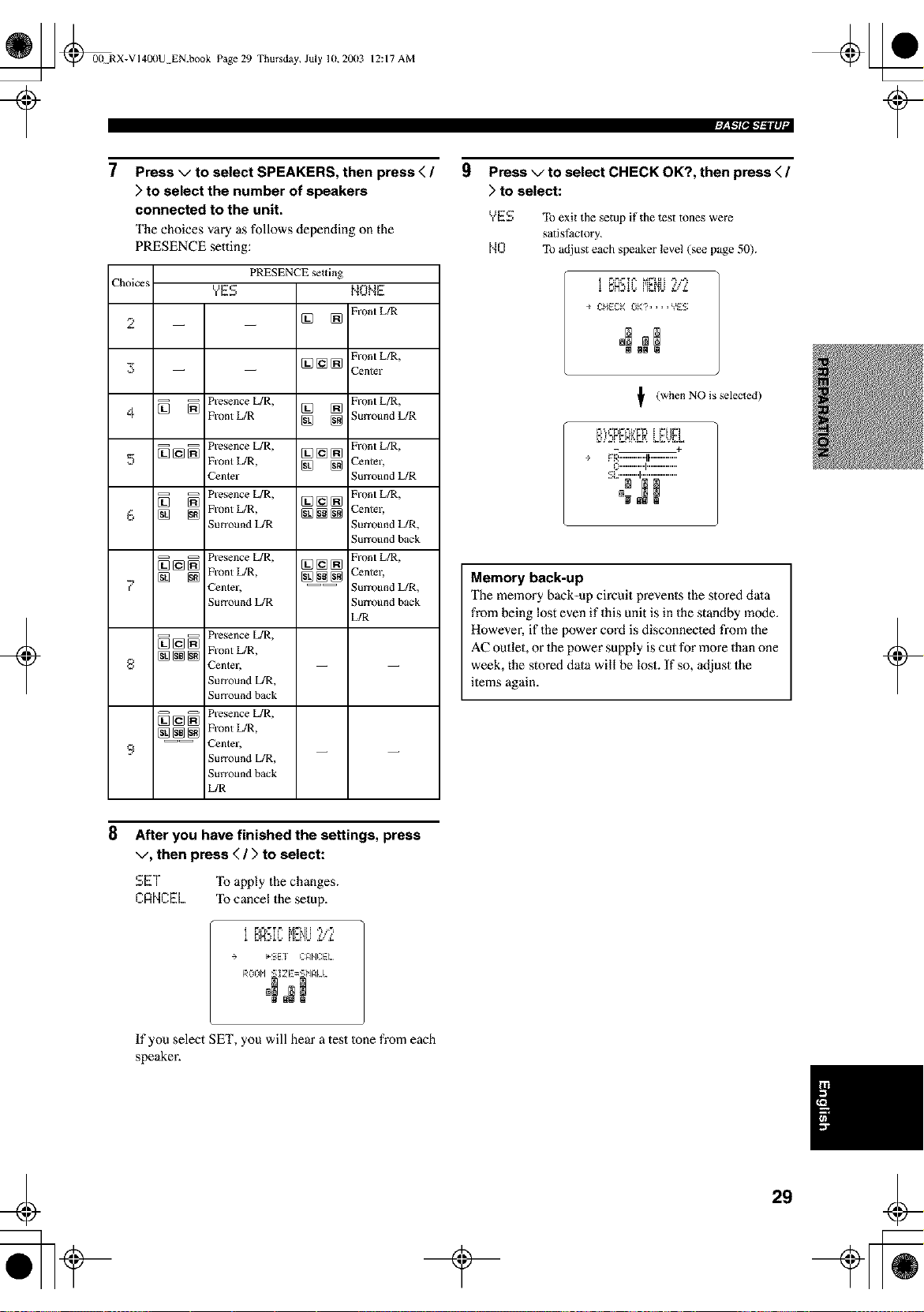
7
Press v to select SPEAKERS, then press < /
) to select the number of speakers
connected to the unit.
The choices vary as follows depending on the
PRESENCE setting:
Choices
2
3
4
5
6
f.
=
9
PRESENCE _tting
?E$
[] []
NONE
Front L/R
Front L/R,
[] [] [] Center
_] _ N'esence L/R, [] [] Front L/R,
Front L/R [] [] ;urroundL/R
-- -- Presence L/R, [_ [_ [_ Front L/R,
[] [] [] Front L/R, [] [] Center,
_Zenter ;urround L/R
_ Presence L/R, Front L/R,
[] [] Front L/R, [] [] []
[] [] [] [] [] Center,
urcound L/R Surround L/R,
;urround back
_ N'esence L/R, Front L/R,
[](e[] [](e[]
[] [] Front L/R, [] [] [] Center,
_Zenter, ---- Surround L/R,
urround L/R Surround back
L/R
_ Presence L/R,
[] [] [] Front L/R,
_ntelj
Surround L/R,
urround back
_] [] _ Presence L/R,
[] [] [] Front L/R,
---- _nter,
Surround L/R,
Surround back
L/R
9
Press v to select CHECK OK?, then press < /
) to select:
YES To exit the setup if the test tones were
satislSctory.
NO To adjust each speaker level (see page 50).
÷ CHECK0K?....Y_ES
NN N
_f (when NO is selected)
- +
÷ gh_.............tF..............
_:""""'1 ................
.........
B NN
Memory back-up
The memory back-up circuit prevents the stored dala
from being lost even if this unit is in the standby mode.
However, if the power cord is disconnecled from the
AC outlet, or 1he power supply is cut for more than one
week, the stored dala will be lost. If so, adjust the
ilems again.
t
+
8
After you have finished the settings, press
v, then press ( / > to select:
SET To apply the changes.
CRNCEL Ib cancel the setup.
i F,_t._. ' _t_"_[_[ ,'_ ,,'_
t tE_t tE _
+ _'SEf CFINCEL
If you select SET, you will hear a test tone from each
speaker.
29
t
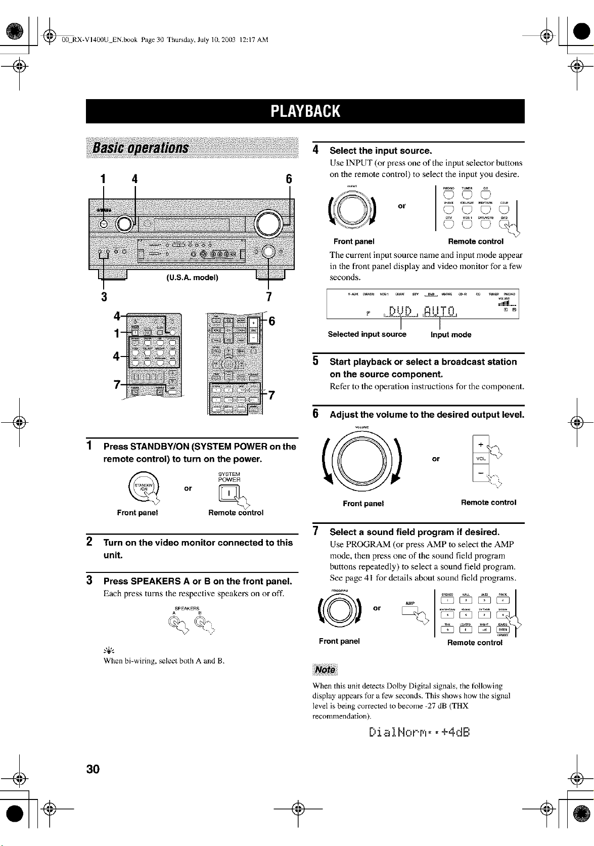
_ _0(t RX-VI4L_)U EN.book Page 30 Thursday, July 10, 2003
¢
12:17 AM
+
1 4 0
3
(U.S.A. model)
7
_6
:7
1
Press STANDBY/ON (SYSTEM POWER on the
remote control) to turn on the power.
SYSTEI_
POWER
or
Front panel Remote control
2 Turn on the video monitor connected to this
unit.
3 Press SPEAKERS A or B on the front panel.
Each press turns the respective speakers on or oft'.
ASPEAKERS B
When bi-wiring, select both A and B.
Select the input source.
Use INPUT (or press one of the input selector buttons
on the remote control) to select the input you desire.
O
Front panel
Go © o
Remote control
The current input source name and input mode appear
in the front panel display and video monitor for a few
seconds.
_!j!llll
r% t t _*,. =_= i i "T" t-
Selected input source Input mode
5 Start playback or select a broadcast station
on the source component.
Refer to the operation instructions for the component.
0
Front panel
Adjust the volume to the desired output level.
o
- ?
Remote control
7 Select a sound field program if desired.
Use PROGRAM (or press AMP m select the AMP
mode, then press one of the sound field program
buttons repealedly) Io select a sound field program.
See page 41 for details about sound field programs.
Front panel Remote control
+
When this unit detects Dolby Digital signals, the following
display appears for a few seconds. This shows how the signal
level is being corrected to become -27 dB (THX
recommendation).
O J,a iNorr,_.. +4dB
¢
30
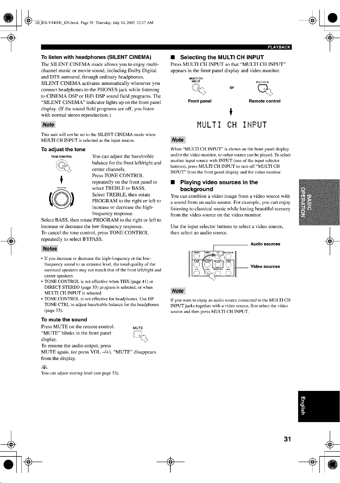
_ _RX-VI400U EN.book Page 31
Thursday, July lU, 2003 12:17 AM
To listen with headphones (SILENT CINEMA)
The SILENT CINEMA mode allows you m enjoy multi=
channel music or movie sound, including Dolby Digital
and DTS sun'ound, through ordinary headphones.
SILENT CINEMA activates automatically whenever you
connect headphones to the PHONES jack while listening
to CINEMA DSP or HiFi DSP sound field programs. The
"SILENT CINEMA" indicator lights up on the front panel
display. (If the sound field programs are oft', you listen
with normal stereo reproduction.)
This unit will not be set to the SILENT CINEMA mode when
MULTI CH INPUT is selected as the input source.
To adjust the tone
TONE CONTROL
O
You can adjust the bass/treble
balance for the front left/right and
cenler channels.
Press TONE CONTROL
repeatedly on the front panel to
select TREBLE or BASS.
Select TREBLE, then rotate
PROGRAM m the right or left to
increase or decrease the high-
frequency response.
Select BASS, then rotate PROGRAM to the right or left to
increase or decrease the low-frequency response.
"Ib cancel the tone control, press TONE CONTROL
repeatedly to select BYPASS.
• If you increase or decrease the high-frequency or the low-
frequency sound m an extreme level, the tonal quality of the
surround speakers may not match that of the front left/right and
center speakers.
• TONE CONTROL is not effective when THX (page 41) oz"
DIRECT STEREO (page 33) program is selected, or when
MULTI CH INPUT is selected.
• TONE CONTROL is not ef}?ctive tbr headphones. Use HP
TONE CTRL m adjust bass/treble balance fk_rthe headphones
(page 53).
To mute the sound
Press MUTE on the remote control. MUTE
"MUTE" blinks in the front panel
display.
"Ib resume Ihe audio output, press
MUTE again. (or press VOL -/+). "MUTE" disappem_s
from the display.
.,&.
You can adjust muting level (see page 53).
Frontpanel
• Selecting the MULTI CH INPUT
Press MULTI CH INPUT so that "MUff£1 CH INPUT"
appem's in the front panel display and video monitor.
MULYI CH
INPUT _d{JkTlgHIN
or
Remote control
t
_'_ ! I I "lrT =-'11 T L I r-= i i'lr
II=-=L- I J. =-'11 .LI'II =-= I
When "MULTI CH INPUT" is shown on the fi'ont panel display
and/or the video monitor, no other source can be played. To select
another input source with INPUT (one of the input selector
buttons), press MULTI CH INPUT to turn off"MULTI CH
INPUT" from the t}ont panel display and the video monitor.
• Playing video sources in the
background
You can combine a video image from a video source with
a sound from an audio source. For example, you can enjoy
lislening to classical music while having beautiful scenery
from the video source on the video monitor.
Use the input selector buttons to select a video source,
then select an audio source.
If you want to enjoy an audio source connected to the MULTI CH
INPUT jacks together with a video source, first select the video
source and then press MULTI CH INPUT.
31
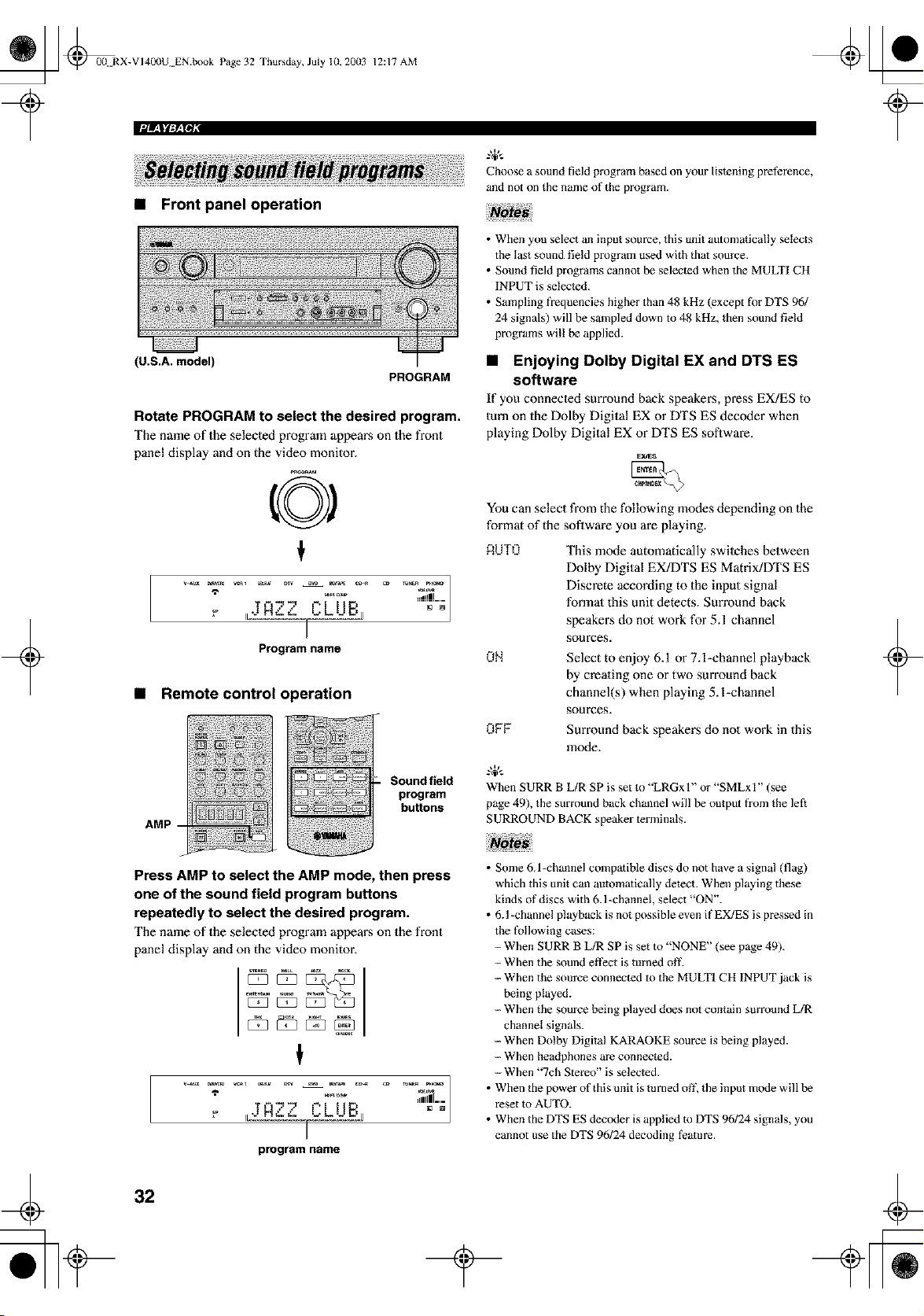
_ @0(! RX-VI400U EN.book Page 32 Thursday, July 10, 20(13
• Front panel operation
12:17 AM
PROGRAM
Choose a sound field program based on your listening preterence,
and not on the name of the program.
+
(U.S.A. model)
Rotate PROGRAM to select the desired program.
The name of the selected program appears on the front
panel display and on the video monitor.
A2'2' "LUBj
Program name
• Remote control operation
AMP
Sound field
program
buttons
• When you select an input source, this unit automatically selects
the last sound field program used with that source.
• Sound field programs cannot be selected when the MULTI CH
INPUT is selected.
• Sampling freq'aencies higher than 48 kHz (except lk/r DTS 96/
24 signals) will be sampled down to 48 kHz, then sound field
programs wil! be applied.
• Enjoying Dolby Digital EX and DTS ES
software
If you connecled surround back speakers, press EX/ES to
turn on the Dolby Digital EX or DTS ES decoder when
playing Dolby Digital EX or DTS ES software.
_d_s
You can select from the following modes depending on the
format of the soflwm'e you are playing.
RUTO This mode automatically swilches between
Dolby Digital EX/DTS ES Matrix/DTS ES
Discrete according to the input signal
formal this unit detects. Sun'ound back
speake_:s do not work for 5.1 channel
sources.
ON Select to enjoy 6.1 or 7.l-channel playback
by creating one or two surround back
channel(s) when playing 5. l-channel
sources.
OFF Surround back speakers do not work in this
mode.
When SURR B L/R SP is set to "LRGx l" or "SMLxI" (see
page 49), the surround back channel will be output from the left
SURROUND BACK speaker terminals.
+
Press AMP to select the AMP mode, then press
one of the sound field program buttons
repeatedly to select the desired program.
The name of the selected program appears on the front
panel display and on the video monitor.
program name
• Some 6J -channel compatible discs do not have a signal (flag)
which this unit can automatically detect. When playing these
kinds of discs with 6.1 -channel, select "ON".
• 6.1 -channel playback is not possible even if EX/ES is pressed in
the t'o!lowing cases:
-- When SURR B L/R SP is set m "NONE" (see page 49).
-- When the sound effect is turned off.
-- When the source connected to the MULTI CH INPUT jack is
being played.
-- When the source being played does not contain summnd L/R
channel signals.
--When Dolby Digital KARAOKE source is being played.
-- When headphones are connected.
--When "7ch Stereo" is selected.
• When the power of this unit is mined off, the input mode will be
reset m AUTO.
• When the DTS ES decoder is applied m DTS 96124 signals, you
cannot use the DTS 96124 decoding teamre.
32
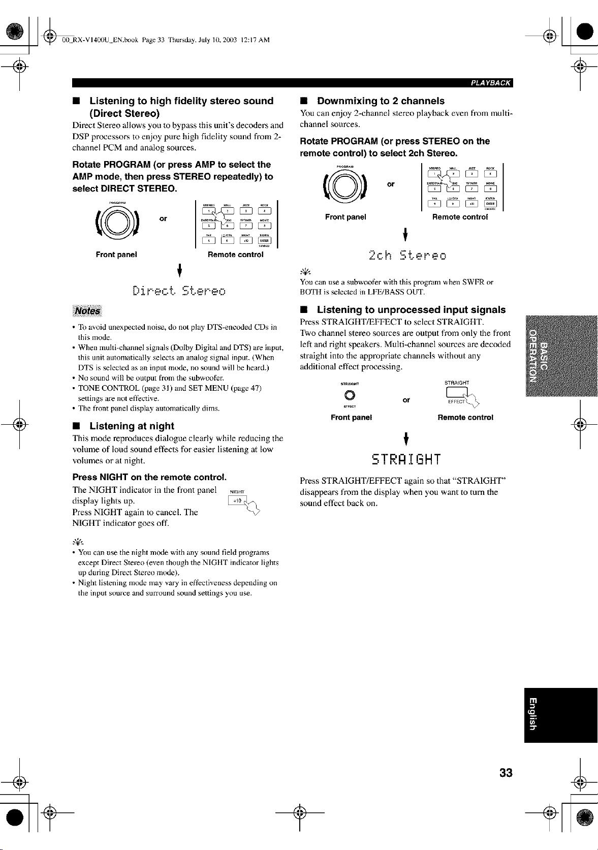
_ @0(t RX-VI40(IU EN.book Page 33 Thursday, July 10, 20(13
12:17 AM
• Listening to high fidelity stereo sound
(Direct Stereo)
Direct Slereo allows you 1o bypass this unit's decoders and
DSP processoi_s to enjoy pure high fidelity sound from 2-
channel PCM and analog sources.
Rotate PROGRAM (or press AMP to select the
AMP mode, then press STEREO repeatedly) to
select DIRECT STEREO.
O
Front panel
or
t
Remote control
F,, - .. = = Z _Z .....
L"t r "_.fL_ L • Z.'L'_fF'_fLJ
• Downmixing to 2 channels
You can enjoy 2=channelstereo playbackeven from multi-
channel sources.
Rotate PROGRAM (or press STEREO on the
remote control) to select 2ch Stereo.
Front panel Remote control
,-=_ °
Z.L-h '-± .....
You can use a subwoof_r with this program when SWFR or
BOTH is selected in LFE/BASS OUT.
+
• To avoid unexpected noise, do not play DTS-encoded CDs in
this mode.
• When multi-channel signals _Dolby Digital and DTS) are input,
this unit automatically selects an analog signal input. (When
DTS is selected as an input mode, no sound will be heard.)
• No sound will be output fi'om the subwoofEr.
• TONE CONTROL (page 31 ) and SET MENU (page 47)
settings are not et]ective.
• The front panel display automatically dims.
• Listening at night
This mode reproduces dialogue clearly while reducing the
volume of loud sound effects for easier listening at low
volumes or at night.
Press NIGHT on the remote control.
The NIGHT indicator in Ihe front panel NEGro
display lights up.
Press NIGHT again m cancel. The
NIGHT indicator goes off.
• Listening to unprocessed input signals
Press STRAIGHT/EFFECT 1o select STRAIGHT.
Two channel stereo sources are output from only _he front
left and right speakei_s. Multi-channel sources are decoded
straight inlo Ihe appropriate channels without any
additional effect processing.
_RA_H_ _TF_A_GHT
O or
Front panel Remote control
t
S'!"RA!
Press STRAIGHT/EFFECT again so that "STRAIGHT"
disappears from the display when you want to turn the
sound effect back on.
.,+,..
• You can use the night mode with any sound field programs
except Direct Stereo (even though the NIGHT indicator lights
up during Direct Stereo mode).
• Night listening mode m_y vary in effectiveness depending on
the input source and surround sound settings you use.
+
33

_ _00N RX-VI40(IU EN.book Page 34 Thursday, July 10, 20(13
12:17 AM
• Virtual CINEMA DSP
Virtual CINEMA DSP allows you to enjoy the CINEMA
DSP programs without surround speakers. It creates
virtual speakers 1o reproduce the nalural sound field.
If you do no1 connect surround speakers, Virtual CINEMA
DSP activates automatically whenever you select a
CINEMA DSP sound field program.
This unit comes with a variety of input jacks. Do the
following to select the type of input signals you want to
use.
1 Select the input source.
Virtual C1NEMA DSP will not activate, even when SURR L/R
SP is set to "NONE" (see page 49) in the following cases:
-- When MULTI CH INPUT is selected as the input source.
- When headphones are connected.
O
Front panel
or
Remote control
+
2
Press INPUT MODE to select an input mode.
In most cases, use AUTO.
Front panel
C)
Remote control
t
=_z_l..._
E**,IIE** , =-=tl"i"£"_=-=t"i"--
Input mode
RUTO Automalieally selects input signals in
the following order:
1) Digital signals*
2) Analog signals
DTS Selects only digital signals encoded in
DTS. If no DTS signals m'e input, no
sound is output.
ANALOG Selects only analog signals. If no
analog signals are input, no sound is
oulput.
* If this unit detects a Dolby Digital or DTS signal, the
decoder automatically switches to the appropriate sound
field program.
You can adjust the defauh input mode this unit selects when the
power is turned on (see page 54).
+
34
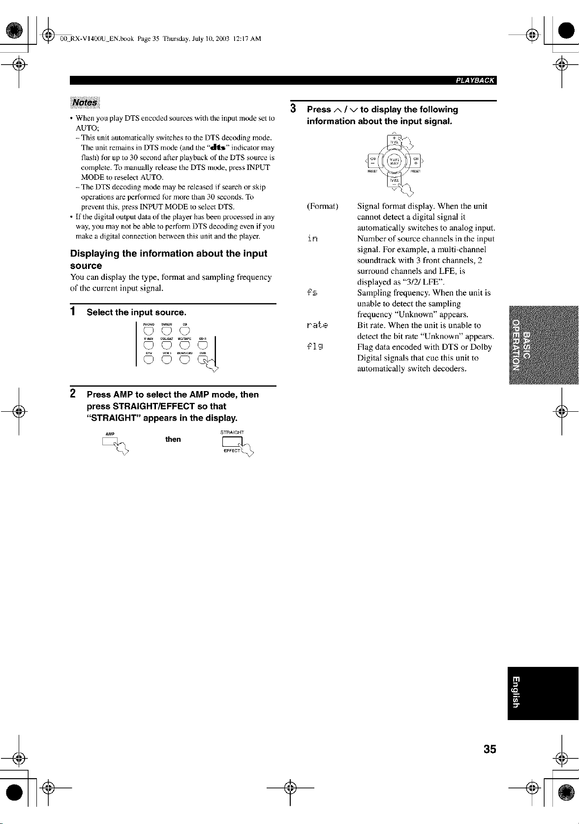
_ _0{t RX-VI400U EN.book Page 35
Thursday, July 10,2003 12:17 AM
+
• When you play DTS encoded sources with the input mode set to
AUTO;
--This unit automatically switches to the DTS decoding mode.
The unit remains in DTS mode (and the "_" indicator may
flash) tot up to 30 second after playback of the DTS source is
complete. To manually release the DTS mode, press INPUT
MODE m reselect AUTO.
-- The DTS decoding mode may be released if search or skip
operations are performed lk_rmore than 30 seconds. To
prevent this, press INPUT MODE to select DTS.
• If the digital output data of the player has been processed in any
way, you may not be able to perlk_rm DTS decoding even if you
make a digital connection between this unit and the player.
Displaying the information about the input
source
Youcan display the type, formal and sampling frequency
of thecurrant input signal.
1
Select the input source.
2
Press AMP to select the AMP mode, then
press STRAIGHT/EFFECT so that
"STRAIGHT" appears in the display.
A_p STRAIGHT
then
3 Press A / v to display the following
information about the input signal.
r.at.e
_'l'a
Signal formal display. When the unit
cannol detect a digital signal it
aulomafically switehes to analog input.
Number of source channels in the input
signal. For example, a multi-channel
sounOrack with 3 front channels, 2
surround channels and LFE, is
displayed as "3!2/LFE".
Sampling frequency. When the unit is
unable 1o detect the sampling
frequency "Unknown" appears.
Bit rate. When the unit is unable to
detect the bit rate "Unknown" appears.
Flag data encoded with DTS or Dolby
Digital signals that cue this unit to
automatically switeh decoders.
+
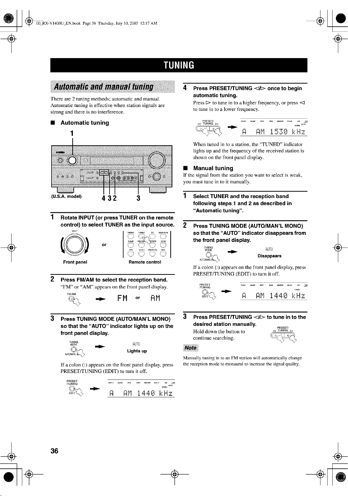
_ @00 RX-VI400U EN.book Page 36 Thursday, July lU, 20(13
12:17 AM
+
There are 2 tuning methods; automatic and manual.
Automatic tuning is effective when station signals are
strong and there is no interference.
• Automatic tuning
(U.S.A. model) 4 3 2 3
1
2
3
Rotate INPUT (or press TUNER on the remote
control) to select TUNER as the input source.
o,
Frontpanel Remotecontrol
Press FM/AM to select the reception band.
"FM" or "AM" appem's on the front panel display.
FM/AM
<_ -_ FM or FIN
Press TUNING MODE (AUTO/MAN'L MONO)
so that the "AUTO" indicator lights up on the
front panel display.
_J_NG
Lights up
If a colon C) appears on the front panel display, press
PRESETFFUNING (EDIT) to turn it oft'.
PRESET
frUNENG
R Rt'11440 kHz
4
Press PRESET/TUNING <_/I> once to begin
automatic tuning.
Press 1> to tune in to a higher frequency, or press <3
to tune in to a lower frequency.
PRESET/ _ c_ _v _ _A_ co_ cD Tu_
R Rt'1 1=",_,,:,0 k Hz
When tuned in to a station, the "TUNED" indicator
lighls up and the frequency of the received station is
shown on the front panel display.
• Manual tuning
If lhe signal from the station you want to select is weak,
you must tune in to it manually.
1 Select TUNER and the reception band
following steps 1 and 2 as described in
"Automatic tuning",
2
Press TUNING MODE (AUTO/MAN'L MONO)
so that the "AUTO" indicator disappears from
the front panel display,
TJNrNG
MODE RL_O
Disappears
If a colon C ) appears on the front panel display, press
PRESET/TUNING (EDIT) to turn it off.
PRESET _ c_ D_ _D _ c_ cD _
FOJNING
R Rt'11440 kHz
3
Press PRESET/TUNING <_h> to tune in to the
desired station manually.
PRESET/
Hold down the button to < TUNING_.
continue searching.
Manually tuning in to an FM station will automatically change
the reception mode to monaural to increase the signal quality.
+
36
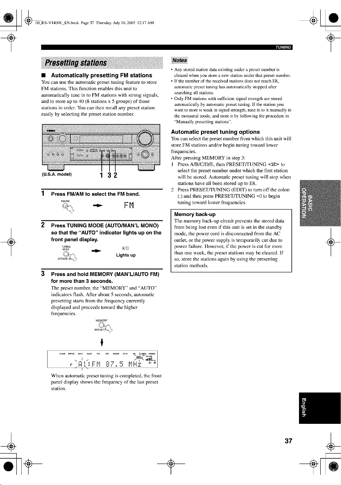
_ @0(t RX-VI40(IU EN.book Page 37 Thursday, July 10, 20(13
12:17 AM
+
• Automatically presetting FM stations
You can use the automatic preset tuning feature Io store
FM stations. This function enables this unit to
automatically tune in Io FM stations with strong signals,
and to slore up to 40 (8 stations x 5 groups) of those
stations in order. You can then recall any preset station
easily by selecting the preset station number.
(U.S.A.modeU 1 3 2
1
2
Press FM/AM to select the FM band.
FM/AM i.. M
_ I" I'1
Press TUNING MODE (AUTO/MAN'L MONO)
so that the "AUTO" indicator lights up on the
front panel display.
Lights up
3
Press and hold MEMORY (MAN'L/AUTO FM)
for more than 3 seconds.
The preset number, the "MEMORY" and "AUTO"
indicators flash. After about 5 seconds, automatic
presetting starts from the frequency currently
displayed and proceeds Ioward the higher
frequencies.
MEMORY
cD T_m _._o
_,_, .dilL.....
"+++'+'+++VP'I "'+" = P,+!- + +
+..N+,+,+• . . O l" + -J
j +
When automatic preset tuning is completed, the front
panel display shows the frequency of the last preset
station.
• Any stored station data existing under a preset number is
cleared when you store a new station under that preset number.
• If the number of the received stations does not reach ES,
automatic preset tuning has automatically stopped at_er
searching all stations.
• Only FM stations with sufficient signal strength are stored
automatically by automatic p_eset tuning. If the station you
want to store is weak in signal suength, tune in to it manually in
the monaural mode, and store it by tk_llowing the procedure in
"Manually presetting stations".
Automatic preset tuning options
You can select the preset number from which this unit will
slore FM stations and/or begin tuning toward lower
frequencies.
After pressing MEMORY in slep 3:
1 Press A]B/C/D/E, then PRESET_UNING <:1/1:>-to
select the preset number under which the first station
will be stored. Automatic preset tuning will stop when
stations have all been stored up to E8.
2 Press PRESET/TUNING (EDIT) to turn off the colon
(:) and then press PRESET/TUNING <:1to begin
tuning toward lower frequencies.
Memory back-up
The memory back-up circuit prevents the stored data
from being lost even if this unit is set in the standby
mode, the power cord is disconnecled from the AC
outlet, or the power supply is temporarily cut due 1o
power failure. However, if the power is cut for more
than one week, the preset stations may be cleared. If
so, store the stations again by using the presetting
station methods.
+
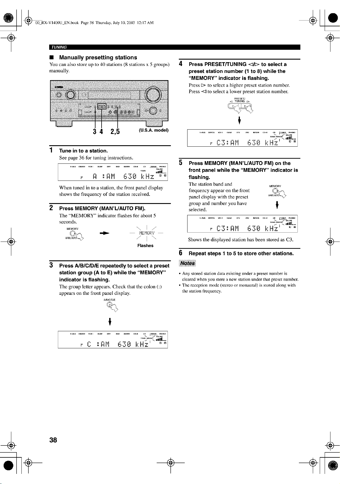
_ @00 RX-VI40(IU EN.book Page 38 Thursday, July 10, 20(13
II|q|'lli'[,
12:17 AM
• Manually presetting stations
You can also store up to 40 stations (8 stations x 5 groups)
manually.
4
Press PRESET/TUNING <_ to select a
preset station number (1 to 8) while the
"MEMORY" indicator is flashing.
Press 1:>to select a higher preset stalion number.
Press <_ to select a lower preset station number.
PRESET/
<l TUNING r_.
+
3 4 2,5 (U.S.A.model)
1 Tune intoa station.
See page 36 for tuning instructions.
,, H .l,lh [:"N" "....
• ....... -...a_ |
When tuned in to a stalion, the front panel display
shows the frequency of the station received.
2 Press MEMORY (MAN'L/AUTO FM).
The "MEMORY" indicator flashes for about 5
seconds.
Flashes
3
Press A/B/C/DiE repeatedly to select a preset
station group (A to E) while the "MEMORY"
indicator is flashing.
The group letter appears. Check that Ihe colon (:)
appeaiLs on the front panel display.
Ah3tC/D_E
%
- _ I " ,,1111111.....
t
5
Press MEMORY (MAN'L/AUTO FM) on the
front panel while the "MEMORY" indicator is
flashing.
The station band and _,_E_,tORY
frequency appear on the front
panel display with the preset
group and number you have
selected.
,[
/
........ IlL-
" "'= "'_'_"""_ " '" N_ I """_
Shows the displayed station has been stored as C3.
6 Repeat steps 1 to 5 to store other stations.
• Any stored station data existing under a preset number is
cleared when you store a new station under that preset number.
• The reception mode (stere() or monaum!) is stored along with
the station frequency.
+
38
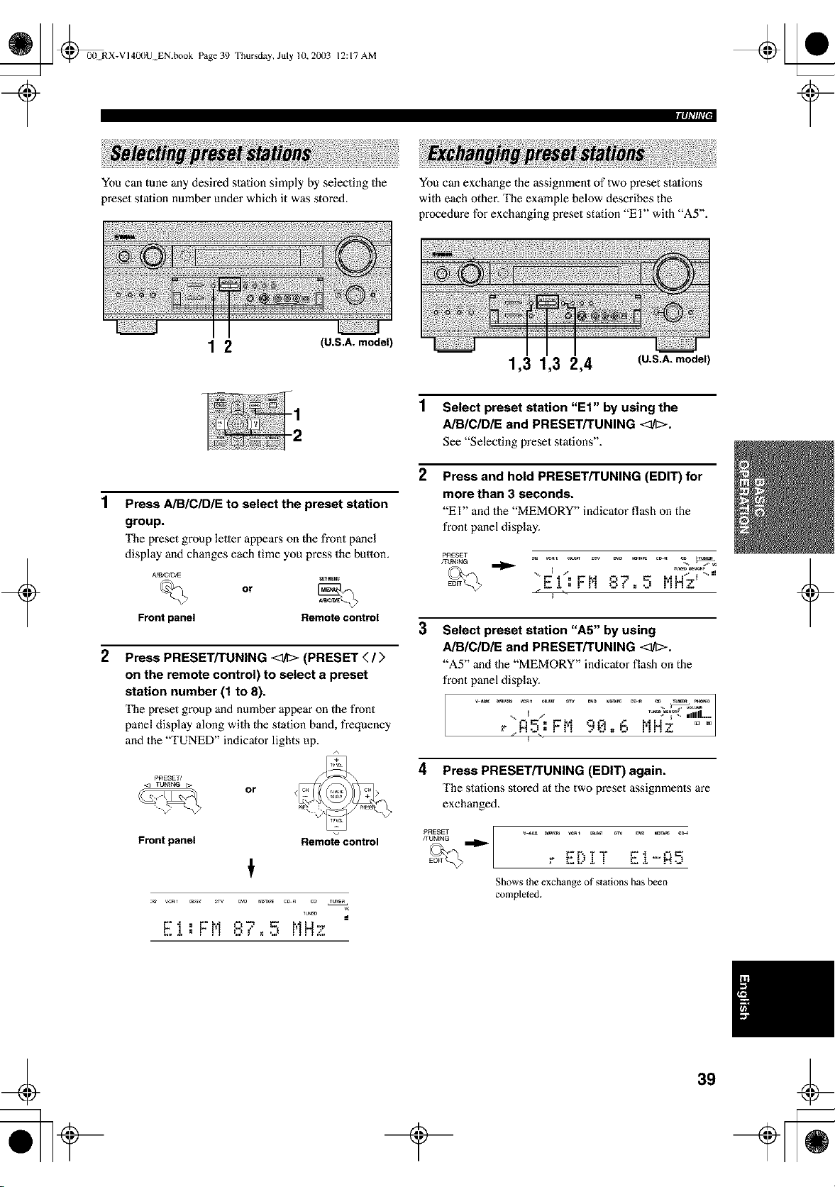
_ @00N RX-VI40(IU EN.book Page 39 Thursday, July 10, 20(13
12:17 AM
You can tune any desired station simply by selecting the
preset station number under which it was stored.
1 2 (U.S.A. model)
You can exchange the assignment of two preset stations
with each other. The example below describes the
procedure for exchanging preset station "El" with "A5".
1,3 1,3 2,4 (U.S.A. model)
1 Select preset station "Et" by using the
AIBICIDIE and PRESET/TUNING <at;>.
See "Selecting preset stations".
2 Press and hold PRESET/TUNING (EDIT) for
more than 3 seconds.
"El" and the "MEMORY" indicator flash on the
front panel display.
1
Press AIBICIDIE to select the preset station
group.
The preset group letler appears on the front panel
display and changes each time you press the button.
or
Front panel Remote control
2
Press PRESET/TUNING _ (PRESET </>
on the remote control) to select a preset
station number (1 to 8).
The preset group and number appear on the front
panel display along with the station band, frequency
and the "TUNED" indicator lights up.
PRESET/
Front panel
or
Remote control
TUNED
EI:FN ,:,v 5 NHz
I.tl _ II _.t
II
_-b _.
3
Select preset station "A5" by using
AIBICIDIE and PRESET/TUNING <ltl>.
"A5" and 1he "MEMORY" indicator flash on the
front panel display.
mdm
i,IIIII .....
4 Press PRESET/TUNING (EDIT) again.
The stations stored at the two preset assignments are
exchanged.
PRESET
FUN_NG
Shows the exchange of stations has been
completed.
+
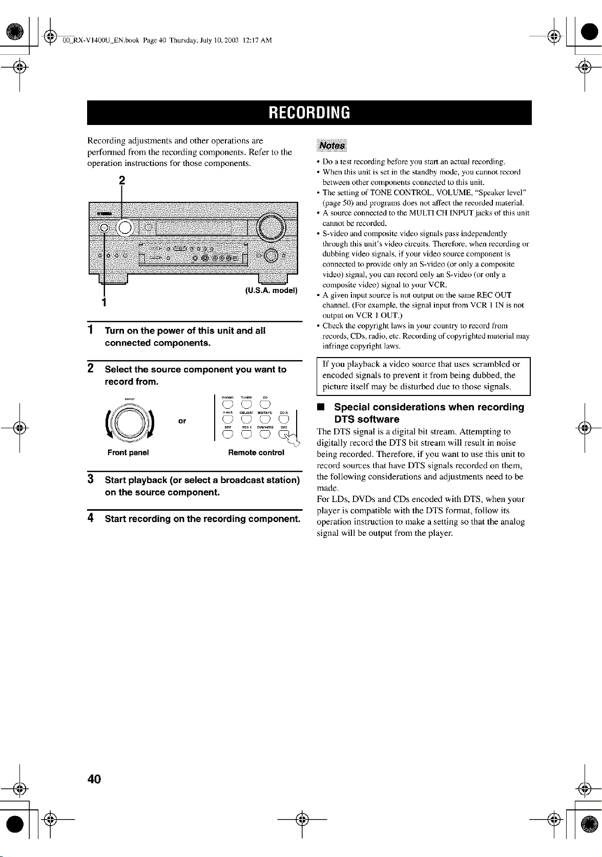
_ @0(t RX-VI40(IU EN.book Page 4(I Thursday, July 10, 20(13
12:17 AM
+
Recording adjustments and olher operations are
performed from the recording components. Refer to the
operalion instructions for those components.
2
(U.S.A. model
1
1 Turn on the power of this unit and all
connected components.
2 Select the source component you want to
record from.
O
Front panel
or
Remote control
3 Start playback (or select a broadcast station)
on the source component.
4 Start recording on the recording component.
• Do a test rec_rding be_k_reyou start an actual recording.
• When this unit is set in the standby mode, you cannot record
between other components connected to this unit.
• The setting of TONE CONTROL, VOLUME, "Speaker level"
(page 50) and programs does not affect the recorded material.
• A source connected to the MULTI CH INPUT jacks of this unit
cannot be recorded.
• S-video and composite video signals pass independently
through this unit's video circuits, Therefk_re, when recording or
dubbing video signals, if your video source component is
connected _o provide only an S-video (or only a composite
video) signal, you can record only an S-video (or only a
composite video) signal to your VCR.
• A given input soarce is not output on the same REC OUT
channel. (For example, the signal input from VCR 1 IN is not
output on VCR 1 OUT.)
• Check the copyright laws in your country to record flora
records, CDs, radio, etc. Recording of copyrighted material may
inf¥inge copyright laws.
If you playback a video source that uses scrambled or
encoded signals to prevent it from being dubbed, the
picture itself may be disturbed due to those signals.
• Special considerations when recording
DTS software
The DTS signal is a digital bit slream_ Attempting to
digitally record the DTS bit stream will result in noise
being recorded. Therefore, if you want 1o use this unit to
record sources that have DTS signals recorded on them,
the following considerations and adjustments need 1o be
made.
For LDs, DVDs and CDs encoded with DTS, when your
player is compatible with the DTS formal, follow its
operation instruction to make a setting so that the analog
signal will be oulput from the player.
+
40
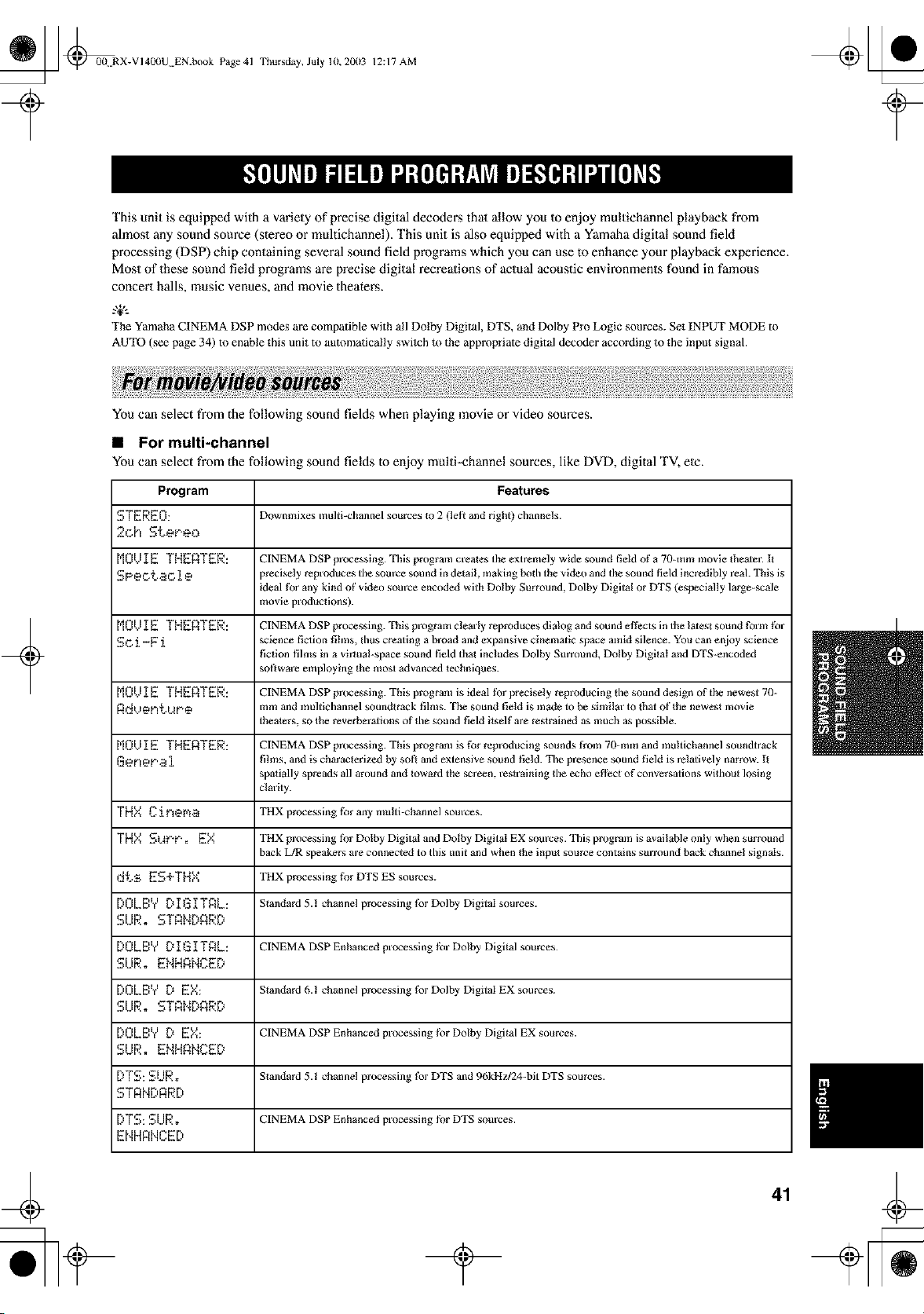
_ _0(! RX-VI400U EN.book Page 41
Thursday, July 10,2003 12:17 AM
This unit is equipped with a variety of precise digital decodens that allow you Io enjoy multichannel playback from
almost any sound source (stereo or mukichannel). This unit is also equipped with a Yamaha digital sound field
processing (DSP) chip containing several sound field programs which you can use to enhance your playback experience.
Most of these sound field programs are precise digital recreations of actual acoustic environments found in famous
concert halls, music venues, and movie theaters.
g+,.
The Yamaha CINEMA DSP modes are compatible with all Dolby Digital, DTS, and Dolby Pro Logic sources. Set INPUT MODE to
AUTO (see page 34) to enable this uniI to automatically switch it) the appropiiate digital decoder according to the input signal.
+
You can select from the following sound fields when playing movie or video sources.
• For multi-channel
You can select from the following sound fields to enjoy multi-channel sources, like DVD, digital "I'V,etc.
Program Features
STEREO: Downmixes multi-channel sources Io 2 (lefi and right) channels.
2oh Steeeo
MOl)IETHEATER: CINEMADSPpl_ocessing.Thisprogramcrealestheextremelywidesoundfieldofa 70-rammoviethemer.It
SPeotao i e precisely reproduces the som'ce sound in detail, making both the video and the sound field incredibly reak This is
ideal fbr any kind of video source encoded with Dolby Surround, Dolby Digital or DTS (especially large-scale
movie productions).
M01JIE THEATER: CINEMA DSP processing. This prograin clearly reproduces dialog and sound effects in the latesl sound form for
Sc.i-F i science fiction fihns, thus creating a broad and expansive cinematic space amid silence. You can enjoy science
fiction films in a virtual-space soaod field thai includes Dolby Surround, Dolby Digital and DTS-encoded
sofiware employing the most advanced lechalques.
M01..II E THEATER: CINEMA DSP processing. This program is ideal tbr precisely reproducing the sound design of the newest 70-
ANVOFI_..MF, O mm and multichannel soundtrack films. The sound field is made to be similar to that of the newest movie
theaters, so the reverberations of lhe sotmd field itself are restrained as much as possible.
M01...II E THERTER: CINEMA DSP processing. This program is for reproducing sounds from 70-rain and mtdtichannel soundtrack
Gener,ai films, and is characterized hy soft and extensive sound field. The presence sound field is relatively narrow. II
spatially spreads all around and Ioward the screen, reslralning the echo eflhct of conversations without losing
clarity.
THY,CireNa THXprocessingforanymufii-channelsources.
THY,SMPP. EY, THX processing fbr Dolby Digital and Dotby Digital EX soumes. This program is available only when surround
back L/R speakers are connected to this unit and when the inpul source contains surround back channel signals.
,:ItsES+THX THXprocessingfor DTSESsources.
[:'OLB'v' D I G I TAL: Slandard 5.1 channel processing for Dolby Digital sources.
SIJR. STANDARD
[:,OLB'v' D I G I TAL: CINEMA DSP Enhanced processing for Dolby Digital sources.
SUR. ENHANCE[)
[:,0L8","D EY,: Slandard6.1channelprocessingfbrDolbyDigitalEXsources.
SIJR. STANDARD
[:,0LBVD EY,: CINEMADSPEnhancedprocessingforDolbyDigitalEXsources.
SUR. ENHANCE[)
[:,TS: SUR. Slandard 5.1 channel processing fbr DTS and 96kHzJ24-bit DTS sources.
E,T R N [:'R R [:'
[:,TS:SURo CINEMA DSP Enhanced processing fi)r DTS som'ces.
ENHFtNCE[:'
41
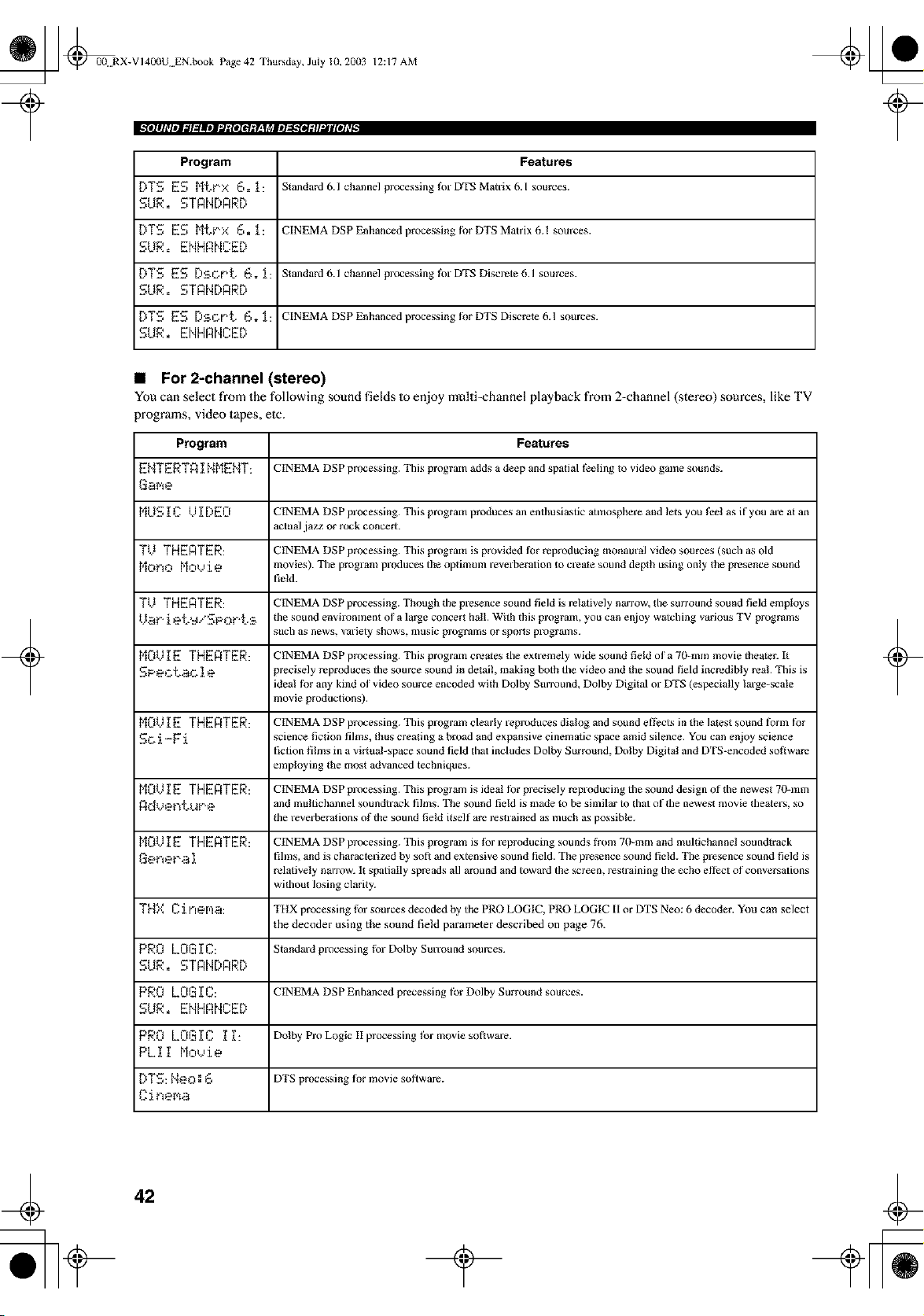
_ @00 RX-VI400U EN.book Page 42 Thursday, July 10, 20(13
12:17 AM
Program Features
DTS ES Mtt'X 6.1: Standard 6.l channal processing for DTS Matrix 6.1sources.
SLtR. STANDARD
DTS ES MtPx 6. _: CINEMA DSP Enhanced processing fi)rDTSMatrixh.1 sources.
SUR. ENHRNCED
DTS ES [):BCDt2, 6. l: Standard 6.1 channel processing for DTS Discrete 6.1 sources.
SUR. STANDARD
DTS ES [):BoPt, 6. _[: CINEMA DSP Enhanced processing fi)r DTS Discrete 6.1 sources.
SUR. ENHRNCED
• For 2-channel (stereo)
You can select from the following sound fields Io enjoy multi=channel playback from 2-channel (stereo) sources, like TV
programs, video tapes, elc.
Program Features
EblTERTAI t,,IMEblT: CINEMA DSP processing. This program adds a deep and spatial feeling Io video game sounds.
Game
MUG ]_C /.I I [)EO CINEMA DSP processing. This program produces an enthusiastic atmosphere and lets you feel as if you are at an
actual jazz or rock concert.
TV THERTER: CINEMA DSP processing. This program is provided fi_r reproducing monaural video sources (such as old
Mono Mo,...,ie movies). The program produces the optimuln reverberation to create sound depth using only the presence sound
field.
TIJ THEATER: CINEMA DSP processing. Though the presence sound fiald is ralatively narrow, the surround souod fiald emptoys
kL_t" i et'_*,"SPOP_.:B the sound envil'onxnent of a large concert hall. With this program, you can enjoy winching variotls TV programs
such as news, variety shows, mtlsic progralns or sports progralns.
M0VI g THEnTER: CINEMA DSP processing. This program creates the extremely wide sound field of a 70-mm movie theater. It
SPeC.t,_O ie precisely reproduces the source sound in detail, making both the video and the sotmd field incredibly real. This is
ideal fi)r any kind of video source encoded with Dolby Stlrround, Dolby Digital or DTS (especially large-scale
movie productions).
M0VI E THERTER: CINEMA DSP processing. This program clearly reproduces dialog and sound effects in the latest sound fbrin tbr
SO. i -F i science fiction films, thus creating a broad and expansive cinematic space amid silence. You can enjoy science
fiction films in a virtual-space sound field that includes Dolby Surround, Dolby Digital and DTS-encoded soflware
employing the most advanced techniques.
M0VI E THERTER: CINEMA DSP processing. This program is ideal tbr precisely reproducing the sound design of the newest 70-inm
Adv@nthlr@ and mu fiichannel soundtrack films. The sound field is made to be similar to that of the newest movie theaters, so
the reverberafions of the sound field itself are reslralned as much as possible.
M0VI E THERTER: CINEMA DSP processing. This program is for reproducing sounds from 70-mm and multichannel soundtrack
Get'tep,_ i fihns, and is characterized by sofi and extensive sound field. The presence sound field. The presence sound field is
relatively narrow. It spatially spreads all amtmd and toward the screen, restraining the echo effect of conversations
without losing clarity.
THX Cinema: TI"IXprocessingforsourcesdecodedbythePROLOGIC,PROLOGICIIorDTSNeD:6 decoder.Youcanselect
the decoder using the sound field parameter described on page 76.
PRO LOGI C: Standard processing for Dolby Sulvound sources.
SUR. STANDARD
PRO LOGIC: CINEMADSP Enhancedprecessingtbr Dolby Surroundsources.
SUR. ENHRNCED
PRO LOGIC If: DolbyProLogicIIprocessingt_rmoviesofiware.
PLII Moh,ie
DTS: t,,leo: 6 DTS processing fi_r movie sol,ware.
Ciner¢_a
+ +
42
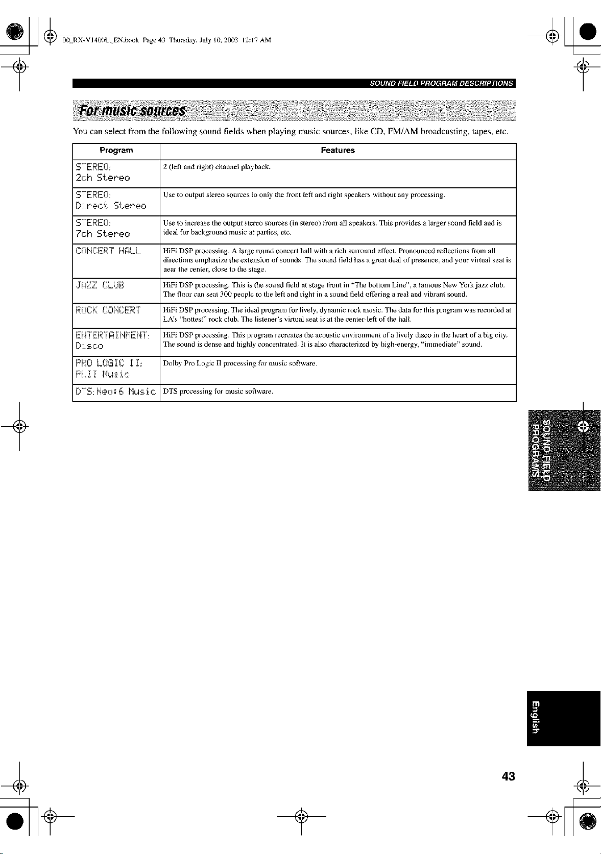
_ @0(t RX-VI4(X)U EN.book Page 43 Thursday, July 10, 20113 12:17 AM
t#llh_lmJ_lg_llml_gloi_gF._Tl_lml_golgli.Jil[Oh_ I
You can select from the following sound fields when playing music sources, like CD, FM/AM broadcasting, tapes, elc.
Program Features
STEREO: 2 (lef_ and right) channel playback.
2oh Stereo
STEREO: Use to output stereo som'ces to only the front left and right speakers without any processing.
[:'ir'eot Ster.eo
STEREO: Use to increase tile output stereo som'ces (in stereo) from all speakers. Ellis provides a larger sound field and is
7oh StePeo ideal for background mtlsic at palales, elc.
CONCERT HALL HiFi DSP processing. A large round concert hall with a rich sun'ound effect. Pronounced reflections from all
directions emphasize the extension of sounds. The sound field has a great deal of presence, and your vir_uat sezt is
near the cen_er, clo_ to the stzge.
.JAZZ CLUE: HiFiDSPprocessing.Ellisis thesotlndfieldatstagefrontin'"thebottoinLine',a thmousNewYorkjazzclub.
The floor can seat 300 people to the left and right in a sound field ofl?ring a real and vibran_ sound.
ROCK CONCERT HiFi DSP processing. The ideal program tbr lively, dynamic rock music. The data tbr this program was recorded at
LA's "hottest" rock club. The listener's virtual seat is at the center-lefl of the hal!.
ENTERTR I NMENT: HiFi DSP processing. This program recreates the acotlstic environment of a lively disco in the heart of a big city.
[) i SOO The sound is dense and highly concenlraled. I_ is also characterii_ed by high-energy, "immediate" sound.
PRO LOGIC II: DolbyProLogicllprocessingformtlsicsoflware.
PLII Mu_.ic
[:'TS: Neo: 6 Mus i c DTS processingfor musicso|_ware.
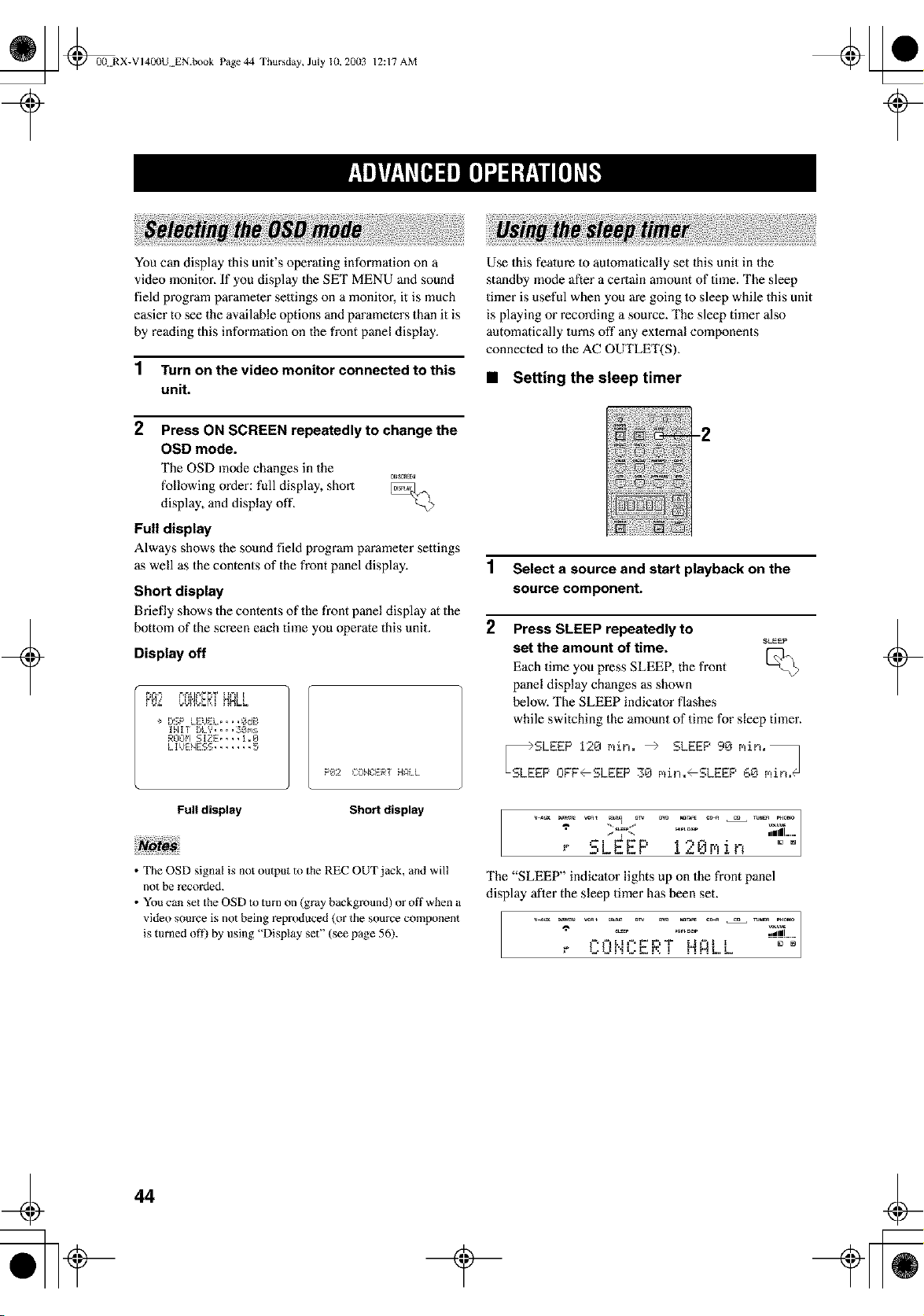
_ @00 RX-VI400U EN.book Page 44 Thursday, July 10, 20(13
12:17 AM
+
You can display this unit's operaqng informaqon on a
video monitor. If you display the SET MENU and sound
field program parameter settings on a monitor, it is much
easier to see the available options and parameters than it is
by reading this informaqon on the front panel display.
1 Turn on the video monitor connected to this
unit.
2
following order: full display, short
display, and display off.
Full display
Press ON SCREEN repeatedly to change the
OSD mode.
The OSD mode changes in the
C_SC_Eal
Always shows the sound field program pm'ameter settings
as well as the contents of the front panel display.
Short display
Briefly shows the contents of the front panel display at the
bottom of the screen each time you operate this unit.
Display off
÷ DSP LEUEL....OdB
INIT DLY....3Oms
ROOM SIZE.... 1.0
LIUENESS ....... 5
P8:2 EQNC:ERTHAi_L
Use this feature 1o aulomatically set 1his unit in the
standby mode after a certain amount of time. The sleep
timer is useful when you are going 1o sleep while this unit
is playing or recording a source. The sleep timer also
automatically turns off any exlernal components
connected to the AC OUTLET(S).
• Setting the sleep timer
-2
1 Select a source and start playback on the
source component.
2 Press SLEEP repeatedly to
SLEEP
set the amount of time.
Each time you press SLEEP, the front k__
panel display changes as shown
below. The SLEEP indicator flashes
while switching the amount of time for sleep timer.
S_LESLEEP 120 rain. _ SLEEP 90 min=_
EP OFF--SLEEP 30 min._SLEEP 60 min/@
+
Full display Short display
• The OSD signal is not output m the REC OUT jack, and will
not be recorded.
• You can set the OSD to ram on (gray background) or off when a
video source is not being repr(xluced (or the source component
is turned of_) by using "Dispby set" (see page 56).
7
r _U_
/
=Ill .....
The "SLEEP" indicator lights up on the front panel
display after the sleep timer has been set.
ULh" ! HALL
44
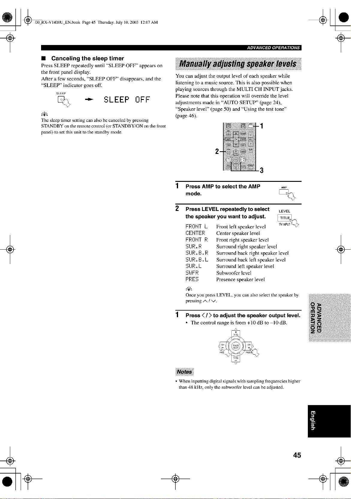
_ @00 RX-VI40llU EN.book Page 45 Thursday, July 10,20(13
?
12:17 AM
,rm]rl'_T&_[_mlOl¢l,_.*¥±Ifl[el_Tl
• Canceling the sleep timer
Press SLEEP repeatedly until "SLEEP OFF" appears on
the front panel display.
After a few seconds, "SLEEP OFF" disappears, and the
"SLEEP" indicator goes off.
SLEEP
SLEEP OFF"
The sleep timer setting can also be canceled by pressing
STANDBY on the remote control (or STANDBY/ON on the front
You can adjust the output level of each speaker while
lislening to a music source. This is also possible when
playing sources through the MULTI CH INPUT jacks.
Please note thai this operation will override the level
adjustments made in "AUTO SETUP" (page 24),
"Speaker level" (page 50) and "Using the lest lone"
(page 46).
-1
panel) to set this unit to the standby mode.
+
3
1 Press AMP to select the AMP
mode,
2 Press LEVEL repeatedly to select LEVEL
the speaker you want to adjust.
FRONTL
CENTER
FRONTR
SUR,R
SUR,B,R
SUR,B.L
SURoL
SWFR
PRES
Front lefl speaker level
Center speaker level
Front right speaker level
Surround right speaker level
Surround back right speaker level
Surround back lefl speaker level
Surround left speaker level
Subwoofer level
Presence speaker level
Once you press LEVEL, you can also select the speaker by
pressing/x / v.
1 Press < / > to adjust the speaker output level.
• The control range is from +10dB to-10dB.
+
• When inputting digital signals with sampling fi'equencies higher
than 48 kHz, only the subwoof_r level can be adjusted.
45
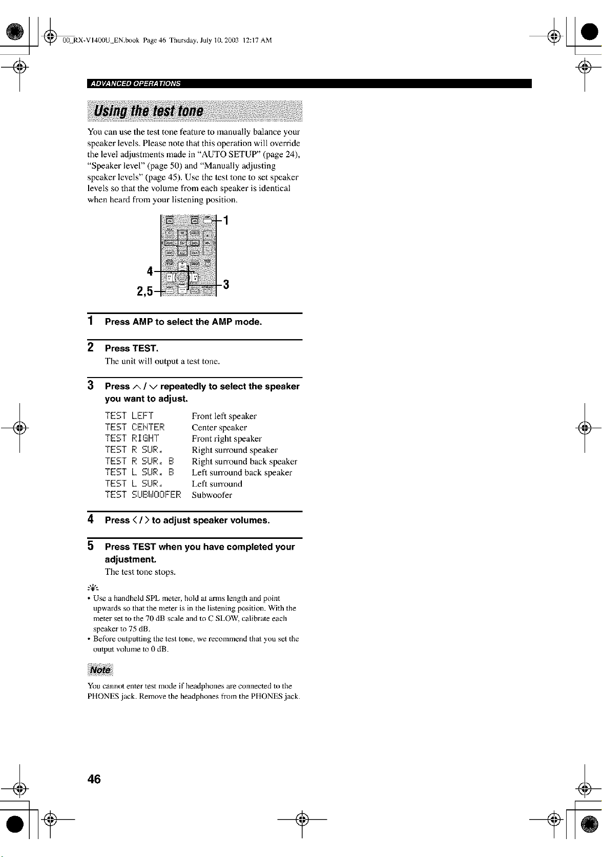
_ @0(t RX-VI400U EN.book Page 46 Thursday, July 10, 20(13
12:17 AM
_ittlV,_|#lOl_ttloI_d_gF,_ll[oi#_
You can use the lest tone feature lo manually balance your
speaker levels, Please note that this operation will override
the level adjustments made in "AUTO SETUP" (page 24),
"Speaker level" (page 50) and "Manually adjusting
speaker levels" (page 45). Use the lest lone lo set speaker
levels so that the volume from each speaker is identical
when heard from your lislening position.
+
1 Press AMP to select the AMP mode.
2 Press TEST.
The unit will output a test tone.
3
Press/x ! v repeatedly to select the speaker
you want to adjust.
TEST LEFT
TEST CENTER
TEST RIGHT
TEST R SUR.
TEST R SUR. B
TEST L SUR. B
TEST L SUR.
TEST SUBWOOFER
Front lefl speaker
Center speaker
Front right speaker
Right surround speaker
Right surround back speaker
Lefl sun'ound back speaker
Eefl surround
Subwoofer
4 Press < / > to adjust speaker volumes.
5 Press TEST when you have completed your
adjustment.
The lest |one slops.
.%,..
• Use a handheld SPL meter, hold at arms length and point
upwards so that the mete_ is in the listening position. With the
meter set to the 70 dB scale and to C SLOW, calibrate each
speaker to 75 dB.
• BefOre outpu_ting the test tone, we recommend that you set the
output volume to 0 dB.
+
You cannot enter test mode if headphones are connected to the
PHONES jack. Remove the headphones from the PHONES jack.
46
_ @00 RX-VI4OI)U EN.book Page 47 Thursday, July 10, 2003
12:17 AM
+
You can use the following parameters in the set menu to adjust a variety of system settings and customize the way this
unit operates. Change the initial settings (indicated in hold under each parameter) to reflect Ihe needs of your listening
environment.
• Auto Setup
Use to specify which speaker parameters auto setup will adjust, and 1o activate Ihe aulo setup procedure (see page 24).
• Manual Setup
Use to manually adjust speaker and system settings.
.,+,.
Most of the parameters described in the SOUND menu are set automatically when you run auto setup (see page 24). You can use the
SOUND menu m make further adjustments, but we recommend running auto setup first.
Basic menu
Use to quickly setup basic system parameters (see page 28).
Sound menu
Use to manually adjust any speaker setting or compensate for video signal processing delays when using LCD monilors
or projectors.
Item
SPEAKER SET
Features Page
Selects the output mode suitable for each speaker, lhe speakers for low-frequency signat output, 49
and the cross over ti'equency.
SP LEOEL Adjusts the output level of each speaker. 50
SP DISTANCE Adjusts the delay time of each speaker. 51
GRnPHIC EQ Adjusts the tonal quality of each speaker. 51
LPE LEOEL Adjusts the output level of the LFE channel for Dolby Digital or DTS signals. 51
0E'E'ENFt['II C RANGE Adjusts the dynamic range for Dolby Digital or DTS signals. 52
L01,,,I FRQ. TEST Malches the subwoofcr level with the level of lhe olher speakers. 52
HP TONE CTRL Adjuststhelonalbalanceoflheheadphones. 53
AUDIO SET Customizes overatl audio settings of this unit. 53
PRiSBc.h _ELECT Selects priority to either surround back or presence speakers when both sets of speakers are 53
connected to this unit.
Input menu
Use to reassign digital input/outputs, select the input mode, rename your inputs, or specify external input settings.
Item Features Page
IiO A_ ]_L_N ,_..ssignsjacks according to the component to be used. 54
I NPUT NODE Selects the initial input mode of _he sotlrce. 54
INPUT RENRME Changes the name of the inputs. 55
E_':',T. INPUT Sets the direction of the signals input into _he center, subwool_r and SmTOundchannels for lhe 55
source component connected to the MULTI CH INPUT jacks.
+
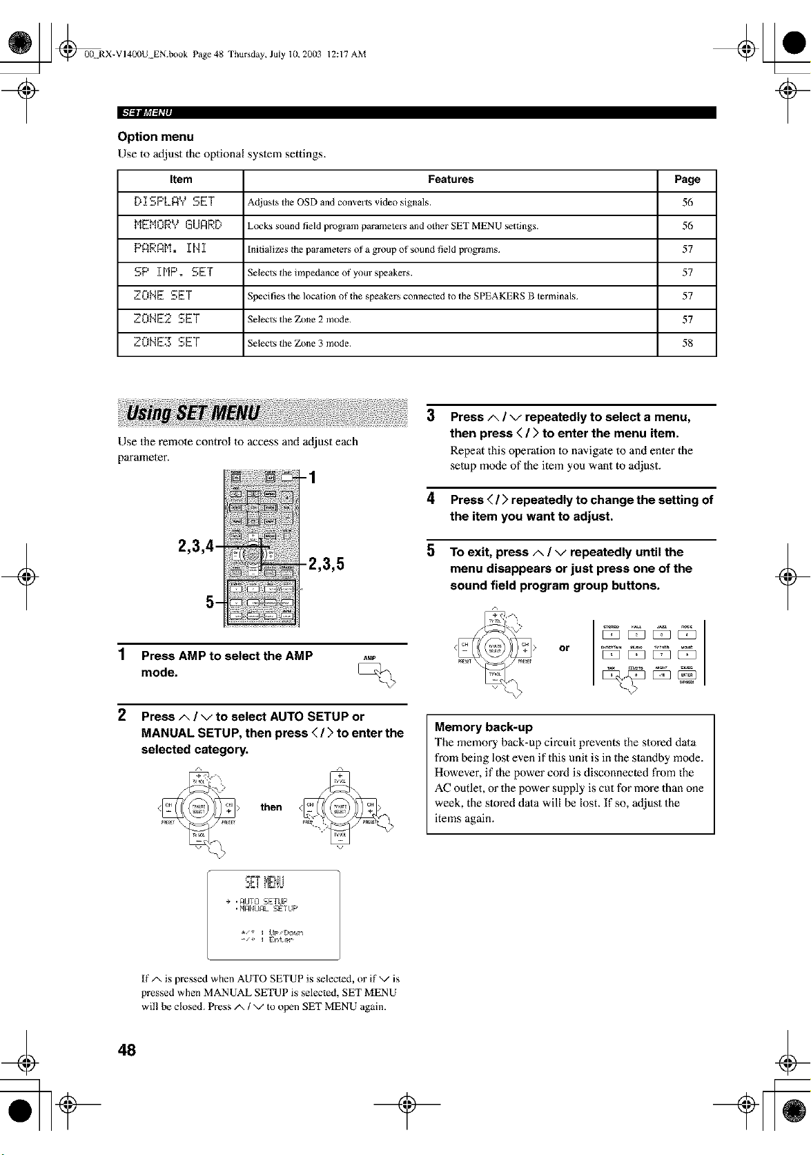
_ @00 RX-VI4OllU EN.book Page 48 Thursday, July 10, 2003
12:17 AM
€'/,_Jt '/I,_L
Option menu
Use to adjust the oplional syslem settings.
Item Features Page
D _[SPLI)Y SET Adjusts the OSD and converts video signals. 56
MEMORY GUARD Locks sound field program parameters and other SET MENU settings. 56
PAP.A[']. _[N I Initializes the parametersof a group of sound field programs. 57
SP _[MP. SET Selects tile impedance of your speakers. 57
ZONE SET Specifies the location of the speakers connected to the SPEAKERS B terxninals. 57
_'.ONE2 SET Selects the Zone 2 mode. 57
ZONE3 SET Selects the Zone 3 mode. 58
+
Use the remote control to access and adjust each
parameter.
-1
2,3,4-
5-
-2,3,5
1 Press AMP to select the AMP
mode.
2 Press A / v to select AUTO SETUP or
MANUAL SETUP, then press < / > to enter the
selected category.
then
3 Press A / v repeatedly to select a menu,
then press < / > to enter the menu item.
Repeat this operadon 1o navigate to and enler the
selup mode of Ihe item you want to adjust.
4 Press ( / > repeatedly to change the setting of
the item you want to adjust.
5 To exit, press A / v repeatedly until the
menu disappears or just press one of the
sound field program group buttons.
or
Memory back-up
The memory back-up circuit prevents the slored dala
from being lost even if this unit is in the standby mode.
However, if the power cord is disconnected from the
AC outlet, or the power supply is cut for more than one
week, the slored dala will be lost. If so, adjust the
items again.
+
5g! i E;i'!_J
e ,_UTG SETLIP
•FI_ItLI_L.SETUP
If/x is pressed when AUTO SETUP is selected, or if v is
pressed when MANUAL SETUP is selected, SET MENU
wil! be closed. Press/x / v to open SET MENU again.
48
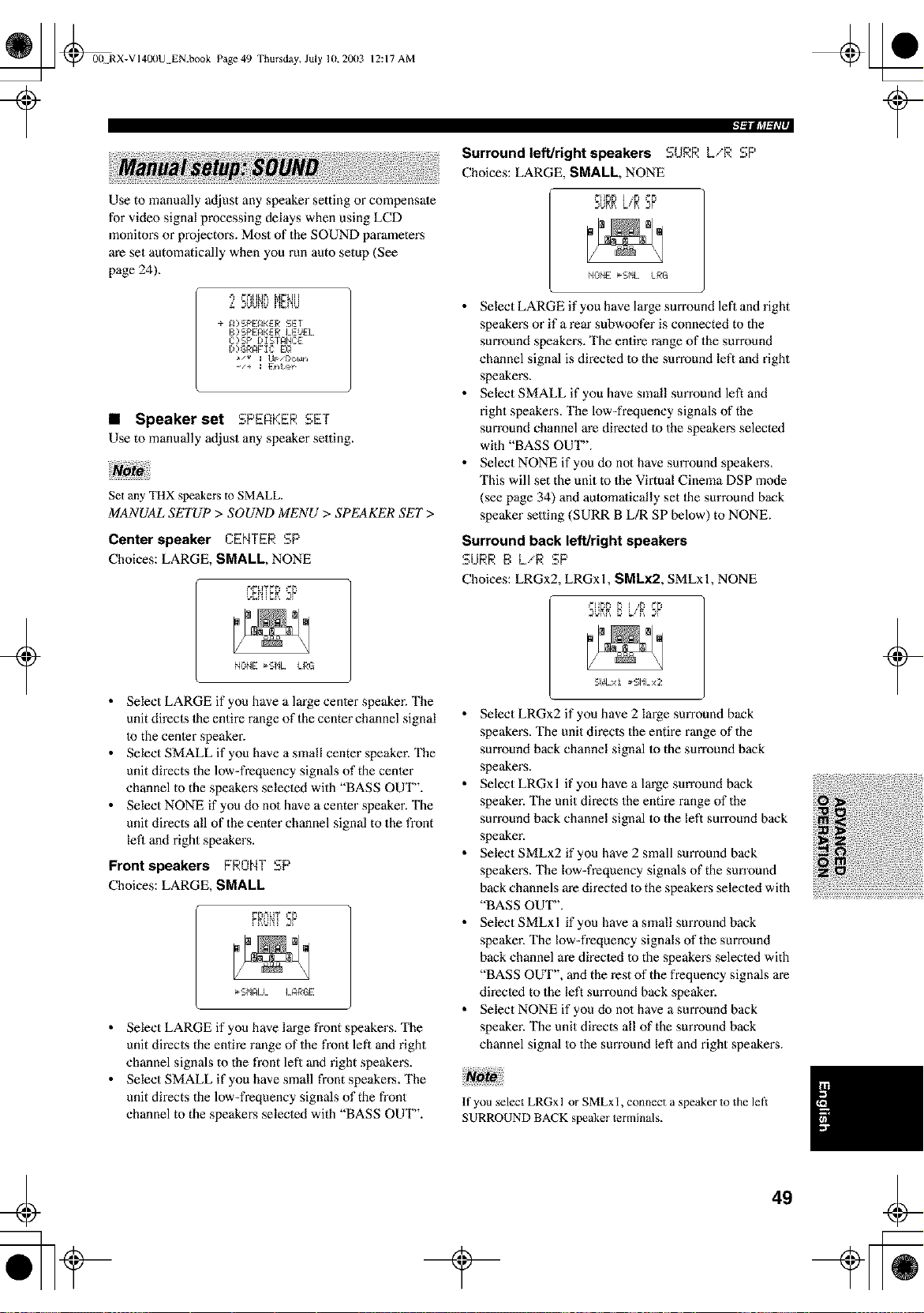
_ @00 RX-VI400U EN.book Page 49 Thursday, July 10,20(13
12:17 AM
Use to manually adjust any speaker setting or compensate
for video signal processing delays when using LCD
monitox:s or projectors. Most of the SOUND parameters
are set automatically when you run auto setup (See
page 24).
L 2UUF_L_MC_'!U
÷ _ SPEAKER SET
B SPEAKER LEUEL
C)SP DIS I_NCE:
I))GR_F Ig E:Q
• Speaker set SPERKER SET
Use to manually adjust any speaker setting.
+
Set any THX speakers to SMALL.
MANUAL SETUP > SOUND MENU > SPEAKER SET>
Center speaker CENTER SP
Choices: LARGE, SMALL, NONE
_.T_nSP
NUNE _I,L I.RG
• Select LARGE if you have a large center speaker. The
unit direcls the entire range of the center channel signal
Io the center speaker.
• Select SMALL if you have a small center speaker. The
unit directs the low-frequency signals of the center
channel to the speakers selected with "BASS OUT".
• Select NONE if you do no1 have a center speaker. The
unit directs all of the center channel signal to the front
left and fight speakers.
Front speakers FRONT SP
Choices: LARGE, SMALL
PNum SP
• Select LARGE if you have large front speakers. The
unit directs the entire range of the front left and right
channel signals to the front left and right speakers.
• Select SMALL if you have small front speakers. The
unit directs the low-frequency signals of the front
channel to the speakers selected with "BASS OUT".
'- l, SP
Surround left/right speakers :.._R L,"R
Choices: LARGE, SMALL, NONE
dKK SP
NUNE _I,L LRG
• Select LARGE ifyou have large surround left and right
speakers or if a rear subwoofer is connected to the
surround speakers. The entire range of the surround
channel signal is directed to the surround left and right
speakers.
• Select SMALL if you have small surround left and
right speakers, The low-frequency signals of the
surround channel are directed to the speakers selected
with "BASS OUT".
• Select NONE if you do not have surround speakers,
This will set the unit to the Virtual Cinema DSP m_xte
(see page 34) and automafically set Ihe surround back
speaker setting (SURR B L/R SP below) to NONE.
Surround back left/right speakers
SURR E:L/R SP
Choices: LRGx2, LRGx 1, SMLx2, SMLx 1, NONE
UKK SP
S_OI.xi _-SI%x2
• Select LRGx2 if you have 2 Imge surround back
speakers. The unit directs the entire range of the
surround back channel signal Io the sun'ound back
speakers.
• SelectLRGxl if you have a large sun'ound back
speaker. The unit directs the entire range of the
surround back channel signal to the left surround back
speaker.
• Select SMLx2 if you have 2 small surround back
speakers. The low-frequency signals of the sun'ound
back channels are directed to the speakers selected with
"BASS OUT".
• Select SMLxl if you have a small surround back
speaker. The low-frequency signals of the surround
back channel are directed to the speakers selected with
"BASS OUT", and the rest of the frequency signals are
directed to the left surround back speaker.
• Select NONE if you do nol have a surround back
speaker. The unit directs all of the surround back
channel signal to the sun'ound left and right speakers.
If you select LRGx l or SMLx I, connect a speaker to the left:
SURROUND BACK speaker terminals.
+
¢
49
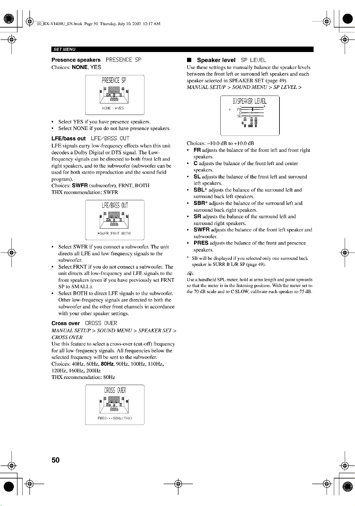
_ @00. RX-VI400U EN.book Page 50 Thursday, July 10, 2003
+
12:17 AM
r SP
Presence speakers PRE_,EN_.E
Choices: NONE, YES
F_F_F'_=F'L[_',F' _F_
HONE _YES
• Select YES if you have presence speakers.
• Select NONE if you do not have presence speakers.
LFE/bass out LFEiBRSS OUT
LFE signals carry low=frequency effects when this unit
decodes a Dolby Digital or DTS signal. The Low-
frequency signals can be directed to bolh front lefl and
right speakers, and to the subwoofer (subwoofer can be
used for both storeo reproduction and the sound field
program).
Choices: SWPR (subwoofer), FRNT, BOTH
THX recommendation: SWFR
_S£FR FRNT BOrN
• Select SWFR if you connect a subwoofer. The unit
directs all LFE and low=frequency signals to the
subwoofer.
• Select FRNT if you do no1 connect a subwoofer_ The
unit directs all low=frequency and LFE signals to the
front speakers (even if you have previously set FRNT
SP to SMALL).
• Select BOTH to direct LFE signals to the subwoofer.
Other low=frequency signals are directed to both the
subwoofer and the olher front channels in accordance
with your other speaker settings.
Cross over CROSS OUER
MANUAL SETUP > SOUND MENU > SPEAKER SET>
CROSS OVER
Use this feature to select a cross=over (cut=off) frequency
for all low=frequency signals. All frequencies below the
selected frequency will be sent to the subwoofer.
Choices: 40Hz, 60Hz, 80Hz, 90Hz, 100Hz, 110Hz,
120Hz, 160Hz, 200Hz
THX recommendation: 80Hz
• Speaker level SP LEUEL
Use these settings to manually balance the speaker levels
between the front lefl or sun'ound left speakers and each
speaker selected in SPEAKER SET (page 49).
MANUAL SETUP > SOUND MENU > SP LEVEL >
_,_-,_ t _=_F* I
÷ FB""""'t F..............
C"""""I ................
.........
Choices: -10.0 dB to +10.0 dB
FR adjusts the balance of Ihe fl'ont left and front right
speakers.
C adjusts the balance of the fi'ont left and center
speakers.
SL adjusts the balance of the front left and surround
left speakers.
SBL* adjusts the balance of the surround lefl and
sun'ound back left speaker,s.
SBFI* adjusts the balance of the sun'ound left and
sun'ound back right speakers.
SR adjusts Ihe balance of the surround lefl and
sun'ound right speakers.
SWPR adjusts the balance of the front left speaker and
subwoofer_
PRES adjusts the balance of Ihe front and presence
speaker,s.
SB will be displayed if yon selected only one summnd back
speaker in SURR B L/R SP (page 49).
-'W'-
Use a handbeld SPL meier, bold at arms length and point upwards
so thai the meter is in the listening position. With the meier set to
the 70 dB scale and to C SLOW, calibrate each speaker to 75 dB.
_,F_t_=_" _ _F'F_
t
+
FRE!}... $_$kz ( rNX >
50
t
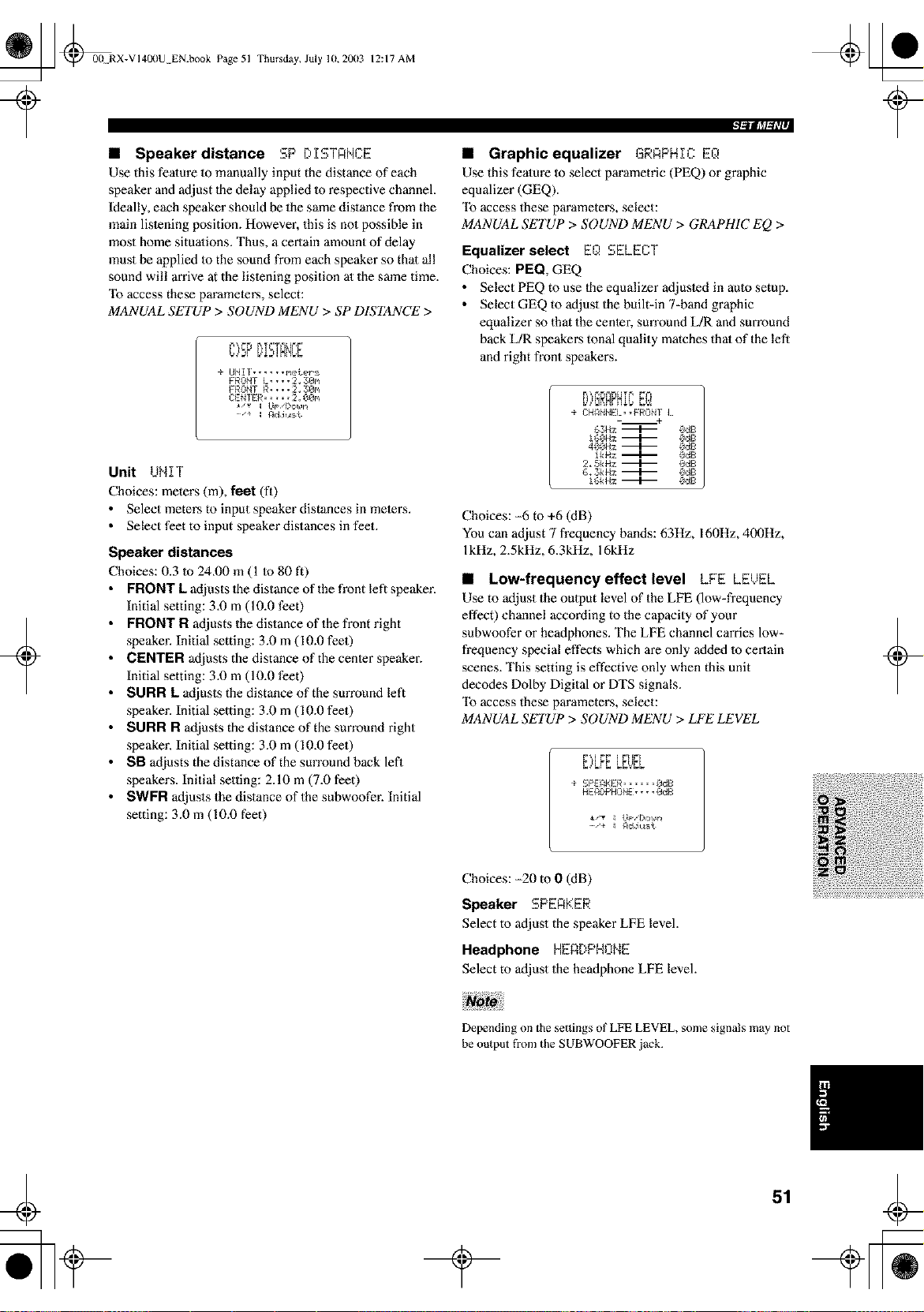
_ @00 RX-VI40I)U EN.book Page 51
?
Thursday, July 10,2003 12:17 AM
• Speaker distance SP DISTANCE
Use this fealure 1o manually input the distance of each
speaker and adjust the delay applied m respective channel.
Ideally, each speaker should be the same distance from the
main lislening position. However, this is no1 possible in
most home situations. Thus, a certain amount of delay
must be applied Io the sound from each speaker so thai all
sound will arrive at the listening position at the same time.
"Ib access these parameters, select:
MANUAL SETUP > SOUND MENU > SP DIS'IANCE >
E E _ tE tt_
+ UNIt, ..... I',etePs
FRONt L, • •• 2, :30n
FRONT R • • • • 2 _ 30_
Ck.':NIER ..... 2 __0_
+
Unit UNIT
Choices: meters (m), feet (fl)
• Select meters to input speaker distances in mete_:s.
• Select feet to input speaker distances in feet.
Speaker distances
Choices: 0.3 Io 24.00 m (1 to 80 ft)
FRONT L adjusts the distance of the front left speaker.
Initial setting: 3.0 m (10.0 feet)
FRONT R adjusts the distance of the front right
speaker. Initial setting: 3.0 m (10.0 feet)
CENTER adjusts the distance of the center speaker.
Initial setting: 3.0 m (10.0 feet)
SURR L adjusts the distance of the sun'ound left
speaker. Initial setting: 3.0 m (10.0 feet)
SURR R adjusts the distance of the sun'ound right
speaker. Initial setting: 3.0 m (10.0 feet)
SB adjusts the distance of the sun'ound back left
speakers. Initial setting: 2.10 m (7.0 feet)
SWFR adjusts the distance of the subwoofer. Initial
setting: 3.0 m (10.0 feet)
• Graphic equalizer GRRPHIC EQ
Use this feature to select parametric (PEQ) or graphic
equalizer (GEQ).
"Ib access these parameters, select:
MANUAL SETUP > SOUND MENU > GRAPHIC EQ >
Equalizer select EQ SELECT
Choices: PEQ, GEQ
• Select PEQ to use the equalizer adjusled in auto setup.
• Select GEQ to adjust the built=in 7=band graphic
equalizer so that the center, sun'ound L/R and surround
back L/R speakers tonal quality matches that of the left
and right fi'ont speakm:s.
+ CH_NNE:I.,,FRONII.
----------+
63Hz-+ OdB
160Hz+ OdB
400Hz-+ OdB
IkHz-_ OdB
2.SkHz-+ OdB
6,3kHz-+ OdB
l_kHz:-_ OdB
Choices: -6 to +6 (dB)
You can adjust 7 frequency bands: 63Hz, 160Hz, 400Hz,
lkHz, 2.5kHz, 6.3kHz, 16kHz
• Low-frequencyeffect level LFE LEUEL
Use to adjust the output level of the LFE (low-frequency
effect) channel according to the capacity of your
subwoofer or headphones. The LFE channel carries low-
fi'equency special effects which are only added 1o certain
scenes. This setting is effective only when this unit
decodes Dolby Digital or DTS signals.
"Ib access these parameters, select:
MANUAL SETUP > SOUND MENU > LFE LEVEL
WW [ _-[[M
+ SPEAKER ...... OdB
HEAl)PHONE, • • ,OdB
_/Y _ IJp,I)ol0r_
-'+ _ AdJ_isi
+
Choices: -20 to 0 (dB)
Speaker SPERKER
Select to adjust the speaker LFE level.
Headphone HERDPHONE
Select to adjust the headphone LFE level.
Depending on the settings of LFE LEVEL, some signals may not
be output fi'om the SUBWOOFER jack.
51
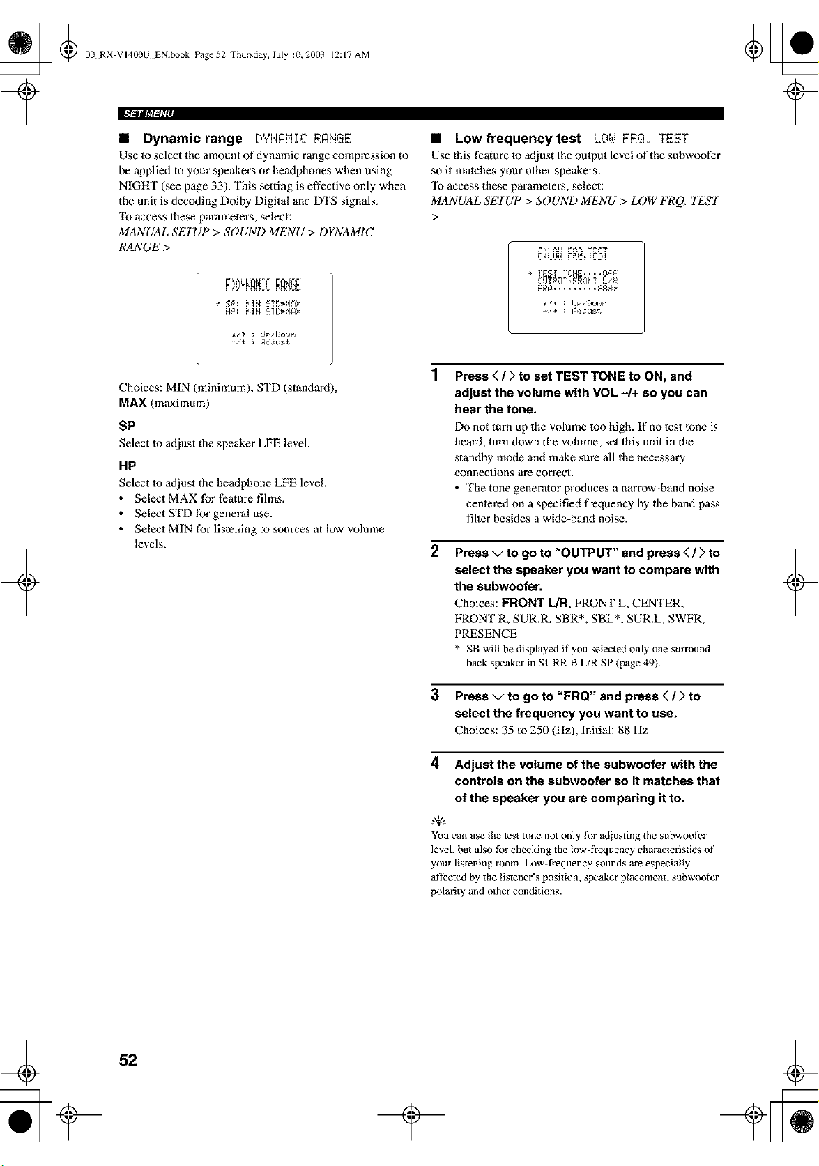
_ @00 RX-VI400U EN.book Page 52 Thursday, July 10, 20(13
12:17 AM
• Dynamic range DYNAHIC RANGE
Use 1o select the amount of dynamic range compression to
be applied to your speakers or headphones when using
NIGHT (see page 33). This setting is effective only when
the unit is decoding Dolby Digital and DTS signals.
"Ib access Ihese paramelers, select:
MANUAL SETUP > SOUND MENU > DYNAMIC
RANGE >
F'_ RI ELD'&tT_', ['_'_LD'4"
÷ SP: Hid STD_HAX
HP: HIM STD_HAX
i,g _ [JpsDor#rl
+
Choices: MIN (minimum), STD (standard),
MAX (maximum)
SP
Select to adjust the speaker LFE level.
HP
Select lo adjust the headphone LFE level.
• Select MAX for feature fihns.
• Select STD for general use.
• Select MIN for lisiening to sources at low volume
levels.
• Low frequency test LOt,.tFRO.oTEST
Use this feature 1o adjust the oulput level of the subwoofer
so it matches your olher speakers.
"Ib access these paramelers, select:
MANUAL SETUP > SOUND MENU > LOW FRQ. TEST
>
÷ TEST TONE....OFF
OUTPOT.FROHT L/R
FRO ......... ,gSH:z
_..,_- _ LIpsDor#n
-'+ _ AdJu:€
Press < / > to set TEST TONE to ON, and
adjust the volume with VOL 4+ so you can
hear the tone.
Do not turn up the volume loo high. If no lest lone is
heard, turn down the volume, set this unit in the
standby mode and make sure all the necessary
connections are correct.
• The tone generator produces a narrow-band noise
cenlered on a specified frequency by the band pass
filler besides a wide-band noise.
2
Press v to go to "OUTPUT" and press < / > to
select the speaker you want to compare with
the subwoofer.
Choices: FRONT L/R, FRONT L, CENTER,
FRONT R, SUR.R, SBR*, SBL*, SUR.L, SWFR,
PRESENCE
* SB will be displayed if you selected only one surround
back speaker in SURR B [JR SP (p_ge 49).
3 Press v to go to "FRQ" and press < / > to
select the frequency you want to use.
Choices: 35 to 250 (Hz), Initial: 88 Hz
4 Adjust the volume of the subwoofer with the
controls on the subwoofer so it matches that
of the speaker you are comparing it to.
You can use the test tone not only l_r adjusting the subwoof_r
level, but also fbr checking the low-frequency characleristics of
your listening room. Low-fiequency sounds are especially
affected by the listener's position, speaker placement, subwoofer
polarity and other conditions.
+
52
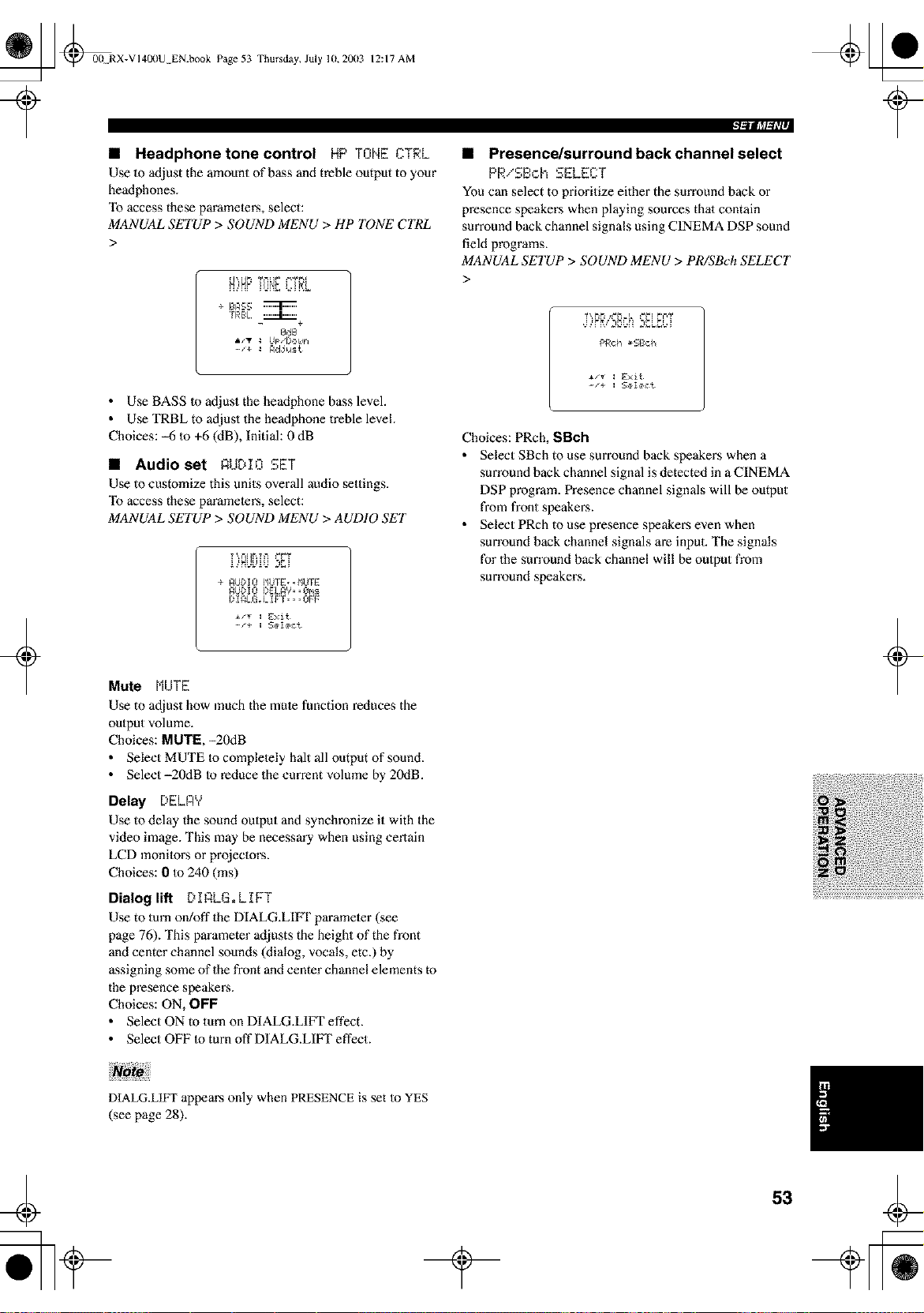
_ @00 RX-VI400U EN.book Page 53 Thursday, July lU, 20(13
+
12:17 AM
• Headphone tone control HP TONE ..T_L
Use 1o adjust the amount of bass and treble output to your
headphones.
"Ib access these paramelers, select:
MANUAL SETUP > SOUND MENU > HP TONE CTRL
>
÷ BASS
TRBL _+
0dB
-_+ : Adjust
• Use BASS to adjust the headphone bass level.
• Use TRBL to adjust the headphone treble level.
Choices: _6 to +6 (dB), Initial: 0 dB
• Audio set AUDIO SET
Use to customize this units overall audio settings.
"Ib access these paramelers, select:
MANUAL SETUP > SOUND MENU > AUDIO SET
..'..'HUL,..'u _Ei
÷ _UDIO I_UIE:,,I_UIE:
_UI)IO I)E:L_Y,•@ms
I)I_I.G_I.IF I¸_• ,OFF
• Presence/surround back channel select
PRiSB,:.h SELECT
You can select to prioritize either the surround back or
presence speakers when playing sources thai contain
surround back channel signals using CINEMA DSP sound
field programs.
MANUAL SETUP > SOUND MENU > PR/SBch SELECT
>
PRch _SBch
-/+ _ 5ete_L
Choices: PRch, SBch
• Select SBch to use surround back speakers when a
surround back channel signal is detected in a CINEMA
DSP program. Presence channel signals will be output
from front speakers.
• Select PRch to use presence speakers even when
surround back channel signals are input. The signals
for the sun'ound back channel will be output from
surround speakers.
Mute MUTE
Use to adjust how much the mule function reduces the
output volume.
Choices: NUT I_, -20dB
• Select MUTE to complelely halt all output of sound.
• Select-20dB to reduce the current volume by 20dB.
Delay [:,ELAY
Use to delay the sound oulput and synchronize it with the
video image. This may be necessm'y when using certain
LCD monilors or projectors.
Choices: 0 to 240 (ms)
Dialog lift DIQLG.LIFT
Use to turn on/off the DIALG.LIIq" parameler (see
page 76). This parameter adjusts the height of the front
and center channel sounds (dialog, vocals, etc.) by
assigning some of the front and center channel elements to
the presence speakers.
Choices: ON, OFF
• Select ON to turn on DIALG.LI_ effect.
• Select OFF to turn off DIALG.LIFI" effect.
+
DIALG.L1FT appem's only when PRESENCE is set Io YES
(see page 28).
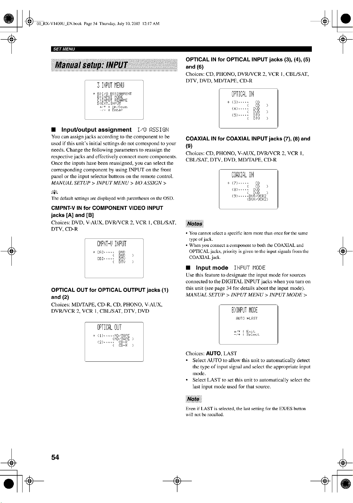
_ _00. RX-VI400UEN.bookPage54Thursday,July10,2003
12:17 AM
w _t[mt[T _ LIH
¢ A>I/O ASSI!i_NMENI
B> INPUt MODE
C>INPUt RENAME
IY>EXT. I_PUT
_/_ _ UP/Dor_ir4
/+ _ Er4ter ¸
+
• Input/output assignment I/O ASSIGN
You can assignjacksaccordinglothecomponenttobe
used if this unit's initial sellings do not correspond to your
needs. Change the following parameters to reassign the
respective jacks and effectively connect more components.
Once the inputs have been reassigned, you can select the
con'esponding component by using INPUT on the front
panel or the input seleelor buttons on the remote control.
MANUAL SETUP > INPUT MENU > 1/0 ASSIGN >
The default settings are displayed with parentheses on the OSD.
CMPNT-V IN for COMPONENT VIDEO INPUT
jacks [A] and [B]
Choices: DVD, V-AUX, DVR/VCR 2, VCR 1, CBL/SAT,
DTV, CD-R
L,I'IFI'!]%' I!'!FVI
÷ lAY ..... DUD
< DUD >
[BY..... DIU
( DIU >
OPTICAL OUT for OPTICAL OUTPUT jacks (1)
and (2)
Choices: MD/TAPE, CD-R, CD, PHONO, V=AUX,
DVR/VCR 2, VCR 1, CBL/SAT, DTV, DVD
_'_F_T%%'£ *'=HT
VF I iL,Mb UU !
÷ (I> ..... NIl I APE
<MDIIAPE >
C2> ..... _]:lY_R
OPTICAL IN for OPTICAL INPUT jacks (3), (4), (5)
and (6)
Choices: CD, PHONO, DVR/VCR 2, VCR 1, CBL/SAT,
DTV, DVD, MD_APE, CD-R
VF!!VNL
÷ <_;>..... L-:D
< CO >
(4> ..... DUD
< DUD >
(5> ..... DIO
( IYTU >
COAXIAL IN for COAXIAL INPUT jacks (7), (8) and
(9)
Choices: CD, PHONO, V-AUX, DVR/VCR 2, VCR 1,
CBL/SAT, DTV, DVD, MD/TAPE, CD-R
VVN?d_L
÷ (?> ..... CO
< CO >
(8> ..... D)D
< DUD >
( 9 >..... IYUR/UCR2
(DUR/UCR2>
• You cannot select a specific item more than once for the same
type of jack.
• When you connect a component to both the COAXIAL and
OVI'ICAL jacks, priority is given to the input signals from the
COAXIAL jack.
• Input mode INPUT MODE
Use this feature 1o designate the input mode for sources
connected m the DIGITAL INPUT jacks when you turn on
this unit (see page 34 for details about the input mode).
MANUAL SETUP > INPUT MENU > INPUT MODE >
i#!IIV! Pii.iI_I
gLlTO _LgST
i/T I E>i{
--'+ I SIll{It{
Choices: AUTO, LAST
• Select AUTO to allow this unit to automatically detect
the type of input signal and select the appropriate input
mode.
• Select LAST to set this unit to automatically select the
last input mode used for that source.
+
Even if LAST is selected, the last setting for the EX/ES button
will not be recalled.
54
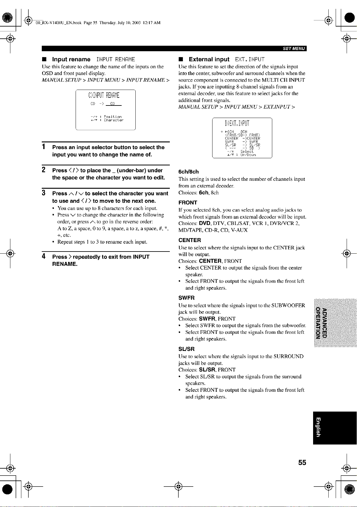
_ @00 RX-VI400U EN.book Page 55 Thursday, July 10,20(13
?
12:17 AM
• Input rename INPUT RENAME
Use this fealure 1o change the name of the inputs on the
OSD and front panel display.
MANUAL SETUP > INPUT MENU > INPUT RENAME >
Cl) - Cl)
-/+ : F'osJtJon
i/v : Chmraoter
+
1 Press an input selector button to select the
input you want to change the name of.
2 Press ( / > to place the_ (under-bar) under
the space or the character you want to edit.
3 Press/x / v to select the character you want
to use and ( / > to move to the next one.
• You can use up to 8 characters for each input.
• Press x/to change the character in the following
order, or press/x 1o go in the reverse order:
A 1o Z, a space, 0 to 9, a space, a 1o z, a space, #, *,
+, ete.
• Repeat steps 1 to 3 to rename each input.
4
Press > repeatedly to exit from INPUT
RENAME.
• External input EXT. INPUT
Use this fealure to set the direction of the signals input
inlo the center, subwoofer and surround channels when the
source component is connected 1o the MULTI CH INPUT
jacks. If you are inpuuing 8=channel signals from an
external decoder, use this feature to select jacks for the
additional front signals.
MANUAL SETUP > INPUT MENU > EX'EINPUT >
÷ _6CH 8CH
(FRNI/SS-> FRNI)
CE_IER ->CE_ IER
SI./SR - SI./SR
( .... > $8 )
-/+ Select
±/T ! Up/l)o_n
6ch/8ch
This setting is used 1o select the number of channels input
from an external decoder.
Choices: 6ch, 8ch
FRONT
If you selected 8ch, you can select analog audio jacks to
which front signals from an external decoder will be input.
Choices: DVD, DTV, CBL/SAT, VCR 1, DVR/VCR 2,
MD/TAPE, CD=R, CD, V-AUX
CENTER
Use 1o select where the signals input Io the CENTER jack
will be output.
Choices: CENTER, FRONT
• Select CENTER to output the signals from the center
speaker.
• Select FRONT to output the signals from the front lefl
and right speakers.
SWFR
Use to select where the signals input Io the S UBWOOFER
jack will be output.
Choices: SWFR, FRONT
• Select SWFR to oulput the signals from the subwoofer.
• Select FRONT to output the signals from the front lefl
and right speakers.
SL/SR
Use to select where the signals input to the SURROUND
jacks will be output.
Choices: SL/SR, FRONT
• Select SL/SR to output the signals from the surround
speakers.
• Select FRONT to output the signals from the front lefl
and right speakers.
+
55
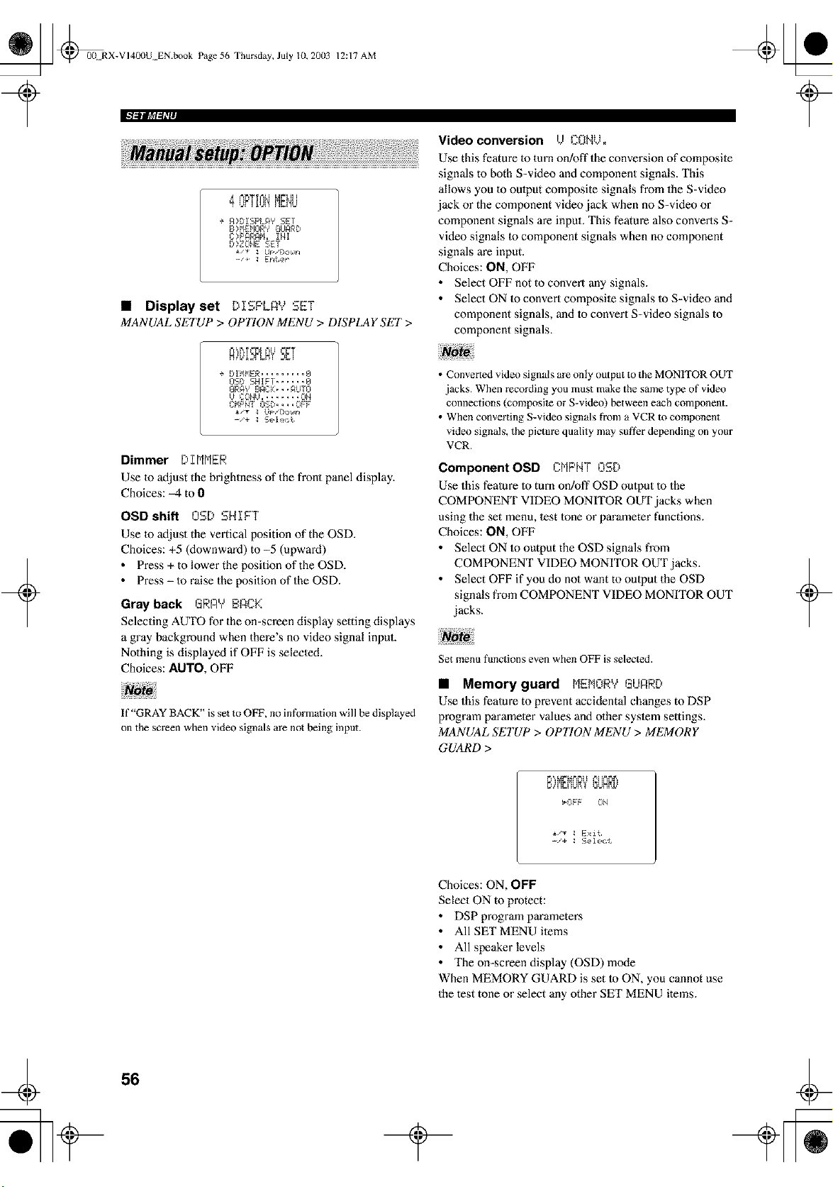
_ @0B RX-VI400U EN.book Page 56 Thursday, July 10, 20(13
12:17 AM
Video conversion U CONU.
Use this feature 1o turn on!off the conve_sion of composile
signals to both S-video and component signals. This
I IF I ! J! h_!'il.i
÷ A>DISPLAY SET
B>FIENORY GUARD
C>PARAM. INI
D>ZOHE SET
/+ _ Enter ¸
) - * iI
• Displayset [I:,FLA, SET
MANUAL SETUP > OP770N MENU > DISPLAY SET >
allows you m oulput composite signals from the S-video
jack or the component video jack when no S-video or
component signals are input. This feature also converts S-
video signals 1o component signals when no component
signals are input.
Choices: ON, OFF
• Select OFF not to convert any signals.
• Select ON 1o convert composile signals to S-video and
component signals, and lo convert S-video signals to
component signals.
+
M,<L.<I.,r.'d
÷ DIMMER......... 6
BSB SHIFT ...... @
BRA'?BACK...AUTO
B COMB........OH
CMPHT OSB....OFF
-_÷ _ Selemt
Dimmer DIMMER
Use 1o adjust the brightness of the front panel display.
Choices: _4 to 0
OSDshift OSD SHIFT
Use 1o adjust the vertical position of the OSD.
Choices: +5 (downward) to -5 (upward)
• Press + to lower the position of the OSD.
• Press - to raise the position of the OSD.
Gray back GRA'v' E,_4.+.
Selecting AUTO for the on-screen display setting displays
a gray background when there's no video signal input.
Nolhing is displayed if OFF is selecled.
Choices: AUTO, OFF
If "GRAY BACK" is set to OFF, no information will be displayed
on the screen when video signals are not being input.
• Converted video signals are only output to the MONITOR OUT
jacks. When recording yon must make the same type of video
connections (composile or S-video) between each component.
• When converting S-video signals fi'om a VCR m component
video signals, the picture quality may suf_r depending on your
VCR.
Component OSD DMPMT OSD
Use this fealure 1o tm'n on!off OSD oulput 1o the
COMPONENT VIDEO MONrI'OR OUT jacks when
using the set menu, lest tone or parameter functions.
Choices: ON, OFF
• Select ON to output the OSD signals from
COMPONENT VIDEO MONITOR OUT jacks.
• Select OFF if you do nol want to oulput the OSD
signals from COMPONENT VIDEO MONITOR OUT
jacks.
Set menu fimctions even when OFF is selected.
"1
• Memory guard bIEM._ GUnRD
Use this fealure to prevent accidental changes to DSP
program parameler values and olher syslem settings.
MANUAL SETUP > OP770N MENU > MEMORY
GUARD >
Z# I'IZI'IL_X _3L_NN_'
_OFF OH
+
i,'v : Exit
Choices: ON, OFF
Select ON to protect:
• DSP program parameters
• All SET MENU ilems
• All speaker levels
• The on=screen display (OSD) mode
When MEMORY GUARD is set to ON, you cannot use
the test tone or select any other SET MENU items.
56
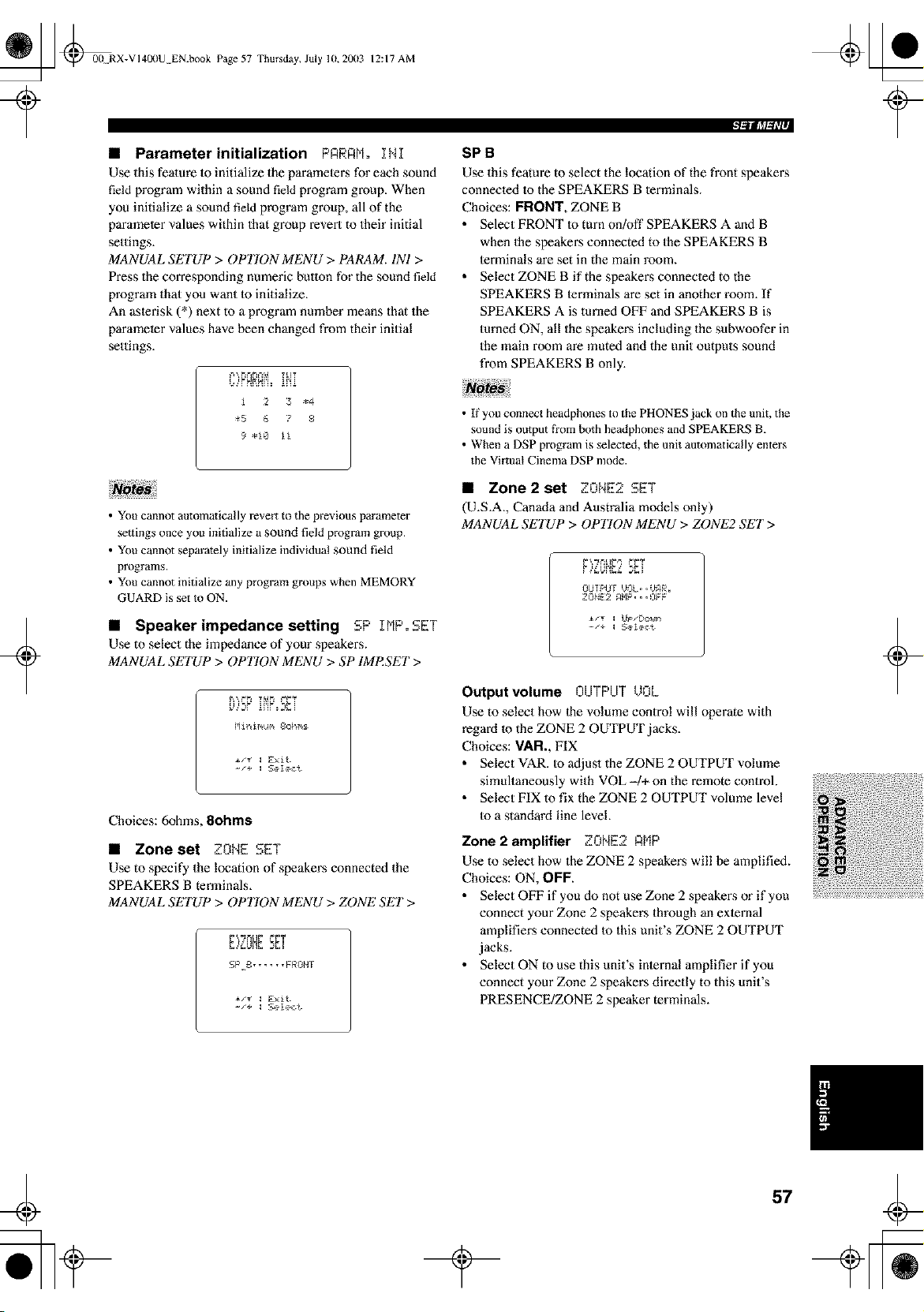
_ @00 RX-VI400U EN.book Page 57 Thursday, July 10,2003
12:17 AM
• Parameter initialization PARRM° INI
Use this fealure 1o initialize the paramelers for each sound
field program within a sound field program group. When
you initialize a sound field program group, all of the
parameter values within that group revert to their initial
settings.
MANUAL SETUP > OPTION MENU > PARAM. INI >
Press the corresponding numeric button for the sound field
program that you want to initialize.
An aslerisk (*) next to a program number means that the
parameter values have been changed from their initial
settings.
i 2 3 _4
_5 6 7 8
9 *1@ ii
+
• You cannot automatically revert to the previous parameter
settings once you initialize a sound field program group.
• You cannot separately initialize individual sound field
programs.
• You cannot initialize any program groups when MEMORY
GUARD is set to ON.
• Speaker impedance setting SP IMP.SET
Use to select the impedance of your speakers.
MANUAL SETUP > OPTION MENU > SP IMI_SET >
E [_F I[,_F _PI
HiniNum 8ohm_
-/+ : Seleot
Choices: 6ohms, 8ohms
• Zone set ZONE SET
Use to specify the location of speakers connected the
SPEAKERS B terminals,
MANUAL SETUP > OPTION MENU > ZONE SET>
_1 _ _
SPB ......FRONI
-/+ : Seleot
SPB
Use this feature to select the location of the front speakers
connected to the SPEAKERS B terminals.
Choices: FRONT, ZONE B
• Select FRONT to turn on!off SPEAKERS A and B
when the speakers connected to the SPEAKERS B
lerminals are set in the main room.
• Select ZONE B if the speakers connecled to the
SPEAKERS B terminals are set in another room. If
SPEAKERS A is turned OFF and SPEAKERS B is
turned ON, all the speakers including the subwoofer in
the main room are muted and the unit outputs sound
from SPEAKERS B only.
• If you connect headphones to the PHONES jack on the unit, the
sound is output fi'om bmh headphones and SPEAKERS B.
• When a DSP program is selected, the unit automatically enters
the Virtual Cinema DSP mode.
• Zone2 set ZONE2 SET
(U,S.A., Canada and Australia models only)
MANUAL SETUP > OPT_tON MENU > ZONE2 SET >
#,.'_u_'_Lz_Li
OUfPOf UOL..U_R.
ZONE2 _HP...OFF
-/+ : Seleot
Output volume OIJTPIJT _ ZL
Use to select how the volume control will operate with
regard m the ZONE 2 OUTPUT jacks.
Choices: VAN., FIX
• Select VAR. to adjust the ZONE 2 OUTPUT volume
simultaneously with VOL -/+ on the remote control.
• Select FIX to fix the ZONE 2 OUTPUT volume level
Io a standard line level.
Zone2 amplifier ZONE2 RMP
Use to select how the ZONE 2 speakers will be amplified,
Choices: ON, OFF.
• Select OFF if you do not use Zone 2 speakers or if you
connect your Zone 2 speakers through an exlernal
amplifiers connected to this unit's ZONE 2 OUTPUT
jacks.
• Select ON to use this unit's inlernal amplifier if you
connect your Zone 2 speakers directly to this unit's
PRESENCE/ZONE 2 speaker terminals.
t
+
57
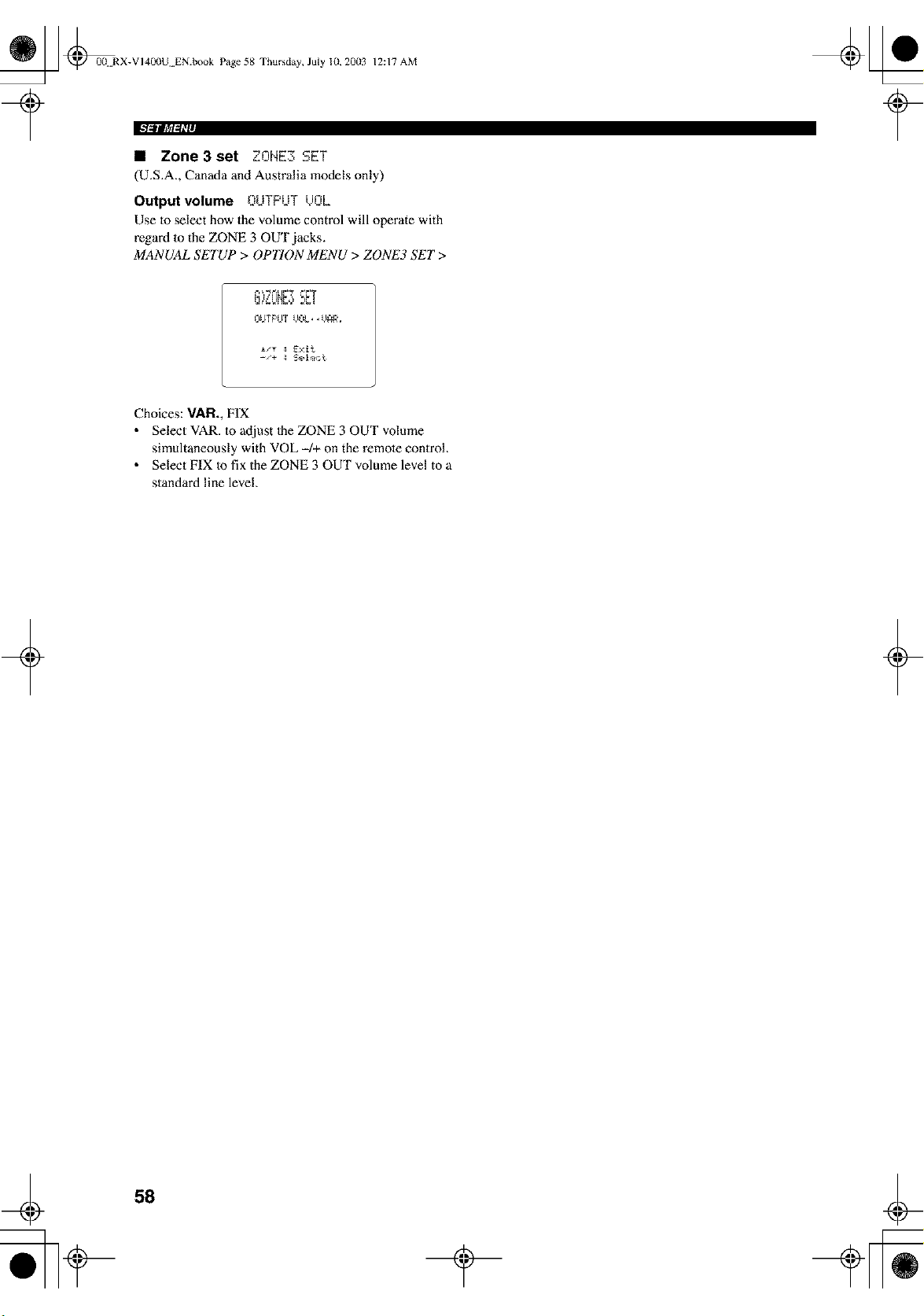
_ @0(t RX-VI400U EN.book Page 58 Thursday, July 10, 20(13
12:17 AM
• Zone3set ZONE3 SET
(U.S.A., Canada and Australia models only)
Output volume OUTPUT /JOL
Use 1o select how the volume control will operate with
regard m the ZONE 3 OUT jacks.
MANUAL SETUP > OPTION MENU > ZONE3 SET >
_-__._L[I',7 _i', T
-'÷ _ Selec_
Choices: VAR., FIX
• Select VAR. m adjust Ihe ZONE 3 OUT volume
simultaneously with VOL -/+ on the remote conirol.
• Select FIX Io fix the ZONE 3 OUT volume level to a
standard line level.
+ +
58
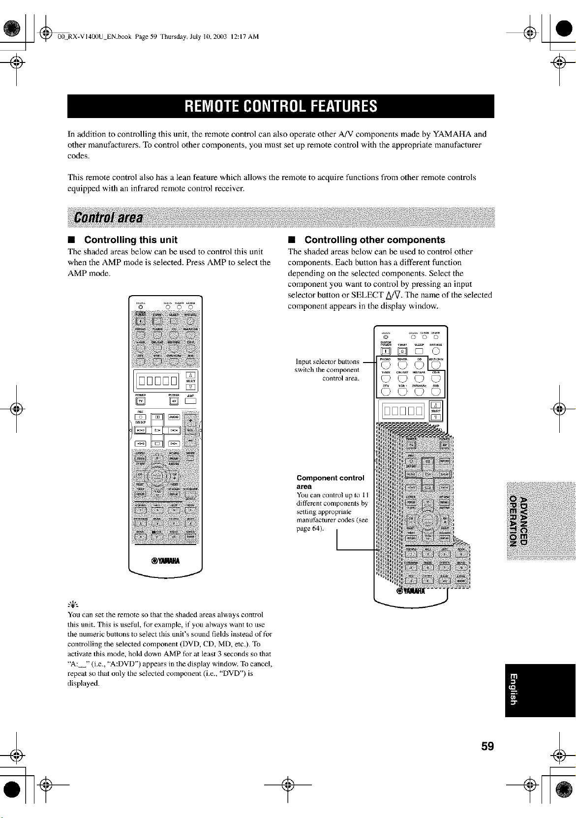
_ @00 RX-VI40(IU EN.book Page 59 Thursday, July 10,20(13
12:17 AM
t
In addition to controlling this unit, the remote control can also operate other A/V components made by YAMAHA and
other manufacturers. To control other components, you must set up remote control with the appropriate manufacturer
codes.
This remote control also has a lean feature which allows the remote to acquire functions from other remote controls
equipped with an infrared remote control receiver.
+
• Controlling this unit
The shaded areas below can be used to control this unit
when the AMP mode is selected. Press AMP to select the
AMP mode.
0 0 0
oooool
D D_
You can set the remote so that the shaded areas always control
this unit. This is use[%l, [%rexample, if you always want to use
the numeric buttons to select this unit's sound fields instead of f_r
controlling the selected component (DVD, CD, MD, etc.). To
activate this mode, hold down AMP for at least 3 seconds so tha_
"A: "(i.e., "A:DVD') appears in the display window. To cancel,
repeat so that only the selected component (i.e., "DVD') is
displayed.
• Controlling other components
The shaded areas below can be used 1o control olher
components. Each butlon has a different function
depending on the selected components. Select the
component you want to control by pressing an input
selector button or SELECT A/V. The name of the selecled
component appears in the display window.
Inputselectorhuttons--
switch the component
control area.
Component control
area
You can contro! up to 1 l
dif_%ren{ components by
se_ting appropriate
manufacturer codes (see
page 64). I--
'_° 'so'S° _S"
_DDO
©©T©
+
59
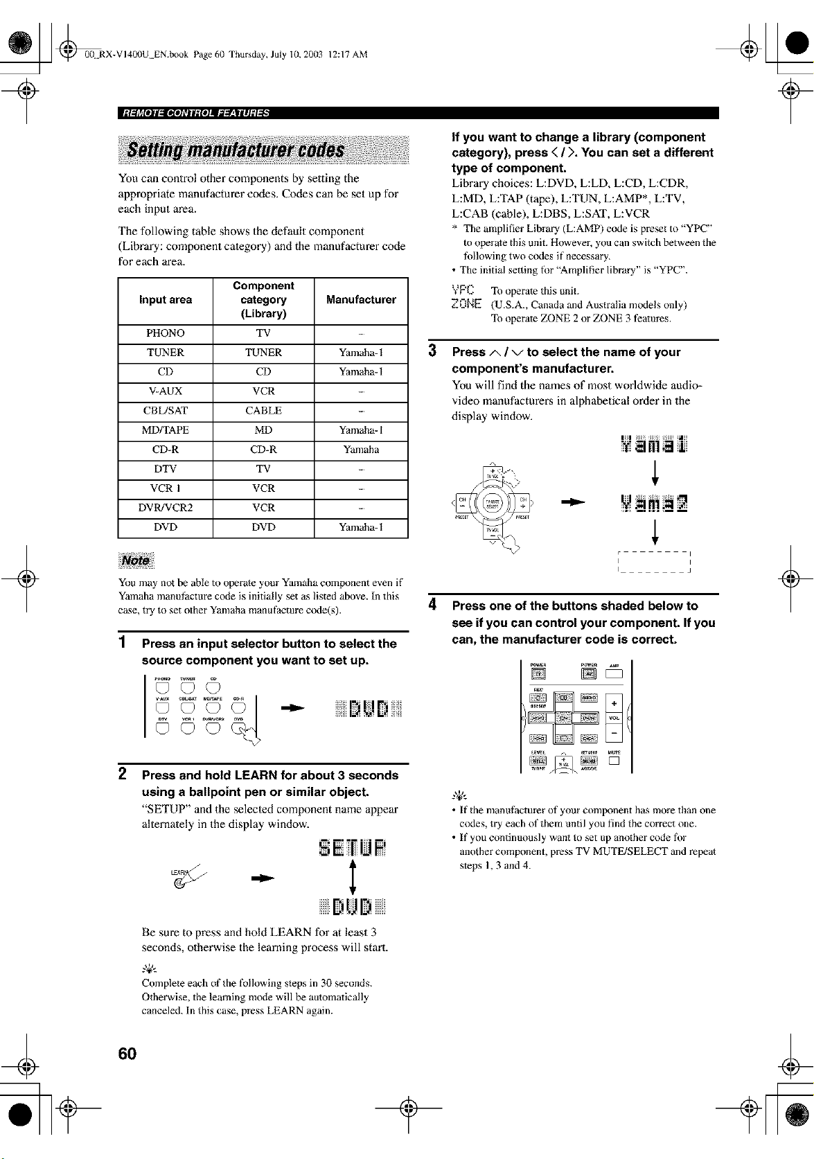
_ @00N RX-VI400U EN.book Page 60 Thursday, July 10, 20(13
12:17 AM
+
You can control other components by setting the
appropriate manufacturer codes. Codes can be set up for
each input m'ea.
The following table shows the default component
(Library: component calegory) and the manufacturer code
for each area.
Component
Input area category Manufacturer
(Library)
PHONO TV
TUNER TUNER Yamaha- 1
CD CD Yamaha- 1
V-AUX VCR
CBL/SAT CABLE
MD/TAPE MD Yamaha- 1
CD-R CD-R Yamaha
DTV TV
VCR 1 VCR -
DVR!VCR2 VCR -
DVD DVD Yamaha- 1
You may not be able to operate your Yamaha component even if
Yamaha manuf)cture code is initially set as listed above. In this
case, try to set other Yamaha manufactm'e code(s).
1 Press an input selector button to select the
source component you want to set up.
© °©" ©I r,i,r
2 Press and hold LEARN for about 3 seconds
using a ballpoint pen or similar object.
"SETUP" and the selected component name appear
alternately in the display window.
- I
BiUI)
Be sure to press and hold LEARN for at least 3
seconds, otherwise the learning process will stm't.
g+,,
Complete each of the following steps in 30 seconds.
Otherwise, the learning mode will be auiomatically
canceled. In this case, press LEARN again.
3
4
If you want to change a library (component
category), press < / ). You can set a different
type of component.
Library choices: L:DVD, L:LD, L:CD, L:CDR,
L:MD, L:TAP (tape), L:TUN, L:AMP*, L:TV,
L:CAB (cable), L:DBS, L:SAT, L:VCR
* The amplifier Library (L:AMP) code is preset to "YPC"
to operate this unit. However, you can switch between the
tMlowing two codes if necessary.
• The initial setting for "Amplifier library" is "YPC".
YPC To operate this unit.
Z0NE (U.S.A., Canada and Australia models only)
To operate ZONE 2 or ZONE 3 teaiures.
Press/x / v to select the name of your
component's manufacturer.
You will find the names of most worldwide audio=
video manufacturer,s in alphabetical order in the
display window.
r
i
I i
Press one of the buttons shaded below to
see if you can control your component. If you
can, the manufacturer code is correct.
g+,,
• If the manufacturer of your component has more than one
codes, try each of them until you find the correct one.
• If you continuously want to set up another code t_,)r
another component, press TV MUTE/SELECT and repeal
steps 1,3 and 4.
+
60
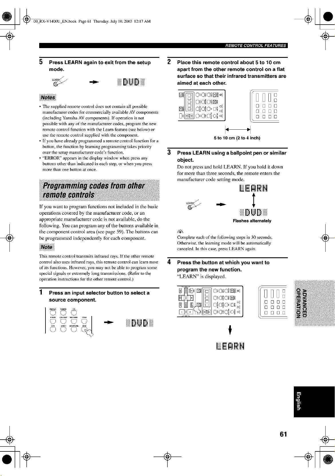
_ _00 RX-VI400U EN.book Page 61
Thursday, July 10,2003 12:17 AM
Igllrl[olll_ltioJ_TIl:fOJII;;l_'-|llJ:l'l •I
5
Press LEARN again to exit from the setup
mode.
2
Place this remote control about 5 to 10 cm
apart from the other remote control on a flat
surface so that their infrared transmitters are
aimed at each other.
• The supplied remote control does not contain all possible
manufacturer codes for commercially available AV components
(including Yamaha AV components), ff operation is not
possible with any of the manufacturer codes, program the new
remote control function with the Learn feature (see below) or
use the remote control supplied with the component.
• If you have already programmed a remote control function _k_ra
button, the function by learning programming takes priority
over the setup manufactm'er code's function.
• "ERROR" appears in the display window when press any
buttons other than indicated in each step, or when you press
more than one button at once.
8[388
8 [J88
8[3[3[3
3
5 to 10 cm (2 to 4 inch)
Press LEARN using a ballpoint pen or similar
object.
Do not press and hold LEARN. If you hold it down
for more than three seconds, the remote enlens the
manufacturer code setting mode,
+
If you want to program functions not included in the basic
operations covered by the manufacturer code, or an
appropriale manufacturer code is not available, do the
following. You can program any of the buttons available in
the component control area (see page 59). The buttons can
be programmed independently for each component.
This remote control uansmits infi'ared rays. If the other remote
control also uses infi'ared rays, this remo_e control can learn most
of its functions. However, you may not be able to program some
special signals or extxemely long transmissions. (Refer to the
operation instructions for the other remote controh)
1
Press an input selector button to select a
source component.
_T M_AOE
©oo© o
4
Flashes alternately
Complete each of the f\)llowing steps in 30 seconds.
Otherwise, the learning mode will be automatically
canceled. In this case, press LEARN again.
Press the button at which you want to
program the new function.
"LEARN" is displayed.
@o o ,
[3888
88[3[3
88[J8
f
R!q.
+
¢
61
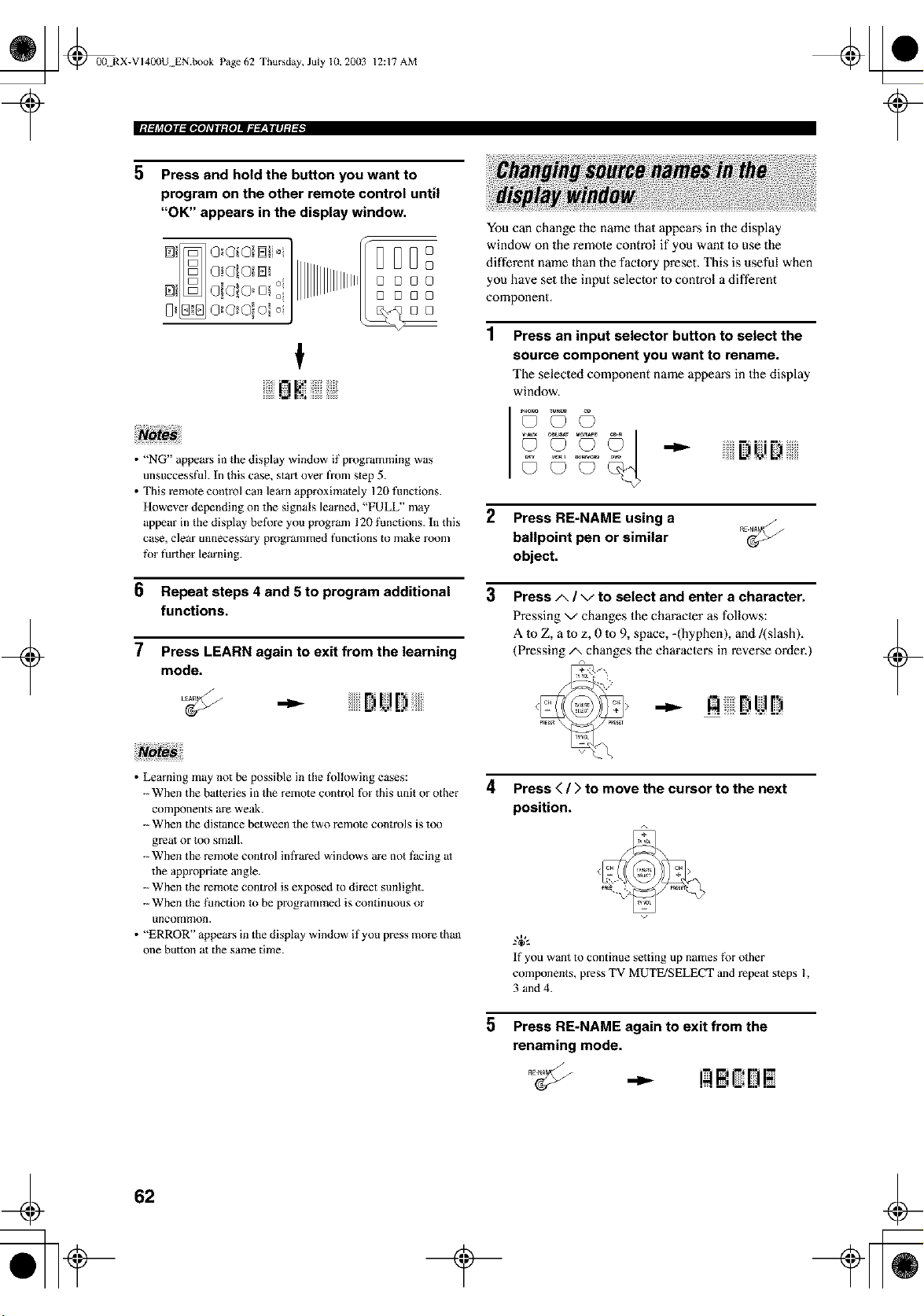
_ @00 RX-VI40(IU EN.book Page 62 Thursday, July lU, 20(13
iM,_lrll#jl,_OllTjlf_iojl_g_,Wlilj_l _ •
12:17 AM
5 Press and hold the button you want to
program on the other remote control until
"OK" appears in the display window,
BDD°
[]
[1888
[3[388
88
nl,:'!]iii;
+
• "NG" appears in the display window if programming was
unsuccessful. In this case, start over from step 5.
• This remote control can learn approximately 120 tunctions.
However depending on the signals learned, "FULL" may
appear in the display beti_re you program 120 _;anctions. In this
case, clear unnecessary programmed bmctions m make room
_\)r further learning.
6 Repeat steps 4 and 5 to program additional
functions.
7 Press LEARN again to exit from the learning
mode.
,-,.-- Dt!D
You can change the name that appears in the display
window on the remote control if you want Io use the
different name lhan the faclory preset. This is useful when
you have set the input selector to control a different
component.
Press an input selector button to select the
source component you want to rename.
The selecled component name appears in the display
window.
© o © "-"" Di.,iB
©oo¢? '
2 Press RE-NAME using a
ballpoint pen or similar
object.
3 Press/x / v to select and enter a character.
Pressing v changes the character as follows:
A 1o Z, a Io z, 0 1o9, space, -(hyphen), and/(slash),
(Pressing/x changes the characlei_s in reverse order.)
+
• Learning may not be possible in the fk)llowing cases:
-- When the batteries in the remote control fbr this unit or other
components are weak.
-- When the distance between the two remote controls is too
great or too small.
-- When the remote control infrared windows are not facing at
the appropriate angle.
-- When the remote control is exposed to direct sunlight.
-- When the _hnction _o be programmed is continuous or
/incon_n)oIl.
• "ERROR" appears in the display window if you press more than
one button at the same time.
4 Press < / > to move the cursor to the next
position.
5
If you want to continue setting up names _\)r other
components, press TV MUTE/SELECT and repeat steps 1,
3 and4.
Press RE-NAME again to exit from the
renaming mode.
¢
62
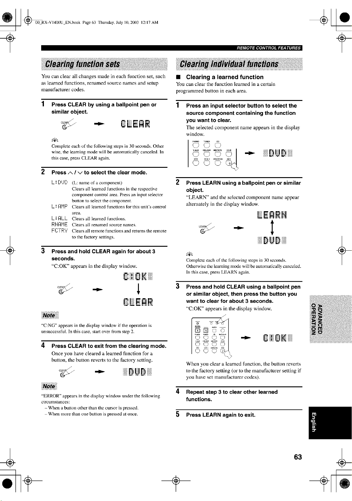
@ [fl @00 RX-VI4OI)U EN.book Page 63 Thursday, July lU, 20(13
12:17 AM
I;llrl[olll=ltloJ_TIl:fOJIl_'-|llJ:l_l •I
+
You can clear all changes made in each function set, such
as learned functions, renamed source names and setup
manufacturer codes.
1 Press CLEAR by using a ballpoint pen or
similar object.
Complete each of the tol!owing steps in 30 seconds. Other
wise, the learning mode will be automatically canceled. In
this case, press CLEAR again.
2 Press A / V to select the clear mode.
3
L_; [)t.J[) (L: name of a component)
Clears all learned functions in the respective
component control area. Press an input selector
burton {o select the component.
L.; n[']P Clears all learned fimctions tor this unit's control
area.
L.;nL.L. Clears all learned functions.
P,Nn[']E Clears all renamed source names.
FCTRY Clears all remote functions and returns the remote
to the factory settings.
Press and hold CLEAR again for about 3
seconds.
"C:OK" appears in the display window.
_i i/_iin _ ii:iiiiiil
{ !JE R
• Clearing a learned function
You can clear the function learned in a certain
programmed button in each area.
Press an input selector button to select the
source component containing the function
you want to clear.
The selected component name appears in the display
window.
2
Press LEARN using a ballpoint pen or similar
object.
"LEARN" and the selected component name appear
alternamly in Ihe display window.
- l
r., II F_
Complem each of the _\)llowing steps in 30 seconds.
Otherwise the learning mode will be automatically canceled.
In this case, press LEARN again.
3
Press and hold CLEAR using a ballpoint pen
or similar object, then press the button you
want to clear for about 3 seconds.
"C:OK" appean_ in the display window.
+
"C:NG" appears in the display window it' the operation is
unsuccessful. In this case, start over from step 2.
4 Press CLEAR to exit from the clearing mode.
Once you have cleared a learned function for a
button, the button reverts to the factory setting.
•
"ERROR" appears in the display window under the tollowing
circumstances:
-- When a button other than the cursor is pressed.
-- When more than one button is pressed at once.
When you clear a learned function, the button reverts
to the factory setting (or to the manufacturer setting if
you have set manufacturer codes).
4 Repeat step 3 to clear other learned
functions.
5 Press LEARN again to exit.
63
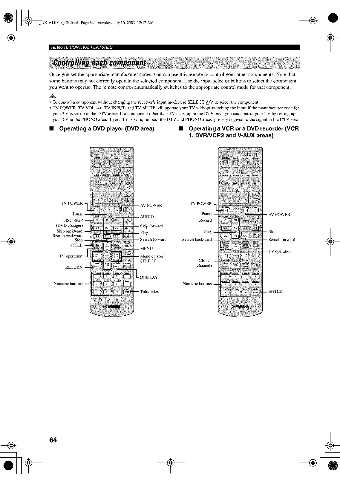
_ _0(L RX-VI400U EN.book Page 64 Thursday, July 10, 2003
12:17 AM
Once you set the appropriate manufacturer codes, you can use this remole to control your other components. Note thai
some butlons may not correctly operate the selecled component. Use the input seleclor buttons to select the component
you want Io operate. The remote control aulomatically switches Io the appropriate control mode for Ihat component.
.,+,..
• To control a component without changing the receiver's input mode, use SELECT _/V to select the component.
• TV POWER, TV VOL -4+, TV 1NPUT,and TV MUTE will operate your TV without switching the input if the manufacturer code ff_r
your TV is set up inthe DTV areas, ff a component other than TV is set up in the DTV area, you can control your TV by setting up
your TV in the PHONO area. If your TV is set up in both the DTV and PHONO areas, priority is given to the signal inthe DTV area.
• Operating a DVD player (DVD area) • Operating a VCR or a DVD recorder (VCR
1, DVR/VCR2 and V-AUX areas)
+
TV POWER -
Paus_
(DVD changer)
Ski I
TV operation -
forward
;earch forward
tlrsor/
SELECT
- DISPLAY
TV POWER
Pause
Record
Play
Search backward
CH +/
(channel)
muilleric bllttolls
+
64
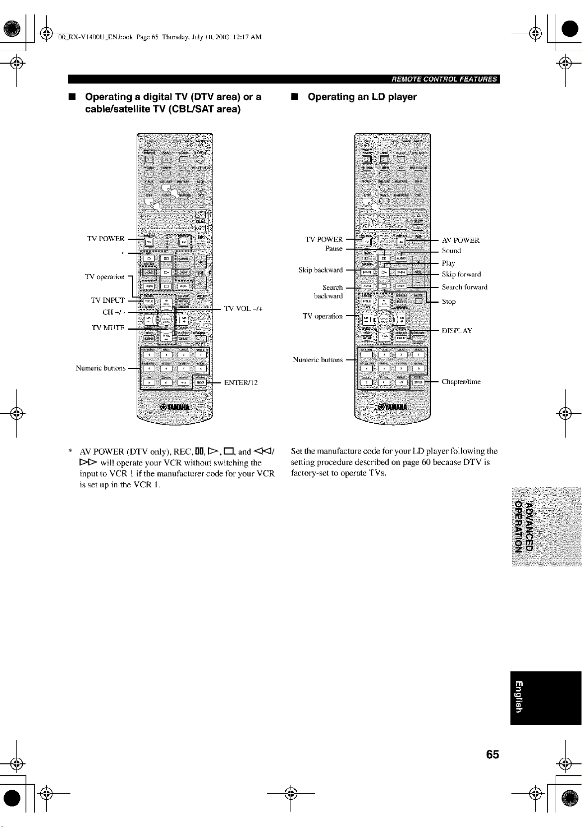
_ @0(! RX-VI40(IU EN.book Page 65 Thursday, July 1(1, 20113 12:17 AM
• Operating a digital TV (DTV area) or a
cablelsatellite TV (CBL/SAT area)
'_gll_IOII,VllfehTIl:ftlJIl=_-lv'-llllJ:l'l •l
• Operating an LD player
+
TV P
TV operation -
TV INPUT -
CH +/- --
TV MUTE --
Nt!llleric bB[tons --
-- TV VOL -/+
* AV POWER (DTV only), REC, lID,12>, F"I and <3'<1/
will operate your VCR without switching the
input Io VCR 1 if the manufacturer code for your VCR
is set up in the VCR 1.
Skip tbrward
_arch forward
backward
TVo
Numeric buttons --
Set the manufacture code for your LD player following the
setting procedure described on page 60 because DTV is
factory-set to operate TVs.
+
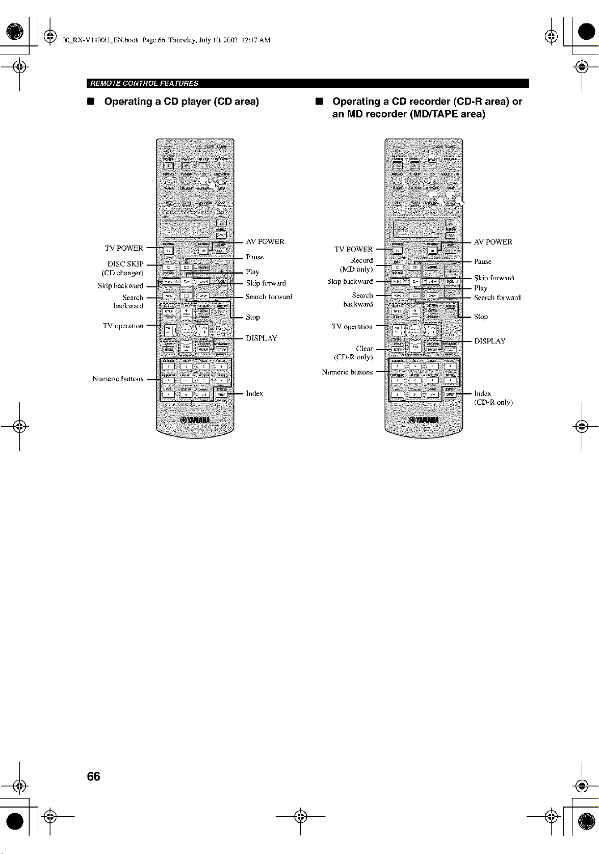
_ _00 RX-VI40(IU EN.book Page 66 Thursday, July 10, 2003
iM,_lrll#jl,_OllTjlf_iojl_g_,WliljDi _ •
12:17 AM
• Operating a CD player (CD area) Operating a CD recorder (CD-R area) or
an MD recorder (MD/TAPE area)
+
(CD change]')
Skip
backward
Nulneric bullons
Skip forward
earth forward
--Index
TVPOWER
Record
(MDonty)
Skip backward
Search
backward
TV operation
Clear
(CD-R only)
Numeric buttons
- AV POWER
_fo]w_rd
--Index
(CD-R only)
+
66
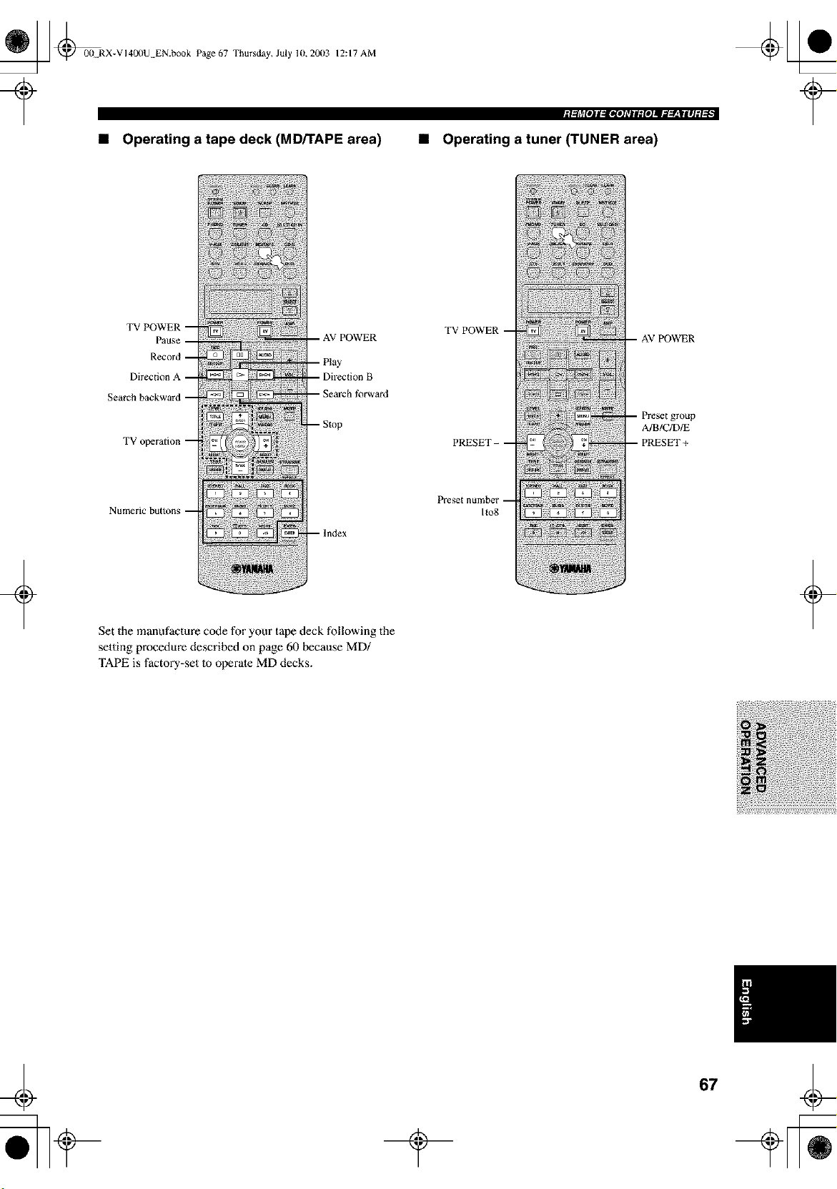
_ @00N RX-VI400U EN.book Page 67 Thursday, July 10,20(13
12:17 AM
• Operating a tape deck (MD/TAPE area)
Igllrl[olll_ltioJ_TIl:fOJII;;l_'-|llJ:l_l •I
• Operating a tuner (TUNER area)
+
Numeric button_ m
m lndex
Set the manufacture code for your tape deck following the
setting procedure described on page 60 because MD/
TAPE is factory-set to operate MD decks.
TV POWER
I1o8
A/B/C/D/E
+
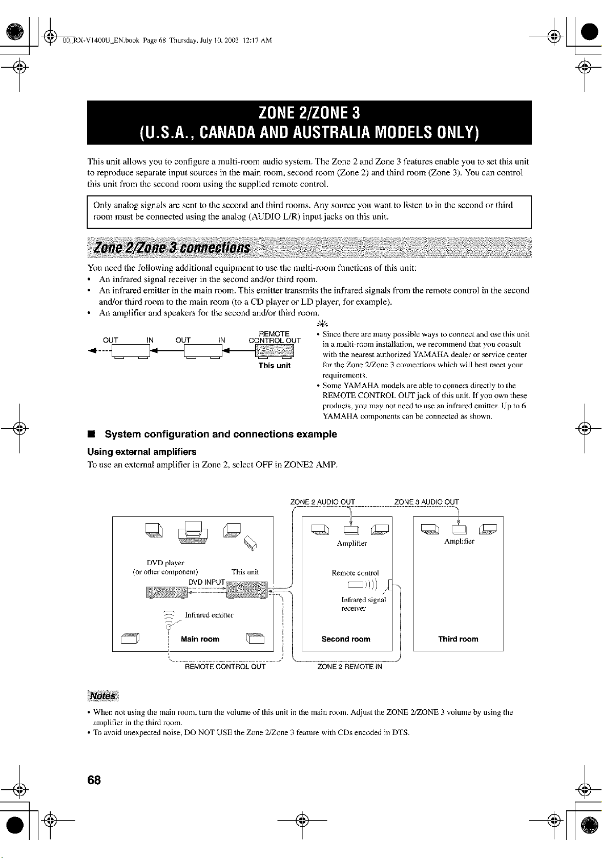
_ @00 RX-VI400U EN.book Page 68 Thursday, July 10, 20(13
12:17 AM
This unit allows you to configure a multi-room audio system. The Zone 2 and Zone 3 features enable you to set this unit
to reproduce separate input sources in the main room, second room (Zone 2) and third room (Zone 3). You can control
this unit from Ihe second room using the supplied remote control.
Only analog signals are sent to the second and third rooms. Any source you want to listen to in the second or third
room must be connected using the analog (AUDIO L/R) input jacks on this unit.
+
You need the following additional equipment Io use the multi-room functions of this unit:
• An infrared signal receiver in the second and/or third room.
• An infrared emitler in the main room. This emitler Iransmits the infrared signals from the remole control in the second
and/or third room to the main room (1o a CD player or LD player, for example).
• An amplifier and speakens for the second and/or third room.
REMOTE • Since there are many possible ways to connect and use this unit
OUT IN OUT IN CONTROL OUT in a muhi-room installation, we recommend that you consult
This unit
with the nearest authorized YAMAHA dealer or service center
fk/r the Zone 2/Zone 3 connections which will best meet your
requirements.
• Some YAMAHA models are able to connect directly to the
REMOTE CONTROL OUT jack of this unit. If you own these
products, you may not need to use an infrared emitmr. Up lo 6
YAMAHA components can be connected as shown.
• System configuration and connections example
Using external amplifiers
To use an external amplifier in Zone 2, select OFF in ZONE2 AMP.
+
ZONE 2 AUDIO OUT ZONE 3 AUDIO OUT
DVD player
(or other componen 0
This unit
Amplifier
Remole con{rol
Amplifier
Third room
REMOTE CONTROL OUT ZONE 2 REMOTE tN
• When not using the main room, turn the volume of this unit in the main room. Adjust the ZONE 2/ZONE 3 volume by using the
amplifier in the third room.
• To avoid unexpected noise, DO NOT USE the Zone 2/Zone 3 feature with CDs encoded in DTS.
68
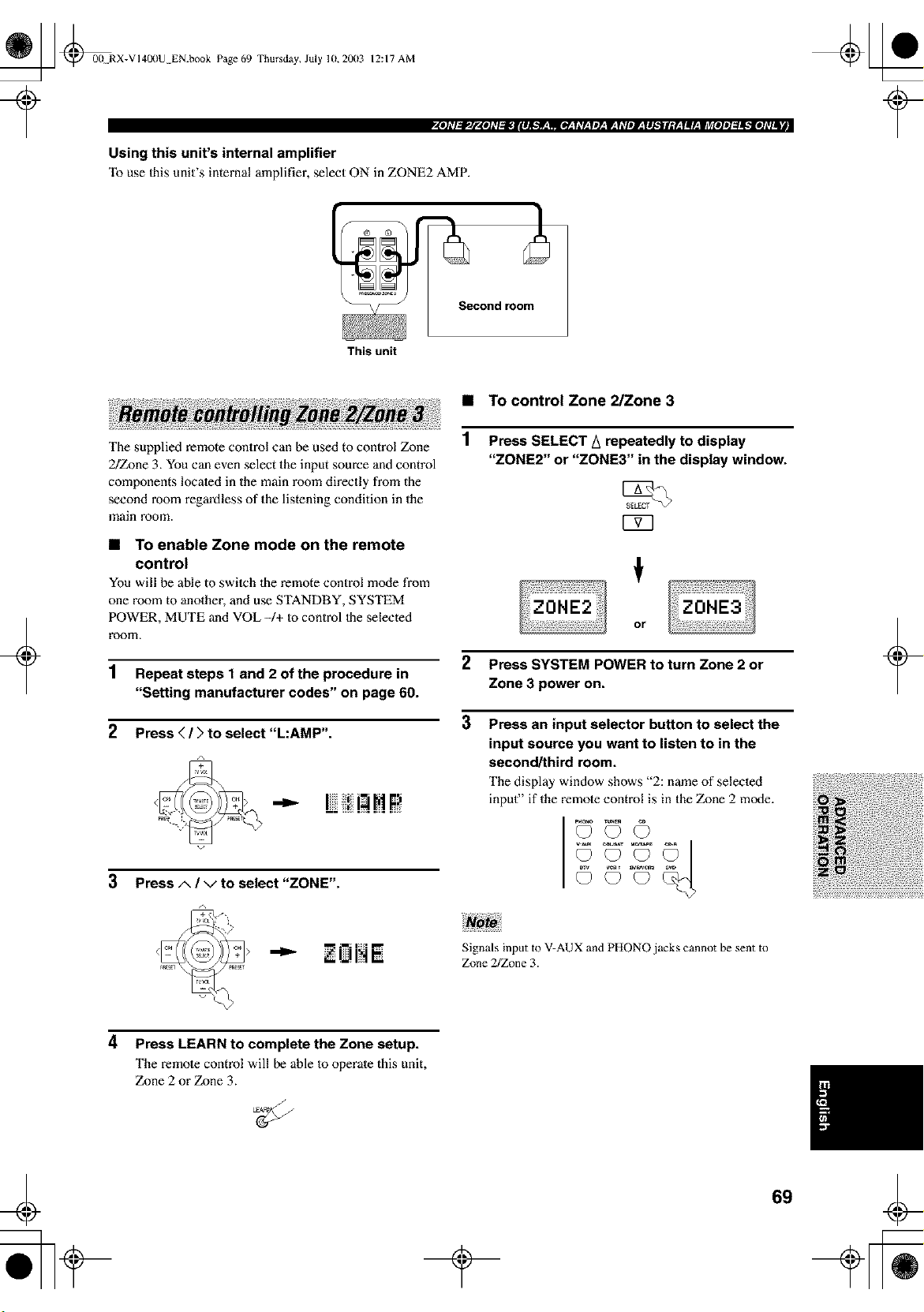
_ @00 RX-VI400U EN.book Page 69 Thursday, July 10,20(13
12:17 AM
Using this unit's internal amplifier
"Ib use Ihis unit's internal amplifier, select ON in ZONE2 AMP.
Second room
This unit
+
The supplied remote control can be used to control Zone
2/Zone 3. You can even select the input source and control
components located in the main room directly from the
second room regardless of the listening condition in the
main room.
• To enable Zone mode on the remote
control
You will be able to switeh the remote control mode from
one morn to another, and use STANDBY, SYSTEM
POWER, MUTE and VOL -/+ to control Ihe selected
room.
1 Repeat steps 1 and 2 of the procedure in
"Setting manufacturer codes" on page 60.
2 Press (/) to select "L:AMP".
12!!!HP
3 Press A / v to select "ZONE".
• To control Zone 2/Zone 3
Press SELECT A repeatedly to display
"ZONE2" or "ZONE3" in the display window.
2 Press SYSTEM POWER to turn Zone 2 or
Zone 3 power on.
3 Press an input selector button to select the
input source you want to listen to in the
second/third room.
The display window shows "2: name of selected
input" if the remote control is in the Zone 2 mode.
PH_{_ TUNE_ Q_)
+
"_ • UI"t •
Signals input to V-AUX and PHONO jacks cannot be sent to
Zone 2/Zone 3.
4 Press LEARN to complete the Zone setup.
The remote control will be able to operate this unit,
Zone 2 or Zone 3.
69
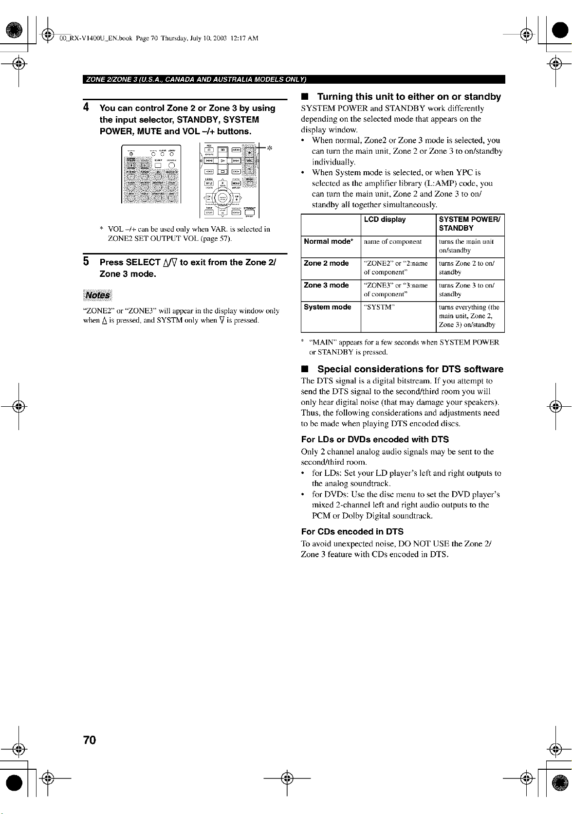
_ @0(! RX-VI40(IU EN.book Page 7(1 Thursday, July 10, 20(13 12:17 AM
4 You can control Zone 2 or Zone 3 by using
the input selector, STANDBY, SYSTEM
POWER, MUTE and VOL -/+ buttons.
2
aO
i i!i{!_!ili!il!i!ii_!ii:
5
* VOL 4+ can be used only when VAR. is selected in
ZONE2 SET OUTPUT VOL (page 57).
Press SELECT L_7 to exit from the Zone 2/
Zone 3 mode.
"ZONE2" or "ZONE3" wil! appear in the display window only
when A is pressed, and SYSTM only when V is pressed.
+
• Turning this unit to either on or standby
SYSTEM POWER and STANDBY work differently
depending on the selecled mode thai appem's on the
display window.
• When normal, Zone2 or Zone 3 mode is selected, you
can turn the main unit, Zone 2 or Zone 3 to on/standby
individually.
• When System m_xte is selected, or when YPC is
selected as the amplifier library (L:AMP) code, you
can turn 1he main unit, Zone 2 and Zone 3 to on/
standby all together simultaneously.
LCD display SYSTEM POWER/
STANDBY
Normal mode* name of component turns the main unit
on/_tandby
Zone 2 mode "ZONE2" or "2:name turns Zone 2 Io on/
of component" standby
Zone 3 mode "ZONE3" or "3:name turns Zone 3 Io on/
of component" slandby
System mode "SYSTM" turns everything (the
main unit, Zone 2,
Z_me3) on/standby
"MAIN" appears fi_r a few seconds when SYSTEM POWER
or STANDBY is pressed.
• Special considerations for DTS software
The DTS signal is a digital bitstream. If you attempt 1o
send lhe DTS signal Io the second/third room you will
only hear digital noise (that may damage your speakers).
Thus, the following considerations and adjustments need
to be made when playing DTS encoded discs.
For LDs or DVDs encoded with DTS
Only 2 channel analog audio signals may be sent to the
second/third room.
• for LDs: Set your LD player's lef_ and right oulputs to
the analog soundtrack.
• for DVDs: Use the disc menu 1o set the DVD player's
mixed 2-channel left and right audio outputs Io the
PCM or Dolby Digital soundlrack.
For CDs encoded in DTS
avoid unexpected noise, DO NOT USE the Zone 2/
Zone 3 feature with CDs encoded in DTS.
+
70
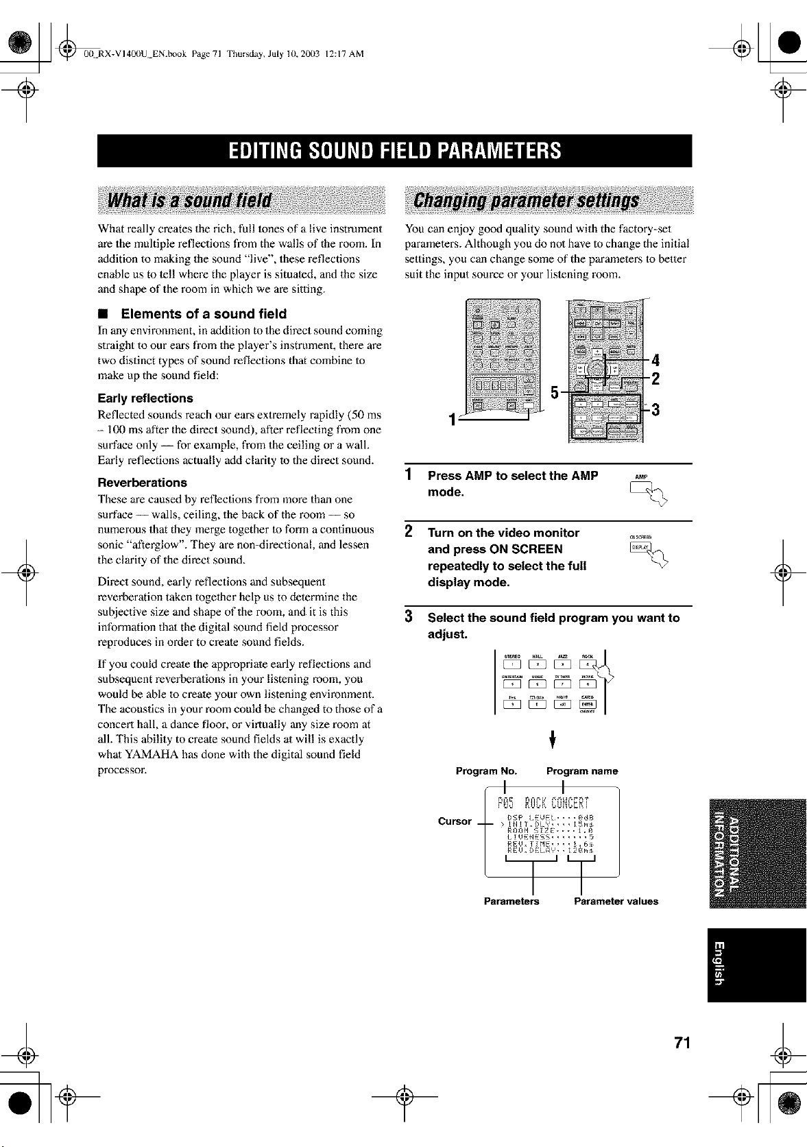
_ @0(t RX-VI40(IU EN.book Page 71
Thursday, July lU, 2003 12:17 AM
+
What really creates the rich, full lones of a live instrument
are the multiple reflections from the walls of the room. In
addition to making the sound "live", these reflections
enable us to tell where the player is situated, and the size
and shape of the room in which we are sitting.
• Elements of a sound field
In any enviromnent, in addition to the direct sound coming
slraight to our ears from the player's instrument, there are
two distinct types of sound reflections that combine Io
make up the sound field:
Early reflections
Reflected sounds reach our eai_s extremely rapidly (50 ms
- 100 ms after the direct sound), after reflecting from one
surface only -- for example, from the ceiling or a wall.
Early reflections actually add clarity Io the direct sound.
Reverberations
These are caused by reflections from more than one
surface -- walls, ceiling, the back of the room -- so
numerous that they merge together Io form a continuous
sonic "afterglow". They are non-directional, and lessen
the clarity of the direct sound.
Direct sound, early reflections and subsequent
reverberation taken togelher help us to determine the
subjective size and shape of the room, and it is this
information thai the digital sound field processor
reproduces in order to create sound fields.
If you could create the appropriate early reflections and
subsequent reverberations in your listening room, you
would be able to create your own listening environment.
The acoustics in your room could be changed to those of a
concert hall, a dance floor, or virtually any size room at
all. This ability to create sound fields at will is exactly
whal YAMAHA has done with the digital sound field
processor.
You can enjoy good quality sound with the factory-set
parameters. Although you do not have to change the initial
settings, you can change some of the parameters Io better
suit the input source or your lislening room.
_
1 Press AMP to select the AMP
mode,
2 Turn on the video monitor
and press ON SCREEN
repeatedly to select the full
display mode.
3 Select the sound field program you want to
adjust.
Program No. Program name
I I
CurSor {)f_P I EUE:L, , , , gdB
; 1111T, DLY, , , , _ [ms
Rr/gH !- _ZE, , , , J ,9
/ !UE:{IES_; .......
REU, 11HE, , , , 1,6_:_
RE:U, DE:/ flY * * _ 2Bin
Parameters Parameter values
+
_ @0(t RX-VI400U EN.book Page 72 Thursday, July 10, 20(13
12:17 AM
4 Press A / v to select
the parameters.
5
6
Press < / ) to change the
parameter value.
When you set a parameter 1oa
value other than the factory
value, an asterisk mark (*)
appears by the parameter name
on the video monitor.
Repeat steps 3 to 5 above as necessary to
change other program parameters.
+
• The available parameters may be displayed on more than one
OSD page for some of the programs. To scroll through pages,
press A / v.
• You cannot change parameter values when MEMORY GUARD
is set to "ON". If you want to change the parameter values, set
MEMORY GUARD to "OFF" (see page 56).
Memory back-up
The memory back-up circuit prevents the slored data
from being lost even if this unit is set in the standby
]node, the power cord is disconnected from the AC
outlet, or the power supply is temporarily cut due to
power failure. However, if the power is cut for more
than one week, the parameter values will return to the
factory settings. If this happens, edit the parameter
value again.
• Resetting parameters to the factory
values
To reset a certain parameter
Select the parameler you want 1o reset, then press -/+
repeatedly until the asterisk mark (*) next to the parameter
name disappem's from the video monitor.
To reset all parameters
Use PARAM.INI (see page 57).
+
72
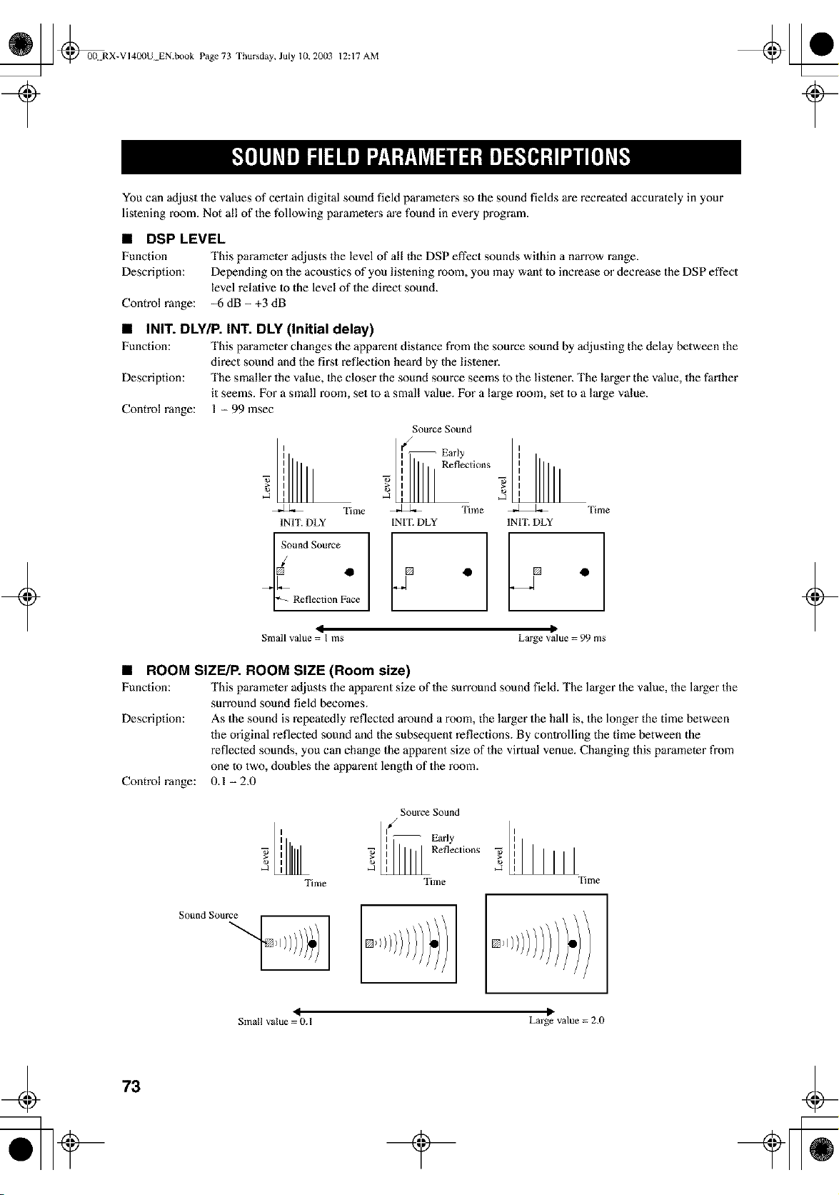
_ _0(t RX-VI400U EN.book Page 73 Thursday, July 10, 20(13
12:17 AM
+
You can adjust the values of certain digital sound field parameters so the sound fields are recreated accurately in your
listening room. Not all of the following parameters are found in every program.
• DSP LEVEL
Function This parameter adjusts the level of all the DSP effect sounds within a narrow range.
Description: Depending on the acoustics of you listening room, you may want to increase or decrease the DSP effect
level relalive 1o the level of the direct sound.
Control range: _6 dB- +3 dB
• INIT. DLYIP. INT. DLY (Initial delay)
Function: This parameter changes the apparent distance from the source sound by afljusting the delay between the
direct sound and the finest reflection heard by the listener.
Description: The smaller the value, lhe closer the sound source seems to the listener. The larger the value, the farther
it seems. For a small room, set Io a small value. For a large room, set Io a large value.
Control range: 1 - 99 msec
z
2
Time
INIT. DLY
_ound Source
g
['-_ Reflection Face
Sotlrce Sound
I Early
] i_ Reflections
Tune
INIT. DEY
i°.
Time
INIT. DLY
4 P
Small value = I ms Large value = 99 ms
• ROOM SIZE/P. ROOM SIZE (Room size)
Function: This parameter adjusts the apparent size of the surround sound field. The larger the value, the larger the
surround sound field becomes.
Description: As the sound is repeatedly reflected around a room, the larger the hall is, the longer the time between
the original reflected sound and the subsequent reflections. By controlling the time between the
reflected sounds, you can change the apparent size of the virtual venue. Changing this paramemr from
one to two, doubles the apparent length of the room.
0.1 -2.0
Control range:
Sollrce Sollnd
II ] -- Early
', _ ', Rene_Lion_
Time Time
I
Tiiiae
4
Small value = 0. I
P
Large value = 2.0
+
73
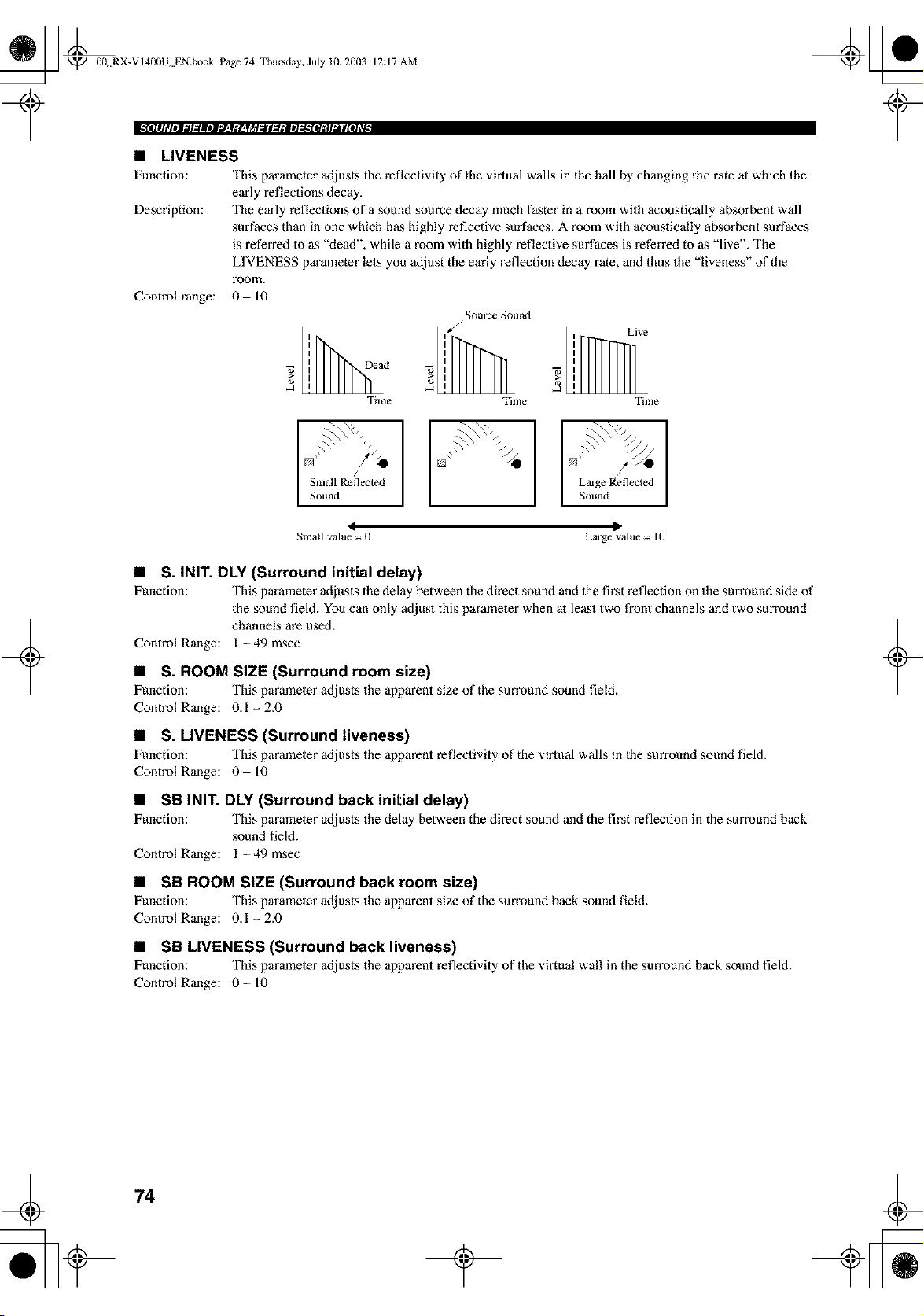
_ _00+ RX-VI400U EN.book Page 74 Thursday, July 10, 20(13
12:17 AM
• LIVENESS
Function: This parameter adjusts the reflectivity of the virtual walls in the hall by changing the rate at which the
early reflections decay.
Description: The early reflections of a sound source decay much faster in a room with acoustically absorbent wall
surfaces than in one which has highly reflective surfaces. A room with acoustically absorbent surfaces
is referred to as "dead", while a room with highly reflective surfaces is referred to as "live". The
LIVENESS parameter lets you adjust the early reflection decay rate, and thus the "liveness" of the
room.
Control range: 0- 10
1
d
Time
Source Sound
J
i Live
5
Time Time
U /'_ []
Small Reflected Large Reflected
Sound ] Sound
I D
Small value = 0 Large value = I0
+
• S. INIT. DLY (Surround initial delay)
Function: This parameter adjusts the delay between the direct sound and the first reflection on the surround side of
the sound field. You can only adjust this parameler when at least two front channels and two surround
channels are used.
Control Range: 1 -49 msec
• S. ROOM SIZE (Surround room size)
Function: This parameter adjusts the apparent size of the surround sound field.
Control Range: 0.1-2.0
• S. LIVENESS (Surround liveness)
Function: This parameter adjusts the apparent reflectivity of the virtual walls in Ihe smTound sound field.
Control Range: 0- 10
• SB INIT. DLY (Surround back initial delay)
Function: This parameler adjusts the delay between the direct sound and the first reflection in the smTound back
sound field.
Control Range: 1 -49 msec
• SB ROOM SIZE (Surround back room size)
Function: This parameter adjusts the apparent size of the surround back sound field.
Control Range: 0.1-2.0
• SB LIVENESS (Surround back liveness)
Function: This parameter adjusts the apparent reflectivity of the virtual wall in the surround back sound field.
Control Range: 0- 10
+
74
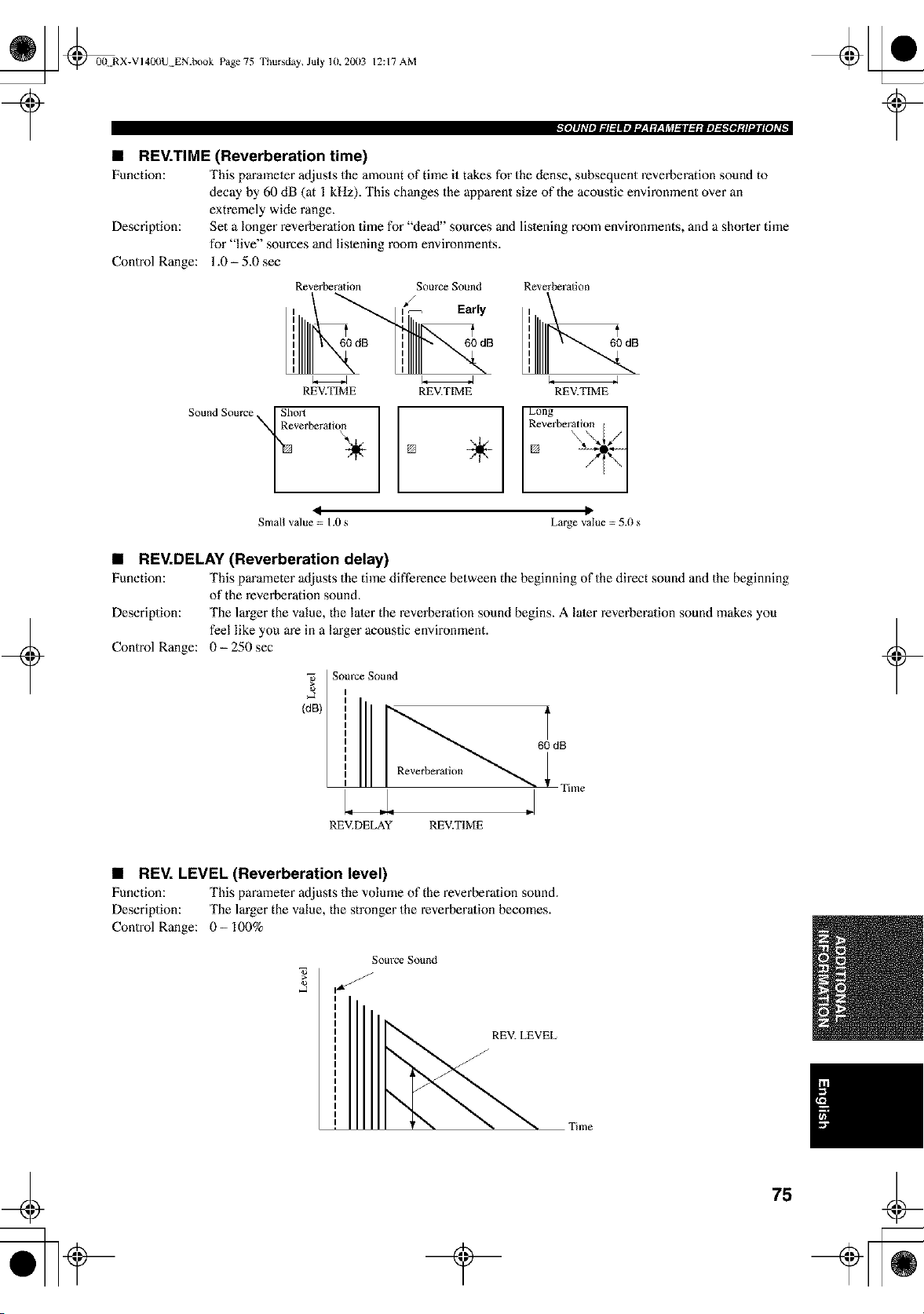
_ @0{t RX-VI400U EN.book Page 75
Thursday, July lU, 2003 12:17 AM
• REV.TIME (Reverberation time)
Function: This parameter adjusts the amount of time it takes for the dense, subsequent reverberation sound to
decay by 60 dB (at I kHz). This changes the apparent size of the acoustic environment over an
extremely wide range.
Descriplion: Set a longer reverberalion time for "dead" sources and listening room environments, and a shorter time
for "live" sources and listening room environments.
Control Range: 1.0- 5.0 see
Reverberalion Source Sound Reverberation
REV.TIME REV.TIME REV.TIME
Sound Source Sho_
verberati°_ L
60 dB
[]
I R°vneg'beratii_l__]
÷ []
< II
Small value = 1.0 s Large value = 5.0 s
+
• REV.DELAY (Reverberation delay)
Function: This parameter adjusts the time difference between the beginning of the direct sound and the beginning
of the reverberation sound.
Description: The larger the value, the later the reverberation sound begins. A later reverberation sound makes you
feel like you are in a larger acoustic environment.
Control Range: 0- 250 sec
(dB)
Som'ce Sound
60 dB
Reverbera[ion
Time
+
REV.DELAY REV.TIME
• REV. LEVEL (Reverberation level)
Function: This parameter adjusts the volume of the reverberalion sound.
Description: The larger the value, the stronger the reverberalion becomes.
Control Range: 0- 100%
Source Sound
REV. LEVEL
J
75

_ @0(t RX-VI400U EN.book Page 76 Thursday, July 10, 20(13
12:17 AM
• DIALG.LIFT (Dialog lift)
Function: This parameler adjusts the height of the front and cenler channel sounds by assigning some of the front
and cenler channel elements to the presence speakers.
Description: The larger the parameter, the higher the position of the front and cenler channel sound.
Choices: 0/112/314/5, initial setting is 3.
For 7ch Stereo
Function: These parameter adjusts the volume level for each channel in 7-channel slereo mode.
Control Range: 0- 100%
• CT LEVEL (Center level)
• SL LEVEL (Surround left level)
• SR LEVEL (Surround right level)
• SB LEVEL (Surround back level)
• PR LEVEL (Presence level)
+
For PRO LOGIC II Music
• PANORAMA
Function: Extends the front stereo image to include the surround speakers for wraparound effect.
Choices: OFF/ON, initial setting is OFF.
• DIMENSION
Function: Gradually adjusts the sound field either towards the front or towards the rear.
Control range: -3 (towards the rear) to +3 (towm'ds the front), initial setting is STD (standard).
• CT WIDTH (Center width)
Function: Adjusts the cenler image from all three front speakers to varying degrees. A larger value adjusts the
center image towards the front lefl and right speakers.
Control range: 0 (center channel sound is oulput only from cenler speaker) to 7 (cenler channel sound is output only
from front lefl and right speakers), initial setting is 3.
+
For DTS Neo:6 Music
• C. IMAGE (Center image)
Function: This parameter adjusts the center image from all three front speakers to varying degrees.
Control range: 0-0.5
For THX Cinema
• DEC (2ch Decoder Select)
Function: Selects the decoder used to playback 2-channel sources using THX Cinema.
Choices: PRO LOGIC / PLII Movie / Neo:6 Cinema
76
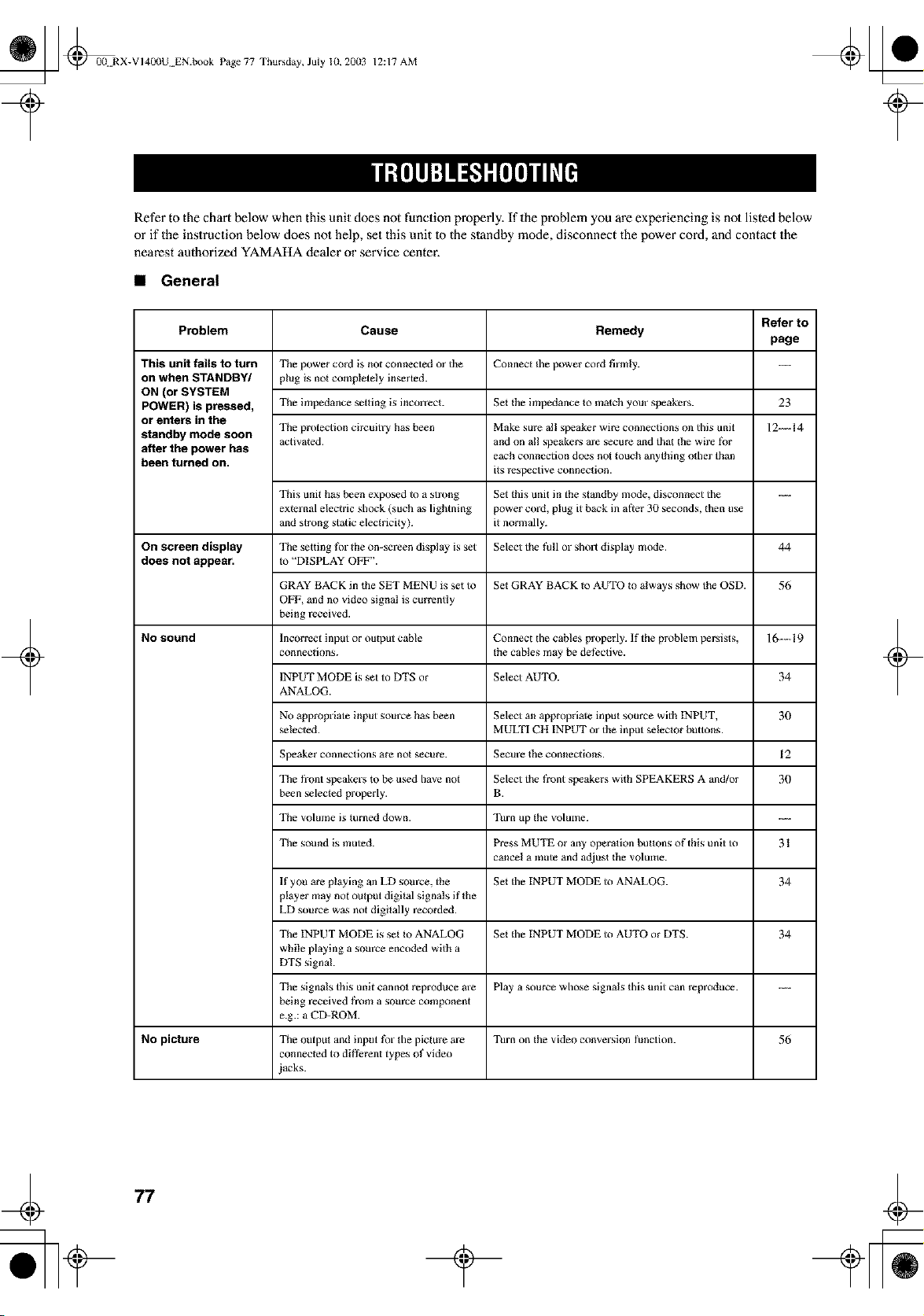
_ @0(t RX-VI400U EN.book Page 77 Thursday, July 10, 20(13
12:17 AM
Refer to the chart below when this unit does not function properly. If the problem you are experiencing is not listed below
or if the instruction below does not help, set this unit 1o the standby mode, disconnect the power cord, and contact the
nearest authorized YAMAHA dealer or service center.
• General
+
Problem
This unit fails to turn
on when STANDBY/
ON (or SYSTEM
POWER) is pressed,
or enters in the
standby mode soon
after the power has
been turned on.
On screen display
does not appear.
No sound
No picture
Cause
The power cord is not connected or the
plug is not completely inserted.
Tile impedance setting is incolTeCt.
Tile protection circuitry has been
activated.
This unit has been exposed to a strong
external electric shock (such as lightning
and strong static electricity).
Tile setting for the on-screen display is set
to "DISPLAY OFF".
GRAY BACK in the SET MENU is set to
OFF, and no video signal is currently
being received.
Incorrect input or output cable
connections.
INPUT MODE is set to DTS or
ANALOG.
No appropriate input source has been
selected.
Speaker connections are not secure.
The front speakers to be used have not
been selected properly.
Tile volume is turned down.
Tile sound is muted.
If you are playing an LD som'ce, the
player may not output digital signals if the
LD source was not digitally recorded.
Tile INPUT MODE is set Io ANALOG
while playing a som'ce encoded with a
DTS signal.
The signals this unit cannot reproduce are
being received from a source component
e.g.: a CD-ROM.
The output and input tk)r the picture are
connected to dirt?rent types of video
iacks.
Refer to
Remedy
page
Connect the power cod firmly. ----
Set the impedance to malch your speakers.
Make sure al! speaker wire connections on this unit
and on all speakers are secure and that the wire tbr
each connection does not touch anything other than
its respective connection.
Set this unit in the standby mode, disconnect the
power cord, plug it back in after 30 seconds, lhen use
it normally.
Select the fall or ShOll display mode.
Set GRAY BACK Io AUTO to always show the OSD.
Connect the cables properly. If the problem persists,
the cables may be det?ctive.
Select AUTO.
Select an appropriate input source with INPUT,
MULTI CH INPUT or the input selector buttons.
Secure the connections.
Select the front speakers with SPEAKERS A and/or
B.
Turn up the vOlulne.
Press MUTE or any operation buttons of this unit to
cancel a mute and adjust the volume.
Set lhe INPUT MODE to ANALOG.
Set lhe INPUT MODE to AUTO or DTS.
Play a source whose signals this unit can reproduce.
Turn on the video conversion function.
23
12--14
44
56
16--19
34
30
12
30
31
34
34
56
+
77
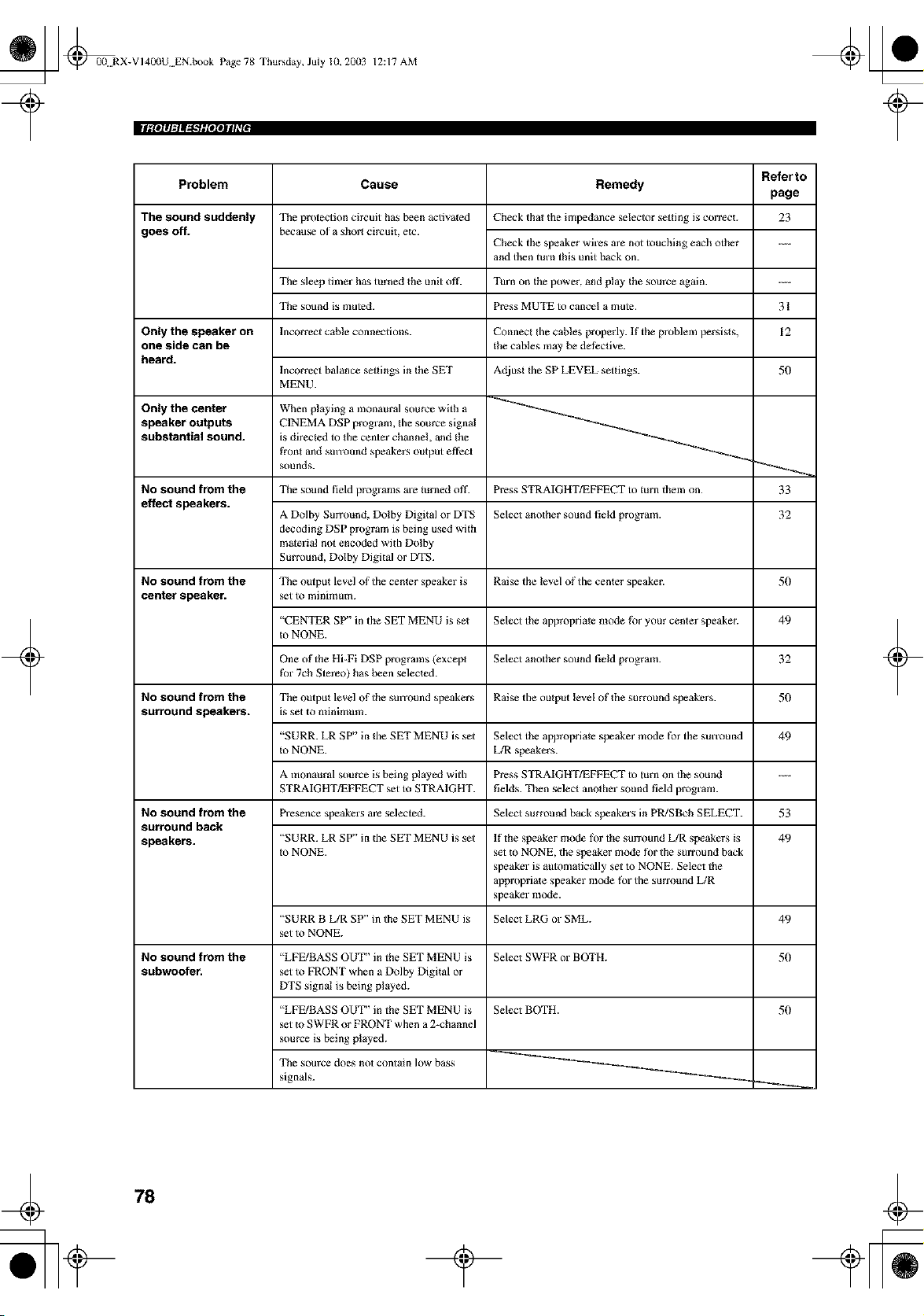
_ @00N RX-VI40(IU EN.book Page 78 Thursday, July 10, 20(13
12:17 AM
[Igl$111=tl_"_glelSJll_*$
+
Problem
The sound suddenly
goes off.
Only the speaker on
one side can be
heard.
Only the center
speaker outputs
substantial sound.
No sound from the
effect speakers.
No sound from the
center speaker.
No sound from the
surround speakers.
No sound from the
surround back
speakers.
No sound from the
subwoofer,
Referto
Cause Remedy
page
The protection circuit has been activated
because of a short circuit, etc.
Check that the impedance selector setting is correct. 23
Check the speaker wires are not touching each other ....
and then turn this unit back on.
Tile sleep tfiner has turned the unit off. Turn on the power, and play the source again.
The sound is muted. Press MUTE to cancel a mute. 31
Incorrect cable connections.
Connect the cables properly. If the problem persists,
the cables may be dethctive.
12
Incorrect balance settings in the SET
MENU.
When playing a monaural source with a
CINEMA DSP program, the source signal
is directed to the center channel, and the
front and SmTOund speakers output effect
sounds.
Adjust the SP LEVEL settings.
Tile sound field programs are turned off. Press STRAIGHT/EFFECT to turn them on.
50
33
A Dolby Surround, Dolby Digital or DTS
decoding DSP program is being used with
material not encoded with Dolby
Surround, Dolby Digital or DTS.
Select another sound field program.
32
The output level of the center speaker is Raise the level of the center speaker.
set to minimulla.
50
"CENTER SP" in the SET MENU is set Select the appropriate mode for your center speaker.
m NONE.
49
One of the Hi-Fi DSP programs (except
for 7cb Stereo) has been selected.
Select another sound field program.
32
The output level of the SmTOUnd speakers Raise the output level of the surround speakers.
is set to minimum.
50
"SURR. LR SP" in the SET MENU is set Select the appropriate speaker mode for the sun'ou nd
Io NONE. L/R speakers.
49
A monaural source is being played with Press STRAIGHT/EFFECT to turn on the sound
STRAIGHT/EFFECT set to STRAIGHT. fields. Then select another sound field program.
Presence speakers are s_U_2ted. Select surround back speakers in PR/SBcb SELECT. 53
"SURR. LR SP" in the SET MENU is set
to NONE.
If the speaker mode tbr the surround L/R speakers is
set to NONE, the speaker mode fi)r the surround back
speaker is automatically set to NONE. Select the
appropriate speaker mode for the surround L/R
speaker mode.
49
"SURR B LIR SP" in the SET MENU is Select LRG or SML.
set to NONE.
49
"LFE/BASS OUT" in the SET MENU is Select SWFR or BOTH.
set to FRONT when a Dolby Digital or
DTS signal is being played.
50
"LFE/BASS OUT" in the SET MENU is
set to SWFR or FRONT when a 2-channel
source is being played.
The som'ce does not contain low bass
signals.
Select BOTH. 50
+
78
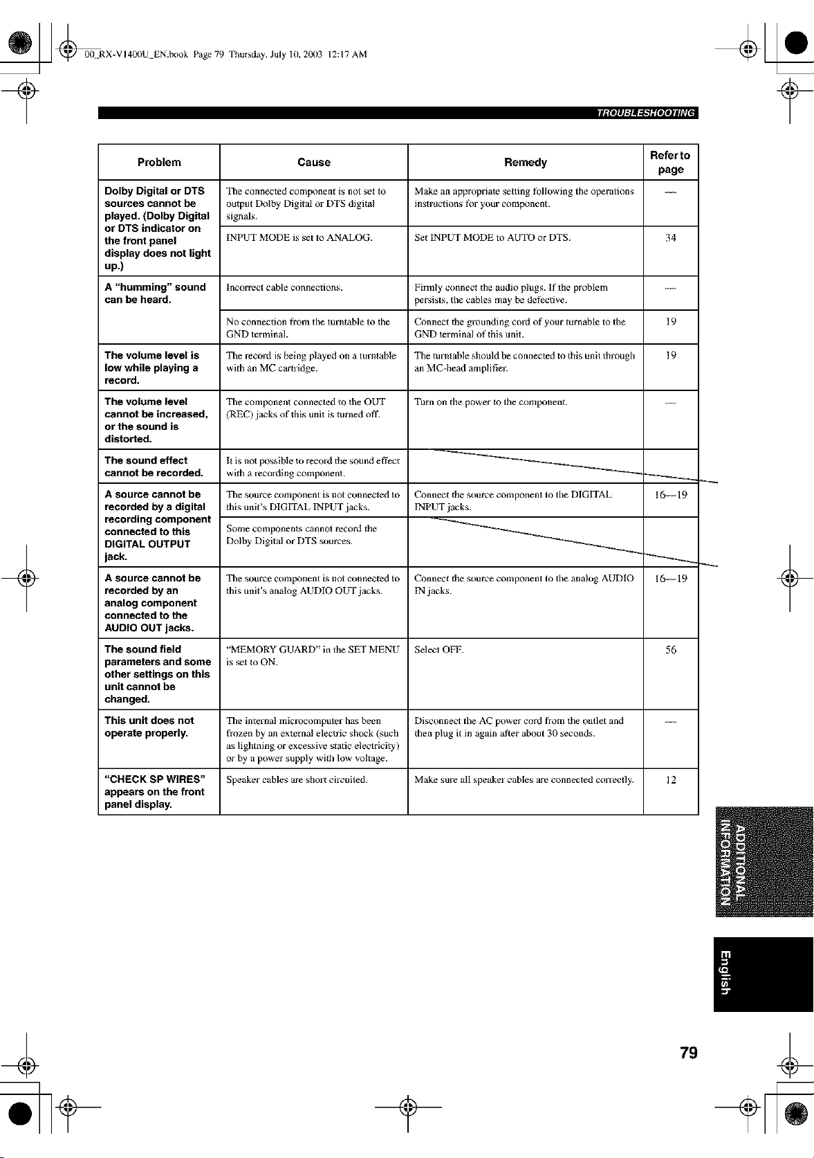
_ _00N RX-VI400U EN.book Page 79 Thursday, July 10, 20(13
12:17 AM
tilOlllgta_t."lgIOZOJlll_*I
+
Problem
Dolby Digital or DTS
sources cannot be
played. (Dolby Digital
or DTS indicator on
the front panel
display does not light
up.)
A "humming" sound
can be heard.
The volume level is
low while playing a
record.
The volume level
cannot be increased,
or the sound is
distorted.
The sound effect
cannot be recorded.
A source cannot be
recorded by a digital
recording component
connected to this
DIGITAL OUTPUT
jack.
Cause Remedy
Tile connected component is not set to
output Dolby Digital or DTS digital
signals.
INPUT MODE is set Io ANALOG.
Make an appropriate setting tbllowing the operations
instructions for your component.
Set INPUT MODE to AUTO or DTS.
Incorrect cable connections.
Firmly connect the audio plugs. If the problem
persists, the cables may be dethctive.
No connection from the turntable to 1be
GND terminal.
Connect the grounding cord of your turnable to the
GND terminal of this unit.
The record is being played on a turntable Tile turntable should be connected Io this unit through
with an MC car{ridge, an MC-head amplifier.
Tile comprment connected to the OUT
(REC) jacks of this unit is turned off.
Turn on the power _o the component.
I{ is not possible to record the sound efthct
with a recording component
Refer to
page
34
19
19
I(>---19
Tile source component is not connected Io Connect the source component to the DIGITAL
this unit's DIGITAL INPUT jacks. INPUT jacks.
Some components cannot record the
Dolby Digital or DTS sources.
A source cannot be Tile source component is not connecled Io Connect the source component to the analog AUDIO 16---19
recorded by an this unit's analog AUDIO OUT jacks. IN jacks.
analog component
connected to the
AUDIO OUT jacks.
The sound field "MEMORY GUARD" in the SET MENU Select OFF. 56
parameters and some is set to ON.
other settings on this
unit cannot be
changed.
This unit does not Tile internal microcomputer has been Disconnect the AC power cord from the outlet and ....
operate properly, frozen by an external electric shock (such then plug it in again al_er about 31) seconds.
as lightning or excessive static electricity)
or by a power supply with low voltage.
"CHECK SP WIRES" Speaker cables are short circuited. Make sure all speaker cables are connected COlTec_ly. ] 2
appears on the front
panel display,
+
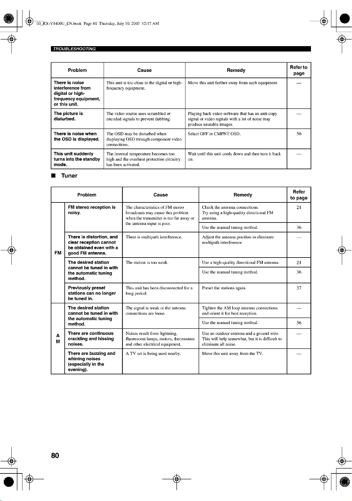
_ _00N RX-VI40(IU EN.book Page 8(I Thursday, July 10, 20(13
12:17 AM
[Igl$111=tltlt.'fglelSJlll[
Refer to
Problem Cause Remedy
page
There is noise This unit is too close to the digital or high- Move this unit fresher away tbom such equipment. ..._
interference from frequency equipment.
digital or high-
frequency equipment,
or this unit.
The picture is The video source uses scrambled or Playing back video sol,ware that has an anti-copy ........
disturbed, encoded signals to preven_ dubbing, signal or video signals with a lot of noise rrmy
produce unstable images.
There is noise when The OSD may be disturbed when Select OFF in CMPNT OSD. 56
the OSD is displayed, displaying OSD tbrough component video
connections.
This unit suddenly The internal temperature becomes too Wait until this unit cools down and tben turn it back ........
turns into the standby high and the overbear protection circuitry on.
mode. ha._ been aclivated.
• Tuner
Refer
Problem Cause Remedy to page
FM stereo reception is 21
noisy.
+
There is distortion, and
clear reception cannot
be obtained even with a
FM good FM antenna.
The desired station
cannot be tuned in with
the automatic tuning
method.
The characteristics of FM stereo
broadcasts may cause this problem
when the transinitter is too far away or
the antenna input is poor.
The desired station
cannot be tuned in with
the automatic tuning
method.
Check the antenna connections.
Try using a high-quality directional FM
antenna.
Use the manu_l tuning method. 36
There is multipath interference. Adjust the antenna position to eliminate ........
mulflp_th in_ert?rence.
The station is too weak. Use a high-quality directional FM antenna. 21
Use the manual tuning method. 36
Previously preset This unit has been disconnected ti)r a Preset the stations again. 37
stations can no longer long period.
be tuned in.
The signal is weak o1"tile antenna Tighten the AM loop antenna connections ....
connections are loose, and orien_ it _i)r best reception.
Use the manu_l tuning method. 36
A There are continuous Noises result from lightning, Use an outdoor antenna and a ground wire. ..._
crackling and hissing fluorescent lamps, motors, therinostats This will help somewhat, but it is diffficult to
M noiseS, and other electrical equipment, eliminate al! noise.
There are buzzing and A TV set is being used nearby. Move this unit away from the TV. ..._
whining noises
(especially in the
evening).
+
8O
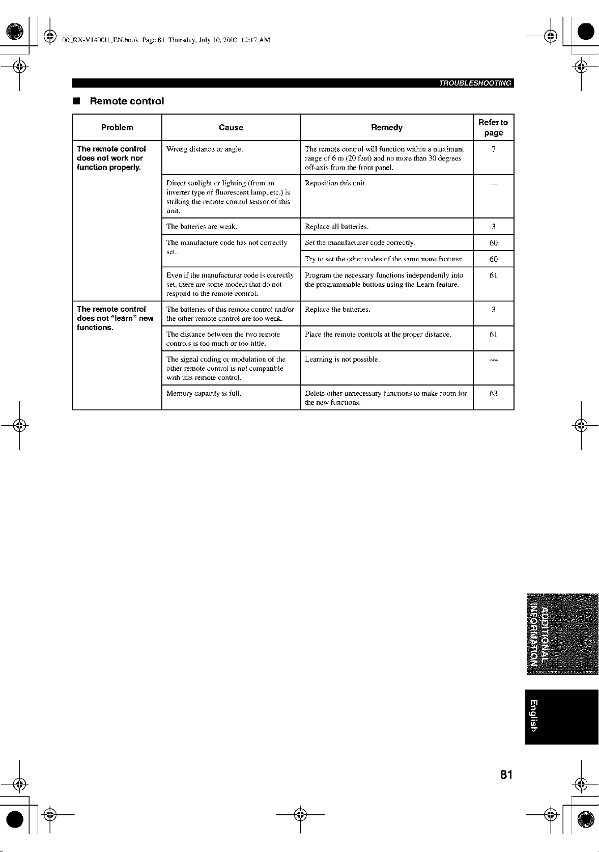
_ @00N RX-VI400U EN.book Page 81
• Remote control
Thursday, July 10,2003 12:17 AM
Referto
Problem Cause Remedy
page
The remote control Wrong distance or angle. Tile remote control will function within a maximum 7
does not work nor range ot"6 m (20 feet) and no more than 30 degrees
function properly, ofl_axis from tile front panel.
Direct sunlight or lighting (from an Reposition this unit. ---
inverter type of fluorescent lamp, elc.) is
striking the remote control sensor of this
unit.
Tbe batteries are weak.
Tbe manufacture code has not correctly
set.
+
Replace all batteries.
Set the manufacturer code correctly.
Try to s_t the other codes of the same manufacturer.
Program the necessary functions independendy into
the programmable buttons using the Learn fi_amre.
3
6O
6O
61
Even if the inantlthct urer code is correctly
set, there are some models that do not
respond Io the remote control.
The remote control Tile batteries of this remote control and/or Replace the batteries. 3
does not "lesrn" new the other remote control are too weak.
functions.
Tile distance between the two rerr_ote Place t!le remote controlg at the proper digtance. 61
controls is Ioo much or too little.
Tbe signal coding or modulation of the Learning is not possible.
other remote control is not compatible
wRh this remote control.
Memory capacRy is full. Delete other unnecessary functions Io make room f_r 63
file new functions.
+
_ @00 RX-VI400U EN.book Page 82 Thursday, July lU, 20(13
12:17 AM
+
• Dolby Surround
Dolby Surround uses a 4 channel analog recording syslem
to reproduce realistic and dynamic sound effects: 2 front
lefl and right channels (stereo), a center channel for dialog
(monaural), and a surround channel for special sound
effects (monaural). The surround channel reproduces
sound within a narrow frequency range.
Dolby Surround is widely used with nearly all video tapes
and laser discs, and in many TV and cable broadcasts as
well. The Dolby Pro Logic decoder built inlo this unit
employs a digital signal processing system thai
aulomalically stabilizes the volume on each channel to
enhance moving sound effects and directionality.
• Dolby Digital
Dolby Digital is a digital surround sound system thai gives
you completely independent multi-channel audio. With 3
front channels (left, center, and right), and 2 surround
stereo channels, Dolby Digital provides 5 full-range audio
channels. With an additional channel especially for bass
effects, called LFE (low frequency effect), the system has
a total of 5.1 channels (LFE is counted as 0.1 channel). By
using 2-channel stereo for the surround speakers, more
accurate moving sound effects and surround sound
environment are possible than with Dolby Surround. The
wide dynamic range (from maximum 1o minimum
volume) reproduced by the 5 full=range channels and the
precise sound orientation generated using digital sound
processing provide listeners with previously unheard of
excitement and realism.
With this unit, any sound environment from monaural up
to a 5. l-channel configuration can be freely selected for
your enjoyment.
Dolby Digital EX creates 6 full-bandwidth output
channels from 5. l-channel sources. This is done using a
matrix decoder that derives 3 sun'ound channels from the
2 in the original recording. For the best results, Dolby
Digital EX should be used with movie sound tracks
recorded with Dolby Digital Surround EX, With this
additional channel, you can experience more dynamic and
realistic moving sound especially with scenes with
"flyover" and "fly-around" effects.
• Dolby Pro Logic II
Dolby Pro Logic II is an improved technique used to
decode vast numbers of existing Dolby Sun'ound soflware.
This new technology enables a discrete 5- channel
playback with 2 front left and right channels, 1 center
channel, and 2 surround left and right channels (instead of
only 1 sun'ound channel for conventional Pro Logic
technology). A music mode is also available for 2-channel
sources in addition to the movie mode.
• DTS (Digital Theater Systems)
Digital Surround
DTS digital surround was developed to replace the analog
soundtracks of movies with a 6=channel digital sound
track, and is now rapidly gaining popularity in movie
theaters around the world. Digital Theater Systems Inc.
has developed a home theater syslem so that you can enjoy
the depth of sound and nalural spatial representalion of
DTS digital surround in your home. This system produces
practically distortion=free 6=channel sound (technically, a
left, right and center channels, 2 sun'ound channels, plus
an LFE 0.1 channel as a subwoofer, for a total of 5.1
channels).
The unit incorporates DTS=ES decoder thai enables 6.1-
channel reproduction by adding the surround back channel
Io existing 5. l-channel format.
• Neo:6
Neo:6 decodes the conventional 2=channel sources for 6
channel playback by the specific decoder. It enables
playback with the full-range channels with higher
separation just like digital discrete signal playback. Two
modes are available; "Music mode" for playing music
sources and "Cinema mode" for movies.
• LFE 0.1 channel
This channel is for the reproduction of low bass signals.
The frequency range for this channel is 20 Hz m 120 Hz.
This channel is counted as 0.1 because it only enforces a
low frequency range compared m the full-range
reproduced by the other 5/6 channels in a Dolby Digital or
DTS 5.1/6.1 channel systems.
• CINEMA DSP
Since the Dolby Surround and DTS systems were
originally designed for use in movie theaters, their effect
is best felt in a theater having many speakers and designed
for acoustic effects. Since home conditions, such as room
size, wall material, number of speakers, and so on, can
differ so widely, it's inevitable that there are differences in
the sound heard as well. Based on a wealth of actually
measured data, YAMAHA CINEMA DSP uses
YAMAHA original sound field technology m combine
Dolby Pm Logic, Dolby Digital and DTS systems to
provide the visual and audio experience of movie theater
in the listening room of your own home.
• SILENT CINEMA
YAMAHA has developed a natural realistic sound effect
DSP algorithm for headphones.
Parameters for headphones have been set for each sound
field so thai accurate representations of all the sound field
programs can be enjoyed on headphones.
+
82
_ @0(L RX-VI40llU EN.book Page 83 Thursday, July lU, 20(13
12:17 AM
• Virtual CINEMA DSP
YAMAHA has developed a Virtual CINEMA DSP
algorithm Ihat allows you 1o enjoy DSP sound field
surround effects even without any surround speakers by
using virtual sun'ound speakers.
It is even possible 1o enjoy Virtual CINEMA DSP using a
minimal two-speaker system thai does not include a center
speaker.
• Composite Video signal
With the composite video signal system, the video signal
is composed of three basic elements of a video picture;
color, brightness and synehronizalion data. A composite
video jack on a video component transmits these three
elements combined.
• S VIDEO signal
With the S VIDEO signal system, the video signal
normally transmitted using a pin cable is separated and
transmitted as the Y signal for the luminance and the C
signal for the chrominance through the S VIDEO cable.
Using the S VIDEO jack eliminates video signal
transmission loss and allows recording and playback of
even more beautiful images.
+
• Component video signal
With the component video signal system, the video signal
is separated into the Y signal for the luminance and the P_
and P[_ signals for the ehrominance. Color can be
reproduced more faithfully with this syslem because each
of these signals is independent. The component signal is
also called lhe "color difference signal" because the
luminance signal is sublracted from the color signal.
A monitor with component input jacks is required in order
to use the component signal for output.
• PCM (Linear PCM)
Linear PCM is a signal format under which an analog
audio signal is digitized, recorded and transmitted without
using any compression. This is used as a method of
recording CDs and DVD audio. The PCM system uses a
technique for sampling the size of the analog signal per
very small unit of time. Standing for "pulse code
modulation", the analog signal is encoded as pulses and
then modulated for recording.
• Sampling frequency and number of
quantized bits
When digitizing an analog audio signal, Ihe number of
times the signal is sampled per second is called the
sampling frequency, while the degree of fineness when
converting the sound level inlo a numeric value is called
the number of quantized bits.
The range of rates that can be played back is determined
based on the sampling rate, while the dynamic range
representing the sound level difference is determined by
the number of quantized bits. In principle, the higher lhe
sampling frequency, the wider the range of frequencies
that can be played back, and the higher the number of
quantized bits, the more finely the sound level can be
reproduced.
• THX Cinema processing
THX is an exclusive set of standards and technologies
established by the world-renowned film production
company, Lueasfihn Ltd. THX grew from George Lucas'
personal desire Io make your experience of the fihn
soundtrack, in both movie theatres and in your home
theatre, as faithful as possible to what the director
intended.
Movie soundtracks are mixed in special movie theatres
called dubbing stages and are designed to be played back
in movie theatres with similar equipment and conditions.
This same soundtrack is then transferred direclly omo
Laserdisc, VHS tape, DVD, etc., and is not changed for
playback in a small home theatre environment.
THX engineers developed patented technologies 1o
accurately translate 1he sound from the movie theatre
environment inlo 1he home, correcting the tonal and
spatial errors that occur. On this product, when the THX
indicator is on, THX fealures are automatically added in
Cinema modes (e.g. THX Cinema, THX Surround EXt.
• Re-Equalization
The lonal balance of a fihn soundtrack will be excessively
bright and harsh when played back over audio equipment
in the home because fihn soundtracks were designed to be
played back in large movie theatres using very different
professional equipment. Re-Equalization restores the
correct lonal balance for watching a movie soundtrack in a
small home environment.
• Timbre Matching
The human ear changes our perception of a sound
depending on the direction from which the sound is
coming. In a movie theatre, there is an array of sun'ound
speakers so that the surround information is all around
you. In a home theatre, you use only two speakers located
to the side of your head. The Timbre Matching feature
filters the information going to the surround speakers so
that they more closely match lhe tonal characteristics of
the sound coming from 1he front speakers. This ensures
seamless panning between the front and surround
speakers.
+
_ @00N RX-VI40(IU EN.book Page 84 Thursday, July 10, 20(13
+
12:17 AM
• Adaptive Decorrelation
In a movie theatre, a large number of surround speakers
help create an enveloping surround sound experience, but
in a home theatre there are usually only two speakers. This
can make the surround speakers sound like headphones
that lack spaciousness and envelopment. The surround
sounds will also collapse into the closest speaker as you
move away from the middle seating position. Adaptive
Decon'elation slightly changes one surround channel's
time and phase relationship with respect to the other
surround channel. This expaods the listening position and
creates-=with only two speakers--the same spacious
surround experience as in a movie theatre.
• THX Select
Before any home theatre component can be THX Select
certified, it must incorporate all the features above aod
also pass a rigorous series of quality and performance
tests. Only then can a product feature the THX Select
logo, which is your guarantee that the Home Theatre
products you purchase will give you superb performance
for many years to come. THX Select requirements cover
every aspect of the product including power amplifier and
pre-amplifier performance and operation, and hundreds of
other parameters in both the digital and analog domain.
• THX Surround EX
THX Surround EX - Dolby Digital Surround EX is a joint
development of Dolby Laboratories and the THX Ltd.
In a movie theater, fihn soundlracks that have been
encoded with Dolby Digital Sun'ound EX technology are
able to reproduce an extra channel which has been added
during the mixing of the program. This channel, called
Sun'ound Back, places sounds behind the listener in
addition to Ihe currently available front left, front cenler,
front right, sun'ound right, surround left and subwoofer
channels. This additional channel provides the opportunity
for more detailed imaging behind the listener and brings
more depth, spacious ambience and sound localization
than ever before.
Movies thai were created using the Dolby Digital
Surround EX technology, when released into the home
consumer market may exhibit wording to thai effect on the
packaging. A list of movies created using this lechnology
can be found on Ihe Dolby web sile at www.dolby.com. A
list of available DVD soflware titles encoded with this
lechnology can be found at www.thx.com.
Only receiver and controller products bearing the THX
Sun'ound EX logo, when in the THX Sun'ound EX mode,
faithfully reproduce this new technology in the home.
This product may also engage the THX Surrouod EX
mode during the playback of 5.1 channel material thai is
no1 Dolby Digital Sun'ound EX encoded. In such case the
information delivered to Ihe Surrouod Back channel will
be program dependent and may or may no1 be very
pleasing depending on the particular sounOrack and the
tastes of the individual lislener.
• ITU-R
ITU-R is the radio communication sector of the ITU
(lnlernafional Telecommunication Union). ITU-R
recommends a standard speaker placement which is used
in many critical lislening rooms, especially for mastering
purposes.
+
84
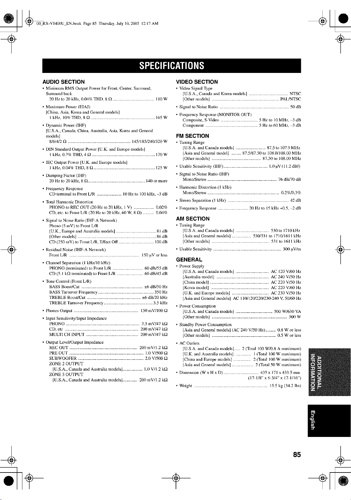
_ @00N RX-VI400U EN.book Page 85
Thursday, July 10, 20(13 12:17 AM
+
AUDIO SECTION
• Minin'mm RMS Output Power t_r Front Center, SmTound
Surround back
20 Hz to 20 kHz, 0.04% THD, 8 _ ..................................... I10W
• Maximum Power (EIAJ)
[China, Asia, Korea and General models]
1 kHz, 10% THD, 8 _ .......................................................... 165W
• Dynamic Power (IHF)
[U.S.A., Canada, China, Australia, Asia, Korea and Genera!
models]
8/6/4/2 _ ........................................................ 145/I 851240/320 W
• DIN Standard Output Power [U.K. and Europe models]
I kHz, 0.7% TI-ID, 4 _ ......................................................... 170 W
• IEC Output Power [U.K. and Europe models]
1 kHz, 0.04% THD, 8 g_ ....................................................... 125W
• Damping Factor (IHF)
20 Hz Io 20 kHz, 8 _ ................................................... 140 or more
• Frequency Response
CD terminal to Front L/R ...................... 10Hzto 100kHz, 3dB
• Total Harmonic Distortion
PHONO to REC OUT (21) Hz _o 21) kttz, 1 V) .................. 0.t)2%
CD, etc. to Front L/R (20 Hz to 20 kHz, 60 W, 8 _) .......... 0.04%
• Signa! to Noise Ratio (IItF-A Network)
Phono (5 mV) to Front L/R
[U.K., Europe and Australia models] .................................... 81 dB
IOther modelst ....................................................................... 86 dB
CD (250 mV) to Front L/R, Effect Off ................................ 100 dB
• Residual Noise (IHF-A Network)
Fron_ L/R ............................................................... 150 g_V or less
• Channel Separation (1 kHzJl0 kHz)
PHONO (terminated) to Front L/R ........................... 60 dB/55 dB
CD (5.1 k_ terxnina_ed) to Front L/R ....................... h0 dB/45 dB
• Tone Control (Front L/R)
BASS BoosffCu_ ....................................................... ±6 dB/50 Hz
BASS Turnover Frequency .................................................. 350 Hz
TREBLE Boost/Cut ................................................ ±h dB/20 kHz
TREBLE Turnover Frequency ............................................ 3.5 kHz
• Phones Ou_ptlt .......................................................... 150 mV/100
• Input Sensitivity/Input Impedance
PHONO .................................................................. 3.5 mV/47 k_
CD, elc .................................................................. 200 mV/47 k_
MULTI CH INPUT ............................................... 200 mV/47 k_
• Output Level/Output Impedance
REC OUT ............................................................. 200 mV/! .2 k_
PRE OUT ................................................................... 1.1)V/500
SUBWOOFER ........................................................... 2.0 V/500
ZONE 2 OUTPUT
IU.S.A., Canada and Australia models] .................. 1.0 V/1.2 k_
ZONE 3 OUTPUT
[U.S.A., Canada and Australia models] ............. 200 mV/1.2 k_
VIDEO SECTION
• Video Signal q_Jpe
IU.S.A. Canada and Korea models] ................................... NTSC
lOther models] ............................................................ PAL/NTSC
• Signal to Noise Ratio .............................................................. 50 dB
• Frequency Response (MONITOR OUT)
Composite, S-Video ................................. 5 Hz Io 10 MHz, -3 dB
Component ............................................... 5 Hz Io 60 MHz, -3 dB
FM SECTION
• Tuning Range
[U.S.A. and Canada models] ........................... 87.5 to 107.9 MItz
[Asia and General model] ......... 87.5187.50 to 108.0/108.00 MItz
[Other models] ............................................ 87.50 Io 108.00 MItz
• Usable Sensitivity (IHF) ........................................ 1.0 pV ( 1 ! .2 dBf)
• Signal to Noise Rmio (IHF)
Mono/Stereo .............................................................. 76 dB/70 dB
• Harmonic Distollion (I kHz)
Mono/Stereo ................................................................ 0.2%1f1.3%
• Stereo Separation (1 kHz) ....................................................... 42 dB
• Frequency Response ........................... 20 Hz m 15 kHz +/).5, _ dB
AM SECTION
• Tuning Range
[ U.S.A. and Canada models] .............................. 530 to 1710 kHz
[Asia and General models] ................. 530/531 Io 1710/1611 kHz
[Other modelst ................................................... 531 Io 1611 kHz
• Usable Sensitivity ............................................................. 300 gV/m
GENERAL
• Power Supply
U.S.A. and Canada models] .............................. AC 120 V/60 Hz
Australia model] ............................................... AC 240 V/50 Hz
China incdel] ..................................................... AC 220 V/50 Hz
Korea model] .................................................... AC 220 V/60 Hz
U.K. and Europe models] ................................. AC 230 V/50 Hz
Asia and General models] AC 110/120/220/230-240 V. 50/60 Hz
• Power Consumption
[ U.S.A. and Canada models] ................................. 500 W/630 VA
[Other models] ................................................................... 500 W
• Standby Power Consumption
[Asia and General models] (AC 240 V/50 Hz) ......... 0.8 W or less
[Other models] ......................................................... 0.5 W or less
• AC Outlets
[ U.S.A. and Canada models]..... 2 (Total 100 W/0.8 A maximum)
[U.K. and Australia models] .............. I (Total !00 W inaximum)
[China and Europe models} ................ 2 (Total 100 W maximum)
IAsia and General models] ................... 2 (Tola150 W maximum)
• Dimension (W x H x D) ................................ 435 x !71 x 433.5 rain
( 17-1/8" x 6-3/4" x 17-1/16")
• Weight .................................................................. 15.5 kg (34.2 Ibs)
+
_ @00N RX-VI40llU EN.book Page 86 Thursday, July 10, 20(13
12:17 AM
+ +

_ @00N RX-VI40llU EN.book Page 87 Thursday, July 10, 20(13
12:17 AM
+ +

_ @u curer.fro Page 3
Thut'sday, July 3, 2003 1:47 PM
+
OYAMAHA
+
YAMAHA ELECTRONICS CORPORAT{ON, USA 6660 ORANGET}-_OR p E AVE, BUENA PARK, CALIF 90620, U SA
YAMAHA CANADA MUSIC LTD. 135 M_LNER AVE, $CAR_OROUGH, ON[TAR_O MI S 3R 1, CANADA
YAMAHA ELECTRON]K EUROPA G.m._.H. SIEMENSSTR 22-34, 25462 RELL_NGEN BE_ HAMBURG, FR OF GERMANY
YAMAHA ELECTRONIQL_E FRANCE S.A. RUE AMBROISE CROIZAT BP70 CROISSY-BEAUBOURG 77312 MARNE-LA-VALLEE CEDEXO2, FRANCE
YAMAHA ELECTRONICS (L_K) LTD= YAMAHA HOUSE, 200 R_CKMAN$WORTH ROAD WATFORO, HERT$ WD18 7GQ, ENGLAND
YAMAHA SCANDLNAVIA A.B. J A WETTERGREN$ GATA _, BOX _O053, 40043 VASTRA FR(_LUNDA, SWEDEN
YAMAHA MUSIC AUSTRALIA F'T¥, LTD= 17-33 MARKE[ ST, SOUTH MELBOURNE, 3205 VIC, AUSTRALIA
YAMAHAL-ORPO_TION
Printed in Malaysia C W871990
=