
Loading ...
Loading ...
Loading ...
15
Fig. 48
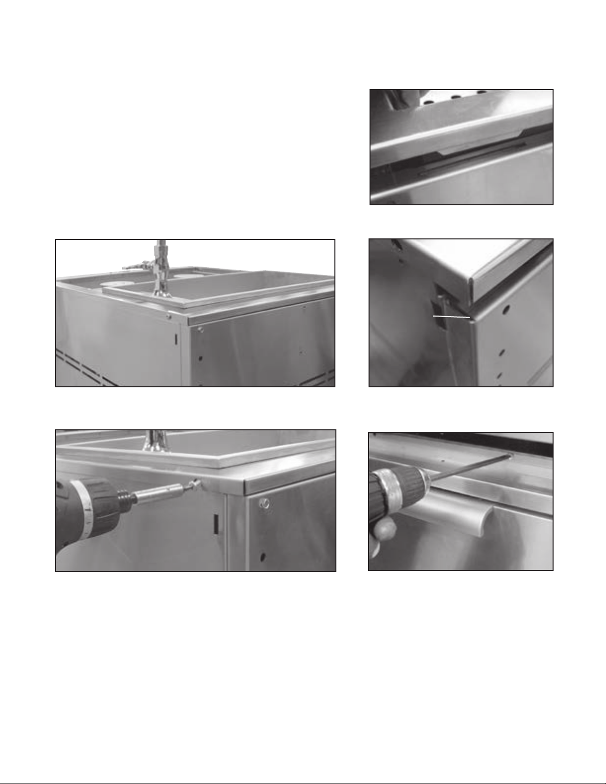
C. Position tabs on side bracket to fit into slots on the cart (be aware of
pinch points)(Fig. 44-45). When complete, the landing ledge should
sit flush on the top of the cart (no gap)(Fig. 46).
D. Secure the head to rear of cart (Fig. 47) with (2) Phillips-head screws
provided (10-24 x 1/2”).
E. Install remaining (3) screws (10-24 x 1/2”) into the front of head to
the cart (Fig. 48).
Fig. 45
PINCH POINT
Fig. 47
Fig. 44
Fig. 46
INSTALLATION
SINK DRAIN ASSEMBLY INSTRUCTIONS OPTIONAL
Loading ...
Loading ...
Loading ...