Loading ...
Loading ...
Loading ...

• 7 •
as a template, place the charger in the
selected location and mark each of
the four holes with a pencil. In a well
ventilated environment, drill the four holes
using a #9 (7/32˝) drill bit for use with nuts
and bolts OR with a 5/32˝ drill bit for use
with #10 self tapping screws. Use caution
when drilling, to avoid drilling into wires
or other components. Using #10 bolts,
nuts and lockwashers, mount the charger
with the LEDs facing up on a at vertical
surface, to allow for ventilation. Route the
AC and DC cords to either end and avoid
pinching them under the base. A sealant
may be used to waterproof the screw
holes.
8. DC WIRING DETAIL
When connecting the ring terminals to
the battery, remove nuts on battery posts,
place the ring terminal on corresponding
positive and negative post, and replace
each nut tightly to ensure a good
connection.
When connecting the ring terminals,
connect the black lead to the negative
battery post and the red lead to the
positive battery post.
When connecting the charger to TWO and
THREE batteries, connect the positive
lead from charging bank one to the
positive post of battery one. Connect the
negative lead from charging bank one to
the negative post of battery one. Connect
the leads from charging bank two to
battery two, and three to battery three in
the same fashion. NOTE: Removal of a
strap between two batteries in a 24- or
36-Volt system is not necessary.
1 battery 2 batteries 3 batteries
STRAP
OPTIONAL
STRAP
OPTIONAL
9. INLINE FUSES
Inline fuses, located close to the ends of
the red leads, protect the charger from
extremely high voltage surges, lightning
strikes or other high current surges. If a
fuse blows, replace only with an ATC-30
30A 32V blade fuse.
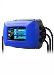
10. CONTROL PANEL
SELECT BUTTON –
Press to select battery type or check
battery type during charging.
LED INDICATORS
POWER ON (green):
The charger is connected to AC power.
CHARGING STATUS/
BATTERY TYPE (green) –
Charging status: After battery type has
been selected and charging has begun,
charging status is indicated from right to
left, in 25% increments. The LEDs will
blink and then turn solid, as charging
progresses.
The
LEDs of other banks
which are not charging will be solid on, to
show the percentage of those batteries.
100% 75% 50% 25%
STD AGM GEL OFF
Battery type:
To change the battery type, press and hold
the
Select button for 3 seconds, and
then toggle the button to select the desired
battery type. For a deep-cycle battery, refer
to the battery manufacturer’s specications
to determine the battery type. The LED will
Loading ...
Loading ...
Loading ...