Loading ...
Loading ...
Loading ...
4
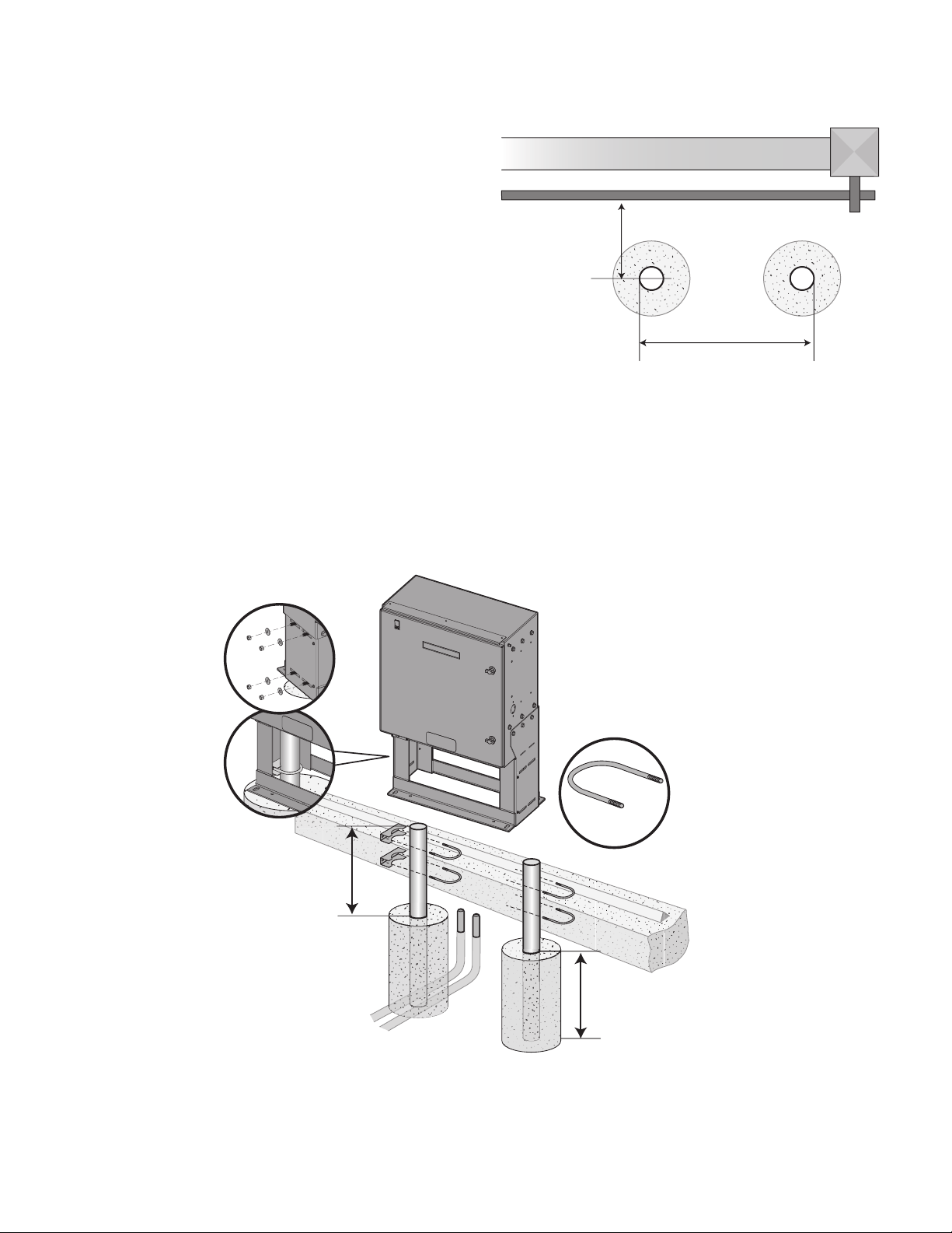
Post Mount (Option 2) Installation
The operators come from the factory configured to mount to an
inside theframe post mount dimension of 26" (66 cm) (outside to
outside ofposts). The frame comes slotted to accommodate posts
24-1/8" (61 cm) to 26" (66 cm), outside to outside.
NOTE: If you are replacing a SL580, the frame will require use of
supplied spacer bracket to accommodate 24 1/8" post spacing.
1. Locate and anchor two posts made of 3” (7.6cm) outer
diameter heavy walled pipe. Post should be parallel and square
to the gate.
2. Install the electrical conduit prior to pouring concrete.
3. Confirm that all power is disconnected from the operator.
4. Place Riser Stand in location of posts.
5. Secure Riser Stand to the posts using the supplied fasteners
and U-Bolts. Note that one set of the posts will mount on the
inside of the Riser Stand and the second set of posts will
mount outside of the Riser Stand outer plate.
6. Tighten riser stand to the posts, place the operator on top of
the riser stand.
7. Install the Mounting Bracket with supplied fasteners. Tighten to
30 lbs-ft. Check tightness of all mounting fasteners at least
once every 6 months. Tighten to recommended torque as
needed.
8. Once all attachments are complete, use cover plates to enclose
the riser stand.
LAYOUT OF POSTS (SL585, SL580 RETROFIT DESIGN)
3" (7.6 cm) U-bolts
(4 Required)
Depth Required By
Local Codes or Below
Frost Line
Power and Control Wiring Must
Be Run In Separate Conduit
14" (35.6 cm)
Minimum
Drive and idler sprocket
toward gate side
26" (66 cm)
(Gate)
3" (7.6 cm) outside diameter
heavy wall fence pipe
8.5" (21.6 cm)
© 2022 LiftMaster
All Rights Reserved
Tous droits réservés
114-5638-000 Todos los derechos reservados
Loading ...
Loading ...
Loading ...