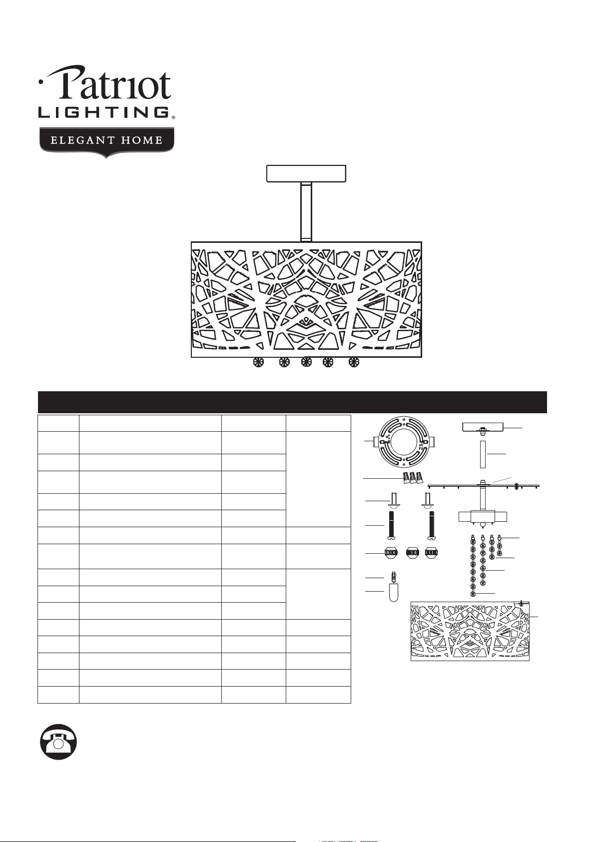
SKU NUMBER: 351-9121
5-LIGHT SEMI-FLUSH
MOUNT CEILING FIXTURE
MODEL NUMBER: MND3381A
Questions, problems, missing parts?
Before returning to your retailer, call our customer service at 1-800-645-3184,
Monday - , 7:00 a.m. -4:00 p.m., CST.Friday
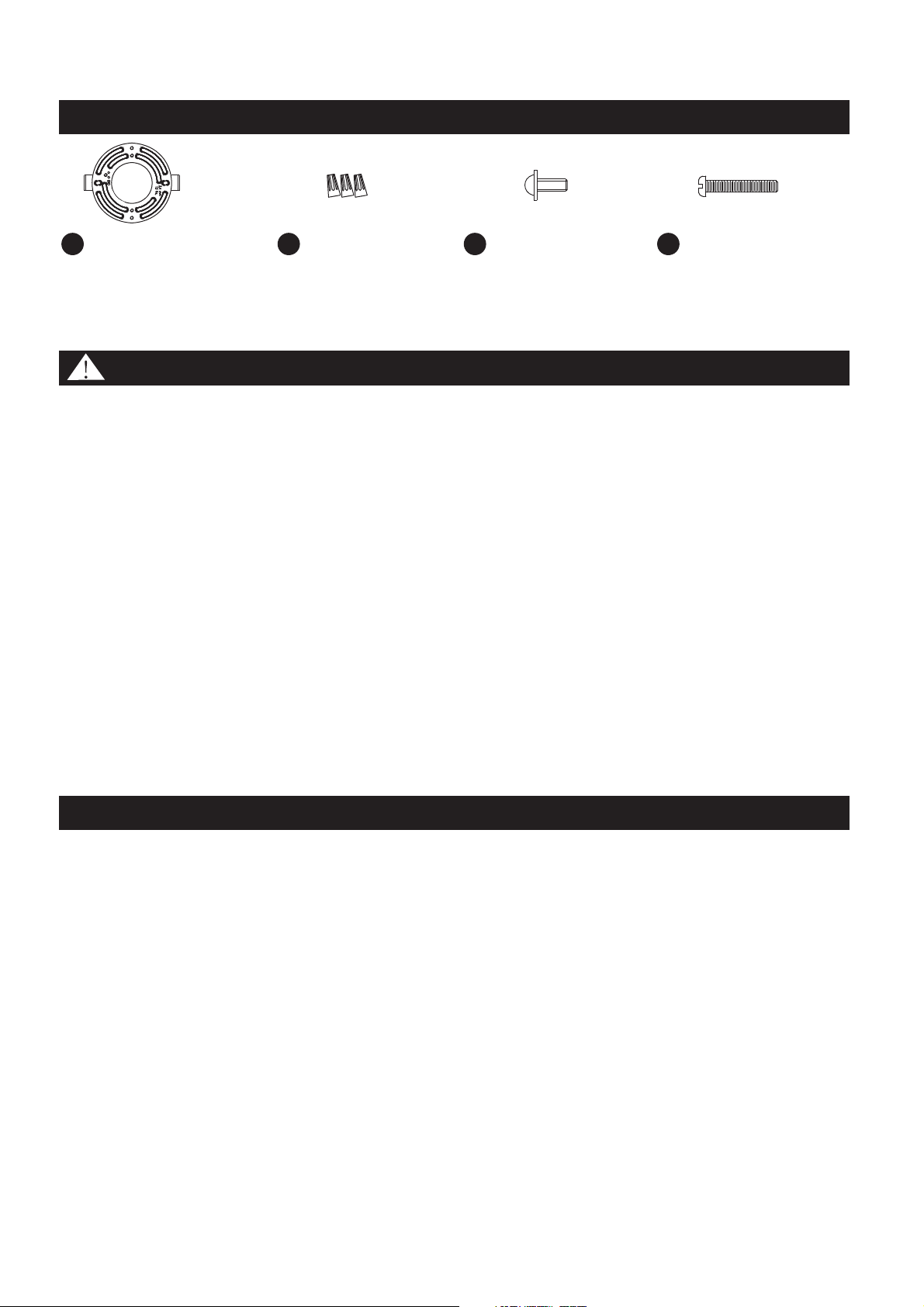
PACKAGE CONTENTS
1
REVISED 2017-05-27
B
PART
DESCRIPTION
QUANTITY
AA
Crossbar
(Pre-assembled to Fixture Body)
1pc
3pcs
2pcs
Wire Connector
Mounting Screw
(Pre-assembled to Fixture Body)
BB
CC
DD
Stock Part#
AA
BB
CC
DD
2pcs
Outlet Box Screw
C
A
B
C
D
E
F
G
H
I
J
K
A
3pcs
Lock Ball
Ceiling Canopy
D
1pc
E
1pc
Rod
Fixture Assembly
F
1pc
G
1pc
Crystal D
Crystal C
H
4pcs
I
37 pcs
Crystal A
Crystal B
J
10 pcs
Shade
K
1pc
Bulb Shield
(
For Halogen Bulb Only)
Bulb
5pcs
5pcs
I823SC
G13202BS
M13299SH
N/A
913449KIT
G12729CR
G12728CR
G12730CR
G12731CR
SAFETY INFORMATION
Please read and understand this entire manual before attempting to assemble, operate or install the
product.
● Turn off electricity at main fuse box (or circuit breaker box) before beginning installation by removing
fuse (or switching off circuit breaker).
Be careful not to damage or cut the wire insulation (covering) during fixture installation. Do not permit
wires to contact any surface having a sharp edge. To do so may damage or cut the wire insulation,
which could cause serious injury or death from electric shock
WARNING:
CAUTION:
●
● All electrical connections must be in agreement with local codes, ordinances or the National Electric
Code (NEC). Contact your municipal building department to learn about your local codes, permits
and/or inspections.
● Risk of fire – most dwellings built before 1985 have supply wire rated for 140°F/60ºC. Consult a
qualified electrician before installation.
● Do not connect this fixture to an electrical system that does not provide a means for equipment
grounding. Never use a fixture in a two-wire system that is not grounded. If you are not sure your
lighting system has a grounding means, do not attempt to install this fixture. Contact a qualified,
licensed electrician for information with regards to proper grounding methods as required by the local
electrical code in your area.
● If a dimmer control switch is used with this fixture, obtain professional advice to determine the correct
type and electrical rating required.
Before beginning assembly, installation or operation of product, make sure all parts are present. Compare
parts with package contents list and diagram on previous page. If any part is missing or damaged, do not
attempt to assemble, install or operate the product. Contact customer service for replacement parts
Tools Required for Assembly (not included):
Bulb Recommended: (5) 40W Clear G9 Halogen Bulbs, Alternate (5) LED bulb.
Flathead Screwdriver, Phillips Screwdriver, Electrical Tape,
Safety Goggles, Ladder.
PREPARATION
2
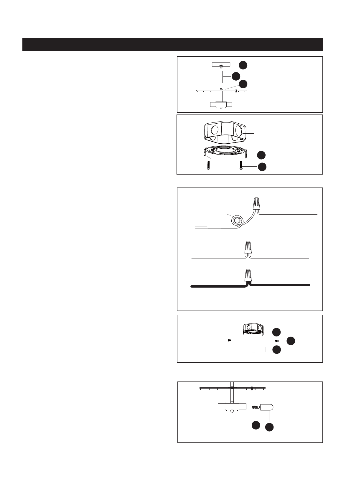
HARDWARE CONTENTS Note: Hardware not shown in actual size.
Crossbar
x1
Wire Connector
x3
Mounting Screw
x2
AA BB CC
Outlet Box Screw
x2
DD
ASSEMBLY INSTRUCTIONS
3
WHITE
BLACK (OR RED) WIRE
WHITE
BLACK
FROM SUPPLY
FROM SUPPLY
FROM FIXTURE
FROM FIXTURE
STEP 3:
* Use Wire Connectors (supplied) to connect the
wires.
a) Ground Wire:
1. Wrap supply around
on mounting bracket, no less than 2 inches
from the end of the wire. Tighten .
2. Connect fixture to
wire with wire connector.
b) Supply Wire:
1. Connect the to the
with wire connector.
2. Connect the wire to the
with wire connector.
3. Wrap each connection with approved electrical
tape and carefully stuff all of the connected wires
into the outlet box.
ground wire green ground
screw
ground screw
ground wire supply ground
supply white wire white
fixture supply wire
supply black (or red)
black fixture supply wire
GROUND WIRE
GROUND WIRE
FROM SUPPLY
FROM FIXTURE
GREEN GROUND SCREW
STEP 1:
a. Pass supply wires and ground wire through the
Rod (E) and the Ceiling Canopy (D).
b. Thread Rod (E) and the Ceiling Canopy
(D) to the fixture.
c. Hand tighten until snug.
D
E
F
AA
DD
Outlet Box
Tab
STEP 2:
a. Remove the crossbar (AA) from the ceiling
canopy on the fixture body.
b. Secure the crossbar to the outlet box (not
included) with outlet box screws (DD).
c. Tighten until snug.
The tab on the crossbar should protrude
outward.
Note:
STEP 4:
a. Fit excess wire and excess cable inside the outlet
box and inside of the fixture canopy.
b. Line up the holes on the Ceiling Canopy (D) and
the mounting holes on the Crossbar (AA).
c. Secure with the Mounting Screws (CC). Tighten
until snug.
CC
A
AA
STEP 5:
a. Insert bulbs (B) into fixture sockets.
b.
: Do not touch the bulb with bare
hands, as oil from your skin can damage the bulb;
use a soft cloth or gloves.
Cover with bulb shields (C) only if using
halogen bulbs. Hand tighten-until snug.
IMPORTANT
B
C
ASSEMBLY INSTRUCTIONS
4
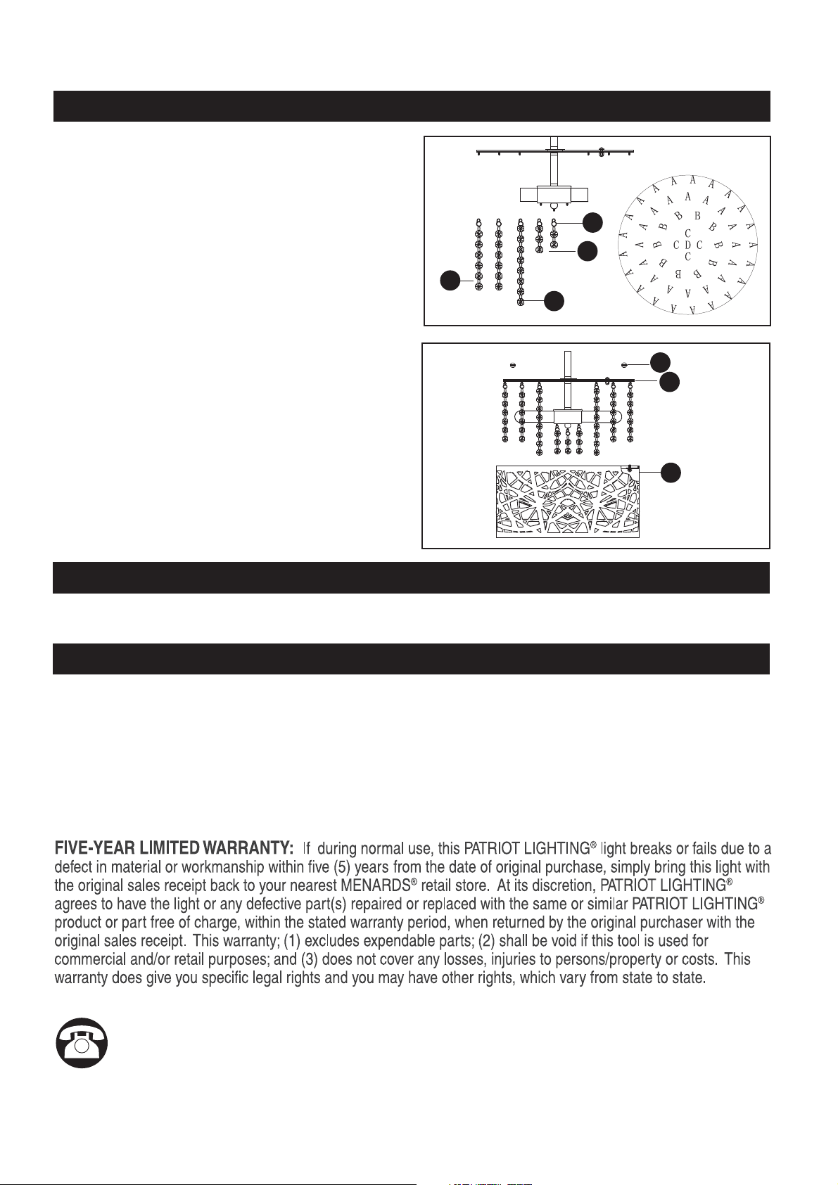
STEP 7:
a. Attach Shade (K) to Fixture Assembly (F) using
Lock balls (A).
b. Hand tighten until snug.
Your installation is now complete. Restore
electricity and retain this sheet for future
reference.
A
F
K
CARE AND MAINTENANCE
TROUBLESHOOTING
• To clean, turn off and wipe with a damp, non-abrasive cloth.
Questions, problems, missing parts?
Before returning to your retailer, call our customer service at 1-800-645-3184,
Monday - , 7:00 a.m. -4:00 p.m., CST.Friday
STEP 6:
A. Attach crystals (G) to the loops at location D.
b. Attach crystals (H) to the loops at location C.
c. Attach crystals (J) to the loops at location B.
d. Attach crystals (I) to the loops at location A.
G
H
J
I
Note: To prevent fingerprints and scratches on the
shade, put on gloves before installing the shade.
1) The light does not come on at all:
2) Fuse blows or circuit trips when light is turned on.
a) Make sure the wall switch and circuit breaker are on.
b) Make sure the wiring is correct.
a) Check for crossed wires. Ensure wiring is correct.
If unable to fix any of the above issues, please consult a certified electrician.