Loading ...
Loading ...

2. CONTENTS
- 3 -
- 10 -
Depending on manufacture and model, some engine components do change. Please check with
Autodata or the manufacturer’s data before use.
1. TITLE PAGE
1.1 INTRODUCTION.......................................................................................................... 2
1.2 REVISION HISTORY .................................................................................................. 2
1.3 UNDERSTANDING THIS GUIDE................................................................................. 2
1.4 COPYRIGHT NOTICE .................................................................................................2
2. CONTENTS
2.1 CONTENTS ....................................................................................................................3
3. GUARANTEE
3.1 GUARANTEE ............................................................................................................... 4
4. GENERAL PRODUCT INFORMATION
4.1 GENERAL PRODUCT INFORMATION ....................................................................... 5
5. HEALTH AND SAFETY INFORMATION
5.1 GENERAL SAFETY INSTRUCTIONS FOR USE
Personal safety........................................................................................................... 6
6. CONTENTS
6.1 PARTS DRAWING AND LISTING ............................................................................... 7
7. APPLICATION
7.1 PRODUCT APPLICATION AND COMPATIBILITY LISTING ...................................... 8
8. PREPARATION
8.1 ADVISORIES BEFORE USE ...................................................................................... 9
9. PROCEDURE AND APPLICATION GUIDE
9.1 APPLICATION GUIDANCE........................................................................................10
10. EXPLANATION OF SYMBOLS
10.1 EXPLANATION OF SYMBOLS .................................................................................. 11
9. PROCEDURE AND APPLICATION GUIDE
Please note images are for guidance only and subject to change.
Instructions for use:
• Always refer to manufacturer specific data and instructions.
• Gain access to the front of the engine requires removal of the right hand front wheel and
inner wheel arch and pipe work.
Components A: Exhaust Camshaft Holding Disc
Remove the cover plates from both camshafts and check the holes in the camshafts are
positioned as shown and fit component A as shown.
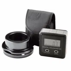
Component B Inclinometer Mounting Boss
Fit component B with the magnets facing the front crankshaft pulley and attach B with the flat
(F) facing down as shown.
Component C Inclinometer
Component c is used to digitally check the
number of degrees the crankshaft can be
turned with the exhaust cam shaft locked.
This figure indicates the amount the
chain has stretched. Using the magnets
in the base of the C attach it to the flat on
the mounting boss as shown.
NOTE: C will be upside down but will still
be easy to read.
Loading ...
Loading ...
Loading ...
