Loading ...
Loading ...
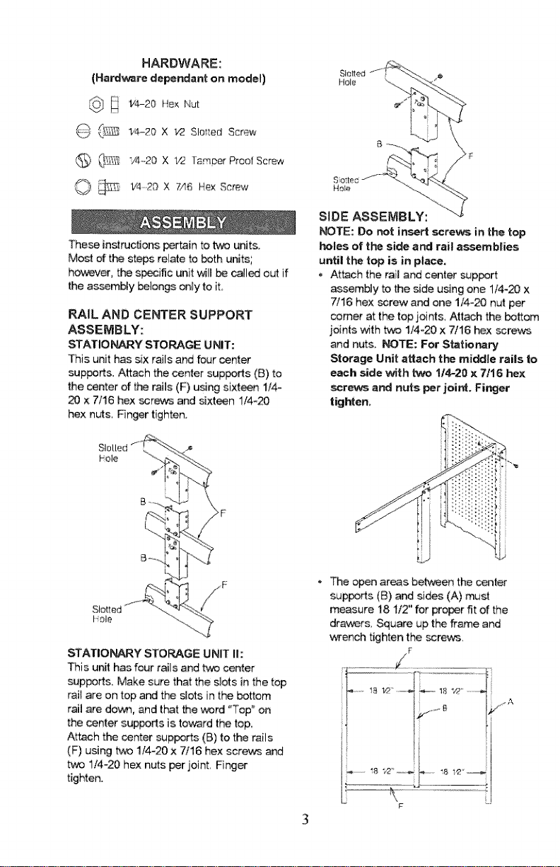
HARDWARE:
(Hard.re depe_ant on model)
_} _ 1'4-20 X t/2 Slei_ed Screw
6) @_,_ "/4_,20X V2 Tamper Proof Screw
O _ _,_2_x 7,,I_He×screw
These instructions pertain to two units.
Most of the steps relate to both units;
however, the specific unit will _ called out if
the assembly belongs only to iL
RAIL AND CENTER SUPPORT
ASSEMBLY:
STATIO_Y STORAGE UNIT:
This unit has six rails and four _nter
suppers. Attach the center supports (B) to
the center of the rails (F) using sixt_n 1/4-
20 x 7/16 hex screws and sixteen 1/4_20
hex nuts, Finger tighten.
SIo[[ed"f_''":_- ._
?;
21--_
Slot
bole
F
STATIONARY STORAGE UNIT I1:
This unit has four rails and tv_ center
supped& Make sure that the slots in the top
rail are on top and the slots in the bottom
rail are dove, and that the word "Top" on
the center supports is toward the top,
Attach the center supports (B) to the rails
(F) using two 1/4-20 x 7/16 hex screv_ and
t/4-20 hex nuts per joint Finger
tighten.
Slotted
iqole
Hole
SIDE ASSEMBLY:
_TE: Do not insert screws in the top
holes of t_ side and rail assemblies
until the top is in place.
- Attach the rail and center support
assembly to the side using one 1/4_20 x
7/16 hex screw and one 1/4-20 nut per
comer at the top joints, Attach the bottom
joints with two 1/4-20 x 7/16 hex ssrevcs
and nuts. _TE: For Stationary
Storage Unit attach the middle rails to
each side _th _ 1/4-20 x 7/16 hex
screws and nuts per joint, Finger
tighten.
The open areas between the center
supports (B) and sides (A) must
measure 18 1/2" for proper fit of the
drav,_rs, Square up the frame and
wench tighten the screws,
SLIDE ASSEMBLY:
NOTE: These units are designed so that
the drawers and shelves may be
positioned to suit your needs. During
installation of" the slides, start at either
the top or the bottom oftl_ unit a_
work to_rd the other end.
• Place the rear of the outside slide at the
rear of the unit, line up the holes and
attach the slide with tw'3 1/4-20 x 7/16
hex screws and _ 1/2=20 hex nuts,
Finger tighten, Attach the remaining
slides leaving a gap between them
according to the dra_r size.
- Before instaJling the inside slide, lubricate
the top and bottom channels of the
outside slide.
- Guide the inside slide into the channel at
the front end of the outside slide. R_ly
push the inside slide past the slide stop
on the outside slide. Repeat this step for
the remaining slides.
TOP ASSEMBLY:
• Place the top (H) on the rail and side
assembly; line up the four hobs and
attach the top using four 1/4-20 x 7/16
hex screws and 1/4-20 hex nuts.
i°
/! °
• Wrench tighten all screws and nu_s.
• Move the unit to a permanent location,
D_WER INSTALLATION:
Before instaJling the drawers, lubricate
the top and bottom channels of the
drawer slides,
. Install the drawer by in_rting the drawer
slides into the instalbd siide assemblbs
Make sure that the slides on both sides
line up, Push the drav_r until it is fully
close, The dra_,-_r is now securely in
place Repeat the procedure for the
remaining drawers.
NOTE: Door, lock, and door catch
a_mblies are for Stationary Storage
Unit II only.
DOOR ASSEMBLY:
NOTE: The door may be mounted on
either side of the unit, CAUTION: O_e
the door hinge screws are tightened
they cannot be removed with a
screwdriver.
o The door catch, lock, a_ mounting
hard.re is in a _parate bag,
• Remove the knockouts from the front
end panel on the side that the d_r is to
be hung,
Position the door on the side of the work
bench opening se!ected and line up the
holes on the hinge and the bench front,
3 4
Loading ...
Loading ...
Loading ...