Loading ...
Loading ...
TEFLON SEAL "-_
-/o ssL
HEX NUT
BRASS j
HEXBODY
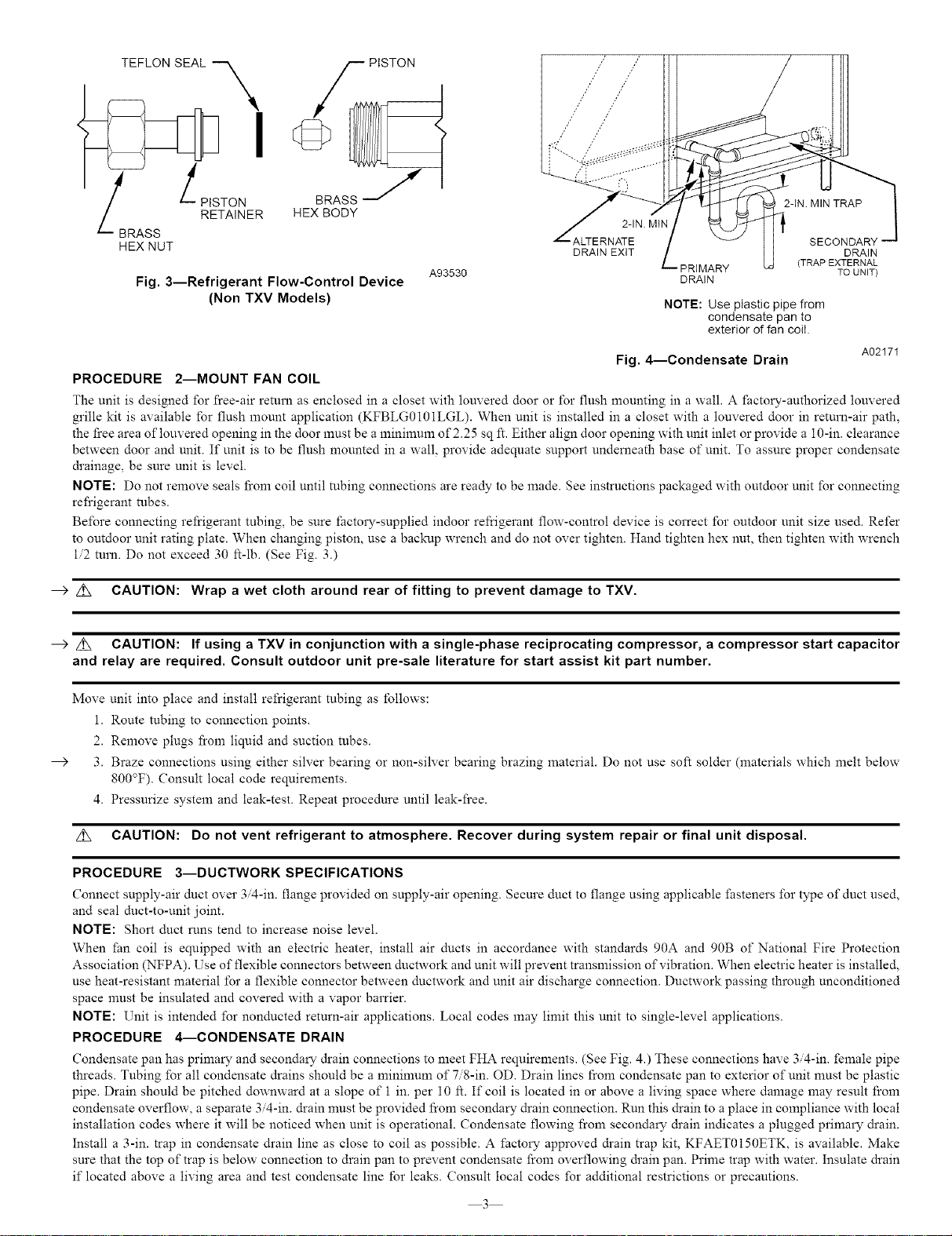
Fig. 3--Refrigerant Flow-Control Device
(Non TXV Models)
f_- ALTERNATE
DRAIN EXiT
PRIMARY
A93530 DRAIN
2-iN MIN TRAP
SECONDARk
DRAIN
(TRAP EXTERNAL
TO UNIT)
NOTE: Use plastic pipe from
condensate pan to
exterior of fan coil.
A02171
Fig. 4--Condensate Drain
PROCEDURE 2--MOUNT FAN COIL
The unit is designed for free-air return as enclosed in a closet with louvered door or for flush mounting in a wall. A factory-authorized louvered
grille kit is available for flush mount application (KFBLG0101LGL). When unit is installed in a closet with a louvered door in return-air path,
the free area of louvered opening in the door must be a minimum of 2.25 sq R. Either align door opening with unit inlet or provide a 10-in. clearance
between door and unit. If unit is to be flush mounted in a wall, provide adequate support underueath base of unit. To assure proper condensate
&ainage, be sure unit is level.
NOTE: Do not remove seals from coil until tubing connections are ready to be made. See instructions packaged with outdoor unit for connecting
refrigerant tubes.
Before connecting refrigerant tubing, be sure _actory-supplied indoor reliqgerant flow-control device is correct for outdoor unit size used. Refer
to outdoor unit rating plate. When changing piston, use a backup wrench and do not over tighten. Hand tighten hex nut, then tighten with wrench
i/2 turn. Do not exceed 30 It-lb. (See Fig. 3.)
--) z_ CAUTION: Wrap a wet cloth around rear of fitting to prevent damage to TXV.
--) z_ CAUTION: If using a TXV in conjunction with a single-phase reciprocating compressor, a compressor start capacitor
and relay are required. Consult outdoor unit pre-sale literature for start assist kit part number.
Move unit into place and install refrigerant tubing as tbllows:
1. Route tubing to connection points.
2. Remove plugs from liquid and suction tubes.
3. Braze connections using either silver bearing or non-silver bearing brazing material. Do not use soft solder (materials which melt below
800°F). Consult local code requirements.
4. Pressurize system and leak-test. Repeat procedure until leak-free.
Z_ CAUTION: Do not vent refrigerant to atmosphere. Recover during system repair or final unit disposal.
PROCEDURE 3--DUCTWORK SPECIFICATIONS
Connect supply-air duet over 3,4-in. flange provided on supply-air opening. Secure duct to flange using applicable fasteners for type of duct used,
and seal duct-to-unit joint.
NOTE: Short duct runs tend to increase noise level.
When _an coil is equipped with an electric heater, install air ducts in accordance with standards 90A and 90B of National Fire Protection
Association (NFPA). Use of flexible connectors between ductwork and unit will prevent transmission of vibration. When electric heater is installed,
use heat-resistant material for a flexible connector between ductwork and unit air discharge connection. Ductwork passing through unconditioned
space must be insulated and covered with a vapor barrier.
NOTE: Unit is intended for nonducted return-air applications. Local codes may limit this unit to single-level applications.
PROCEDURE 4---CONDENSATE DRAIN
Condensate pan has primary and secondary drain connections to meet FHA requirements. (See Fig. 4.) These connections have 3 4-in. female pipe
threads. Tubing for all condensate drains should be a minimum of 7/8-in. OD. Drain lines from condensate pan to exterior of unit must be plastic
pipe. Drain should be pitched downward at a slope of 1 in. per 10 ft. If coil is located in or above a living space where damage may result from
condensate overflow, a separate 3/4-in. &ain must be provided from secondary drain connection. Run this drain to a place in compliance with local
installation codes where it will be noticed when unit is operational. Condensate flowing from secondary &ain indicates a plugged primary drain.
Install a 3-in. trap in condensate drain line as close to coil as possible. A factory approved &ain trap kit, KFAET0150ETK, is available. Make
sure that the top of trap is below connection to drain pan to prevent condensate from overflowing &ain pan. Prime trap with water. Insulate drain
if located above a living area and test condensate line for leaks. Consult local codes for additional restrictions or precautions.
3
Loading ...
Loading ...
Loading ...