Loading ...
Loading ...
Loading ...
ELECTRICAL
NOTICE: Dual-voltage motors are factory wired for 230
volts. If necessary, reconnect the motor for 115 volts, as
shown. Do not alter the wiring in single voltage motors.
Install, ground, wire, and maintain your pump in compli-
ance with the National Electrical Code (NEC) or the
Canadian Electrical Code (CEC), as applicable, and with all
local codes and ordinances that apply. Consult your local
building inspector for code information.
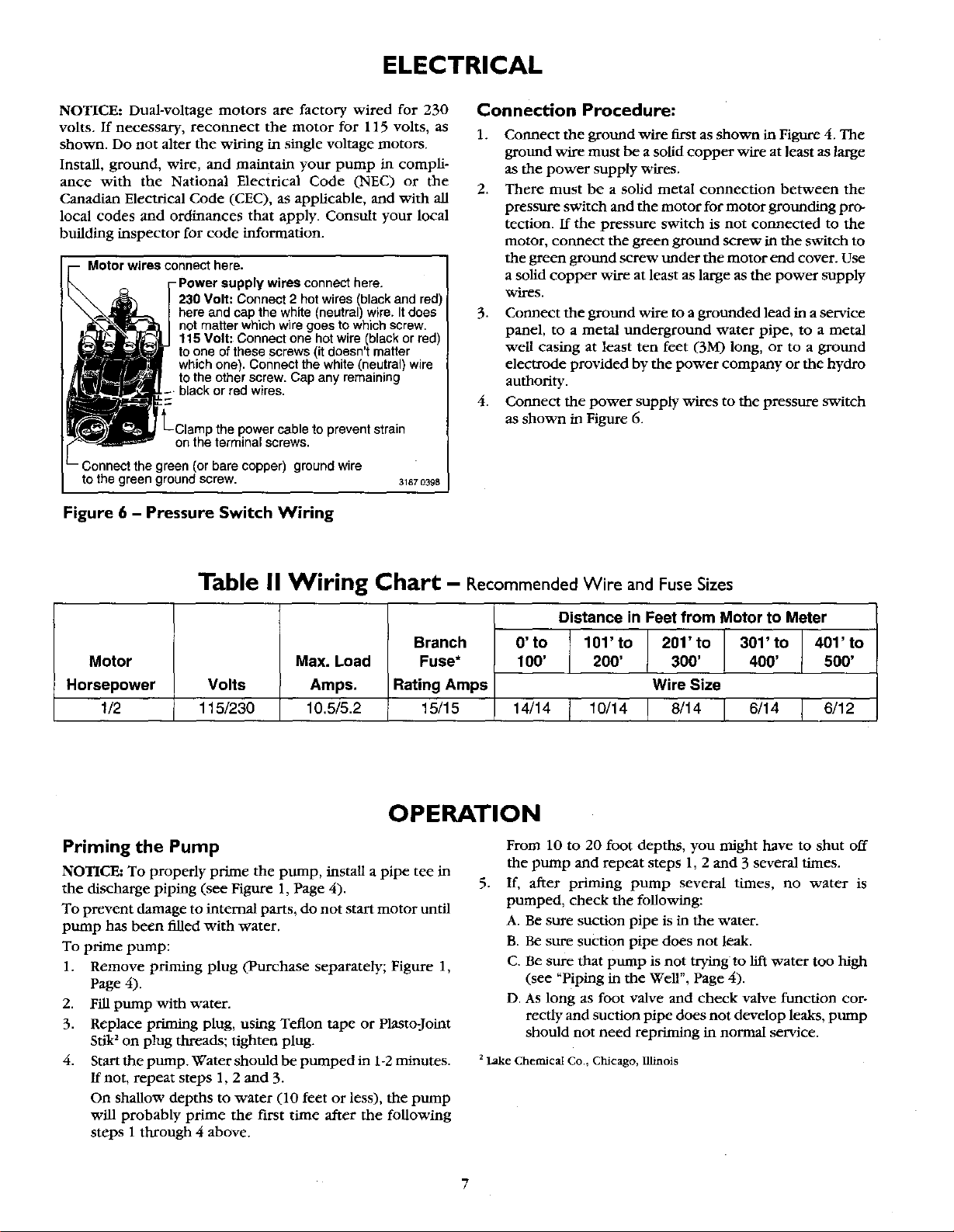
Motor wires connect here.
-Power supply wires connecthere.
230 Volt: Connect 2 hot wires(blackand red)
here and cap the white (neutral)wire. Itdoes
notmatter whichwire goes to whichscrew.
115 Volt: Connect one hotwire (blackorred)
toone of these screws(it doesn'tmatter
whichone). Connect the white(neutral)wire
tothe other screw. Cap any remaining
blackor red wires.
L;lampthe power cable to prevent strain
on the terminal screws.
- Connect the green (or bare copper) ground wire
to the green ground screw. 31870398
Figure 6 - Pressure Switch Wiring
Connection Procedure:
1.
2.
Connect the ground wire first as shown in Figure 4. The
ground wire must be a solid copper v_tre at least as large
as the power supply w'tres.
There must be a solid metal connection between the
pressure switch and the motor for motor grounding pro-
tection, ff the pressure switch is not connected to the
motor, connect the green ground screw in the switch to
the green ground screw tinder the motor end cover. Use
a solid copper wire at least as large as the power supply
wires.
3. Connect the ground wire to a grounded lead in a service
panel, to a metal underground water pipe, to a metal
well casing at least ten feet (3M) long, or to a ground
electrode provided by the power company or the hydro
authority.
4. Connect the power supply wires to the pressure switch
as shown in Figure 6.
Motor
Horsepower
1/2
Table II Wiring Chart - Recommended Wire and FuseSizes
Volts
115/230
Max. Load
Amps.
10.5/5.2
Branch
Fuse*
Rating Amps
15/15
Distance in Feet from Motor to Meter
0' to 101' to 201' to 301' to 401' to
100' 200' 300' 400' 500'
Wire Sizt
1_14 1_14 _14 _14 _12
OPERATION
Priming the Pump
NOTICE: To properly prime the pump, install a pipe tee in
the discharge piping (see Figure 1, Page 4).
To prevent damage to internal parts, do not start motor until
pump has been filled with water.
To prime pump:
1. Remove priming plug (Purchase separately; Figure 1,
Page 4).
2. Fill pump with water.
3. Replace priming plug, using Teflon tape or Plasto-Jcdmt
stik 2on plug threads; tighten plug.
4. Start the pump. Water should be pumped in 1-2 minutes.
ff not, repeat steps 1, 2 and 3.
On shallow depths to water (10 feet or less), the pump
will probably prime the first time after the following
steps 1 through 4 above.
5,
From 10 to 20 foot depths, you might have to shut off
the pump and repeat steps 1, 2 and 3 several times.
If, after priming pump several times, no water is
pumped, check the following:
A. Be sure suction pipe is in the water.
B. Be sure suction pipe does not leak.
C. Be sure that pump is not trying to llft water too high
(see "Piping in the Well", Page 4).
D. As long as foot valve and check valve function cor-
rectly and suction pipe does not develop leaks, pump
should not need repriming in normal service.
z Lake Chemical Co., Chicago, Illinois
Loading ...
Loading ...
Loading ...