31-49144 08-17 GEA
Installation
Instructions
Bracket Mount Instructions
WR30X10061 & WR30X10062
Questions? Call 1-800-GE-CARES (1-800-432-2737)
STATE OF CALIFORNIA PROPOSITION 65 WARNINGS
WARNING
This product contains one or more chemicals known to the State of California to cause
cancer and birth defects or other reproductive harm.
WARNING
To reduce the risk of fire, explosion, electric shock, or injury when using your refrigerator,
follow these basic safety precautions:
Ŷ5HDGWKHIXOO6DIHW\,QIRUPDWLRQDQG,QVWUXFWLRQV
of your refrigerator before installing or operating
the icemaker.
Ŷ8QSOXJWKHUHIULJHUDWRUEHIRUHEHJLQQLQJWKH
installation of this icemaker accessory kit.
Ŷ:KHQPRYLQJWKHUHIULJHUDWRUDZD\IURPWKHZDOO
be careful not to roll over or damage the power
cord.
Ŷ5HSODFHDOOSDUWVDQGSDQHOVRIWKHUHIULJHUDWRU
before operating.
Ŷ&RQQHFWWRSRWDEOHZDWHUVXSSO\RQO\
CAUTION
Avoid contact with the moving parts of the icemaker ejector mechanism, or with the heating element that
releases the cubes, located on the bottom of the icemaker. Do not place fingers or hands on the automatic
icemaker while the refrigerator is plugged in.
IMPORTANT SAFETY INFORMATION
READ ALL INSTRUCTIONS BEFORE INSTALLING THE ICEMAKER OR ACCESSORIES
Tools Needed
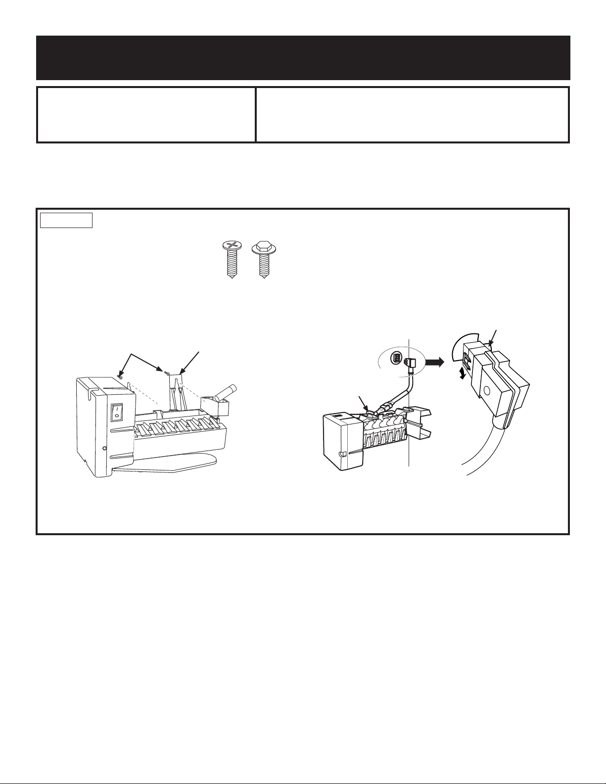
Flatblade screwdriver Phillips head screwdriver 1/4" Hex head driver
2
31-49144
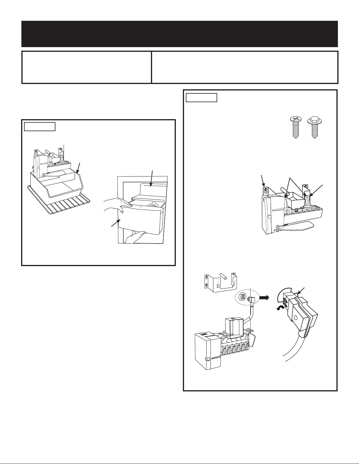
STEP 2 REMOVE THE EXISTING
ICEMAKER
The icemaker will be attached to the
icemaker bracket with a Phillips head
or Hex head screws.
Ŷ 8VLQJWKHDSSURSULDWHVFUHZGULYHU
loosen the 2 mounting screws
until the screw heads extend
about 1/2" (13mm) from the
icemaker bracket.
NOTE: Do not
completely remove
the screws.
Ŷ 6OLGHWKHLFHPDNHU
upwards so that the
screws are in the wide
part of the mounting
tab. Pull the icemaker
away from the
icemaker bracket.
Ŷ 7RXQSOXJWKH
icemaker, locate the restraints on each side of the
SOXJ8QFOLSWKHUHVWUDLQWVE\SXOOLQJRXWZDUG
Ŷ 8QSOXJWKHLFHPDNHUIURPWKHVRFNHWORFDWHGRQWKH
rear wall of the freezer.
Dispenser
Side-By-Side Bucket
Installation
Instructions
Bracket Mount Instructions
WR30X10061 & WR30X10062
STEP 1 REMOVE THE ICE BUCKET &
CHILLER SHELF
,I$SSOLFDEOH
USE THESE INSTRUCTIONS FOR METAL INTERIOR LINED
SIDE-BY-SIDE REFRIGERATORS ONLY
These instructions apply to metal interior lined side-by-
side refrigerators only. For Plastic interior lined side-
by-side refrigerators refer to page 4. For top-freezer
refrigerators refer to page 6.
ON–
O
FF
,FH%XFNHW
,FH%XFNHW
Non-Dispenser
Side-By-Side Bucket
Chiller Shelf
Phillips Hex
Head Head
(Appearance may vary)
ON–OFF
,FHPDNHU
Bracket
Mounting
Screws
Mounting
Tabs
8QFOLS5HVWUDLQWV
by Pulling Them
Outward
0D\5HTXLUH
a Flatblade
Screwdriver to
8QFOLS5HVWUDLQWV
on Back Side
3
31-49144
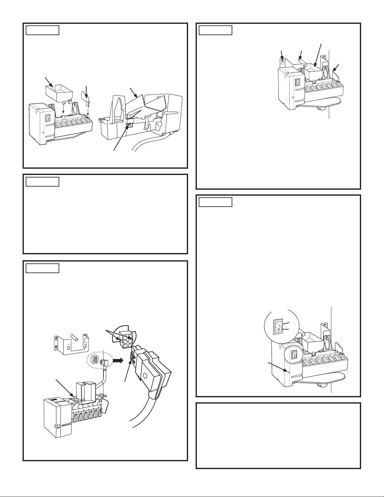
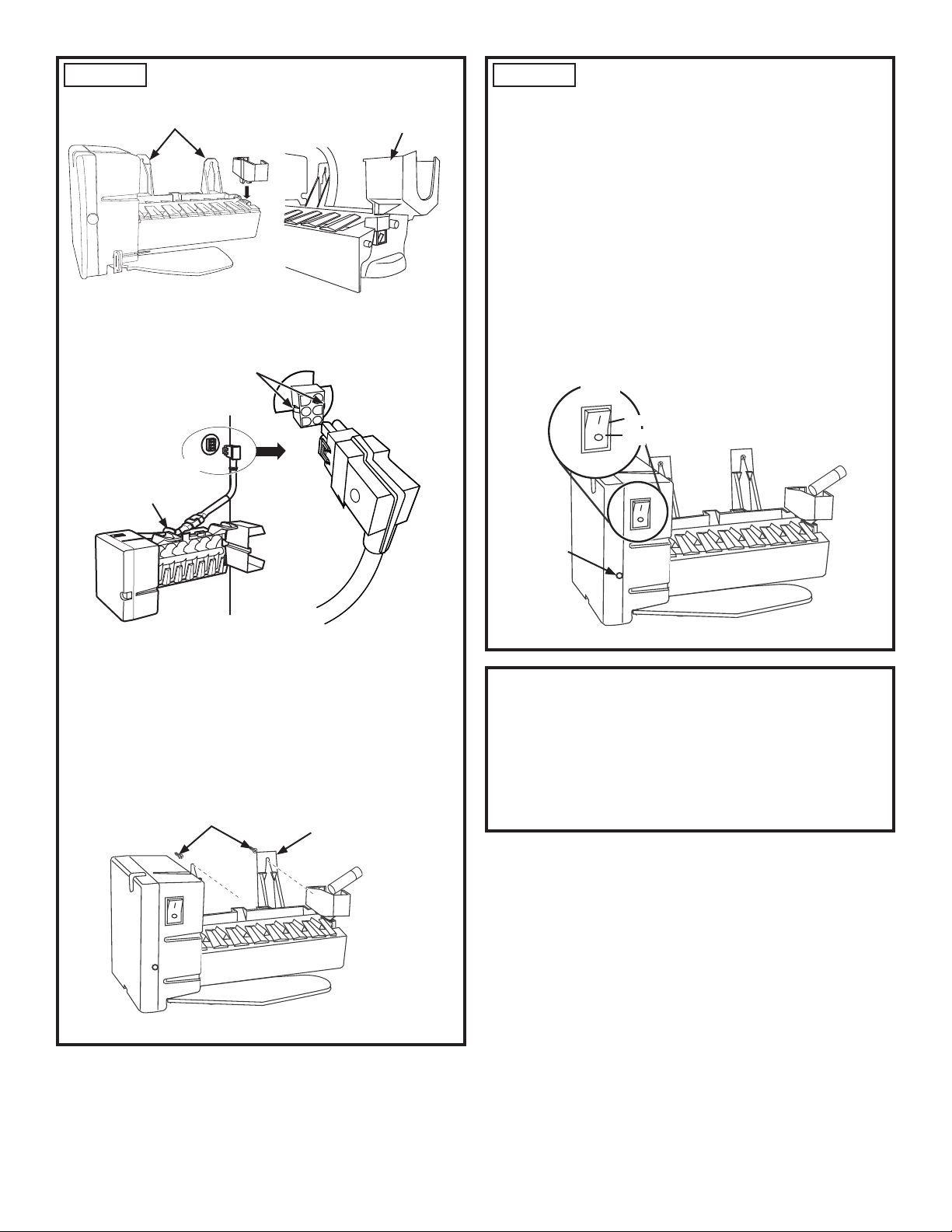
STEP 3 REMOVE FILL CUP AND
ICEMAKER INSERT
Ŷ 5HPRYHWKH¿OOFXSDQGLFHPDNHULQVHUWIURPWKHROG
icemaker.
Ŷ 'LVFDUGWKHROGLFHPDNHU
STEP 6 MOUNT THE ICEMAKER
Ŷ /LIWWKHLFHPDNHUXS
and hang it on the
icemaker bracket.
0DNHVXUHWKH¿OO
WXEHJRHVLQWRWKH¿OO
cup opening. Secure
the icemaker to the
bracket with the two
screws and install as
shown.
NOTE:,WLVFULWLFDOWKDW
WKH¿OOWXEHLVSRVLWLRQHG
LQWRWKH¿OOFXSRSHQLQJ
Make Sure:
Ŷ 7KHSRZHUFRUGLVVWLOO¿UPO\LQWKHVRFNHW
Ŷ 7KH¿OOWXEHH[WHQGVLQWRWKH¿OOFXSRSHQLQJDWWKH
back of the icemaker.
Ŷ 7KHLFHPDNHULVVHFXUHGWRWKHEUDFNHW
Ŷ 7KHLFHPDNHULVOHYHOVLGHWRVLGHDQGIURQWWREDFN
STEP 7 COMPLETE THE
INSTALLATION
Ŷ 5HFRQQHFWSRZHUWRWKHUHIULJHUDWRU
Ŷ 6HWWKHLFHPDNHUSRZHUVZLWFKWRWKH21SRVLWLRQ
Ŷ &KHFNWRPDNHFHUWDLQWKHJUHHQSRZHULQGLFDWRUOLJKW
LVRQ,IWKHJUHHQLQGLFDWRUOLJKWGRHVQRWWXUQRQ
- Check to be certain that the icemaker power cord is
plugged in correctly.
- Check to see if the icemaker power switch is in the
ON position.
- Check to be certain that the refrigerator is plugged in.
Ŷ 5HSODFHWKHLFHEXFNHWDQGFKLOOHUVKHOILIDSSOLFDEOH
5HWXUQDQ\LWHPVWKDWZHUHUHPRYHGWRWKHIUHH]HU
It may take
several hours
for the freezer
to reach the
selected
temperature
and for ice
production to
begin.
Congratulations! You have completed the installation of
\RXUQHZ*($SSOLDQFHVHOHFWURQLFLFHPDNHU,I\RXKDYH
any further issues with the icemaker or your refrigerator,
please call 1-800-GE-CARES (1-800-432-2737) for
additional help or information.
Thank you for choosing GE Appliances.
STEP 5 PLUG IN THE ICEMAKER
Holding the icemaker in place, insert the icemaker power
cord plug into the socket, making sure that the prongs
and holes are matched. Press the plug firmly into the
VRFNHW/RFNWKHSOXJLQSODFHE\FOLSSLQJWKHUHVWUDLQWV
onto each side of the plug. Make sure the restraints click
into place.
NOTE:7KHSRZHUFRUG6+28/'127EHSODFHGLQWKH
hook on the back of the icemaker.
STEP 4 INSTALL FILL CUP AND
ICEMAKER INSERT INTO NEW
ICEMAKER
Ŷ ,I\RXUHFHLYHGD1(:¿OOFXSZLWK\RXULFHPDNHU
LQVWDOOWKH¿OOFXSQRZ
Ŷ ,I\RXGLGQRWUHFHLYHDQHZ¿OOFXSUHLQVWDOOWKH¿OO
cup from the old icemaker.
Ŷ ,QVWDOOWKHLFHPDNHULQVHUWLQWRWKHQHZLFHPDNHU
Fill Cup
Fill Cup
,FHPDNHU
,QVHUW
3UHVV7DE,Q
DQG3XOO8S
Hook
&OLS5HVWUDLQWV
RQWR/RFNLQJ
Tabs
/RFNLQJ7DEV
,FHPDNHU
Bracket
Mounting
Tabs
Fill Cup
Fill Tube
(Appearance may vary)
Power
Switch
On
2ႇ
Power
,QGLFDWRU
/LJKW

4
31-49144
Installation
Instructions
Bracket Mount Instructions
WR30X10061 & WR30X10062
STEP 1 REMOVE THE ICE BUCKET
STEP 2 REMOVE THE EXISTING
ICEMAKER
The icemaker will be attached to the
icemaker bracket with Phillips head
or Hex head screws.
Ŷ 8VLQJWKHDSSURSULDWHVFUHZGULYHU
loosen and remove the 2
mounting screws.
NOTE: Remove screws
completely. ,IVFUHZVIDOOLQWRWKHLFHPDNHUWKH\FDQ
be retrieved when icemaker has been removed.
Ŷ 6OLGHWKHLFHPDNHUXSDQGRXWIURPWKHEUDFNHW
Ŷ 7RXQSOXJLFHPDNHUORFDWHUHVWUDLQWVRQHDFKVLGHRI
SOXJ8QFOLSWKHUHVWUDLQWVE\SXOOLQJRXWZDUG
Ŷ 8QSOXJLFHPDNHU
from socket
located on the
top of auger
motor housing.
STEP 3 REMOVE FILL CUP, ICEMAKER
INSERT AND PLASTIC STRIPPER PLATE
Ŷ 5HPRYH¿OOFXSDQGLFHPDNHULQVHUWIURPROGLFHPDNHU
Ŷ <2808675(029(7+(2/'675,33(5$1'
86(217+(1(:,&(0$.(5<28&$112786(
7+(1(:675,33(5
To remove, gently pull out on the center of the plastic
to disengage the right end from the slot on the
KRXVLQJ3XVKWKHSLHFHRႇWKHPROGERG\SRVWDWWKH
opposite end. You may need to wiggle the stripper.
5HPRYHWKHVWULSSHUIURPWKHQHZLFHPDNHUWKHVDPH
way, and replace with the original one.
Ŷ 'LVFDUGWKHROGLFHPDNHU
USE THESE INSTRUCTIONS FOR PLASTIC INTERIOR LINED
SIDE-BY-SIDE REFRIGERATORS ONLY
These instructions apply to plastic interior lined side-
by-side refrigerators only. For Metal interior lined side-
by-side units refer to page 2. For top-freezer units refer
to page 6.
Ice Bucket
Phillips Hex
Head Head
ON–OFF
,FHPDNHU
Bracket
Mounting
Screws
8QFOLS5HVWUDLQWV
by Pulling Them
Outward
0D\5HTXLUH
a Flatblade
Screwdriver
WR8QFOLS
5HVWUDLQWVRQ
Back Side
Fill Cup
,FHPDNHU
,QVHUW
Fill Cup
3UHVV7DE,Q
DQG3XOO8S
Stripper Plate
Stripper Plate
Mold Body
STEP 4 INSTALL FILL CUP AND
ICEMAKER INSERT INTO NEW
ICEMAKER
Ŷ ,I\RXUHFHLYHGD1(:¿OOFXSZLWK\RXULFHPDNHU
LQVWDOOWKH¿OOFXSQRZ
Ŷ ,I\RXGLGQRWUHFHLYHDQHZ¿OOFXSUHLQVWDOOWKH¿OO
cup from the old icemaker.
Ŷ ,QVWDOOWKHLFHPDNHULQVHUWLQWRWKHQHZLFHPDNHU
5
31-49144
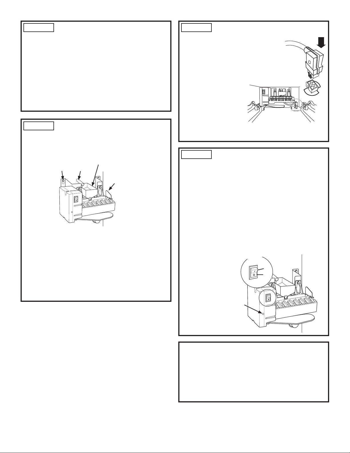
STEP 5 ATTACH THE ORIGINAL
PLASTIC STRIPPER PLATE TO NEW
ICEMAKER
Ŷ $OLJQWKHKROHRQWKHRULJLQDOSODVWLFVWULSSHUZLWKWKH
SRVWRQWKHHQGRIWKHLFHPDNHU5RWDWHWKHSLHFH
towards mold body as you pull it onto the post.
Ŷ )OH[WKHSODVWLFRXWZDUGIURPWKHPLGGOHDV\RXDOLJQ
the end with the slot in the housing.
Ŷ 0DNHFHUWDLQWKHJURRYHVRQWKHLQVLGHRIWKHVWULSSHU
DOLJQZLWKWKHPROGERG\VRWKDWLW¿WVVWUDLJKW
STEP 6 MOUNT THE ICEMAKER
Ŷ /LIWWKHLFHPDNHUXSDQGKDQJLWRQWKHLFHPDNHU
EUDFNHW0DNHVXUHWKH¿OOWXEHJRHVLQWRWKH¿OOFXS
opening. Secure the icemaker to the bracket with the
two screws and install as shown.
NOTE:,WLVFULWLFDOWKDWWKH¿OOWXEHLVSRVLWLRQHGLQWRWKH
¿OOFXSRSHQLQJ
Make Sure:
Ŷ 7KH¿OOWXEHH[WHQGVLQWRWKH¿OOFXSRSHQLQJDWWKH
back of the icemaker.
Ŷ 7KHLFHPDNHULVVHFXUHGWRWKHEUDFNHW
Ŷ 7KHLFHPDNHULVOHYHOVLGHWRVLGHDQGIURQWWREDFN
,FHPDNHU
Bracket
Mounting
Tabs
Fill Cup
Fill Tube
(Appearance may vary)
STEP 7 PLUG IN THE ICEMAKER
,QVHUWWKHLFHPDNHU
power cord plug into the
socket, making sure that
the prongs and holes are
matched. Press the plug
firmly into the socket.
/RFNWKHSOXJLQSODFH
by clipping the restraints
onto each side of the
plug. Make sure the
restraints click into place
and the power cord is
firmly in the socket.
NOTE:7KHSRZHUFRUG6+28/'EHSODFHGLQWKHKRRN
on the back of the icemaker.
STEP 8 COMPLETE THE
INSTALLATION
Ŷ 5HFRQQHFWSRZHUWRWKHUHIULJHUDWRU
Ŷ 6HWWKHLFHPDNHUSRZHUVZLWFKWRWKH21SRVLWLRQ
Ŷ &KHFNWRPDNHFHUWDLQWKHJUHHQSRZHULQGLFDWRUOLJKW
LVRQ,IWKHJUHHQLQGLFDWRUOLJKWGRHVQRWWXUQRQ
- Check to be certain that the icemaker power cord is
plugged in correctly.
- Check to see if the icemaker power switch is in the
ON position.
- Check to be certain that the refrigerator is plugged in.
Ŷ 5HSODFHWKHLFHEXFNHWDQGFKLOOHUVKHOILIDSSOLFDEOH
5HWXUQDQ\LWHPVWKDWZHUHUHPRYHGWRWKHIUHH]HU
It may take
several hours
for the freezer
to reach the
selected
temperature
and for ice
production to
begin.
Congratulations! You have completed the installation of
\RXUQHZ*($SSOLDQFHVHOHFWURQLFLFHPDNHU,I\RXKDYH
any further issues with the icemaker or your refrigerator,
please call 1-800-GE-CARES (1-800-432-2737) for
additional help or information.
Thank you for choosing GE Appliances.
Power
Switch
On
2ႇ
Power
,QGLFDWRU
/LJKW
6
31-49144
STEP 1 REMOVE THE EXISTING ICEMAKER
The icemaker will be attached to the
side wall of the freezer with a Phillips
head or Hex head screws.
Ŷ 8VLQJWKHDSSURSULDWHVFUHZGULYHU
loosen the mounting screws until
the screw heads extend about 1/2"
(13mm) from the freezer wall.
NOTE: Do not completely remove the screws.
Ŷ 6OLGHWKHLFHPDNHUXSZDUGVVRWKDWWKHVFUHZVDUHLQ
the wide part of the mounting tab. Pull the icemaker
away from the side wall of the freezer.
Ŷ 7RXQSOXJWKHLFHPDNHUORFDWHWKHUHVWUDLQWVRQ
HDFKVLGHRIWKHSOXJ8QFOLSWKHUHVWUDLQWVE\SXOOLQJ
outward.
Ŷ 8QSOXJWKHLFHPDNHUIURPWKHVRFNHWORFDWHGRQWKH
back or side wall of the freezer.
Ŷ 'LVFDUGROGLFHPDNHU
Installation
Instructions
Bracket Mount Instructions
WR30X10061 & WR30X10062
USE THESE INSTRUCTIONS FOR TOP-FREEZER
REFRIGERATORS ONLY
These instructions apply to top-freezer refrigerators
only. For metal interior lined side-by-side refrigerators
refer to page 2. For plastic interior lined side-by-side
refrigerators refer to page 4.
Phillips Hex
Head Head
Mounting
Screws
Mounting
Tabs
0D\5HTXLUHD)ODWEODGH
6FUHZGULYHUWR8QFOLS
5HVWUDLQWVRQ%DFN6LGH
8QFOLS
5HVWUDLQWVE\
Pulling Them
Outward
Hook
8QSOXJ
7
31-49144
STEP 2 INSTALL THE NEW ICEMAKER
Ŷ $VVHPEOHWKH¿OOFXSWRWKHLFHPDNHU
Ŷ 3OXJWKHLFHPDNHUSRZHUFRUGLQWRWKHVRFNHW3UHVV
¿UPO\LQWRSODFH/RFNWKHSOXJLQSODFHE\FOLSSLQJWKH
restraints onto each side of the plug.
NOTE: If the plug is located on the back wall of the
freezer, the power cord SHOULD NOT be placed in
the hook on the back of the icemaker.
Ŷ 3RVLWLRQWKHLFHPDNHUPRXQWLQJWDEVRYHUWKH
mounting screws. NOTE: ,WLVFULWLFDOWKDWWKH¿OOWXEH
LVSRVLWLRQHGLQWKH¿OOFXSRSHQLQJ
Ŷ 5HWLJKWHQWKHPRXQWLQJVFUHZV0DNHFHUWDLQWKDWWKH
icemaker is level.
STEP 3 COMPLETE THE INSTALLATION
Ŷ 5HFRQQHFWSRZHUWRWKHUHIULJHUDWRU
Ŷ 6HWWKHLFHPDNHUSRZHUVZLWFKWRWKH21SRVLWLRQ
Ŷ &KHFNWRPDNHFHUWDLQWKHJUHHQSRZHULQGLFDWRUOLJKW
LVRQ,IWKHJUHHQLQGLFDWRUOLJKWGRHVQRWWXUQRQ
- Check to be certain that the icemaker power cord is
plugged in correctly.
- Check to see if the icemaker power switch is in the
ON position.
- Check to be certain that the refrigerator is plugged in.
Ŷ 5HSODFHWKHLFHEXFNHWLQWKHSURSHUORFDWLRQ5HWXUQ
any items that were previously removed from the
freezer.
,WPD\WDNHVHYHUDOKRXUVIRUWKHIUHH]HUWRUHDFKWKH
selected temperature and for ice production to begin.
ON–
OFF
Mounting Tabs
Fill Cup
Hook
/RFNLQJ7DEV
Clip
5HVWUDLQWV
RQWR/RFNLQJ
Tabs
3OXJ,Q
Mounting Screws
Mounting Tabs
Fill Tube
Fill Cup
Congratulations! You have completed the installation of
\RXUQHZ*($SSOLDQFHVHOHFWURQLFLFHPDNHU,I\RXKDYH
any further issues with the icemaker or your refrigerator,
please call 1-800-GE-CARES (1-800-432-2737) for
additional help or information.
Thank you for choosing GE Appliances.
Power
Switch
On
2ႇ
Power
,QGLFDWRU
/LJKW

8
31-49144
Notes