Loading ...
Loading ...
Loading ...
13
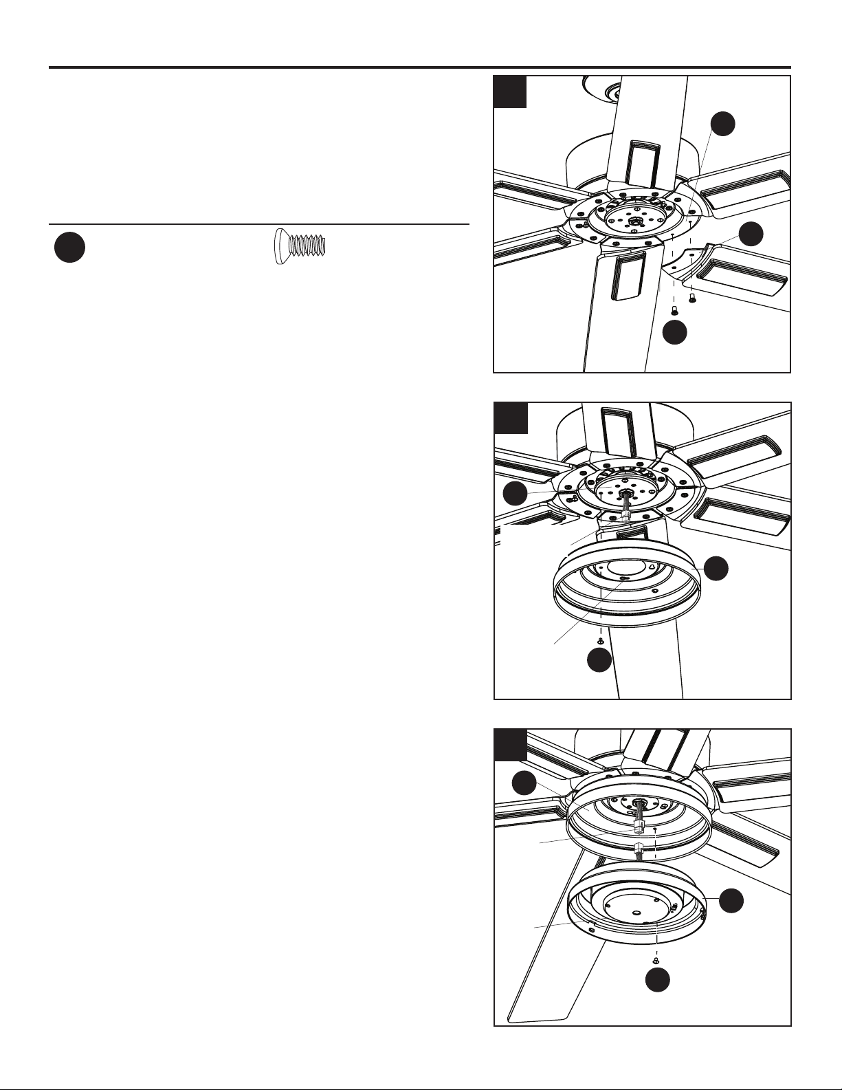
FINAL INSTALLATION
4. Insert blade arm (S) through slot in the side of the
motor assembly (H). Align the holes of one blade arm
(S) with two motor screw holes in underside of the
motor assembly (H). Secure with two motor screws
(XX). Repeat this step for the remaining blade arms
(S).
Hardware Used
XX
Motor Screw x 12
5. Remove one and loosen the other three tter plate
screws (L) but do not remove from tter plate (K).
Feed the 6-pin connector through center hole in light
pan (M). Align the three keyhole slots in the light pan
(M) with the loosened tter plate screws (L). Place the
light pan (M) over the three screws and turn the light
pan (M) clockwise. Then tighten the three tter plate
screws (L). Re-install the tter plate screw (L) that
was removed in the previous step and tighten rmly.
6. Remove one and loosen the other two light pan
screws (N) from the underside of the light pan (M).
Connect the 6-pin connector from the tter plate (K)
to the 6-pin connector from the light kit (O). Align the
keyhole slots in the light kit (O) with the loosened
screws in the light pan (M). Turn light kit (O) clockwise
and replace the previously removed light pan screw
(N). Tighten all screws.
4
H
O
N
M
L
M
K
S
XX
5
6
6-pin
Connector
6-pin
Connector
Keyhole
Slot
Keyhole
Slot
Loading ...
Loading ...
Loading ...