Loading ...
Loading ...
Loading ...
7
Preparing for Installation
WARNING
• If the gas or electric service provided does not meet the
product specifications, do not proceed with the installation.
Call the dealer, the gas supplier or a licensed electrician.
• Before installing the range, you must locate and secure the
anti-tip bracket to the floor.
IMPORTANT: Within the Commonwealth of Massachusetts, this
appliance must be installed by a licensed plumber or gas fitter.
Unpacking the Range
Unpack the parts box and verify that all required components
have been provided. If any item is missing or damaged, please
contact your dealer immediately. Do not install a damaged or
incomplete appliance.
Installation Instructions
Parts List
- Grates (2)
- Standard burner caps
(3 brass, 3 porcelain)*
- Standard burner rings (3)
- SimmerSear burner caps
(1 brass, 1 porcelain)*
- SimmerSear burner ring (1)
- SimmerSear burner head (1)
- GlideRack™ oven racks (2)
- Standard rack (1)
- 5 Knobs (2 MAX GRIDDLE,
2 Standard, 1 Oven)
- Anti-tip bracket with screws
and anchors
- Griddle (1)
- Wok ring (1)
- Broiler pan/grill (1)
- Stainless steel cleaner (1)
- Literature kit (1)
*The range is supplied with two different styles of burner caps
(brass and porcelain) to suit the customer’s preference. Please
note that because the burner caps are made of brass, heat will
distort the brass’ color over time.
Replacing the Backguard
If a different backguard will be used, please assemble it before
pushing the range into position.
Model Number Item
APB30GLP 1.5-inch high Backguard (Low Profile)
APB30D9 9-inch high Backguard
Downdraft Installation
If installing a downdraft, install it before moving the range into
position.
An additional trim kit must be used to unify the downdraft, range,
and backguard into one piece.
Model Number Item
ERV3015 Downdraft
ATKERV-RP30 Trim Kit
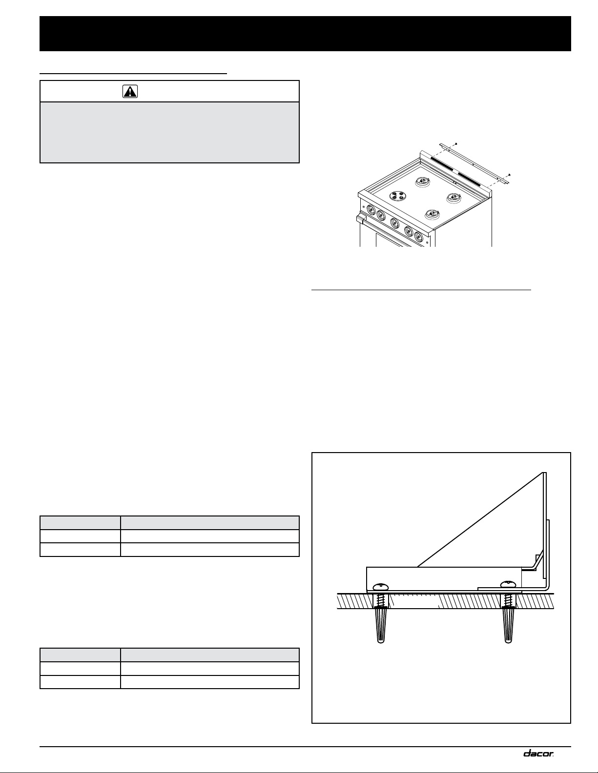
Installing Rear Trim
If installing the range in the self-rimming configuration, or if the
range will be used with a downdraft, install the rear trim piece
first.
Remove the existing screws that hold the backguard in place and
use them to attach the trim piece. (See image below.)
Installing the Anti-Tip Bracket
Locate the anti-tip bracket included in the parts box.
There are two ways to install the anti-tip bracket:
• Floor mounting (preferred method).
• Wall mounting (alternate method). Use this method if floor
mounting is not suitable. If the front panel of the range
(excluding bull nose) is more than 27 inches (68.6 cm) from
the back wall, or if the flooring is too thick (see Installing
the Anti-Tip Bracket on the Wall), use the wall mounting
method.
Sub-floor
Screws attached to
concrete sub-floor
(below floor surface).
Anti-tip
Bracket
Floor
surface
Concrete anchors shown.
Do not use anchors on a wooden sub-floor.
Anti-Tip Bracket and Flooring Cross-Section
Loading ...
Loading ...
Loading ...