User Manual Empava EMPV-36GS5B90S GAS COOKTOP
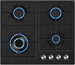
Cooktop Description
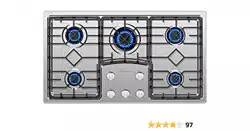
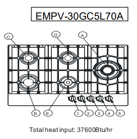
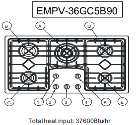
Figure 1
Operating Instructions:
Knob 1 is for wok burner A
Knob 2 is for semi-rapid burner C
Knob 3 is for auxiliary burner D
Knob 4 is for rapid burner B
| 1. Wok burner A—12000Btu/hr |
in 5.20" |
| 2. Rapid burner B—10200Btu/hr |
in 3.74" |
| 3. Semi-rapid burner C—6000Btu/hr |
in 2.56" |
| 4. Auxiliary burner D—3400Btu/hr |
in 1.77" |
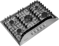
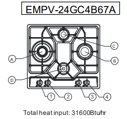
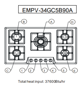
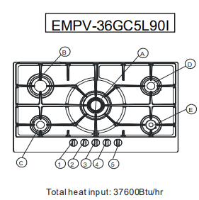
Figure 2
Operating Instructions
Knob 1 is for wok burner A
Knob 2 is for semi-rapid burner C
Knob 3 is for auxiliary burner D
Knob 4 is for rapid burner B
| 1. Wok burner A—12000Btu/hr |
in 5.20" |
| 2. Rapid burner B—10200Btu/hr |
in 3.74" |
| 3. Semi-rapid burner C—6000Btu/hr |
in 2.56" |
| 4. Auxiliary burner D—3400Btu/hr |
in 1.77" |
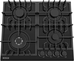
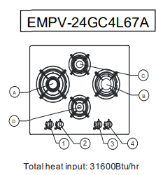
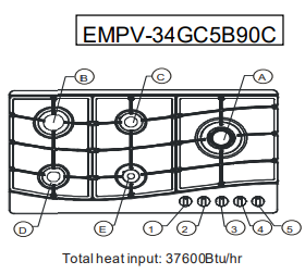
Figure 3
Operating Instructions:
Knob 1 is for semi-rapid burner C
Knob 2 is for rapid burner B
Knob 3 is for wok burner A
Knob 4 is for semi-rapid burner D
Knob 5 is for auxiliary burner E
| 1. Wok burner A—12000Btu/hr |
in 5.20" |
| 2. Rapid burner B—10200Btu/hr |
in 3.74" |
| 3. Semi-rapid burner C—6000Btu/hr |
in 2.56" |
| 4. Semi-rapid burner D—6000Btu/hr |
in 2.56" |
| 5. Auxiliary burner E—3400Btu/hr |
in 1.77" |
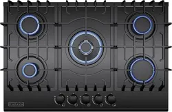
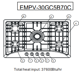
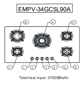
Figure 4
Operating Instructions:
Knob 1 is for rapid burner B
Knob 2 is for auxiliary burner E
Knob 3 is for semi-rapid burner C
Knob 4 is for semi-rapid burner D
Knob 5 is for wok burner A
| 1. Wok burner A—12000Btu/hr |
in 5.20" |
| 2. Rapid burner B—10200Btu/hr |
in 3.74" |
| 3. Semi-rapid burner C—6000Btu/hr |
in 2.56" |
| 4. Semi-rapid burner D—6000Btu/hr |
in 2.56" |
| 5. Auxiliary burner E—3400Btu/hr |
in 1.77" |
Figure 5
Operating Instructions
Knob 1 is for semi-rapid burner C
Knob 2 is for rapid burner B
Knob 3 is for wok burner A
Knob 4 is for semi-rapid burner D
Knob 5 is for auxiliary burner E
| 1. Wok burner A—12000Btu/hr |
in 5.20" |
| 2. Rapid burner B—10200Btu/hr |
in 3.74" |
| 3. Semi-rapid burner C—6000Btu/hr |
in 2.56" |
| 4. Semi-rapid burner D—6000Btu/hr |
in 2.56" |
| 5. Auxiliary burner E—3400Btu/hr |
in 1.77" |
Figure 6
Operating Instructions:
Knob 1 is for semi-rapid burner D
Knob 2 is for auxiliary burner E
Knob 3 is for rapid burner B
Knob 4 is for semi-rapid burner C
Knob 5 is for wok burner A
| 1. Wok burner A—12000Btu/hr |
in 5.20" |
| 2. Rapid burner B—10200Btu/hr |
in 3.74" |
| 3. Semi-rapid burner C—6000Btu/hr |
in 2.56" |
| 4. Semi-rapid burner D—6000Btu/hr |
in 2.56" |
| 5. Auxiliary burner E—3400Btu/hr |
in 1.77" |
Figure 7
Operating Instructions:
Knob 1 is for semi-rapid burner C
Knob 2 is for rapid burner B
Knob 3 is for wok burner A
Knob 4 is for semi-rapid burner D
Knob 5 is for auxiliary burner E
| 1. Wok burner A—12000Btu/hr |
in 5.20" |
| 2. Rapid burner B—10200Btu/hr |
in 3.74" |
| 3. Semi-rapid burner C—6000Btu/hr |
in 2.56" |
| 4. Semi-rapid burner D—6000Btu/hr |
in 2.56" |
| 5. Auxiliary burner E—3400Btu/hr |
in 1.77" |
Figure 8
Operating Instructions:
Knob 1 is for rapid burner B
Knob 2 is for semi-rapid burner C
Knob 3 is for wok burner A
Knob 4 is for auxiliary burner E
Knob 5 is for semi-rapid burner D
| 1. Wok burner A—12000Btu/hr |
in 5.20" |
| 2. Rapid burner B—10200Btu/hr |
in 3.74" |
| 3. Semi-rapid burner C—6000Btu/hr |
in 2.56" |
| 4. Semi-rapid burner D—6000Btu/hr |
in 2.56" |
| 5. Auxiliary burner E—3400Btu/hr |
in 1.77" |
Figure 9
Operating Instructions:
Knob 1 is for semi-rapid burner C
Knob 2 is for rapid burner B
Knob 3 is for wok burner A
Knob 4 is for semi-rapid burner D
Knob 5 is for auxiliary burner E
| 1. Wok burner A—12000Btu/hr |
in 5.20" |
| 2. Rapid burner B—10200Btu/hr |
in 3.74" |
| 3. Semi-rapid burner C—6000Btu/hr |
in 2.56" |
| 4. Semi-rapid burner D—6000Btu/hr |
in 2.56" |
| 5. Auxiliary burner E—3400Btu/hr |
in 1.77" |
Operation
Lighting
- Simply press the knob in, turn anticlockwise to ignition position (star icon).
- Press the ignition device and hold the knob till the burner is ignited
- Before releasing knob, ensure a flame is established.
- If the burner fails to ignite, put into off position and try again.
If in case of a power failure or failure of the ignition, a match or lighting devise can be used. Care must be taken when using this method
The device shall not be operated for more than 15s. If after 15s the burner has not lit, stop operating the device and open the compartment door and/ or wait at least 1 min before attempting a further ignition of the burner.
In the event of the burner flames being accidentally extinguished, turn off the burner control and do not attempt to re-ignite the burner for at least 1 min.
CAUTION: Accessible parts may be hot when the grill is in use. Young children should be kept away. As shown in Figure 10, place the burner onto the burner base one by one and stuck, rotate left and right to check if the burners are in place, the burner is placed correctly when it cannot be rotated. Finally center placed the burner cap on the burner
If you cannot light the flame even after several attempts, check the "cap" and “crown” (see diagram – figure 10) if they are in the correct position. To put the flame out, turn the knob to the symbol “O”
Description:
1. Burner cap
2. Burner crown
3. Burner base
4. Ignition electrode
5. Thermocouple

When switching on the mains, after installation or a power cut, it is quite normal for the spark generator to be activated automatically
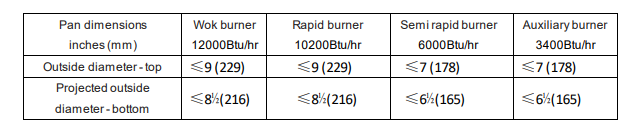
To ensure maximum burner efficiency, you had better use pots and pans with a flat bottom fitting the size of the burner used (see table).
Do not use rim based or convex-based vessels on the hotplate burners
Re-ignition:
If the flame is out for certain reasons, the safety device will cut off the gas power automatically. Turn the switch to " largest flame " position, then ignite again, you should wait for 30 seconds when you do that; Due to the air in the tong, there may be unsmooth ignition, revolve the switch to " largest flame " position and ignite again.
Maintenance and Cleaning
Before any maintenance or cleaning can be carried out, you must DISCONNECT the gas cooktop from the electricity supply. The gas cooktop is best cleaned while it is still warm; as spillage can be removed more easily than if it is left to cool.
Control Panel

The Burners
The burner caps and crowns can be removed for cleaning. Wash the burner caps and crowns using hot soapy water, and remove marks with a mild paste cleaner. A well moistened soap impregnated steel wool pad can be used with caution, if the marks are particularly difficult to remove. After cleaning, be sure to wipe dry with a soft cloth.
Ignition electrode
The electric ignition is obtained through a ceramic "electrode" and a metal electrode. Keep these components very clean, to avoid lighting difficulties, and check that the burner crown holes are not obstructed.
Thermocouple
The thermocouple is very crucial for cutting gas supply in case of flame out during cooking, be sure to keep them in very clean condition
Maintenance instructions suggesting (We suggest to clean it every six months.):
- Keeping appliance area clear and free from combustible materials, gasoline, and other flammable vapors and liquids.
- Not obstructing the flow of combustion and ventilation air
- Visually checking pilot(s) and burner flames, with pictorial representation
A>Remove the utensil supports.
B>Light burne
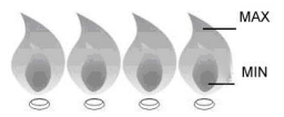
C>Turn knobs from MAX to MIN, Check the flame status, the flame in MIN position should be smaller than in MAX position, as figure shown below.
D>Always check flame before each use, see TROUBLESHOOTING if any abnormal status found.
Trouble Shooting
| Problem |
Corrective action |
| There is no spark when lighting the gas |
- Check that the unit is plugged in and the electrical supply is switched on
- Check that the RCCB has not tripped (if fitted)
- Check the mains fuse has not blown
- Check the burner cap and crown have been replaced correctly, e.g. after cleaning.
|
| The gas ring burns unevenly |
- Check the main jet is not blocked and the burner crown is clear of food particles.
- Check the burner cap and crown have been replaced correctly, e.g. after cleaning.
|
Instructions for the Installer
Overall dimensions
| For Model |
Width |
Depth |
| 24GC4B67A |
23.23in |
20.08in |
| 24GC4L67A |
25.39in |
20.67in |
| 30GC5B70C, 30GC5L70A |
29.92in |
20.08in |
| 34GC5B90A, 34GC5B90C, 34GC5L90A |
33.86in |
19.69in |
| 36GC5B90S, 36GC5L90I |
35.43in |
20.08in |
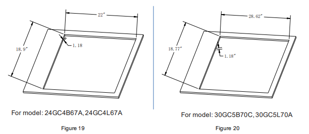
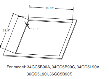
Cut out dimensions
| For Model |
Width |
Depth |
| 24GC4B67A, 24GC4L67A |
22.00 in |
18.90in |
| 30GC5B70C, 30GC5L70A |
28.62in |
18.77in |
| 34GC5B90A, 34GC5B90C, 34GC5L90A, 36GC5L90I, 36GC5B90S |
33.07in |
18.90in |
WARNING: If the cut out dimensions are too large beyond the support edge of the bottom shell, the glass panel will contact with the cabinet desktop and suffer stress, which may lead to the risk of glass breakage.
Technical Data
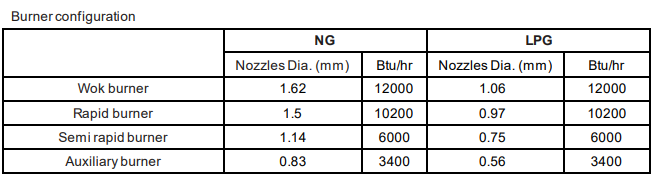
Gas Type and working pressure:
NG gas pressure at 4.0 in w.c.
LPG gas pressure at 10 in w.c.
Installation
WHEN THE GAS COOKTOP IS FIRST INSTALLED
Once the gas cooktop has been installed, it is important to remove any protective materials, which were put on in the factory. Any gas installation must be carried out by a competent person.
Important: When installing the gas cooktop above a built-in oven, the oven should be placed on two wooden strips; in the case of a joining cabinet surface, remember to leave a space of at least 1.77” x 22.05” at the back.
When installing on a built-in oven without forced ventilation, ensure that there are air inlets and outlets for ventilating the interior of the cabinet adequately
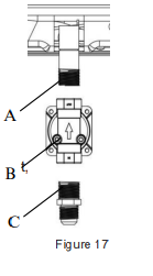
Pressure Regulator Installation
A: Cooktop air pipe joint
B: Pressure Regulator
C: Gas fitting
First, make sure that the pressure regulator arrow points toward the cooktop air pipe joint, and then fasten the pressure regulator to the cooktop air pipe. Then install the gas fitting on the other side of the pressure regulator
Gas Connection and check
D: End of fitting with 1/2 BSP male thread
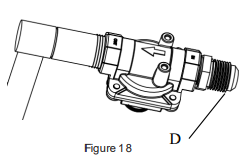
The cooktop valve is in the closed state, open the air supply valve, coated the connector with moderate amounts of soapy water, if there is air bubbles that it means there is leakage, tighten the connector and test again. If repeat 3 to 4 times and there is still air bubbles, notify professionals to deal with it.
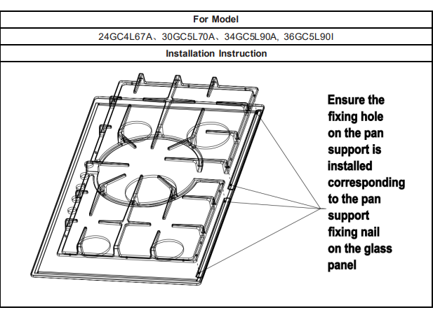
Pan Support Installation (For Glass Panel Items)
Cut Out dimensions
The dimensions of the cut-out are given in the diagram. (Dimensions are given in inch.)
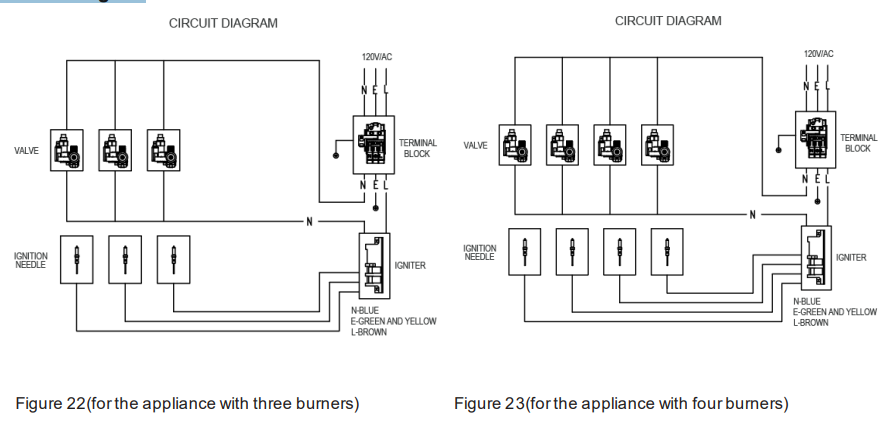
Electrical connections
Any electrical work required to install this gas cooktop should be carried out by a qualified electrician or competent person. Electrical supply type: AC
The GAS COOKTOP MUST BE EARTHED
If the cooktops to be connected to a 120V,60 Hz AC electrical supply. Before switching on, make sure the electricity supply voltage is the same as that indicated on the cooktops rating label. Ensure that the cooktops supply cable does not come into contact with surfaces with temperatures higher than 50 deg. C.
Circuit Diagram
Use with D.C battery
When your cooktop is the one fitted with D.C supply device only, you are suggested to use one 1.5V battery. Be sure that the battery is well fixed then you can follow the “Lighting” procedure. Take off the battery if you won’t use the cooktop for a long time. Check the working performance every time before cooking