Loading ...
Loading ...
Loading ...
EN
5
5
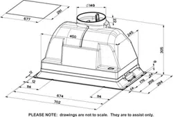
INSTALLATION
SCREWS FITTING
• The hood can be installed either directly on the bottom surface of the
wall units (min. 650 mm above the hob).
• Cut a fitted opening in the bottom surface of the wall unit, as shown.
• Fix using the 8 screws 12a provided.
13
259
497 - 677
12a
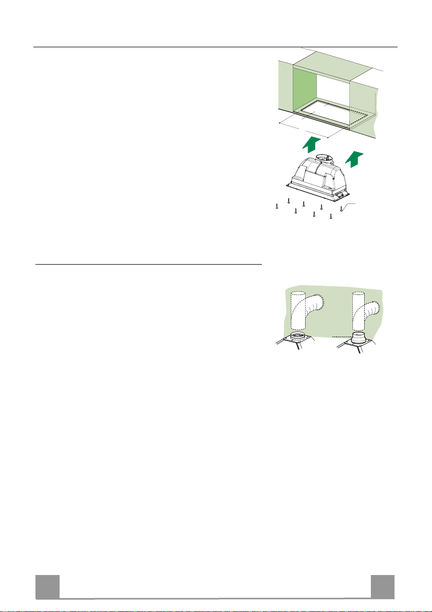
Connections
DUCTED VERSION AIR EXHAUST SYSTEM
When installing the ducted version, connect the hood to the chimney us-
ing either a flexible or rigid pipe ø 150 or 120 mm, the choice of which is
left to the installer.
• To install a ø 120 mm air exhaust connection, insert the reducer flange
9 on the hood body outlet.
• Fix the pipe in position using sufficient pipe clamps (not supplied).
• Remove possible charcoal filters.
ø 120ø 150
9
RECIRCULATION VERSION AIR OUTLET
• Connect the flange to the outlet on the shelf over the hood using a flexi-
ble or rigid pipe (ø120 or 150 mm).
• To install a ø 120 mm air exhaust connection, insert the reducer flange
9 on the hood body outlet.
• Fix the pipe in position using sufficient pipe clamps (not supplied).
• Ensure that the activated charcoal filters have been inserted.
ELECTRICAL CONNECTION
• Connect the hood to the mains through a two-pole switch having a contact gap of at least 3 mm..
Loading ...
Loading ...
Loading ...