AC/DC Wall Mount Distribution Panel
Panneau de distribution mural CA/CC
Panel de distribución de montaje en pared CA/CC
Instruction Manual
Manuel d'instructions
Manual de instrucciones
Model/Modèle/Modelo:
FDP12WA-BL

1
Welcome
English
Thank you and congratulations for purchasing this Furrion
®
AC/DC Wall Mount Distribution
Panel. Before operating your new product, please read these instructions carefully. This
instruction manual contains information for safe use, installation and maintenance of the
product.
Please keep this instruction manual in a safe place for future reference. This will ensure safe
use and reduce the risk of injury. Be sure to pass on this manual to new owners of this product.
The manufacturer does not accept responsibility for any damages due to not observing these
instructions.
If you have any further questions regarding our products, please contact us at
supportfurrion.com

2
Contents
English
Welcome ............................................................................................3
Contents ............................................................................................4
Important Safety Instructions ............................................................5
Product Overview ..............................................................................6
Rear View .................................................................................................................6
Front View ................................................................................................................6
Installation ........................................................................................7
What’s in the Box ....................................................................................................7
Mounting the Distribution Panel ............................................................................. 7
Wiring Diagram..................................................................................9
Wiring Connection ................................................................................................... 9
Care and Maintenance .......................................................................10
Replacing Circuit Breaker ....................................................................................... 10
Replacing the Power Converter .............................................................................. 10
Specifications ....................................................................................11
Warranty ............................................................................................12
3
Important Safety Instructions
English
CAUTION
● This product should be installed by an
experienced technician. Caution and
care must be taken when servicing this
equipment.
● To prevent severe shock or
electrocution consult your servicing
dealer.
● No serviceable parts inside the unit.
WARNING
● This unit employs components that
tend to produce arcs or sparks.
● To prevent fire or explosion, do not
install in compartments containing
batteries or flammable materials (LP
gas).
CAUTION
● To prevent fire, do not cover or obstruct
ventilation openings.
● Do not mount in zero-clearance
compartment. Overheating may result.
● For continued protection against risk of
fire or electric shock, replace only with
same type and rating of fuse.
CAUTION
● On a monthly basis, check the fluid
level in any battery connected to the
RV charging system, follow battery
maintenance procedures.
● This product is not ignition protected
and should not be installed in an LP
compartment.
4
Product Overview
English
● AC and DC distribution panel with max 30A/12V 15 DC distribution and 12 AC branch
circuits.
● Easy installation and removal of AC wiring strain relief.
● Simple minimalist design.
● Can be used with Furrion FCVSDC60A/ FCVSDC80A 12V series converter.
● Reverse polarity protection by fuse.
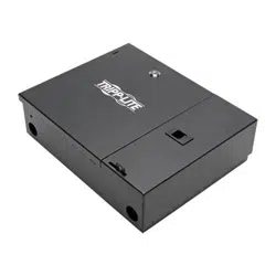
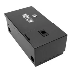
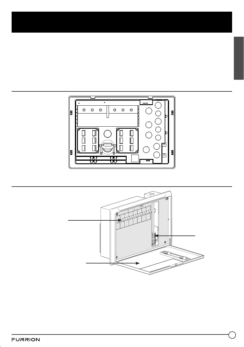
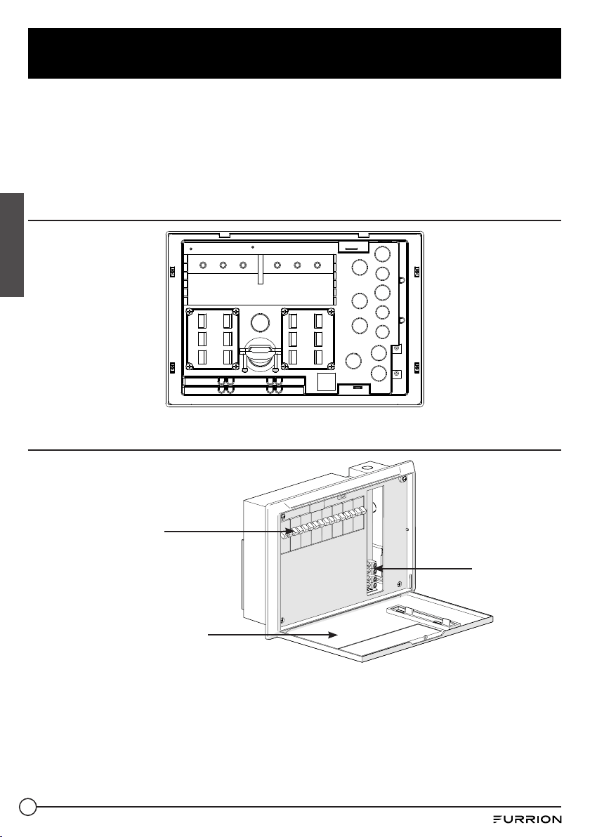
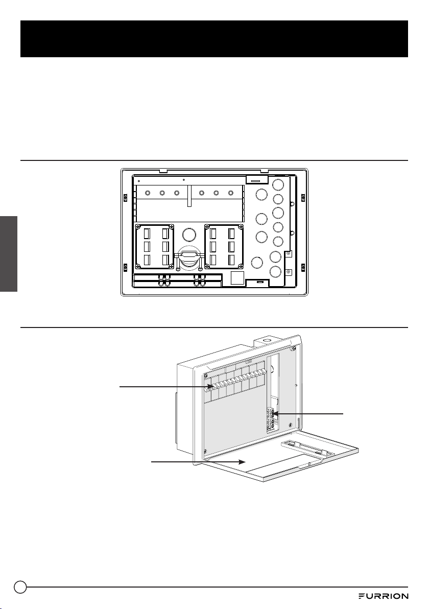
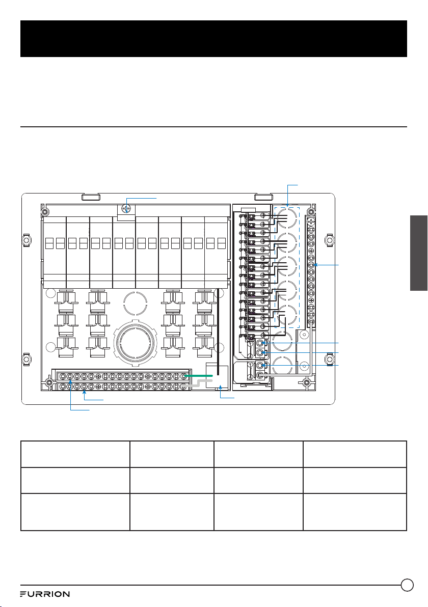
Rear View
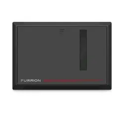
Front View
Breaker
Cover
DC Output
5
Installation
English
This product is not ignition protected
and should not be installed in an LP
compartment. For proper wire sizes and
torque requirements, refer to the label on the
back of the door assembly.
WARNING
This unit employs components that tend to
produce arcs or sparks. To prevent fire or
explosion, do not install in compartments
containing batteries or flammable
materials (LP gas).
CAUTION
● To prevent fire, do not cover or obstruct
ventilation openings. Do not mount
in zero-clearance compartment.
Overheating may result.
● For continued protection against risk of
fire or electric shock, replace only with
same type and ratings of fuse.
What’s in the Box
Make sure you have all the following items
included in the packaging. If any items are
damaged or missing, contact your dealer.
− Distribution Panel x 1
− Instruction Manual x 1
− Warranty Card x 1
Mounting the Distribution Panel
Consult a licensed electrician or an RV
technician for installation assistance.
1. Select a mounting location near the shore
power and battery (batteries). A minimum
compartment size of 3 cubic feet is
recommended.
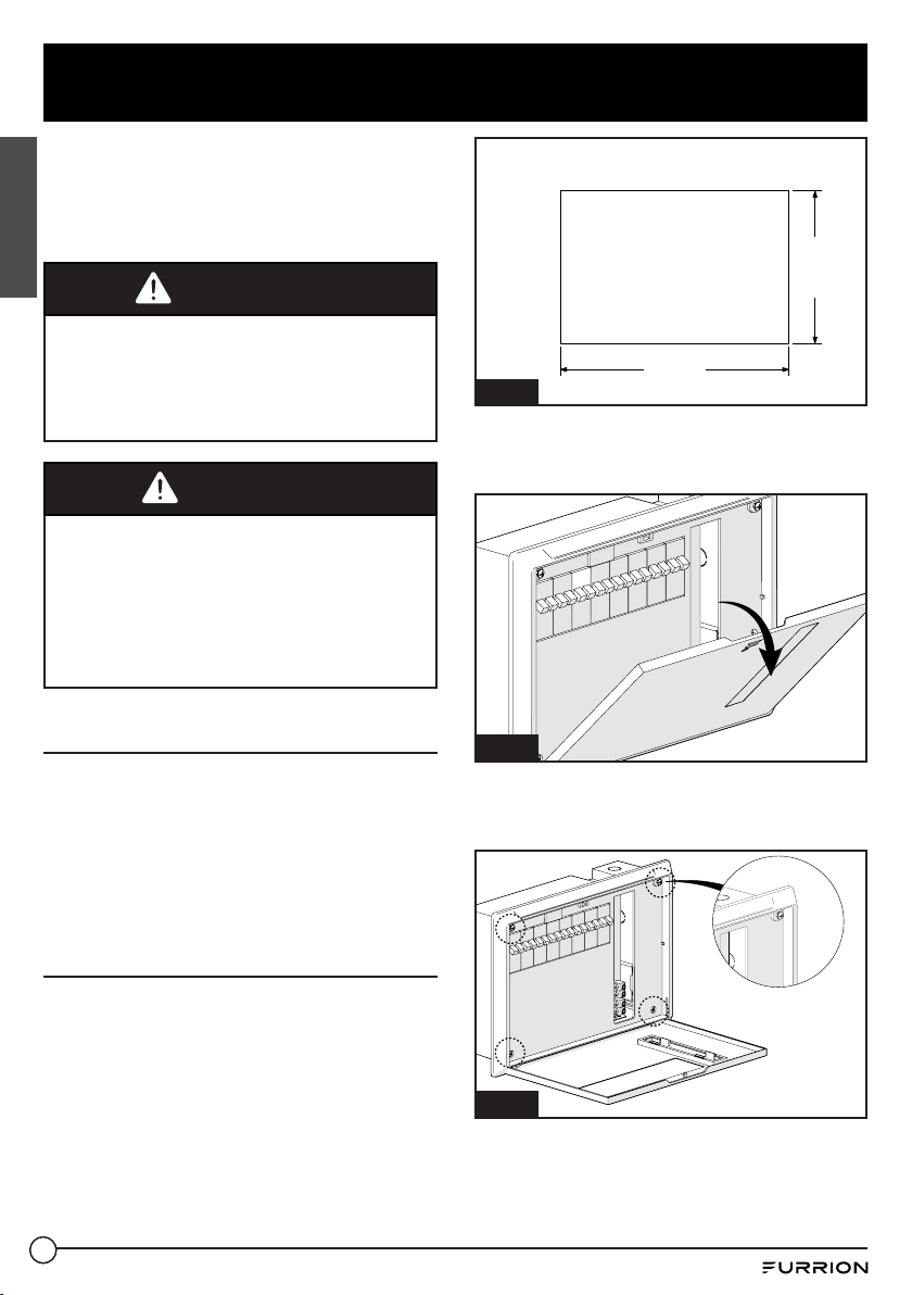
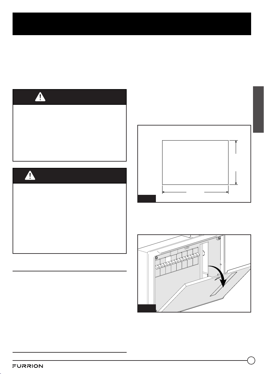
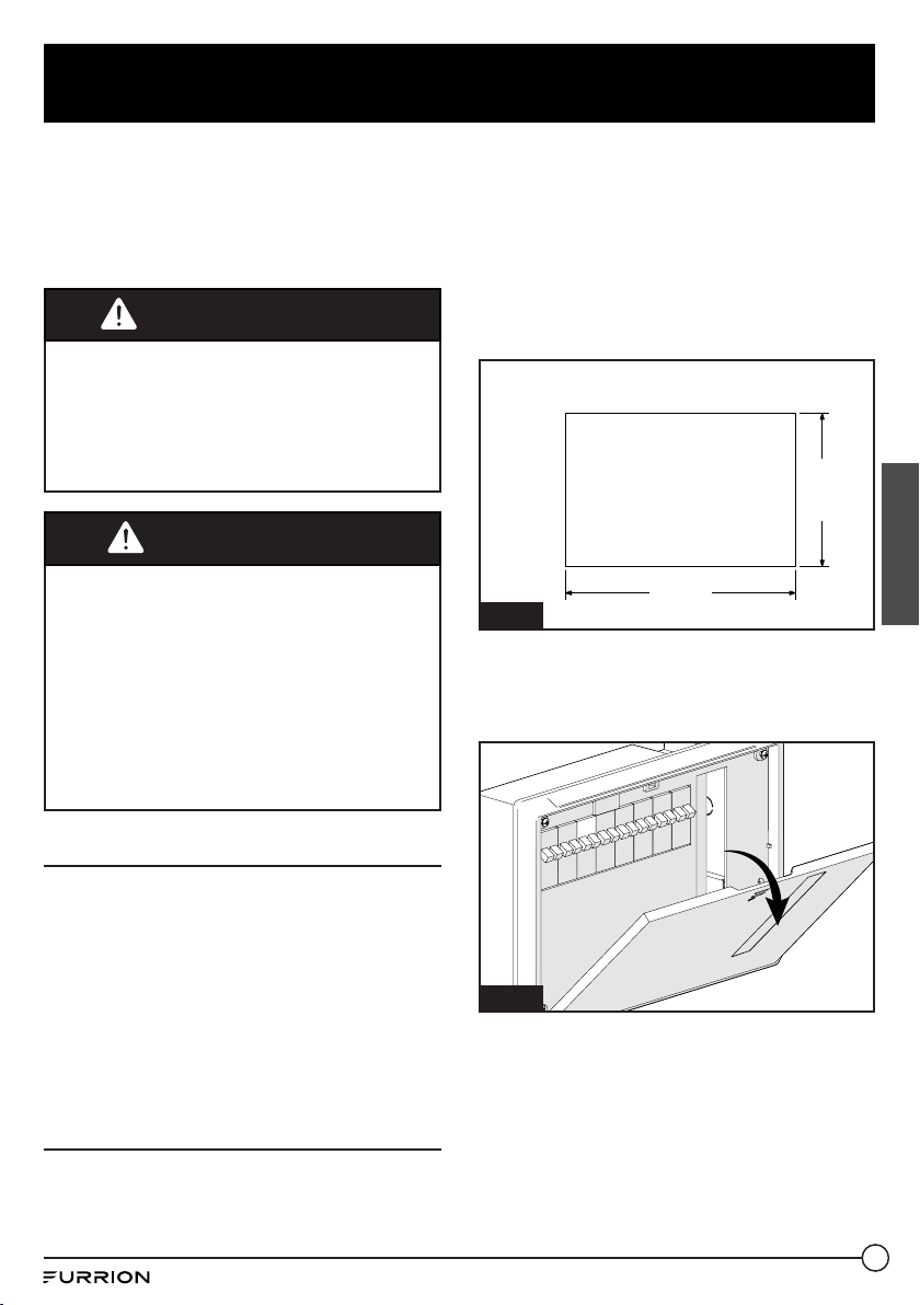
2. Cut a rough opening (as the dimension
outlined in Fig. 1) on the RV wall to allow
the power center to slide in easily.
Fig. 1
RV Wall
12
3
/8 in
315 mm
8⁄ in
217 mm
3. Push the distribution panel front cover
around to the position of ‘F” mark and
rotate downwards to fully open it. (Fig. 2)
Fig. 2
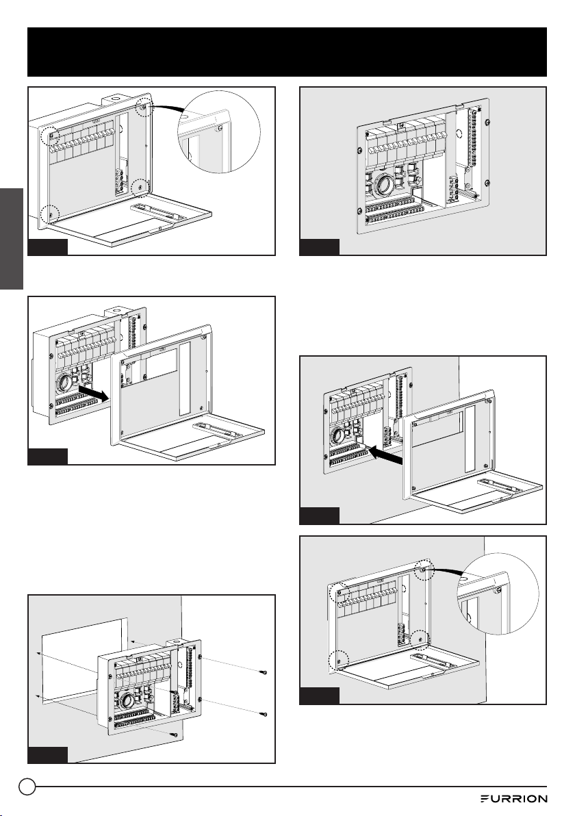
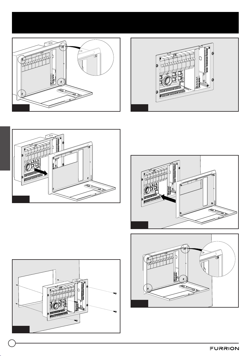
4. Loosen the screws that hold the housing
at the four corners using a Phillips
screwdriver. (Fig. 3)
Fig. 3
5. Pull to remove the housing from the unit.
(Fig. 4)

6
Installation
English
Fig. 4
6. Connect the distribution panel to the
battery. See ‘Wiring Diagram’ section on
how to connect the wires.
7. Slide the distribution panel in the opening
area and fix with 4 self-tapping screws
(#8-18 thread) (not supplied). (Fig. 5 and
Fig. 6)
Fig. 5
Fig. 6
8. Replace the housing to the distribution
panel and tighten the screws at the four
corners. (Fig. 7 and Fig. 8)
NOTE: Do not over tighten. Damage to
the housing may occur which will void the
warranty.
Fig. 7
Fig. 8
9. Test the distribution panel under full
load conditions in its intended mounting
location to ensure proper ventilation.
7
Wiring Diagram
English
IMPORTANT: Remember to select the proper gauge wire for the load, according to the National
Electric Code (NEC) and RVIA. Be sure to use appropriate connector and strain reliefs to secure
the wires to the distribution panel.
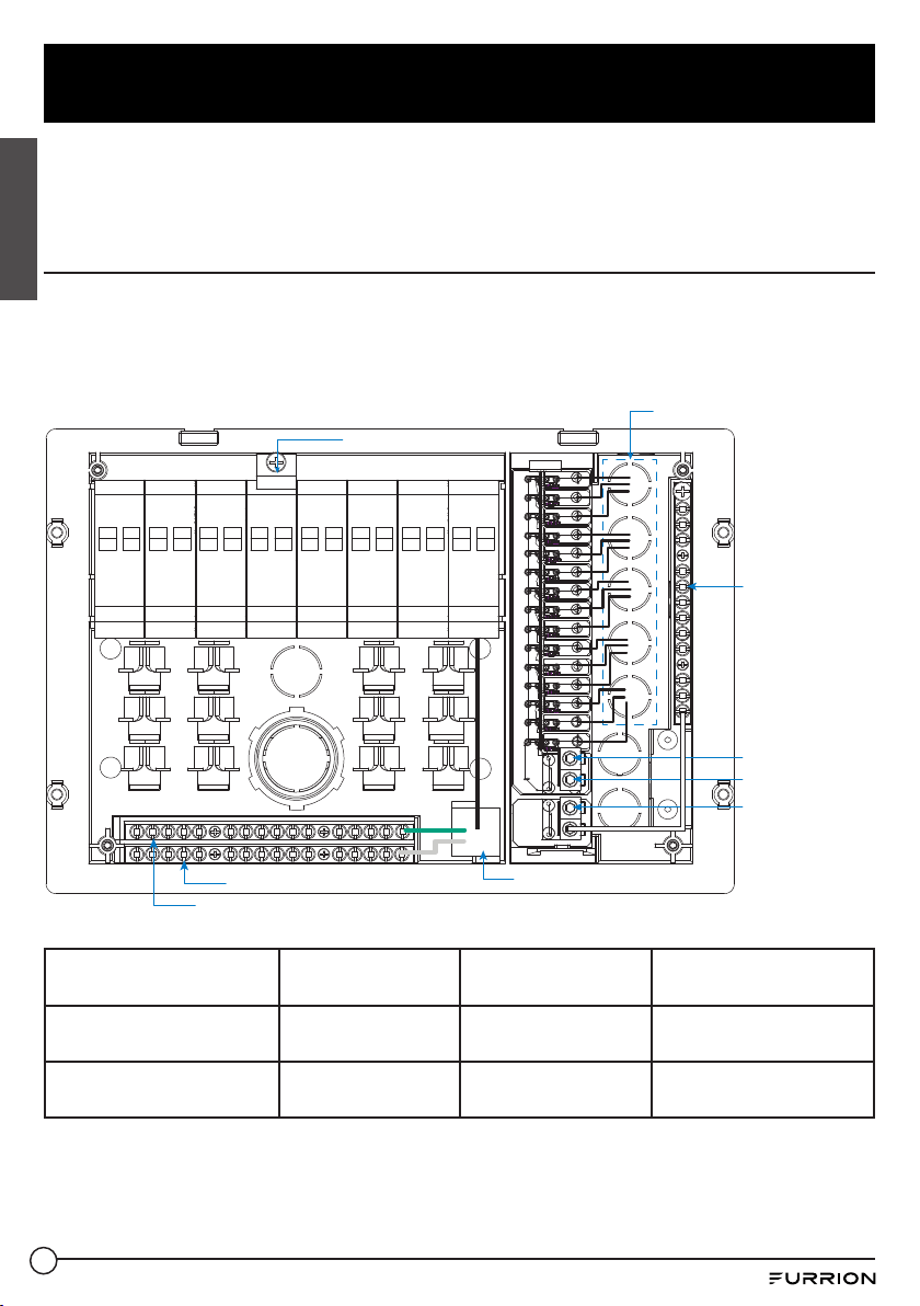
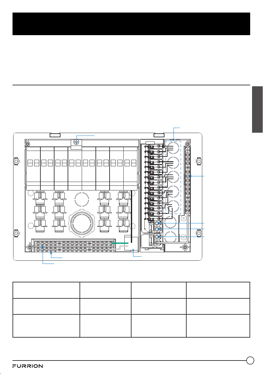
Wiring Connection
The fuse rating that the manufacturer suggests for the output fuses will be marked on the unit.
Replace only with same type and rating.
NOTE: If the reverse polarity protection fuses are blown during connection, replace the fuses
with the same rating as the original.
Chasis Ground (Green and Ground Wires)
Main Breaker Holder
DC Output
50A
or
30A
50A
LINE
20A Receptacle
To Battery +
Negative
Battery
terminal
From Converter +
From Converter -
Neutral Bar (White Wire)
Terminal Description Max. Temperature
(°C)
Torque (In. -lbs) Wire Gauges (AWG)
Terminal of Ground and
Neutral Bar
90 25; 30; 35 10-14; 8; 6
DC Fuse Panel Lugs
Positive and Negative
70 25; 32; 45 10-14; 8; 6
8
Care and Maintenance
English
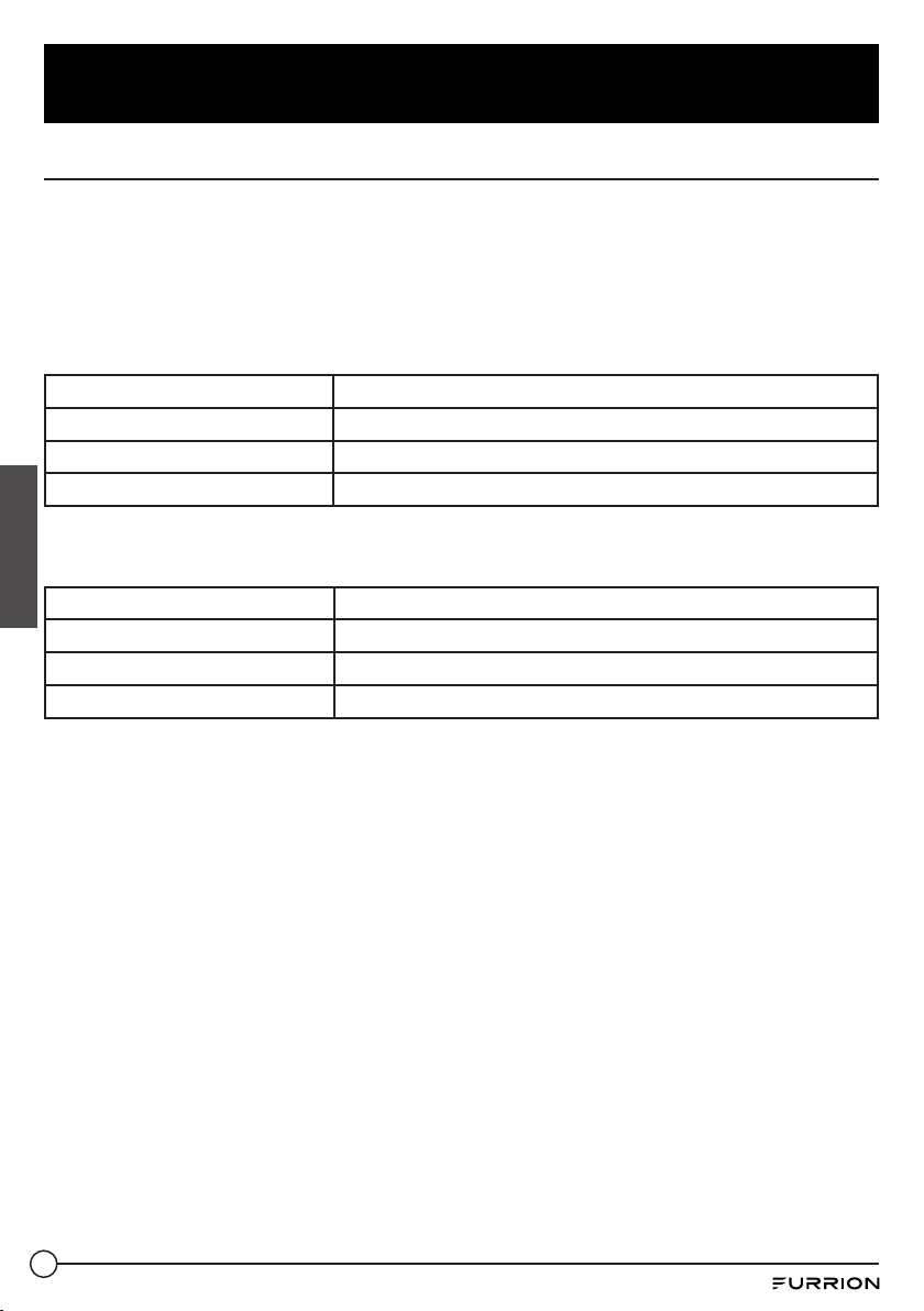
Replacing Circuit Breaker
A replacement or additional circuit breaker shall be of the same manufacturer, type
designation, and equal or greater interrupting rating, not to exceed 50A.
“Short-Circuit-Current” rating for the breaker should be 10,000A at 120/240 Volt AC.
UL
®
-Listed Main Circuit Breakers, rated for 30/50Amp 120V/240Vac
Acceptable circuit breakers are as follows:
Manufacturer Model/Cat. No./Type
Eaton BR
ITE/Siemens Type QP
Square D Type HOM
UL
®
-Listed Branch Circuit Breakers, rated for 120/240Vac, 20A or 15A
Acceptable circuit breakers are as follows:
Manufacturer Model/Cat. No./Type
Eaton BR
ITE/Siemens Type QP or QT
Square D Type HOMT
Replacing the Power Converter
IMPORTANT: Make sure all power is disconnected before proceeding.
If you should need to replace the power converter for any reason, follow the steps below to
safely remove the converter section.
1. Remove the neutral, ground and hot wires that lead to the converter on the AC side.
2. Remove the converter output wires from the DC board, ground and positive.
3. Finally unscrew the screws that holds the metal converter plate to the plastic housing.
For factory repairs, return only the converter section. Make sure you use proper packaging to
ensure the product’s safe arrival.
Do not replace the converter section unless the following checks have been performed:
1. Use an AC voltmeter to check for the proper voltage at the 120VAC breaker that the
converter is connected to. This voltage should be between 105 and 130 volts.
2. Remove the reverse battery fuses and check the converter output from the CONVERTER
GND to the CONVERTER POS terminals on the DC board. This should be 13.6VDC.
3. Check the reverse battery fuses. These fuses will only blow if the battery or DC output leads
were connected reversed, even for a moment. If they are blown check the polarity of the
battery connections before replacing them.
4. If the Converter output is not present and there is AC to the converter, the converter is
defective.
9
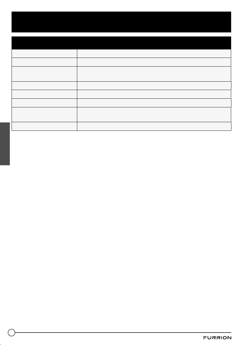
Specifications
English
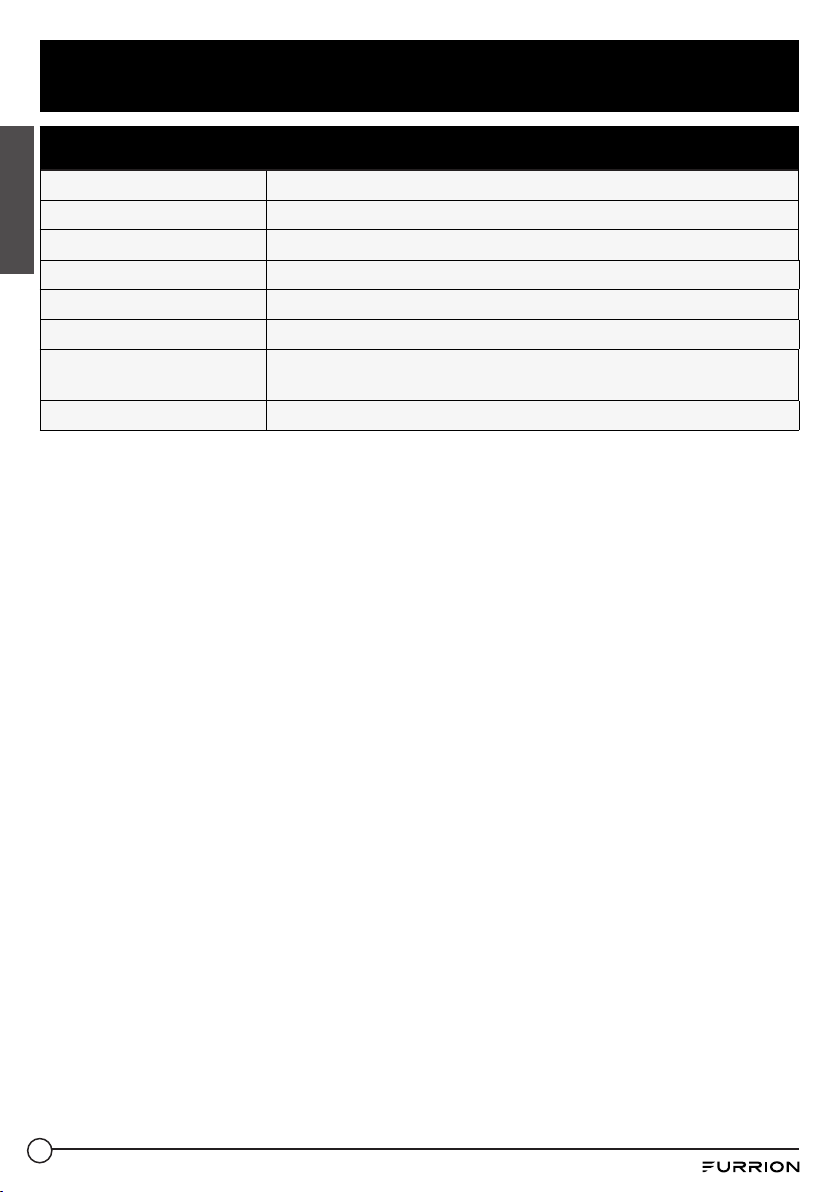
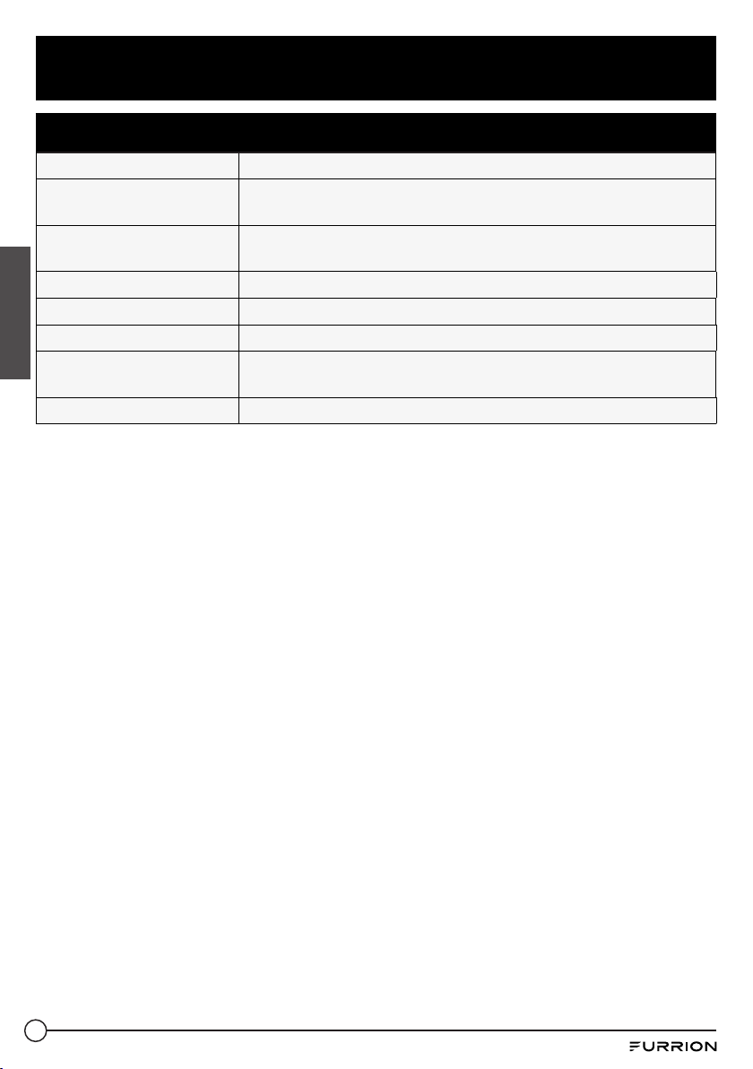
Technical Specification
System Voltage Input 120Vac 30Amp or 240Vac 50Amp.
AC Distribution Max. 12 branches (7 for 30A main; 12 For 50A main)
AC Main Breakers 30Amp or 50Amp x2
AC Receptacle 5-20R 120V 20A receptacle
DC Circuits (Total) 15DC outputs (30Amp x2CH, 20Amp x13CH)
DC Terminal bar Built-in negative battery terminal
Fuse Status Indicator LED
The LED displays no light when fuse is in good condition. It will
light with RED when fuse is broken.
Certification UL67

10
English
Warranty
Furrion warrants for a period of 1 year from date of retail purchase by the original end-use
purchaser, that this product, when delivered to you in new condition, in original packaging,
from a Furrion authorized reseller and used in normal conditions, is free from any defects
in manufacturing, materials, and workmanship. In case of such defect, Furrion shall replace
or repair the product at no charge to you. This warranty does not cover: products where the
original serial numbers have been removed, altered or cannot readily be determined; damage
or loss caused by accident, misuse, abuse, neglect, product modification, failure to follow
instructions in instruction manual, commercial or industrial use; damage or loss caused to the
decorative surface of product; to any data, software or information; and normal wear and tear.
This warranty only protects the original end-user (“you”) and is not transferable; any attempt to
transfer this warranty shall make it immediately void. This warranty is only valid in the country
of purchase.
THIS WARRANTY AND REMEDIES SET FORTH ABOVE ARE EXCLUSIVE AND IN LIEU OF ALL
OTHER WARRANTIES, REMEDIES AND CONDITIONS, WHETHER ORAL OR WRITTEN, EXPRESS
OR IMPLIED. FURRION SPECIFICALLY DISCLAIMS ANY AND ALL IMPLIED WARRANTIES,
INCLUDING, WITHOUT LIMITATION, WARRANTIES OF MERCHANTABILITY AND FITNESS FOR
A PARTICULAR PURPOSE. IF FURRION CANNOT LAWFULLY DISCLAIM IMPLIED WARRANTIES
UNDER THIS LIMITED WARRANTY, ALL SUCH WARRANTIES, INCLUDING WARRANTIES
OF MERCHANTABILITY AND FITNESS FOR A PARTICULAR PURPOSE ARE LIMITED TO THE
DURATION OF THIS WARRANTY.
No Furrion reseller, agent, or employee is authorized to make any modification, extension, or
addition to this warranty.

11
English
Warranty
FURRION IS NOT RESPONSIBLE FOR DIRECT, INDIRECT, SPECIAL, INCIDENTAL OR
CONSEQUENTIAL DAMAGES RESULTING FROM ANY BREACH OF WARRANTY OR CONDITION,
OR UNDER ANY OTHER LEGAL THEORY, INCLUDING BUT NOT LIMITED TO LOST PROFITS,
DOWNTIME, GOODWILL, DAMAGE TO OR REPLACEMENT OF ANY EQUIPMENT OR PROPERTY,
ANY COSTS OF RECOVERING, REPROGRAMMING, OR REPRODUCING ANY PROGRAM OR DATA
STORED IN OR USED WITH FURRION PRODUCTS. FURRION’S TOTAL LIABILITY IS LIMITED
TO THE REPAIR OR REPLACEMENT OF THIS PRODUCT PURSUANT TO THE TERMS OF THIS
WARRANTY.
SOME STATES DO NOT ALLOW THE EXCLUSION OR LIMITATION OF INCIDENTAL OR
CONSEQUENTIAL DAMAGES OR EXCLUSIONS OR LIMITATIONS ON THE DURATION OF IMPLIED
WARRANTIES OR CONDITIONS, SO THE ABOVE LIMITATIONS OR EXCLUSIONS MAY NOT APPLY
TO YOU. THIS WARRANTY GIVES YOU SPECIFIC LEGAL RIGHTS, AND YOU MAY ALSO HAVE
OTHER RIGHTS THAT VARY BY STATE OR (WHERE APPLICABLE IN THE COUNTRIES WHERE
FURRION HAS NON-US/CANADIAN AUTHORIZED DEALERS) COUNTRY. NO ACTION OR CLAIM
TO ENFORCE THIS WARRANTY SHALL BE COMMENCED AFTER THE EXPIRATION OF THE
WARRANTY PERIOD.
Keep your receipt, delivery slip, or other appropriate payment record to establish the warranty
period. Service under this warranty must be obtained by contacting Furrion at
Product features or specifications as described or illustrated are subject to change without
notice.

12
Bienvenue
Français
Merci et félicitations pour l’achat de ce panneau de distribution mural CA/CC de Furrion
®
. Avant
d’utiliser votre nouveau produit, veuillez lire ces instructions attentivement. Vous serez ainsi
assuré d’utiliser ce produit de manière sécuritaire tout en réduisant les risques de blessures.
Ce manuel d’instructions contient des renseignements portant sur l’installation, l’entretien du
produit et son utilisation sécuritaire.
Veuillez conserver ces instructions en lieu sûr pour pouvoir les consulter ultérieurement.
N’oubliez pas de remettre ce manuel à tout nouveau propriétaire de ce produit.
Le fabricant n’accepte aucune responsabilité quant aux dommages causés à la suite du non-
respect de ces instructions.
Pour toute question sur nos produits, veuillez communiquer avec nous à l’adresse:

13
Contenu
Français
Bienvenue ..........................................................................................14
Contenu .............................................................................................15
Consignes de sécurité importantes ...................................................16
Présentation du produit .....................................................................17
Vue arrière ...............................................................................................................17
Vue de face ..............................................................................................................17
Installation ........................................................................................18
Contenu de la boîte .................................................................................................18
Montage du panneau de distribution ......................................................................18
Schéma de câblage ............................................................................20
Connexion de câblage .............................................................................................20
Soins et entretien ..............................................................................21
Remplacement du disjoncteur ................................................................................21
Remplacement du convertisseur de puissance .....................................................22
Spécifications ....................................................................................23
Garantie .............................................................................................24
14
Consignes de sécurité importantes
Français
MISE EN GARDE
● Ce produit doit être installé par un
technicien expérimenté. Une attention
et des précautions particulières doivent
être prises lors de l’entretien de cet
équipement.
● Pour éviter toute décharge électrique
grave ou électrocution, consultez votre
détaillant.
● Il n’y a aucune pièce réparable à
l’intérieur de l’unité.
ATTENTION
● Cette unité utilise des composants qui
ont tendance à produire des arcs ou
des étincelles.
● Pour éviter un incendie ou une
explosion, ne pas l’installer dans des
compartiments contenant des batteries
ou des matériaux inflammables (p.ex.,
gaz de pétrole liquéfié).
MISE EN GARDE
● Pour éviter les incendies, ne pas
couvrir ou obstruer les ouvertures de
ventilation. Ne pas monter l’unité dans
un compartiment à dégagement zéro.
Une surchauffe peut en résulter.
● Pour une protection continue contre les
risques d’incendie ou d’électrocution,
remplacez le fusible uniquement par
un fusible du même type et du même
calibre.
MISE EN GARDE
● Tous les mois, vérifiez le niveau de
liquide dans toute batterie connectée
au système de charge du VR et suivez
les procédures d’entretien de la
batterie.
● Ce produit n’est pas protégé contre
l’inflammabilité et ne doit pas être
installé dans un compartiment de gaz
de pétrole liquéfié (GPL).
15
Présentation du produit
Français
● Panneau de distribution CA et CC avec distribution maximale de 30A/12V 15CC et circuits
de dérivation 12CA.
● Facilité d’installation et de retrait du dispositif anti-traction du câblage CA.
● Conception minimaliste simple.
● Peut être utilisé avec le convertisseur Furrion de série FCVSDC60A / FCVSDC80A 12V.
● Protection par fusible contre l’inversion de polarité.
Vue arrière
Vue de face
Disjoncteur
Couvercle
Sortie CC
16
Installation
Français
Ce produit n’est pas protégé contre
l’inflammabilité et ne doit pas être installé
dans un compartiment de gaz de pétrole
liquéfié (GPL). Pour connaître les calibres
de fil et les exigences de couple de serrage,
reportez-vous à l’étiquette située à l’arrière
de la portière.
ATTENTION
● Cette unité utilise des composants qui
ont tendance à produire des arcs ou
des étincelles.
● Pour éviter un incendie ou une
explosion, ne pas l’installer dans des
compartiments contenant des batteries
ou des matériaux inflammables (p.ex.,
gaz de pétrole liquéfié).
MISE EN GARDE
● Pour éviter les incendies, ne pas
couvrir ou obstruer les ouvertures de
ventilation. Ne pas monter l’unité dans
un compartiment à dégagement zéro.
Une surchauffe peut en résulter.
● Pour une protection continue contre les
risques d’incendie ou d’électrocution,
remplacez le fusible uniquement par
un fusible du même type et du même
calibre.
Contenu de la boîte
Assurez-vous que tous les articles suivants
sont inclus dans l’emballage. Si un article est
endommagé ou manquant, contactez votre
détaillant.
− Panneau de distribution x 1
− Manuel d’instructions x 1
− Carte de garantie x 1
Montage du panneau de
distribution
Consultez un électricien agréé ou un
technicien de VR pour obtenir de l’aide lors
de l’installation.
1. Sélectionnez un emplacement de
montage à proximité de l’alimentation
à quai et de la batterie (batteries). Une
taille de compartiment minimum de
3pieds cubes est recommandée.
2. Couper une ouverture grossière (comme
la dimension indiquée à la Fig. 1) sur la
paroi du VR pour permettre au centre
d’alimentation de s’insérer facilement.
Fig. 1
Paroi du VR
12
3
/8 in
315 mm
8⁄ in
217 mm
3. Pressez le couvercle avant du panneau
de distribution autour du repère «F» et
faites-le pivoter vers le bas pour l’ouvrir
complètement. (Fig. 2)
Fig. 2
4. Desserrez les vis qui maintiennent le
boîtier aux quatre coins à l’aide d’un
tournevis cruciforme. (Fig. 3)
17
Installation
Français
Fig. 3
5. Tirez pour retirer le boîtier de l’unité. (Fig.
4)
Fig. 4
6. Connectez le panneau de distribution à
la batterie. Voir la section «Schéma de
câblage» pour savoir comment connecter
les fils.
7. Faites glisser le panneau de distribution
dans la zone d’ouverture et fixez-le avec
4vis autotaraudeuses (filetage no8-18)
(non fournies). (Fig. 5 et Fig. 6)
Fig. 5
Fig. 6
8. Replacez le boîtier dans le panneau de
distribution et serrez les vis aux quatre
coins. (Fig. 7 et Fig. 8)
REMARQUE: Ne pas trop serrer. Le
boîtier pourrait subir des dommages, ce
qui annulerait la garantie.
Fig. 7
Fig. 8
9. Testez le panneau de distribution dans
des conditions de pleine charge dans son
emplacement de montage prévu pour vous
assurer que la ventilation est adéquate.
18
Schéma de câblage
Français
IMPORTANT: N’oubliez pas de sélectionner le calibre de fil approprié pour la charge,
conformément au National Electric Code (NEC) et à l’industrie du VR. Assurez-vous d’utiliser
un connecteur approprié et des réducteurs de tension pour fixer les fils au panneau de
distribution.
Connexion de câblage
Le calibre de fusible suggéré par le fabricant pour les fusibles de sortie sera marqué sur
l’unité. Remplacez les fusibles uniquement par des fusibles du même type et du même calibre.
REMARQUE: Si les fusibles de protection contre l’inversion de polarité grillent pendant la
connexion, remplacez les fusibles par des fusibles du même calibre que ceux à l’origine.
Masse du châssis (fils vert et de mise à la masse)
Support de Disjoncteur principal
Sortie CC
50A
ou
30A
50A
LIGNE
Prise 20A
Vers batterie +
Borne de
batterie
négative
Depuis convertisseur +
Depuis convertisseur -
Barre neutre (fil blanc)
Description du terminal Température
max. (°C)
Couple (lb-po) Calibres de fil (AWG)
Terminal de mise à la
masse et barre neutre
90 25; 30; 35 10-14; 8; 6
Cosses de panneau de
fusible CC, positif et
négatif
70 25; 32; 45 10-14; 8; 6

19
Soins et entretien
Français
Remplacement du disjoncteur
Un disjoncteur de remplacement ou un disjoncteur supplémentaire doit provenir du même
fabricant, avoir la même désignation de type et une valeur de coupure égale ou supérieure, ne
dépassant pas 50A.
Le courant nominal de court-circuit pour le disjoncteur doit être de 10000A à 120/240voltsCA.
Disjoncteurs principaux homologués UL®, homologués pour 30/50A 120V/240Vc.a.
Les disjoncteurs acceptables sont les suivants:
Fabricant Modèle / Cat. N° / Type
Eaton BR
ITE/Siemens Type QP
Square D Type HOM
Disjoncteurs de dérivation homologués UL®, homologués pour 120/240Vc.a., 20A ou 15A
Les disjoncteurs acceptables sont les suivants:
Fabricant Modèle / Cat. N° / Type
Eaton BR
ITE/Siemens Type QP ou QT
Square D Type HOMT

20
Soins et entretien
Français
Remplacement du convertisseur de puissance
IMPORTANT: Assurez-vous que l’alimentation est entièrement débranchée avant de
continuer.
Si vous devez remplacer le convertisseur de puissance pour une raison quelconque, suivez les
étapes ci-dessous pour retirer la section du convertisseur en toute sécurité.
1. Retirez les fils d’apport de courant, neutre et de mise à la masse acheminés au
convertisseur du côté CA.
2. Retirez les fils de sortie du convertisseur depuis le circuit intégré CC, la mise à la masse et
le positif.
3. Enfin, dévissez les vis qui maintiennent la plaque métallique du convertisseur sur le boîtier
en plastique.
Pour les réparations en usine, renvoyez uniquement la section du convertisseur. Assurez-vous
d’utiliser un emballage approprié pour que le produit puisse arriver intact.
No vuelva a colocar la sección del convertidor a menos que se hayan realizado las siguientes
comprobaciones:
1. Use un voltímetro de CA para verificar el voltaje adecuado en el interruptor de 120VCA al
que está conectado el convertidor. Este voltaje debe estar entre 105 y 130 voltios.
2. Retire los fusibles de la batería inversa y verifique la salida del convertidor desde el
CONVERTIDOR GND a los terminales del CONVERTIDOR POS en la placa de CC. Esto
debería ser 13,6VCC.
3. Verifique los fusibles de la batería inversa. Estos fusibles solo se dispararán si la batería
o los cables de salida de CC estuvieran conectados en reversa, incluso por un momento.
Si están quemados, verifique la polaridad de las conexiones de la batería antes de
reemplazarlas.
4. Si la salida del convertidor no está presente y hay CA hacia el convertidor, el convertidor
está defectuoso.
21
Spécifications
Français
Spécifications techniques
Tension du système Entrée 120Vc.a. 30A ou 240Vc.a. 50A
Distribution CA
Max. 12dérivations (7 pour le 30A principal, 12 pour le 50A
principal)
Disjoncteurs principaux
CA
30A ou 50A x 2
Prise CA Prise 5-20R 120V 20A
Circuits CC (Total) Sorties 15CC (30A x 2voies, 20A x 13voies)
Barre de connexion CC Borne de batterie négative intégrée
Voyant à DEL d’état du
fusible
La DEL ne s’allume pas lorsque le fusible est en bon état. Elle
s’allume en ROUGE lorsque le fusible est brisé.
Certification UL67

22
Français
Garantie
FURRION GARANTIT, PENDANT UNE PÉRIODE D’UN AN À PARTIR DE LA DATE DE L’ACHAT
AU DÉTAIL PAR L’UTILISATEUR FINAL INITIAL, QUE CE PRODUIT, S’IL EST LIVRÉ À L’ÉTAT
NEUF, DANS SON EMBALLAGE ORIGINAL, PAR UN REVENDEUR FURRION AUTORISÉ ET
UTILISÉ EN CONDITIONS NORMALES, EST LIBRE DE TOUT DÉFAUT DE FABRICATION, DE
MATÉRIEL ET DE MAIND’ŒUVRE. EN CAS DE DÉFAUT, FURRION S’ENGAGE À REMPLACER
OU À RÉPARER LE PRODUIT GRATUITEMENT. CETTE GARANTIE EXCLUT CE QUI SUIT :
PRODUITS DONT LE NUMÉRO DE SÉRIE ORIGINAL A ÉTÉ ENLEVÉ, MODIFIÉ OU RENDU
ILLISIBLE, LES DOMMAGES OU LES PERTES CAUSÉS PAR UN ACCIDENT, UNE MAUVAISE
UTILISATION, LA NÉGLIGENCE, LA MODIFICATION DU PRODUIT OU LE MANQUEMENT À
SUIVRE LES CONSIGNES DU GUIDE DE L’UTILISATEUR, L’UTILISATION COMMERCIALE OU
INDUSTRIELLE, LES DOMMAGES OU LES PERTES CAUSÉES À LA SURFACE DÉCORATIVE
DU PRODUIT, LES DOMMAGES CAUSÉS AUX DONNÉES, LOGICIELS OU RENSEIGNEMENTS,
AINSI QUE L’USURE NORMALE. LA PRÉSENTE GARANTIE PROTÈGE UNIQUEMENT
L’UTILISATEUR FINAL INITIAL (VOUS), ET NE PEUT ÊTRE CÉDÉE À QUICONQUE. TOUTE
TENTATIVE DE CESSION DE LA PRÉSENTE GARANTIE AURA POUR EFFET SON ANNULATION
IMMÉDIATE. LA PRÉSENTE GARANTIE EST UNIQUEMENT VALIDE DANS LE PAYS D’ACHAT.
LA PRÉSENTE GARANTIE ET LES RECOURS PRÉCÉDEMMENT DÉFINIS SONT EXCLUSIFS ET
REMPLACENT TOUTES LES AUTRES RECOURS, GARANTIES ET CONDITIONS, QU’ILS SOIENT
ORAUX OU ÉCRITS, EXPLICITES OU IMPLICITES. FURRION DÉCLINE SPÉCIFIQUEMENT
TOUTES LES GARANTIES IMPLICITES, Y COMPRIS, SANS S’Y LIMITER, LES GARANTIES
DE QUALITÉ MARCHANDE ET D’ADÉQUATION À UN USAGE PARTICULIER. SI FURRION NE
PEUT LÉGALEMENT DÉCLINER LES GARANTIES IMPLICITES DÉCOULANT DE LA PRÉSENTE
GARANTIE LIMITÉE, TOUTES CES GARANTIES, Y COMPRIS LES GARANTIES DE QUALITÉ
MARCHANDE ET D’ADAPTATION À UN USAGE PARTICULIER, SONT LIMITÉES À LA DURÉE DE
VALIDITÉ DE LA PRÉSENTE GARANTIE.
Aucun revendeur, agent ou employé de furrion n’est autorisé à modifier, prolonger ou élargir la
présente garantie.

23
Français
Garantie
FURRION DÉCLINE TOUTE RESPONSABILITÉ POUR TOUT PRÉJUDICE DIRECT, INDIRECT,
SPÉCIAL, ACCESSOIRE OU CONSÉCUTIF RÉSULTANT DE TOUT MANQUEMENT DE GARANTIE
OU DE CONDITION, OU RECONNU PAR TOUTE THÉORIE JURIDIQUE, INCLUANT SANS
LIMITATION LES PERTES DE BÉNÉFICES, DE TEMPS DE FONCTIONNEMENT, DE BIENS
INCORPORELS, LES DOMMAGES À TOUT APPAREIL OU BIEN OU LE REMPLACEMENT DE
TOUT BIEN OU ÉQUIPEMENT, TOUT COÛT DE RÉCUPÉRATION, DE REPROGRAMMATION OU
DE REPRODUCTION DE TOUT PROGRAMME OU DE TOUTE DONNÉE ENREGISTRÉ DANS LES
PRODUITS FURRION OU UTILISÉS AVEC CEUX-CI. LA RESPONSABILITÉ TOTALE DE FURRION
SE LIMITE À LA RÉPARATION OU AU REMPLACEMENT DE CE PRODUIT CONFORMÉMENT AUX
CONDITIONS DE LA PRÉSENTE GARANTIE.
CERTAINS ÉTATS N’AUTORISENT PAS LES EXCLUSIONS OU LES LIMITATIONS DES
PRÉJUDICES ACCESSOIRES OU CONSÉCUTIFS, NI LES EXCLUSIONS OU LIMITATIONS DE
LA DURÉE DES GARANTIES OU CONDITIONS IMPLICITES. POUR CE MOTIF, LES LIMITES ET
EXCLUSIONS PRÉCÉDEMMENT ÉNONCÉES POURRAIENT NE PAS S’APPLIQUER À VOUS.
LA PRÉSENTE GARANTIE VOUS CONFÈRE CERTAINS DROITS JURIDIQUES SPÉCIFIQUES,
QUI POURRAIENT S’AJOUTER À D’AUTRES DROITS QUI VOUS SONT CONFÉRÉS PAR VOTRE
JURIDICTION (DANS LES PAYS OÙ FURRION COMPTE DES DÉTAILLANTS AUTORISÉS HORS
CANADA ET ETATS-UNIS). AUCUNE ACTION OU RÉCLAMATION POUR FAIRE APPLIQUER LA
PRÉSENTE GARANTIE NE POURRA ÊTRE INITIÉE APRÈS L’ÉCHÉANCE DE LA PÉRIODE DE
GARANTIE.
Conserver votre reçu d’achat, bon de livraison ou tout autre justificatif de paiement pour
établir la période de garantie. Les réparations aux termes de la présente garantie doivent être
réclamées auprès de Furrion: [email protected]
Les fonctionnalités et les détails techniques du produit tels qu’ils sont décrits ou illustrés
peuvent changer sans préavis.

24
Bienvenido
Español
Gracias y felicitaciones por la compra de este Panel de distribución de montaje en pared CA/
CC de Furrion
®
. Antes de manejar un nuevo producto, lea las instrucciones detenidamente.
Esto asegurará el uso sin riesgo y reducirá el riesgo de lesiones. Este manual de instrucciones
contiene la información para la instalación, el mantenimiento del producto y el uso sin riesgos.
Mantenga este manual de instrucciones en un lugar segura para que le sirva de referencia
futura. Asegúrese de darle este manual a todos los nuevos propietarios de este producto.
El fabricante no acepta la responsabilidad de ninguno de los daños por no seguir las
instrucciones.
Si tiene preguntas acerca de nuestros productos, comuníquese con: [email protected]

25
Contenido
Español
Bienvenido .........................................................................................26
Contenido ..........................................................................................27
Instrucciones importantes de seguridad ...........................................28
Descripción del producto ...................................................................29
Vista trasera ............................................................................................................29
Vista frontal .............................................................................................................29
Instalación .........................................................................................30
Contenidos de la caja ..............................................................................................30
Montaje del panel de distribución ..........................................................................30
Diagrama de cableado .......................................................................32
Conexión de cableado .............................................................................................32
Cuidado y mantenimiento ..................................................................33
Reemplazo del disyuntor ........................................................................................33
Reemplazar el convertidor de energía ...................................................................34
Especificación ....................................................................................35
Garantía .............................................................................................36
26
Instrucciones importantes de seguridad
Español
PRECAUCIÓN
● Este producto debe ser instalado por
un técnico experimentado. Se debe
tener precaución y cuidado al realizar
el mantenimiento de este equipo.
● Para evitar golpes severos o
electrocución, consulte a su
distribuidor de servicio.
● No hay partes reparables por el usuario
en la unidad.
ADVERTENCIA
● Esta unidad emplea componentes que
tienden a producir arcos eléctricos o
chispas.
● Para evitar incendios o explosiones,
no lo instale en compartimentos que
contengan
● baterías o materiales inflamables (gas
LP).
PRECAUCIÓN
● Para evitar los incendios, no cubra ni
obstruya las aberturas de ventilación.
No lo instale en compartimientos sin
espacio libre. Se puede producir un
sobrecalentamiento.
● Para una protección continua contra
el riesgo de incendio o de descarga
eléctrica, reemplace solo con un
fusible del mismo tipo y de la misma
clasificación.
PRECAUCIÓN
● Cada mes, verifique el nivel de
líquido de las baterías conectadas
al sistema de carga de RV y siga los
procedimientos de mantenimiento de
batería.
● Este producto no está protegido contra
la ignición y no debe instalarse en un
compartimiento LP.
27
Descripción del producto
Español
● Panel de distribución de CA y CC con distribución máxima de 30A/12V 15CC y 12 circuitos
de derivación de CA.
● Instalación y extracción sencilla del alivio de tensión del cable de CA.
● Diseño minimalista simple.
● Se puede usar con el convertidor de la serie Furrion FCVSDC60A/FCVSDC80A 12V.
● Invertir la protección de polaridad por fusible.
Vista trasera
Vista frontal
Interruptor
automático
Cubierta
Salida CC
28
Instalación
Español
Este producto no está protegido contra
la ignición y no debe instalarse en un
compartimiento LP. Para obtener los
tamaños de cable y los requisitos de par
adecuados, consulte la etiqueta en la parte
posterior del conjunto de la puerta.
ADVERTENCIA
Esta unidad emplea componentes que
tienden a producir arcos eléctricos o
chispas.
Para evitar incendios o explosiones, no lo
instale en compartimentos que contengan
baterías o materiales inflamables (gas LP).
PRECAUCIÓN
● Para evitar los incendios, no cubra ni
obstruya las aberturas de ventilación.
No lo instale en compartimientos sin
espacio libre. Se puede producir un
sobrecalentamiento.
● Para una protección continua contra
el riesgo de incendio o de descarga
eléctrica, reemplace solo con un
fusible del mismo tipo y de la misma
clasificación.
Contenidos de la caja
Asegúrese de tener todos los siguientes
elementos incluidos en el embalaje. Si algún
artículo está dañado o falta, contacte a su
distribuidor.
− Panel de distribución x 1
− Manual de instrucciones x 1
− Tarjeta de garantía x 1
Montaje del panel de
distribución
Consulte a un electricista con licencia
o un técnico de RV para asistencia en la
instalación.
1. Seleccione una ubicación de montaje
cerca de la toma de corriente y la batería
(baterías). Se recomienda un tamaño
mínimo de compartimento de 3 pies
cúbicos.
2. Corte una abertura aproximada (a la
dimensión delineada en la Fig. 1) en la
pared del RV para permitir que el Centro
de energía se deslice fácilmente.
Fig. 1
Pared de RV
12
3
/8 in
315 mm
8⁄ in
217 mm
3. Empuje la cubierta frontal del panel de
distribución hacia la posición de la marca
“F” y gírela hacia abajo para abrirla por
completo. (Fig. 2)
Fig. 2
4. Afloje los tornillos que sujetan la
carcasa en las cuatro esquinas con un
destornillador Phillips. (Fig. 3)
29
Instalación
Español
Fig. 3
5. Tire para quitar la carcasa de la unidad.
(Fig. 4)
Fig. 4
6. Conecte el panel de distribución a la
batería. Consulte la sección “Diagrama de
cableado” para saber cómo conectar los
cables.
7. Deslice el panel de distribución en el
área de apertura y fíjelo con 4 tornillos
autorroscantes (rosca n.° 8-18) (no
incluidos). (Fig. 5 y Fig. 6)
Fig. 5
Fig. 6
8. Vuelva a colocar la carcasa en el panel de
distribución y apriete los tornillos en las
cuatro esquinas. (Fig. 7 y Fig. 8)
NOTA: no apriete demasiado. Se pueden
producir daños en la carcasa que
anularán la garantía.
Fig. 7
Fig. 8
9. Pruebe el panel de distribución en
condiciones de carga completa en su
ubicación de montaje prevista para
garantizar una ventilación adecuada.
30
Diagrama de cableado
Español
IMPORTANTE: Recuerde seleccionar el cable de calibre adecuado para la carga, según el
Código Eléctrico Nacional (NEC) y RVIA. Asegúrese de utilizar conectores y protectores contra
tirones apropiados para asegurar los cables al panel de distribución.
Conexión de cableado
La clasificación de fusibles que el fabricante sugiere para los fusibles de salida se marcará en
la unidad. Reemplace solo con el mismo tipo y calificación.
NOTA: Si los fusibles de protección de polaridad inversa se queman durante la conexión,
reemplace los fusibles con la misma clasificación que el original.
Conexión a tierra de chasis (cables verde y de tierra)
Soporte de Interruptor principal
Salida CC
50A o
30A
50A
LÍNEA
Receptáculo de 20A
A Batería +
Terminal
negativo de la
batería
Desde Convertidor +
Desde Convertidor -
Barra neutra (cable blanco)
Descripción del
terminal
Temperatura
máxima (°C)
Par (en lbs) Calibradores de
alambre (AWG)
Terminal de tierra y
barra neutra
90 25; 30; 35 10-14; 8; 6
Tapas del panel de
fusibles CC positivo y
negativo
70 25; 32; 45 10-14; 8; 6
31
Cuidado y mantenimiento
Español
Reemplazo del disyuntor
Un interruptor automático de reemplazo o adicional debe ser del mismo fabricante, tipo de
designación y igual clasificación de interrupción igual o superior, sin superar 50A.
La clasificación “Corriente de cortocircuito” para el interruptor debe ser de 10.000A a 120/240
VCA.
Disyuntores principales listados por UL
®
, clasificados para 30/50Amp 120V/240VCA
Los interruptores de circuito aceptables son los siguientes:
Fabricante Modelo/Cat. N.°/Tipo
Eaton BR
ITE/Siemens Tipo QP
Square D Tipo HOM
Disyuntores principales listados por UL
®
, clasificados para 120/240Amp, 20A o 15A
Los interruptores de circuito aceptables son los siguientes:
Fabricante Modelo/Cat. N.°/Tipo
Eaton BR
ITE/Siemens Tipo QP o QT
Square D Tipo HOMT

32
Cuidado y mantenimiento
Español
Reemplazar el convertidor de energía
IMPORTANTE: Asegúrese de que toda la energía esté desconectada antes de continuar.
Si necesita reemplazar el convertidor de energía por alguna razón, siga los pasos a
continuación para eliminar de manera segura la sección del convertidor.
1. Retire los cables energizados, neutros y a tierra que conducen al convertidor en el lado de CA.
2. Retire los cables de salida del convertidor de la placa de CC, a tierra y positivo.
3. Finalmente, desatornille los tornillos que sujetan la placa del convertidor de metal a la
carcasa de plástico.
Para reparaciones en fábrica, devuelva solo la sección del convertidor. Asegúrese de utilizar un
embalaje adecuado para garantizar la llegada segura del producto.
No vuelva a colocar la sección del convertidor a menos que se hayan realizado las siguientes
comprobaciones:
1. Use un voltímetro de CA para verificar el voltaje adecuado en el interruptor de 120VCA al
que está conectado el convertidor. Este voltaje debe estar entre 105 y 130 voltios.
2. Retire los fusibles de la batería inversa y verifique la salida del convertidor desde el
CONVERTIDOR GND a los terminales del CONVERTIDOR POS en la placa de CC. Esto
debería ser 13,6VCC.
3. Verifique los fusibles de la batería inversa. Estos fusibles solo se dispararán si la batería
o los cables de salida de CC estuvieran conectados en reversa, incluso por un momento.
Si están quemados, verifique la polaridad de las conexiones de la batería antes de
reemplazarlas.
4. Si la salida del convertidor no está presente y hay CA hacia el convertidor, el convertidor
está defectuoso.
33
Especificación
Español
Especificación técnica
Voltaje del sistema Entrada 120VCA 30Amp o 240VCA 50Amp.
Distribución CA Máx. 12 ramas (7 para 30A principal, 12 para 50A principal)
Disyuntores principales
de CA
30Amp o 50Amp x2
Receptáculo de CA Receptáculo 5-20R 120V 20A
Circuitos CC (Total) Salidas 15CC (30Amp x2CH, 20Amp x13CH)
Barra de terminales CC Terminal de batería negativa incorporada
LED indicador de estado
del fusible
El LED no muestra luz cuando el fusible está en buenas condi-
ciones. Se iluminará en ROJO cuando el fusible esté roto.
Proceso de dar un título UL67

34
Español
Garantía
FURRION GARANTIZA POR UN PERÍODO DE UN AÑO A PARTIR DE LA FECHA DE COMPRA
REALIZADA POR EL COMPRADOR FINAL ORIGINAL, QUE ESTE PRODUCTO, CUANDO SE
ENTREGA COMO NUEVO, EN SU EMPAQUE ORIGINAL, DE UN RESELLER AUTORIZADO
DE FURRION Y UTILIZADO BAJO CONDICIONES NORMALES, NO POSEE DEFECTOS DE
FÁBRICA, DE MATERIALES NI DE MANO DE OBRA. SI SE PRESENTAN DICHOS DEFECTOS,
FURRION DEBERÁ REEMPLAZAR O REPARAR EL PRODUCTO SIN CARGO PARA USTED.
ESTA GARANTÍA NO CUBRE: PRODUCTOS CUYOS NÚMEROS DE SERIE ORIGINALES SE
HAYAN ELIMINADO, ALTERADO O NO SE PUEDAN DETERMINAR FÁCILMENTE; DAÑOS O
PÉRDIDAS CAUSADOS POR ACCIDENTES, MAL USO, ABUSO, DESCUIDO, MODIFICACIÓN DEL
PRODUCTO, INCUMPLIMIENTO DE LAS INSTRUCCIONES DEL MANUAL DEL PROPIETARIO,
USO COMERCIAL O INDUSTRIAL; DAÑOS O PÉRDIDAS CAUSADOS A LA SUPERFICIE
DECORATIVA DEL PRODUCTO; A CUALQUIER TIPO DE DATOS, SOFTWARE O INFORMACIÓN;
Y EL DESGATE NORMAL. ESTA GARANTÍA SOLO PROTEGE AL USUARIO FINAL ORIGINAL
(“USTED”) Y NO ES TRANSFERIBLE; CUALQUIER INTENTO DE TRANSFERENCIA RESULTARÁ
EN LA ANULACIÓN INMEDIATA. ESTA GARANTÍA SOLO ES VÁLIDA EN EL PAÍS DONDE SE
REALIZÓ LA COMPRA.
ESTA GARANTÍA Y LOS RECURSOS ESTIPULADOS ANTERIORMENTE SON EXCLUSIVOS
Y REEMPLAZAN TODAS LAS DEMÁS GARANTÍAS, RECURSOS Y CONDICIONES, YA SEAN
VERBALES O ESCRITOS, EXPRESOS O IMPLÍCITOS. FURRION RECHAZA ESPECÍFICAMENTE
CUALQUIER GARANTÍA IMPLÍCITA, INCLUSIVE, ENTRE OTRAS, LAS GARANTÍAS DE
COMERCIABILIDAD E IDONEIDAD PARA UN USO EN PARTICULAR. SI FURRION NO PUEDE
RECHAZAR LEGALMENTE LAS GARANTÍAS IMPLÍCITAS BAJO ESTA GARANTÍA LIMITADA,
DICHAS GARANTÍAS, INCLUIDAS LAS GARANTÍAS DE COMERCIABILIDAD E IDONEIDAD PARA
UN USO EN PARTICULAR, TENDRÁN UNA DURACIÓN LIMITADA A LA DURACIÓN DE ESTA
GARANTÍA.
Ningún revendedor, agente o empleado de Furrion está autorizado a realizar modificaciones,
extensiones o adiciones a esta garantía.

35
Español
Garantía
FURRION NO SE HACE RESPONSABLE DE LOS DAÑOS DIRECTOS, INDIRECTOS, ESPECIALES,
INCIDENTALES O DERIVADOS QUE PUEDAN SURGIR DE CUALQUIER INCUMPLIMIENTO DE
LA GARANTÍA O CONDICIÓN, O BAJO CUALQUIER OTRA TEORÍA LEGAL, INCLUIDOS, ENTRE
OTROS, PÉRDIDAS DE GANANCIAS, TIEMPO DE INACTIVIDAD, FONDO DE COMERCIO, DAÑO O
REEMPLAZO DE CUALQUIER EQUIPO O PROPIEDAD, TODOS LOS COSTOS DE RECUPERACIÓN,
REPROGRAMACIÓN O REPRODUCCIÓN DE CUALQUIER PROGRAMA O DATO ALMACENADO
EN LOS PRODUCTOS DE FURRION O USADO POR ESTOS. LA RESPONSABILIDAD TOTAL DE
FURRION SE LIMITA A LA REPARACIÓN O SUSTITUCIÓN DE ESTE PRODUCTO CONFORME A
LOS TÉRMINOS DE ESTA GARANTÍA.
ALGUNOS ESTADOS NO ADMITEN LA EXCLUSIÓN O LIMITACIÓN DE RESPONSABILIDAD POR
DAÑOS INCIDENTALES O DERIVADOS, O EXCLUSIONES O LIMITACIONES SOBRE LA DURACIÓN
DE LAS GARANTÍAS IMPLÍCITAS O CONDICIONES, EN CUYO CASO LAS LIMITACIONES
O EXCLUSIONES ANTERIORES PODRÍAN NO APLICARSE A USTED. ESTA GARANTÍA LE
OTORGA DERECHOS LEGALES ESPECÍFICOS, Y PUEDE QUE TENGA OTROS DERECHOS
DEPENDIENDO DE CADA ESTADO O PAÍS (SI SE APLICA EN LOS PAÍSES DONDE FURRION
POSEE DISTRIBUIDORES AUTORIZADOS CANADIENSES O NO ESTADOUNIDENSES). NINGUNA
ACCIÓN O RECLAMACIÓN PARA APLICAR ESTA GARANTÍA SE DEBE COMENZAR DESPUÉS
DEL VENCIMIENTO DEL PERÍODO DE GARANTÍA.
Conserve su recibo, comprobante de entrega u otro registro de pago adecuado para establecer
el período de garantía. El servicio bajo esta garantía se debe obtener por medio de Furrion
escribiendo a [email protected]om
Las funciones o especificaciones del producto tal como se describen o se ilustran están sujetas
a cambios sin previo aviso.

36
Español

37
Español

38
Español

1.
IM-FEN00005 V1.0
Furrion Innovation Center & Institute of Technology
52567 Independence Ct., Elkhart, IN 46514, USA Toll free:1-888-354-5792
Email: [email protected]
©2007-2018 Furrion Ltd. Furrion
®
and the Furrion logo are trademarks licensed for use by
Furrion Ltd. and registered in the U.S. and other countries.
©2007-2018 Furrion Ltd. Furrion
®
et le logo Furrion sont des marques déposées par Furrion
Ltd. et enregistrées aux Etats-Unis et ailleurs.
FURRION.COM