
All information in this Owner’s Manual is current at the time
of publication. However, HYUNDAI reserves the right to make
changes at any time so that our policy of continual product
improvement may be carried out.
This manual applies to all models of this vehicle and includes
descriptions and explanations of optional as well as standard
equipment.
As a result, you may find material in this manual that does not
apply to your specific vehicle.
OWNER’S MANUAL
Operation
Maintenance
Specifications

Introduction
F2
Your HYUNDAI should not be modified in any way. Such modifications may
adversely affect the performance, safety or durability of your HYUNDAI
and may, in addition, violate conditions of the limited warranties covering
the vehicle. Certain modifications may also be in violation of regulations
established by the Department of Transportation and other government
agencies in your country.
Your vehicle is equipped with a Tire Pressure Monitoring System, Passenger
Occupant Classification System and other CAN bus systems. It is possible for
an improperly installed/adjusted high powered two-way radio to adversely
affect electronic systems. For this reason, we recommend that you carefully
follow the radio manufacturer’s instructions if you choose to install one of these
devices.
CAUTION: MODIFICATIONS TO YOUR HYUNDAI
7:2ǘ:$<5$',2,167$//$7,21

F3
This manual includes information titled as DANGER, WARNING, CAUTION and
NOTICE.
These titles indicate the following:
DANGER
DANGER indicates a hazardous situation which, if not avoided, will result in
death or serious injury.
WARNING
WARNING indicates a hazardous situation which, if not avoided, could result
in death or serious injury.
CAUTION
CAUTION indicates a hazardous situation which, if not avoided, could result
in minor or moderate injury.
NOTICE
NOTICE indicates a situation which, if not avoided, could result in vehicle
damage.
SAFETY AND VEHICLE DAMAGE WARNING

Your Hyundai vehicle may be equipped with technologies and services that use
information collected, generated, recorded or stored by the vehicle. Hyundai
has created a Vehicle Owner Privacy Policy to explain how these technologies
and services collect use and share this information.
You may read our Vehicle Owner Privacy Policy on the Hyundaiusa.com website at:
https://www.hyundaiusa.com/owner-privacy-policy.aspx
If you would like to receive a hard copy of our Vehicle Owner Privacy Policy,
please contact our Customer Care Center at:
Hyundai Customer Care
P.O. Box 20850
Fountain Valley, CA 92728
800-633-5151
consumeraff[email protected]
Hyundai’s Customer Care representatives are available Monday through Friday,
between the hours of 6:00 AM and 5:00 PM PST and Saturday between 6:30
AM and 3:00 PM PST (English).
For Customer Care assistance in Spanish or Korean, representatives are
available Monday through Friday between 6:30 AM and 3:00 PM PST.
HYUNDAI VEHICLE OWNER PRIVACY POLICY

1
2
3
4
5
6
7
9
I
8
Maintenance
Index
Emergency Situations
Driver Assistance System
Driving Your Vehicle
Convenience Features
Instrument Cluster
Seats & Safety System
Vehicle Information, Consumer Information and
Reporting Safety Defects
Foreword / Starting your Electric vehicle
Table of contents

1
Electric Vehicle................................................................................................... 1-7
Electric Vehicle ..............................................................................................................1-7
Characteristics of Electric Vehicles ..............................................................................1-7
Battery Information .......................................................................................................1-7
Main Components of Electric Vehicle ..............................................................1-8
Main Components of Electric Vehicle ........................................................................ 1-8
High Voltage Battery (lithium-ion battery) ................................................................. 1-8
High Voltage Battery Warmer System ........................................................................ 1-9
EV Mode ........................................................................................................... 1-10
EV Mode Screen ..........................................................................................................1-10
Energy Information ......................................................................................................1-11
Next Departure ............................................................................................................ 1-12
Charging and Climate ................................................................................................ 1-13
Vehicle to Load (V2L) ..................................................................................................1-14
Nearby Stations .......................................................................................................... 1-19
EV Settings .................................................................................................................. 1-20
Charge Types for Electric Vehicle ................................................................... 1-23
Charging Information ..................................................................................................1-23
Charging Time Information ........................................................................................1-23
Charging Types ............................................................................................................1-24
Charge Indicator Lamp for Electric Vehicle ................................................... 1-25
Charging Status ...........................................................................................................1-25
Charging Connector Lock ...............................................................................1-26
Locking Charging Cable............................................................................................. 1-26
Scheduled Charging ........................................................................................ 1-27
Scheduled Charging....................................................................................................1-27
Charging Electric Vehicle ................................................................................ 1-28
Electric Charging Door .............................................................................................. 1-28
Charging Precautions ................................................................................................ 1-29
How to Check the Symbol on the Charging Label ................................................... 1-30
Unlock Charging Door in Emergency ........................................................................ 1-31
AC Charge .................................................................................................................... 1-31
DC Charge................................................................................................................... 1-34
Portable Charge ......................................................................................................... 1-36
1. Foreword / Starting your
Electric vehicle

1
Charging the Electric Vehicle (abrupt stop) ...................................................1-49
Action to be taken when charging stops abruptly ................................................... 1-49
Driving Electric Vehicle ...................................................................................1-50
How to Start the Vehicle ............................................................................................ 1-50
How to Stop the Vehicle ............................................................................................ 1-50
Virtual Engine Sound System ..................................................................................... 1-51
Distance to Empty ....................................................................................................... 1-51
Tips for Improving Distance to Empty ...................................................................... 1-52
ECO Driving ................................................................................................................ 1-53
Electricity Use ............................................................................................................. 1-53
Power/Charge Gauge ................................................................................................ 1-54
State Of Charge (SOC) Gauge for High Voltage Battery .......................................... 1-54
Aux. Battery Saver+ .................................................................................................... 1-55
Warning and Indicator Lights (related to electric vehicle) ...................................... 1-56
LCD Display Messages ............................................................................................... 1-58
Safety Precautions for Electric Vehicle ..........................................................1-63
If an Accident Occurs ................................................................................................. 1-63
Other Precautions for Electric Vehicle ...................................................................... 1-64
High Voltage cut-off Switch ...................................................................................... 1-65

01
1-3
FOREWORD
Congratulations, and thank you for choosing HYUNDAI. We are pleased to welcome
you to the growing number of discerning people who drive HYUNDAIs. We are very
proud of the advanced engineering and high-quality construction of each HYUNDAI
we build.
Your Owner’s Manual will introduce you to the features and operation of your new
HYUNDAI. To become familiar with your new HYUNDAI, so that you can fully enjoy it,
read this Owner’s Manual carefully before driving your new vehicle.
This manual contains important safety information and instructions intended to
familiarize you with your vehicle’s controls and safety features so you can safely
operate your vehicle.
This manual also contains information on maintenance designed to enhance safe
operation of the vehicle. It is recommended that all service and maintenance on your
car be performed by an authorized HYUNDAI dealer. HYUNDAI dealers are prepared
to provide high-quality service, maintenance and any other assistance that may be
required.
This Owner’s Manual should be considered a permanent part of your vehicle, and
should be kept in the vehicle so you can refer to it at any time. The manual should stay
with the vehicle if you sell it to provide the next owner with important operating, safety
and maintenance information.
HYUNDAI MOTOR AMERICA
CAUTION
Severe vehicle damage may result from the use of poor quality lubricants that do
not meet HYUNDAI specifications. You must always use high quality lubricants that
meet the specifications listed on Page 2-13 in the Vehicle Specifications section of
the Owner’s Manual.
Copyright 2022 HYUNDAI Motor America. All rights reserved. No part of this
publication may be reproduced, stored in any retrieval system or transmitted in
any form or by any means without the prior written permission of HYUNDAI Motor
America.
Foreword / Starting your Electric vehicle
1-4
We want to help you get the greatest possible driving pleasure from your vehicle. Your
Owner’s Manual can assist you in many ways. We strongly recommend that you read
the entire manual. In order to minimize the chance of death or injury, you must read
the WARNING and CAUTION sections in the manual.
Illustrations complement the words in this manual to best explain how to enjoy your
vehicle. By reading your manual, you will learn about features, important safety
information, and driving tips under various road conditions.
The general layout of the manual is provided in the Table of Contents. Use the
index when looking for a specific area or subject; it has an alphabetical listing of all
information in your manual.
Sections: This manual has nine chapters plus an index. Each section begins with a brief
list of contents so you can tell at a glance if that section has the information you want.
SAFETY MESSAGES
Your safety, and the safety of others, is very important. This Owner’s Manual provides
you with many safety precautions and operating procedures. This information alerts
you to potential hazards that may hurt you or others, as well as damage to your vehicle.
Safety messages found on vehicle labels and in this manual describe these hazards
and what to do to avoid or reduce the risks.
Warnings and instructions contained in this manual are for your safety. Failure to follow
safety warnings and instructions can lead to serious injury or death.
Throughout this manual DANGER, WARNING, CAUTION, NOTICE and the SAFETY
ALERT SYMBOL will be used.
This is the safety alert symbol. It is used to alert you to potential physical injury
hazards. Obey all safety messages that follow this symbol to avoid possible
injury or death. The safety alert symbol precedes the signal words DANGER,
WARNING and CAUTION.
DANGER
DANGER indicates a hazardous
situation which, if not avoided, will
result in death or serious injury.
WARNING
WARNING indicates a hazardous
situation which, if not avoided, could
result in death or serious injury.
CAUTION
CAUTION indicates a hazardous
situation which, if not avoided, could
result in minor or moderate injury.
NOTICE
NOTICE indicates a situation which,
if not avoided, could result in vehicle
damage.
HOW TO USE THIS MANUAL

01
1-5
ś This vehicle should not be modified. Modification of your vehicle could affect its
performance, safety or durability and may even violate governmental safety and
emissions regulations.
In addition, damage or performance problems resulting from any modification may
not be covered under warranty.
ś If you use unauthorized electronic devices, it may cause the vehicle to operate
abnormally, wire damage, battery discharge and fire. For your safety, do not use
unauthorized electronic devices.
WARNING
CALIFORNIA PROPOSITION 65 WARNING
Items contained in motor vehicles or emitted from them are known to the State of
California to cause cancer and birth defects or reproductive harm.
These include:
ś Gasoline and its vapors
ś Engine exhaust
ś Used engine oil
ś Interior passenger compartment components and materials
ś Component parts which are subject to heat and wear
In addition, battery posts, terminals and related accessories contain lead, lead
compounds and other chemicals known to the State of California to cause cancer
and reproductive harm.
VEHICLE MODIFICATIONS

Foreword / Starting your Electric vehicle
1-6
VEHICLE DATA COLLECTION AND EVENT DATA RECORDERS
This vehicle is equipped with an event data recorder (EDR). The main purpose of
an EDR is to record, in certain crash or near crash-like situations, such as an air bag
deployment or hitting a road obstacle, data that will assist in understanding how a
vehicle’s systems performed. The EDR is designed to record data related to vehicle
dynamics and safety systems for a short period of time, typically 30 seconds or less.
The EDR in this vehicle is designed to record such data as:
ś How various systems in your vehicle were operating;
ś Whether or not the driver and passenger safety belts were buckled/ fastened;
ś How far (if at all) the driver was depressing the accelerator and/or brake pedal; and,
ś How fast the vehicle was traveling.
These data can help provide a better understanding of the circumstances in which
crashes and injuries occur. NOTE: EDR data are recorded by your vehicle only if a non-
trivial crash situation occurs; no data are recorded by the EDR under normal driving
conditions and no personal data (for example, name, gender, age, and crash location)
are recorded. However, other parties, such as law enforcement, could combine the
EDR data with the type of personally identifying data routinely acquired during a crash
investigation.
To read data recorded by an EDR, special equipment is required, and access to the
vehicle or the EDR is needed. In addition to the vehicle manufacturer, other parties,
such as law enforcement, that have the special equipment, can read the information if
they have access to the vehicle or the EDR.

01
1-7
Electric Vehicle
An electric vehicle is driven using a
battery and an electric motor. While
general vehicles use an internal
combustion engine and gasoline as fuel,
electric vehicles use electrical energy
that is charged inside the high voltage
battery. As a result, electric vehicles are
eco-friendly in that they do not require
fuel and do not emit exhaust gases.
Characteristics of Electric
Vehicles
1. It is driven using the electrical energy
that is charged inside the high voltage
battery. This method prevents air
pollution since fuel, like gasoline, is
not required, negating the emission of
exhaust gases.
2. A high performance motor is used
in the vehicle as well. Compared to
standard, internal combustion engine
vehicles, engine noise and vibrations
are much more minimal when driving.
3. When decelerating or driving
downhill, regenerative braking is
utilized to charge the high voltage
battery. This minimizes energy loss
and increases the distance to empty.
4. When the battery charge is not
sufficient, AC charge, DC charge and
trickle charge are available. (Refer to
“Charge Types for Electric Vehicle” for
details.)
Information
What does regenerative braking do?
It uses an electric motor when decelerating
and braking and transforms kinetic
energy to electrical energy in order to
charge the high voltage battery. (Torque
is applied in the opposite direction when
decelerating to generate braking force and
electric energy.)
Battery Information
ś The vehicle is composed of a high
voltage battery that drives the motor
and air-conditioner, and an auxiliary
battery (12 V) that drives the lamps,
wipers, and audio system.
ś The auxiliary battery is automatically
charged when the vehicle is in the
ready (
) mode or the high
voltage battery is being charged.
ELECTRIC VEHICLE

Foreword / Starting your Electric vehicle
1-8
MAIN COMPONENTS OF ELECTRIC VEHICLE
Main Components of Electric
Vehicle
ś On-Board Charger (OBC) : A device
that charges the high voltage battery
by converting AC power of the power
grid to DC power.
ś Inverter : Transforms direct current
into alternate current to supply power
to the motor, and transforms alternate
current into direct current to charge
the high voltage battery.
ś LDC : Transforms power from the high
voltage battery to low voltage (12 V) to
supply power to the vehicle (DC-DC).
ś VCU : Control the various controls on
the vehicle.
ś Motor : Uses electrical energy stored
inside the high voltage battery to drive
the vehicle (functions like an engine in
a standard vehicle).
ś Reduction gear : Delivers rotational
force of the motor to the tires at
appropriate speeds and torque.
ś High voltage battery (lithium-ion
battery) : Stores and supplies power
necessary for the electric vehicle
to operate (12 V auxiliary battery
provides power to the vehicle features
such as lights and wipers).
à OBC : On-Board Charger
à LDC : Low Voltage DC-DC Converter
à VCU : Vehicle Control Unit
WARNING
ś Do not intentionally remove
or disassemble high voltage
components and high voltage
battery connectors and wires. Also,
be careful not to damage high
voltage components and the high
voltage battery. It may cause serious
injury and significantly impact the
performance and durability of the
vehicle.
ś When inspection and maintenance
is required for high voltage
components and the high voltage
battery, contact an authorized
HYUNDAI dealer.
High Voltage Battery
(lithium-ion battery)
ś The charge amount of the high
voltage battery may gradually
decrease when the vehicle is not
being driven.
ś The battery capacity of the high
voltage battery may decrease when
the vehicle is stored in high/low
temperatures.
ś Distance to empty may vary
depending on the driving conditions
(such as outside temperature), even
if the charge amount is the same.
The high voltage battery may expend
more energy when driving at high-
speed or uphill. These actions may
reduce the distance to empty.
ś The high voltage battery is used when
using the air-conditioner / heater.
This may reduce the distance to
empty. Make sure to set moderate
temperatures when using the air-
conditioner/heater.

01
1-9
ś Natural degradation may occur with
the high voltage battery depending
on the number of years the vehicle is
used. This may reduce the distance to
empty.
ś When the charge capacity and
distance to empty keep falling,
contact an authorized HYUNDAI
dealer for inspection and
maintenance.
ś If the vehicle will not be in use for an
extended period of time, charge the
high voltage battery once every three
months to prevent it from discharging.
Also, if the charge amount is not
enough, immediately charge to full
and store the vehicle.
ś AC charge is recommended to keep
the high voltage battery in optimal
condition.
If the high voltage battery charge
amount is below 20%, you can keep
the high voltage battery performance
in optimal condition if you charge the
high voltage battery to 100%. (Once a
month or more is recommended.)
The value of the high voltage battery
charge level may vary according to
the charging conditions (state of
charger, outside temperature, battery
temperature, etc.). In order to fully
charge the battery, the current of the
high voltage battery will be gradually
decreased, so that the longevity and
safety of the battery can be secured.
CAUTION
ś If the vehicle is kept with insufficient
charge for a long period, it may
damage the high voltage battery and
the high voltage battery may have to
be replaced depending on the level
of degradation.
ś If the vehicle is in a collision, contact
an authorized HYUNDAI dealer to
inspect whether the high voltage
battery is still connected.
ś Using the V2L function may reduce
the mileage due to the use of high
voltage battery energy, and repeated
use of the V2L function may cause
a decrease in the life of the high
voltage battery.
High Voltage Battery Warmer
System
The high voltage battery warmer system
prevents reduction of battery output
when battery temperature is low. If the
charging connector is connected, the
warmer system automatically operates
according to the battery temperature.
Charging time may shorten compare to
vehicles without the high voltage battery
warmer system. But, electricity charge
may increase because of high voltage
battery warmer system operation.
CAUTION
The high voltage battery warmer
system operates when the charging
connector is connected to the vehicle.
However, the high voltage warmer
system may not operate when battery
temperature drops below -31°F (-35°C).
Foreword / Starting your Electric vehicle
1-10
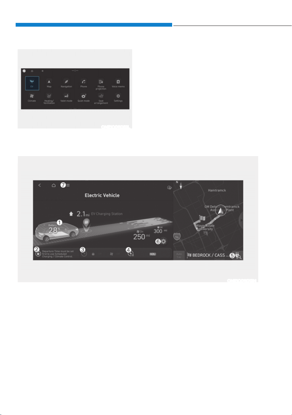
EV Mode Screen
ONE1Q011013N
EV MODE
ONE1Q011052L
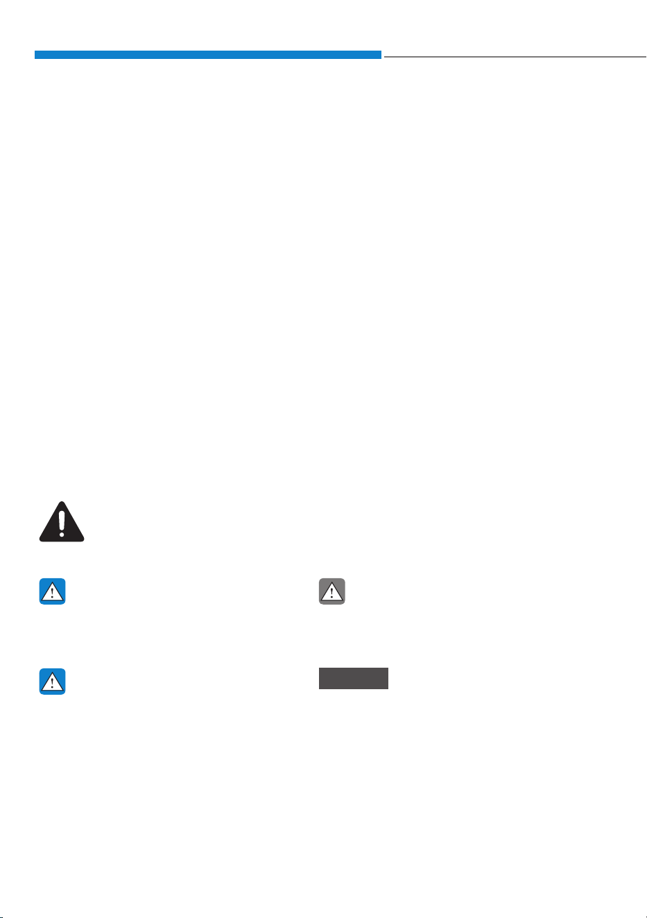
If you select the “EV” menu at the home
screen you can enter EV mode.
For detailed information, refer to the
separately supplied infotainment
system manual.
1. Energy Information
2. Next Departure
3. Charging and Climate
4. Vehicle to Load (V2L)
5. Nearby Stations
6. EV Settings
7. Menu
01
1-11
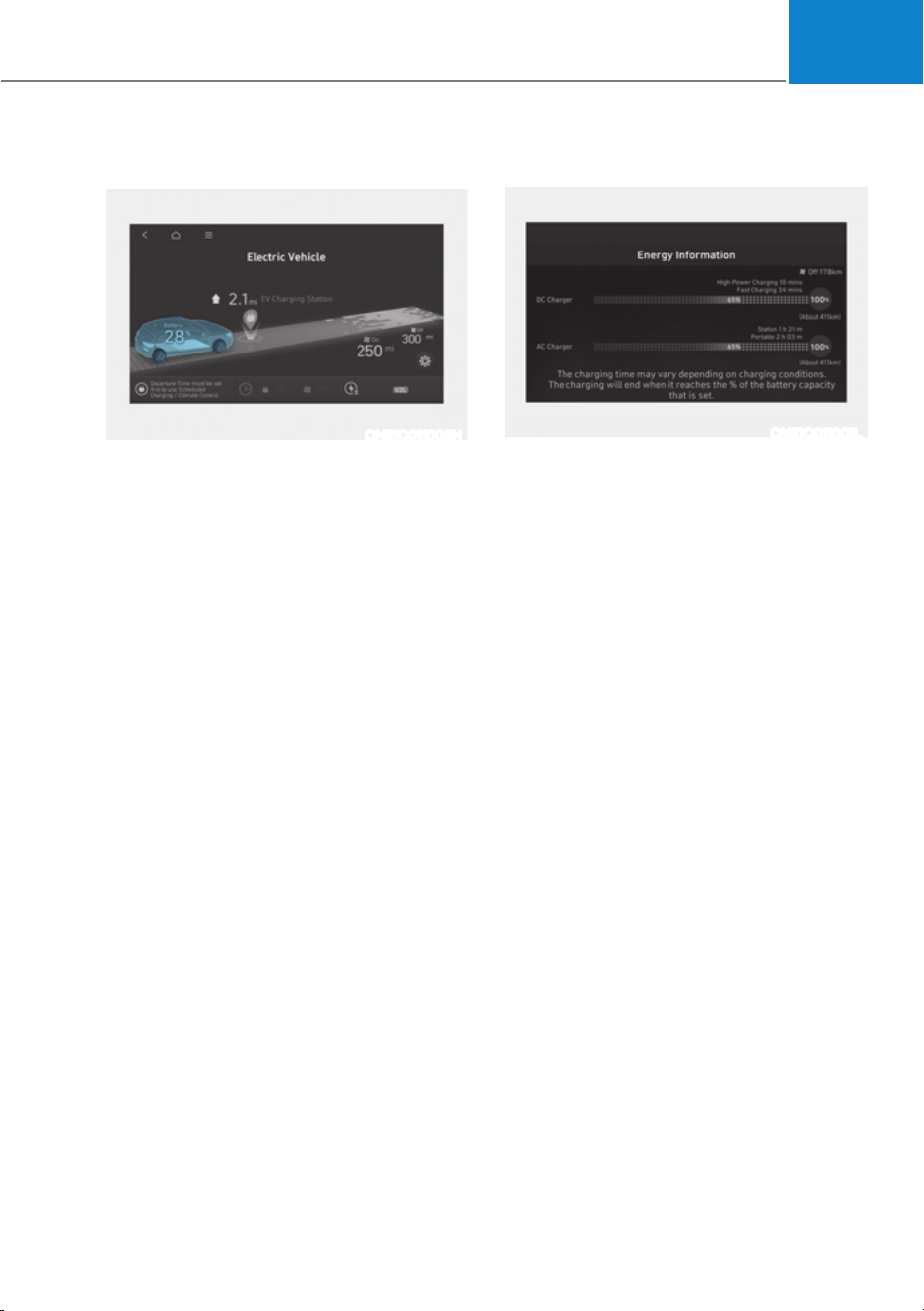
Energy Information
ONE1Q011006N
6HOHFWœ(9Ɵ9HKLFOHLPDJHŔRQWKH
screen.
You can check battery information and
energy consumption.
Battery information
ONE1Q011001L
You can check the reachable range, total
battery power remaining, and expected
charging time for each charge type.
ś The distance to empty is calculated
based on the real-time electric energy
efficiency while driving. The distance
may change if the driving pattern
changes.
ś The distance to empty may vary
according to the change of the driving
pattern even if the same target battery
charge level is set.
Foreword / Starting your Electric vehicle
1-12
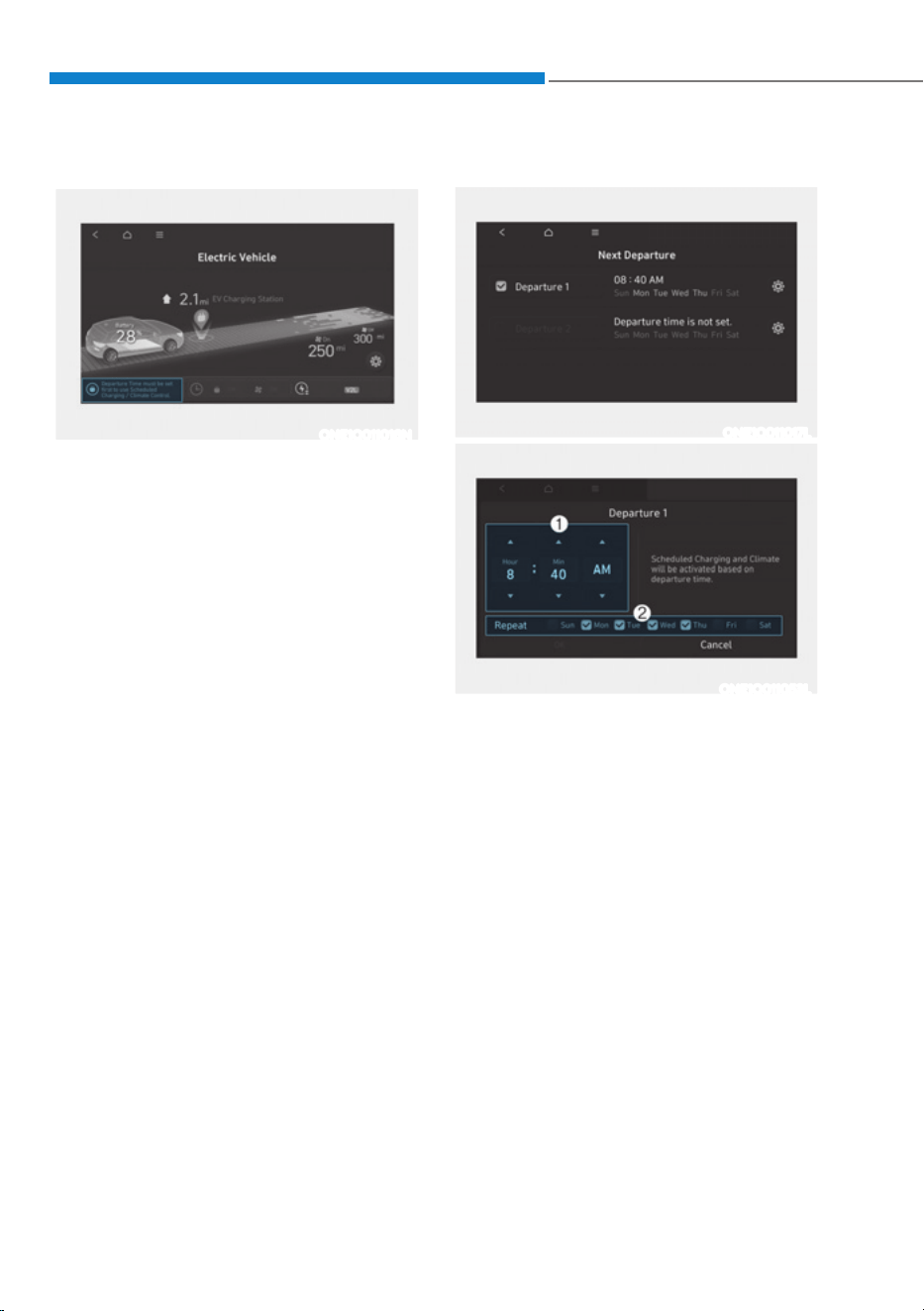
Next Departure
ONE1Q011016N
6HOHFWœ(9Ɵ1H[W'HSDUWXUHŔRQWKH
screen. You can set the date and time
of when to charge the battery, climate
control temperature, and other various
functions.
Departure time
ONE1Q011017L
ONE1Q011053L
1. Set anticipated departure time for
scheduled charging and target
temperature.
2. Select the day of the week to activate
scheduled charging and target
temperature for departure time.
01
1-13
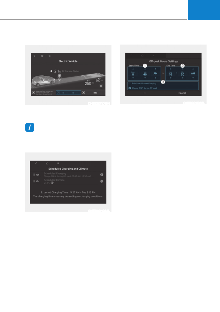
Charging and Climate
ONE1Q011019N
6HOHFWœ(9Ɵ&KDUJLQJDQG&OLPDWHŔRQ
the screen.
Information
Vehicle must be connected with the
charging connector at the time pre-
scheduled time for the scheduled charging.
ONE1Q011054L
You can set the date and time of when
to charge the battery and the climate
control temperature. Also, you may
select the time to start charging using
the off-peak time setting.
Off-peak time settings
ONE1Q011055L
1. If selected, starts charging only on
the designated off-peak time. If
deselected, starts charging only on
the scheduled time.
2. Set the most inexpensive time to
complete charging.
- Off-peak tariffs prioritized: If
selected, starts charging at off-peak
time(may keep on charging pass
off-peak time to charge 100%).
- Charge only during Off-peak: If
selected, charges only within off-
peak time(may not charge 100%).
Foreword / Starting your Electric vehicle
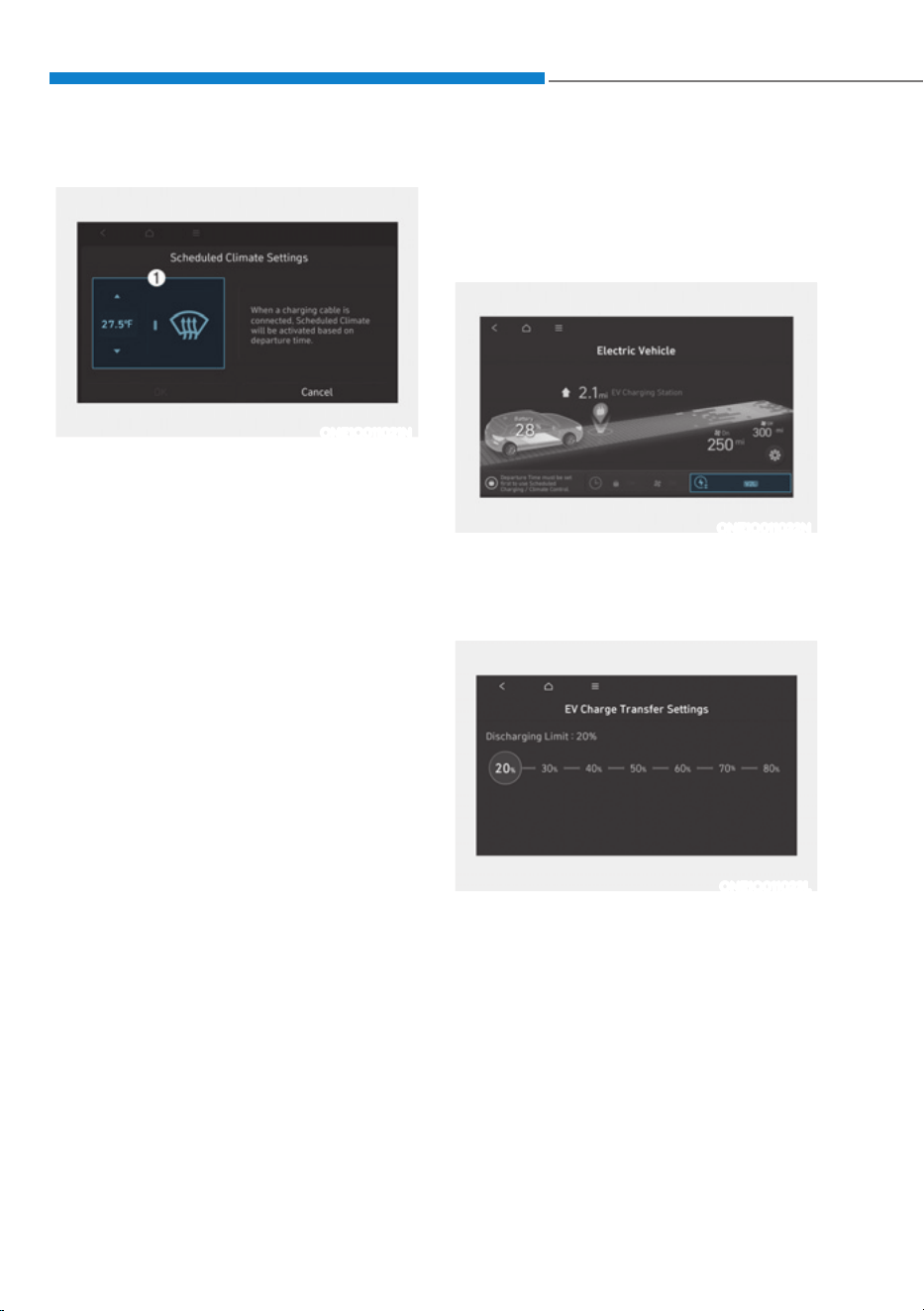
1-14
Target temperature settings
ONE1Q011021N
1. Set target temperature.
- If the target temperature (1) is set
with the cable connected, the cabin
temperature will be adjusted to the
target temperature at departure
time (without loss of high voltage
battery charging level). In cold
weather, preschedule heating
helps enhance electric vehicle
performance by heating the vehicle
in advance.
Vehicle to Load (V2L) (if
equipped)
V2L is the system that provides AC power
using the high voltage battery for driving
to operate several electronical products.
ONE1Q011022N
6HOHFWœ(9Ɵ9HKLFOHWR/RDG9/ŔRQWKH
screen.
You can set the battery discharging limit
for high voltage battery for driving.
ONE1Q011023L
If the vehicle reaches to the limit, it
automatically cut supply of electricity.
01
1-15
Energy information
6HOHFWœ(9Ɵ9HKLFOHLPDJHŔRQWKH
screen.
You can check battery discharging level.
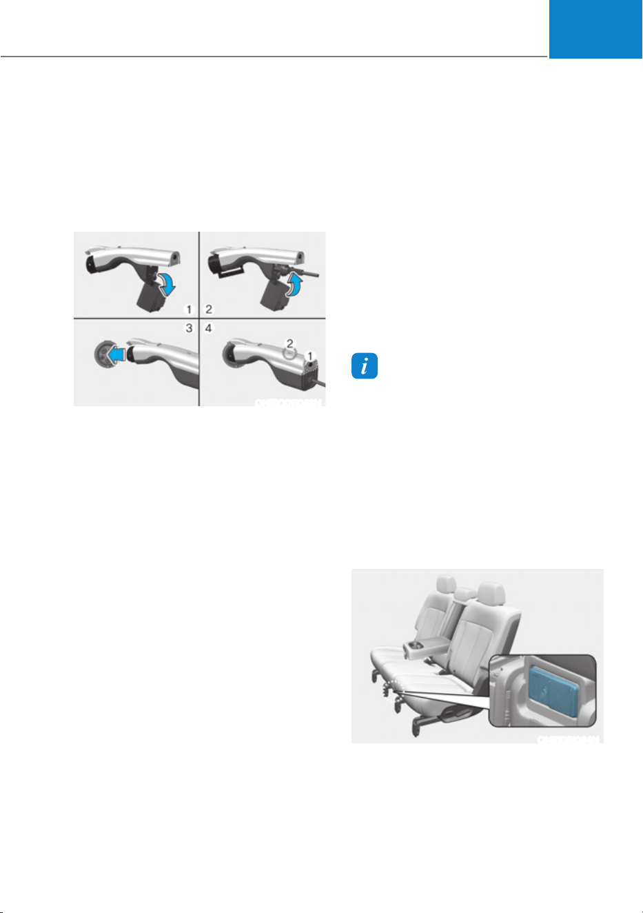
How to connect
Outdoor
ONE1Q011063N
1. Open the cover of the V2L connector.
2. Close the cover after connecting
home appliances and electronical
products to the power outlet.
3. Connect the V2L connector to the
charging inlet on the vehicle.
4. Press the switch (1) of the V2L
connector and check whether the
light (2) is on or off. The light (2) may
not turn on normally when:
- See the battery discharging limit
for high voltage battery for driving
in ‘Electricity Use’ menu on the
screen. If it is higher than the
current amounts of high voltage
battery, the light (2) does not turn
on.
- Check whether the light of V2L
connector or indoor power outlet
turns on or not.
- If the warning message for V2L
appears on the cluster, refer to the
message entirely.
- If V2L does not operate previously
when you connects another home
appliances, have your vehicle
inspected by an authorized
HYUNDAI dealer.
5. Press the switch (1) to turn off the light
(2) the the V2L will be off. You can
disconnect the V2 connector when
the light (2) turns off or the charging
connecter lock is deactivated pressing
the door unlock button on the smart
key.
Information
Please connect the V2L connector to the
charging inlet within 60 seconds after the
charging cover opens. To prevent theft
after connecting, it is changed to auto lock
automatically so that it is impossible to
separate.
When using V2L, cancel the scheduled air
conditioning setting. V2L operation may
be blocked by scheduled air conditioning
operation conditions.
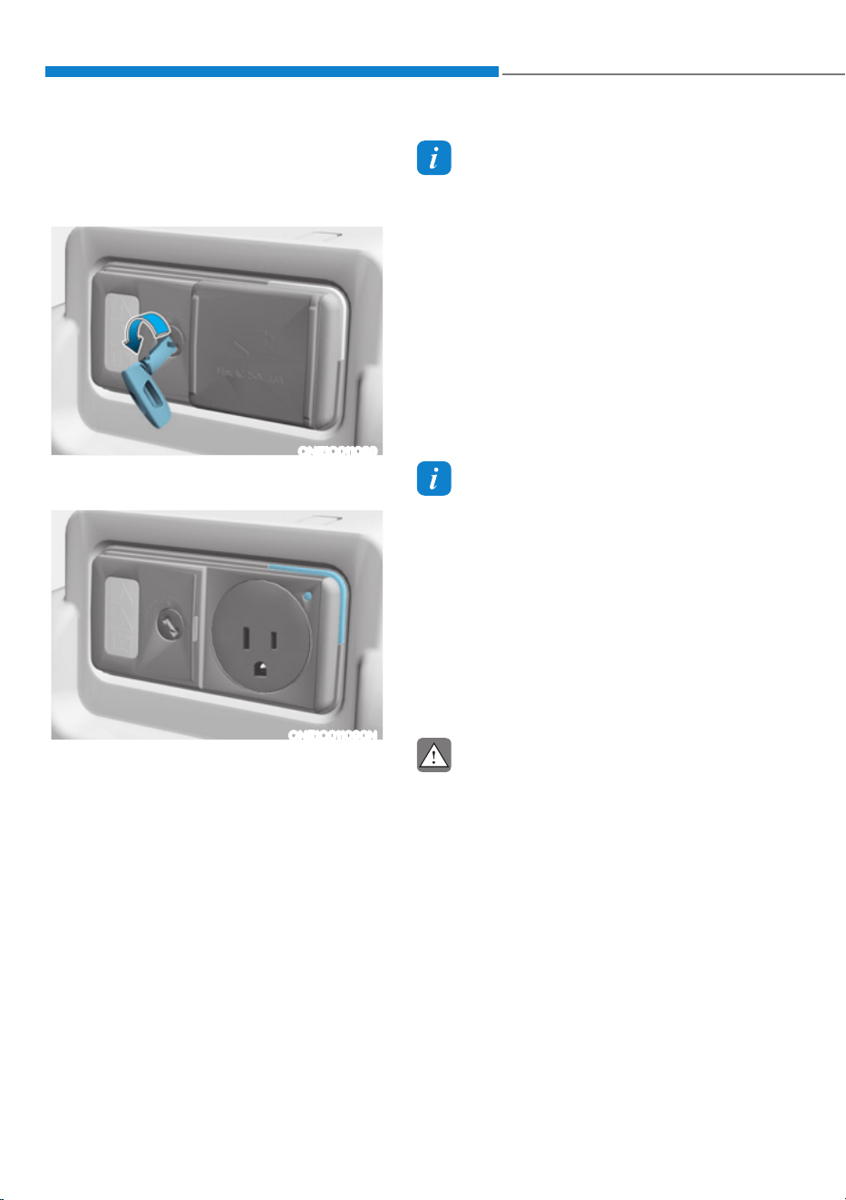
Indoor
ONE1051084N
Foreword / Starting your Electric vehicle
1-16
1. Connect to the power outlet located
in bottom of the rear seat with the
Vehicle Stop/Start button in the ON
position.
ONE1Q011089
2. Use the smart key to unlock the power
outlet cover.
ONE1Q011090N
3. Check the operation status through
the front indicator of the power outlet.
- Blue: Standby
- Red: No power supply even the
power outlet is connected
- Green: Normal power supply
through the normal connection of
the power outlet.
Information
When the used power is exceeded due to
overload, the use of V2L is stopped and
the “V2L function is stopped due to excess
power“ message appears in the cluster.
Disconnect the electronic product to reset
the V2L and follow as below.
- After removing the outdoor V2L
connector, it can be used again by
reconnecting it.
- When using only indoor V2L with the
vehicle ON, if V2L is terminated due
to overload, it can be used only after
restarting.
Information
ś V2L discharging mode will shut off if
the vehicle is off using indoor V2L on
the vehicle state of ON.
ś Opening the charging door or
connecting the V2L connector to the
charging inlet, the V2L discharging
mode will shut off. If you want to
use the indoor and outdoor V2L
simultaneously, firstly connect the V2L
connector to the charging inlet and use
the indoor V2L.
CAUTION
ś Be well-informed of the manual to
prevent accidents.
ś The V2L discharging mode is
blocked automatically in case of
overheating. (When the discharging
mode is blocked, check whether
the V2L connector or power plug
is contaminated, worn, corroded
or broken or the home appliance
capacity is over 16 A. If the
temperature falls to proper level
after it is left unattended, you can
use it again. Use proper home
appliances.)

01
1-17
ś Do not remodel or disassemble
the provided V2L connector. The
failure caused by remodeling or
disassembling is not covered by the
warrant.
ś Do not drop the V2L connector or
give a strong impact to it.
ś Do not place objects on the V2L
connector.
ś Be sure to disconnect the V2L
connector from the vehicle when you
are finished using V2L.
ś When the high voltage battery
charge reaches the set discharging
limit(%), the operation stops, and
a warning message is displayed on
the instrument panel. If you want
V2L operation, set the discharging
limit(%) lower than the current
battery charge.
ś When using various electric
products, use them below the
maximum power capacity that can
be supplied by the vehicle.
ś If you use an electrical appliance
that exceeds the maximum power
capacity that the vehicle can supply,
the operation will stop and a warning
message will be displayed on the
instrument panel. Make sure the
total power consumption of the
electrical appliance you use exceeds
the V2L maximum power capacity.
ś Some of the electric products may
not operate normally even if the
product has power consumption less
than the maximum power capacity
provided by the vehicle.
- Electrical products that require
high power during initial
operation.
- Measuring devices that need to
process accurate data.
- Electric products sensitive to
inverter type AC power supply
(Inverter: A device that converts
DC power into AC power)
ś Do not use products that require
a continuous power supply,
such as medical equipment. The
power supply may be interrupted
depending on the vehicle’s
condition.
ś Only use home appliances under 16
ampere.
ś Put the power plug fully and use
the qualified plug that meets the
standard. If you use worn, corroded
or broken plug or improper plug, it
might be a cause of malfunction.
ś Use the power plug with ground
connection.
ś Do not use high power home
appliances such as air conditioner,
washing machine or dryer.
ś Do not hang the home appliances on
to the wire.
ś For various devices connected to
an power outlet, use only products
that have obtained national
safety certification. For usage and
precautions, refer to the manual of
the device. (Electrical appliances,
multi-outlets, cord extension cables,
etc.)
ś For devices used outdoors in
a vehicle, use a product with a
waterproof function or use it in a
waterproof environment. Do not use
in environments with rain or high
humidity. (Electrical appliances,
multi-outlets, cord extension cables,
etc.)
ś If there is a risk of lightning, do not
use the V2L function outside the
vehicle.
ś Do not connect multiple portable
multi-outlets.
ś When using an extension cable, if
the cable is twisted or overlapped by
itself may cause a fire. Be sure to use
the cable without twisting it.

Foreword / Starting your Electric vehicle
1-18
ś When using the vehicle’s outdoor
V2L connector, power is also
supplied to the vehicle’s indoor
power outlet. Unplug electrical
appliances that are not in use from
the indoor power outlet.
ś When using the V2L, the cooling fan
in the vehicle motor compartment
can operate automatically even if the
vehicle is turned off. Do not put your
hand near the cooling fan in the V2L
operating state.
WARNING
ś Do not touch the V2L connector of
the terminal of the vehicle charging
inlet.
ś Do not put metal objects to the V2L
connector or charging inlet. It might
be a cause of electric shock.
ś Do not touch the V2L connector,
charging inlet or power plug with
a wet hand. It might be a cause of
electric shock. Please handle with a
dry hand all the time.
ś Confirm whether there is foreign
substance such as water or dust on
the V2L connector, charging inlet or
power plug before connecting. If you
connect it with foreign substances,
it may be a cause of fire or electric
shock.
ś Do not remodel or disassemble the
V2L connector. There is a risk of fire,
electric shock or injury.
ś When the power plug is connected or
disconnected to the V2L connector
or open or close the connector
cover of the V2L, be careful not to be
scratched on the hand.
ś Do not charge in the following
conditions. The accident might
occur.
- The V2L connector, charging inlet,
power plug or cable is damaged,
corroded or rusted.
- The connection part is loose.
ś Do not use if the sheath of home
appliance cables is damaged or
broken. There is a risk of fire, electric
shock or injury.
ś Never use an electric heating
appliance like iron, coffee pot, and
toaster in the vehicle. It may cause a
fire and injury.
LCD display messages
ONE1Q011077L
V2L has ended. Battery level has reached
the set value
When the high voltage battery level
reaches the discharging limit set level,
the V2L will stop and the warning will
be displayed. If you want to use the V2L
continuously, make the discharging limit
set level lower than the present battery
level.
01
1-19
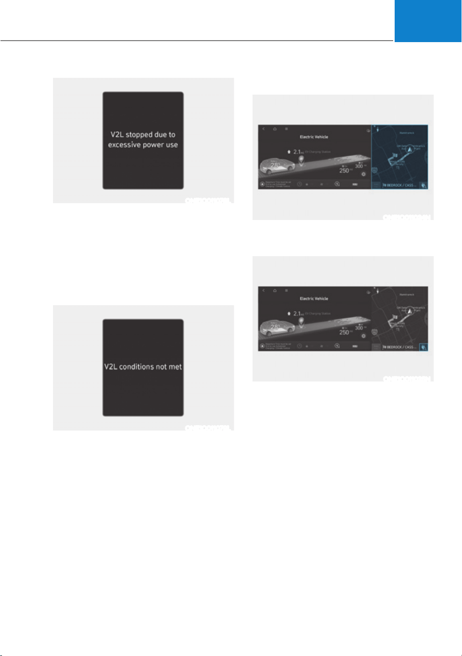
ONE1Q011078L
V2L stopped due to excessive power use
If you use an electrical appliance that
exceeds the maximum power output the
vehicle can supply, it will stop working
and display a warning message. Make
sure that the total power consumption of
your electrical appliance exceeds the V2L
maximum power output.
ONE1Q011079L
V2L conditions not met
If V2L is interrupted for any of the
following reasons, a warning message is
displayed.
ś V2L connector switch off
ś V2L connector overheating
ś Opening the charging door while
using the V2L indoor outlet
Make sure there are no problems with
the V2L connector and the vehicle indoor
outlet.
Nearby Stations
ONE1Q011024N
6HOHFWœ(9Ɵ0DSŔRQWKHVFUHHQ6WDWLRQV
around the current location are searched.
ONE1Q011025N
Select ‘Search for charging stations’ on
the screen.
Foreword / Starting your Electric vehicle
1-20
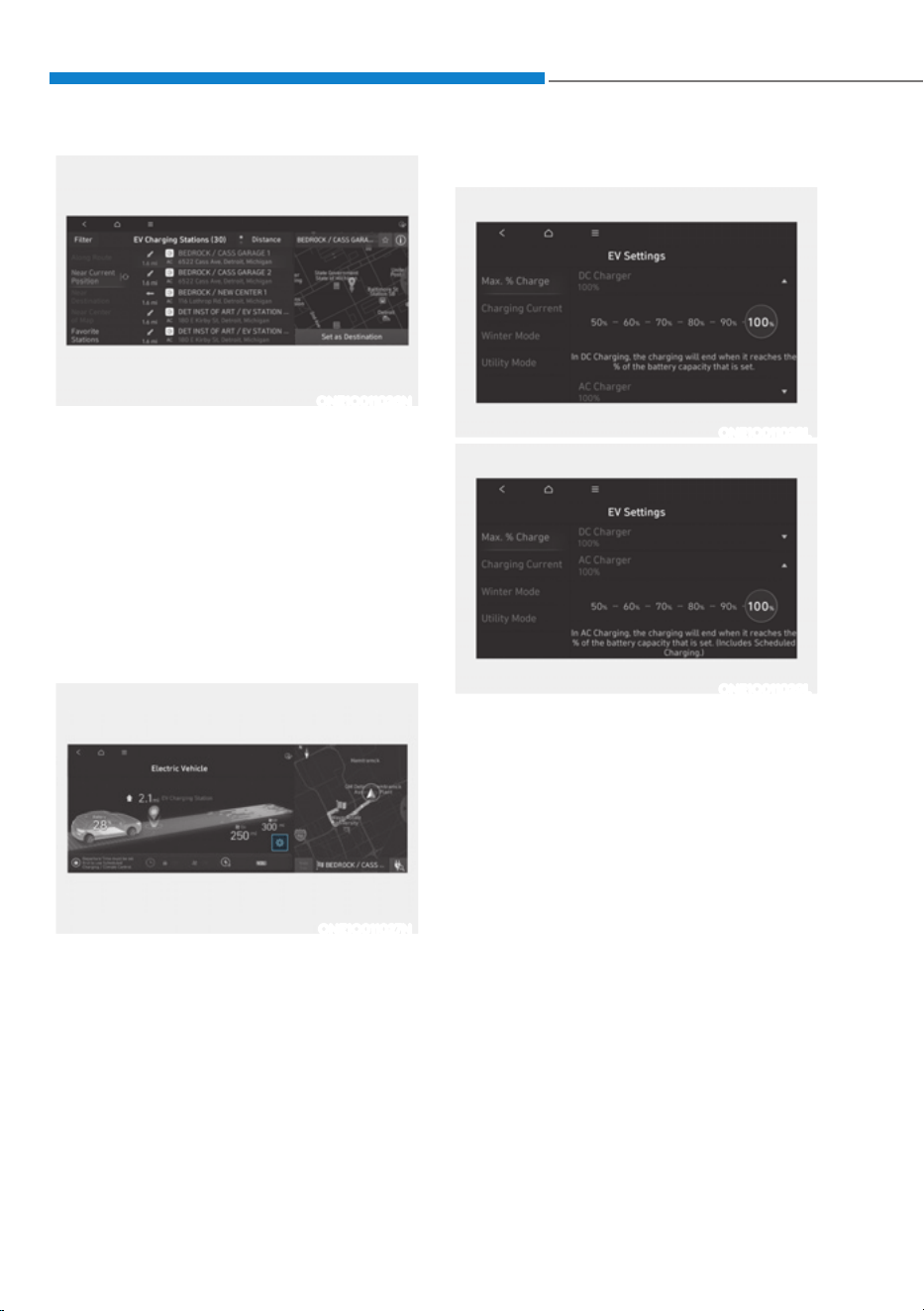
ONE1Q011026N
Around the course, around the current
site, around the selected destination
or charging stations of interest will be
searched. If you choose the charging
station, the detailed information will be
provided.
For more detailed information, please
refer to the separately supplied
infotainment system manual.
EV Settings
ONE1Q011027N
6HOHFWœ(9Ɵ(96HWWLQJVŔRQWKHVFUHHQ
You can set the charging limit, charging
current, winter mode and utility mode
functions.
Charging limit (Max. % Charge)
ONE1Q011028L
ONE1Q011029L
ś The target battery charge level can
be selected when charged with AC
charger or DC charger.
ś The charging level can be changed by
10%.
ś If the target battery charge level is
lower than the high voltage battery
charge level, the battery will not be
charged.

01
1-21
Charging current
ONE1Q011030L
ś You can adjust the charging
current for an AC charger. Select an
appropriate charging current.
ś If the charging process does not
start or abruptly stops in the middle,
reselect another proper current and
re-try charging the vehicle.
ś Charging time varies depending on
which charging current is selected.
Winter Mode
ONE1Q011031L
You can select or deselect the Winter
mode.
The Winter mode is efficient during
the winter time when the high voltage
battery temperature is low.
This mode is recommended to improve
driving and DC charging performances
during winter by raising the battery
temperature to an adequate level.
However, the driving distance may be
reduced as the energy is required to
increase battery temperature.
Also, if the battery temperature is low
during driving or when scheduled air
conditioner/heater is activated, this
mode is operated to improve driving
performance.
However, the mode is not operated to
ensure driving distance when the battery
level is low.
Information
This mode is available for the vehicles
equipped with the battery heater.
Foreword / Starting your Electric vehicle
1-22
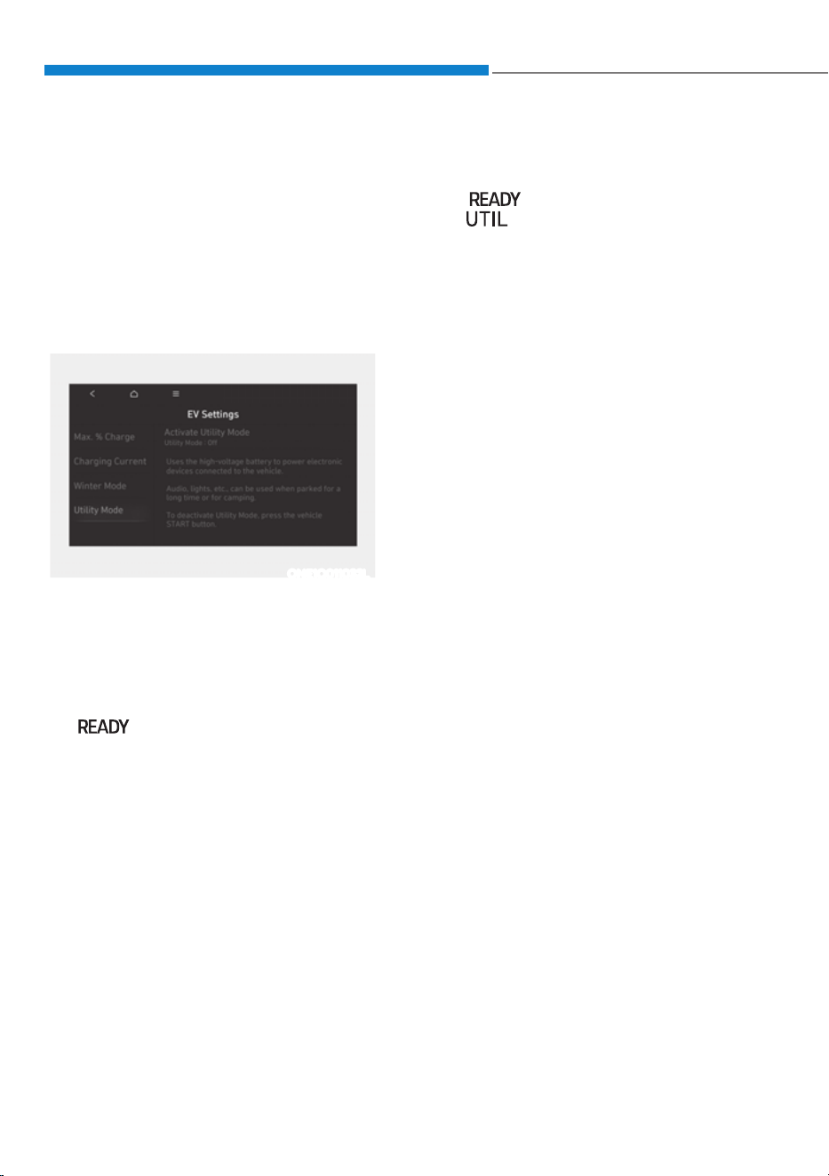
Utility Mode
The high voltage battery is used instead
of the 12V auxiliary battery for operating
the convenient features of the vehicle.
When driving is not necessary such as
while camping or when stopping the
vehicle for a long time, it is possible to
use the electrical devices (audio, lights,
air conditioner, heater, etc.) for long
hours.
ONE1Q011032L
System Setting and Activation
System setting
The driver can activate the Utility mode
function when the following conditions
are satisfied.
ś The vehicle is in the ready
(
) mode and the gear is shifted
to P (Park).
ś The EPB (Electronic Parking Brake) is
not a malfunction.
ś œ(9VHWWLQJVƟ8WLOLW\PRGHŔLVVHOHFWHG
on the infotainment system screen.
System Activation
When the system is activated:
ś The (
) indicator will turn off, and
the (
) indicator will illuminate on
the cluster and the EPB is applied.
ś All electric devices are usable but the
vehicle cannot be driven.
ś The EPB can be cancelled by pressing
the EPB switch.
Gear cannot be shifted out of P (Park).
If a shift attempt is made, a message
“Shifting conditions not met” will be
displayed on the infotainment system
screen.
System Deactivation
The Utility mode can be deactivated by
pressing the START/STOP button to the
OFF position. The function cannot be
deactivated from the EV settings.

01
1-23
CHARGE TYPES FOR ELECTRIC VEHICLE
Charging Information
ś AC Charge: The electric vehicle is charged by plugging into a AC charger installed at
your home or a public charging station. (For further details, refer to the ‘AC Charge’.)
ś DC Charge: You can charge at high speeds at public charging stations. Refer to the
respective company’s manual that is provided for each DC charger type.
Battery performance and durability can deteriorate if the DC charger is used
constantly.
Use of DC charge should be minimized in order to help prolong high voltage battery
life.
ś Portable Charge: The Electric vehicle can be charged by using household electricity.
The electrical outlet at your home must comply with regulations and can safely
accommodate the Voltage / Current (Amps) / Power (Watts) ratings specified on the
portable charge.
Charging Time Information
Charging type Standard battery type Extended battery type
AC charge
Takes approx. 5 hours 50
minutes at room temperature
when charged to 100%
Takes approx. 7 hours 10 minutes
at room temperature when
charged to 100%.
DC charge
350 kW
charger
Takes about 18 minutes at
room temperature when
charged from 10% to 80%. Can
be charged to 100%.
Takes about 18 minutes at room
temperature when charged from
10% to 80%. Can be charged to
100%.
50 kW
charger
Takes about 63 minutes at
room temperature when
charged from 10% to 80%. Can
be charged to 100%.
Takes about 73 minutes at room
temperature when charged from
10% to 80%. Can be charged to
100%.
Portable charge
Takes approx. 51 hours at room
temperature when charged to
100%.
Takes approx. 68 hours at room
temperature when charged to
100%.
Information
Depending on the condition and durability of the high voltage battery, charger
specifications, and ambient temperature, the time required for charging the high voltage
battery may vary.
Foreword / Starting your Electric vehicle
1-24
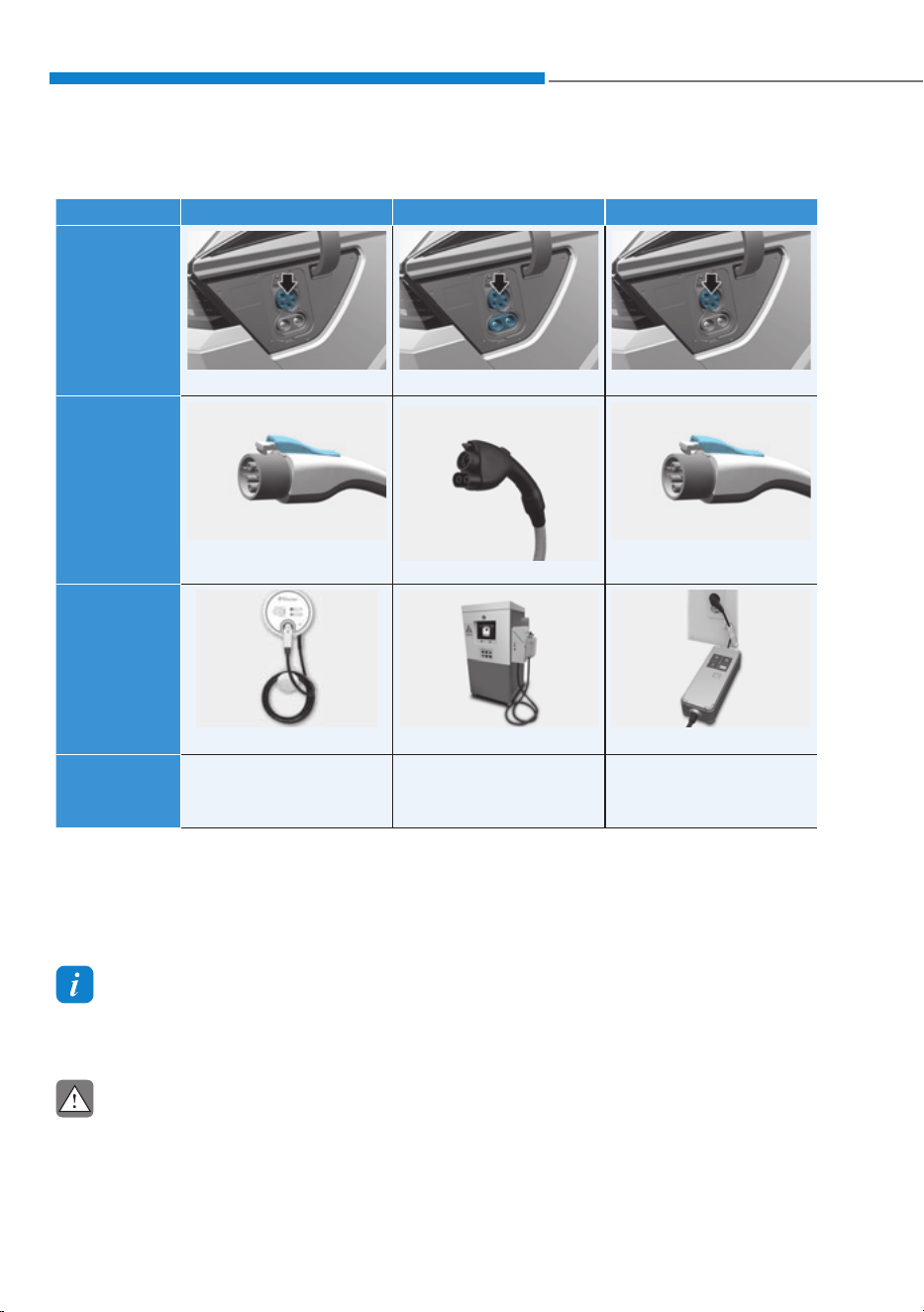
Charging Types
Category AC Charge DC Charge Portable Charge
Charging
Inlet
(Vehicle)
ONE1Q011036 ONE1Q011037 ONE1Q011036
Charging
Connector
ONE1Q011083
OAEEQ016079N
ONE1Q011083
Charging
Outlet
OLFP0Q4057N OAEEQ016023 ONX4EPHQ011019L
How to
Charge
Use AC charger
installed at home or
public charging station
Use the DC charger at
public charging station
Use household current
ś Depending on the condition and durability of the high voltage battery, charger
specifications, and ambient temperature, the time required for charging the high
voltage battery may vary.
ś Actual charger image and charging method may vary in accordance with the
charger manufacturer.
Information
Type 3R, when mating with outlets.
Additional Type 3R enclosure should be provided in the end installation.
CAUTION
ś Risk of electric shock, do not disconnect under load.
ś Suitable for use on a circuit capable of delivering not more than 5000 rms
symmetrical amperes, 250 volts maximum
01
1-25
CHARGE INDICATOR LAMP FOR ELECTRIC VEHICLE
When charging the high voltage battery, the charge level can be checked from outside
the vehicle.
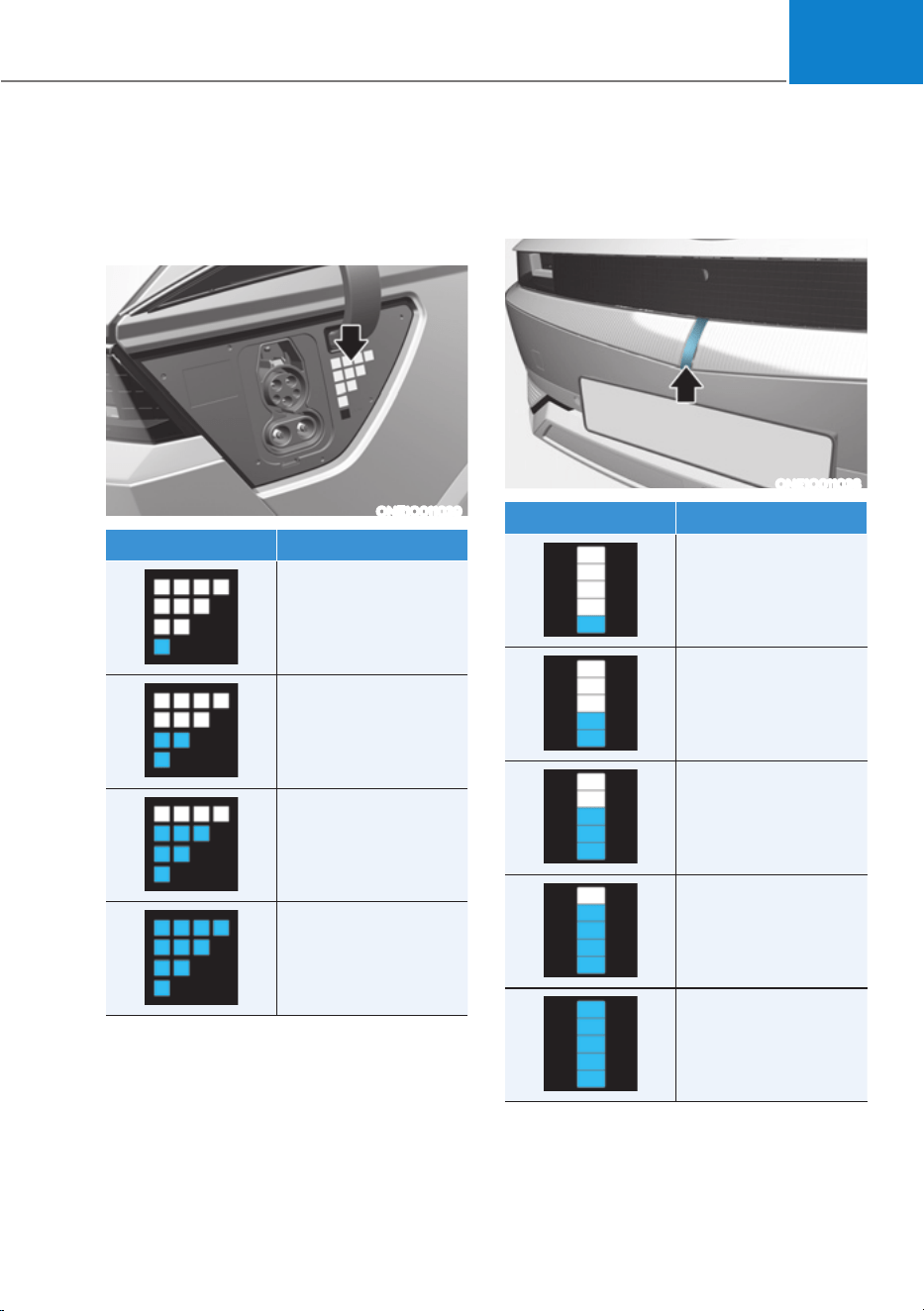
Charging Status
Electric charging door
ONE1Q011039
Lamp status Battery SOC [%]
0 ~ 24
25 ~ 49
50 ~ 74
75 ~ 100
Front Center Bumper (if equipped)
ONE1Q011038
Lamp status Battery SOC [%]
0 ~ 20
21 ~ 40
41 ~ 60
61 ~ 80
81 ~ 100
Foreword / Starting your Electric vehicle
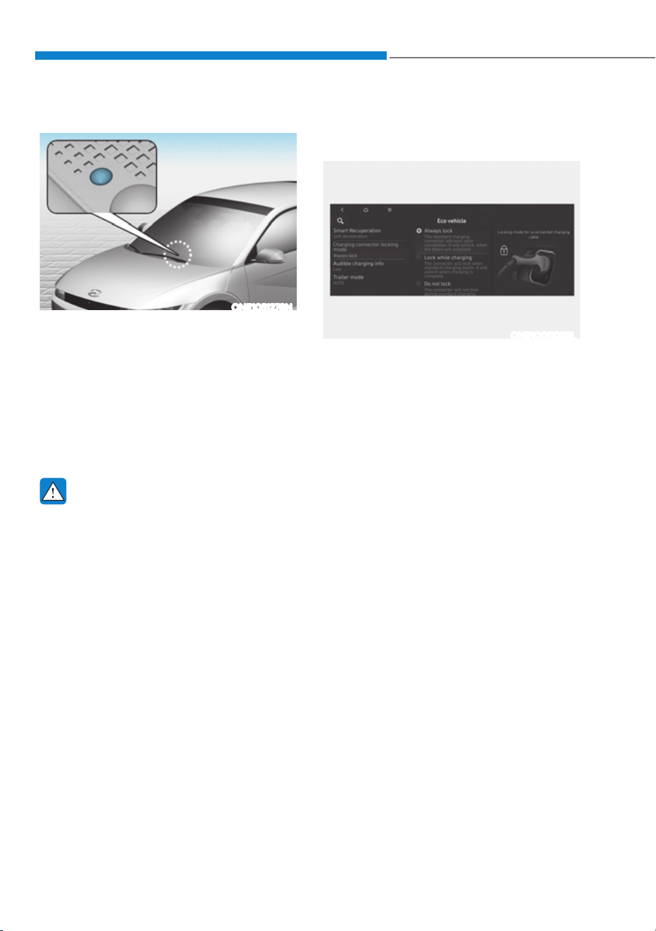
1-26
High voltage indicator
ONE1051278N
The high voltage indicator is located on
top of the crash pad.
When the 12 volt auxiliary battery is
discharged, it is charged from the high
voltage battery of the vehicle.
When the high voltage electricity flow
in the vehicle, the color of the indicator
changes to amber and turns off after
charging is finished.
WARNING
When the function is activating, the
Charging Indicator Lamp will turn on
and high voltage electricity will be
flowing in the vehicle. Do not touch
the high voltage electric wire (orange),
connector, and all electric components
and devices. This may cause electric
shock and lead to injuries. Also, do not
modify your vehicle in any way. This
may affect your vehicle performance
and lead to an accident.
CHARGING CONNECTOR
LOCK
Locking Charging Cable
ONE1Q011092L
You may select when the charging
connector can be locked and unlocked in
the charging inlet.
6HOHFWœ6HWWLQJVƟ(&29HKLFOHƟ
Charging Connector Locking Mode’ in
the infotainment.
01
1-27
Scheduled Charging
(if equipped)
ś You can set-up a charging
schedule for your vehicle using the
Infotainment system or Blue Link
application.
Refer to the infotainment system
manual or the Blue Link application
for detailed information about setting
scheduled charging.
ś Scheduled charging can only be
done when using a AC charger or
the portable charger (ICCB: In-Cable
Control Box).
ONE1Q011039
ś When scheduled charging is set
and the AC charger or the portable
charger (ICCB: In-Cable Control
Box) is connected for charging, the
indicator lamp blinks from the first
level to the last for about 3 minutes
to indicate that scheduled charging
is set.
ś When scheduled charging is set,
charging is not initiated immediately
when the AC charger or portable
charger (ICCB: In-Cable Control
Box) is connected. When immediate
charging is required, press the
charging door open button in the
smart key for 2 seconds or deactivate
the scheduled charge setting with
the infotainment system or Blue Link
application.
Refer to “AC Charge (Station) or Trickle
Charge” for details about connecting
the AC charger and the portable charger
(ICCB: In-Cable Control Box).
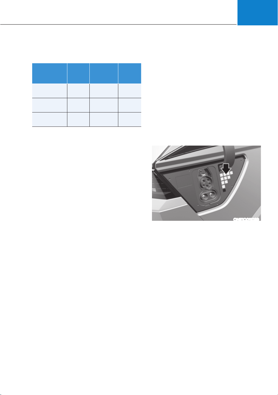
When the Charging Connector Is
Locked
Always
lock
Lock
while
charging
Do not
lock
Before
charging
OXX
While
charging
OOX
Finished
charging
OXX
ś ‘Always lock’ mode :
The connector locks when the
charging connector is plugged into
the charging inlet. The connector is
locked until all doors are unlocked by
the driver. This mode can be used to
prevent charging cable theft.
- If the charging connector is
unlocked when all doors are
unlocked, but the charging cable
is not disconnected within 15 sec-
onds, the connector will be auto-
matically locked again.
- If the charging connector is
unlocked when all doors are
unlocked, but all doors are locked
again, immediately, the connector
will be automatically locked again.
ś ‘Lock while charging’ mode :
The connector locks when charg- ing
starts. The connector unlocks when
charging is complete. This mode can
be used when charging in a public
charging station.
ś ‘Do not lock’ mode :
The connector unlocks regardless of
the state of charging.
Press the charging connector release
button, disconnect the connector.
Be careful to theft of the charging
cable.
SCHEDULED CHARGING
Foreword / Starting your Electric vehicle
1-28
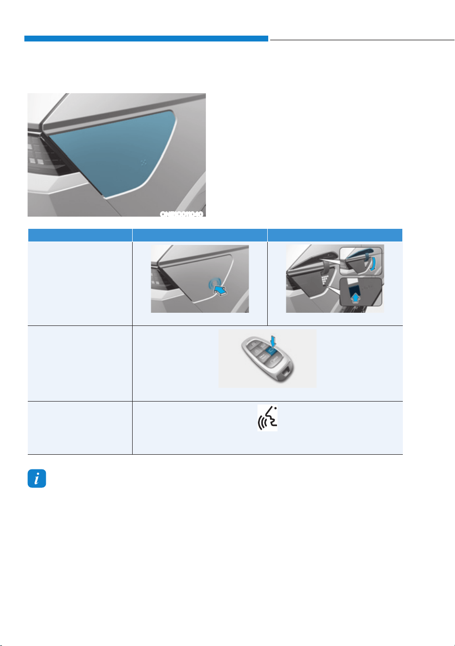
Electric Charging Door
ONE1Q011040
The electric charging door will open and
close as follows.
CHARGING ELECTRIC VEHICLE
Methods Open Close
Touch and Push
ONE1Q011064
ONE1Q011067
Smart Key
ONE1Q011066
Voice Recognition
WNE1-208
(Limited to areas where voice recognition is applied)
Information
ś The charging door automatically closes when:
- The charging connector is disconnected
- The charging procedure has not done for a certain amount of time while the
charging door is opened.
- The gear is in D (drive), N (neutral), or R (Reverse).
ś After replacing battery (12 volt), open and close the charging door once to check that
the charging door automatic opening mechanism is functioning properly.
ś When replacing the charging door, be sure to disconnect the vehicle-side wiring
connector of the charging door module and reconnect it to ensure normal operation of
the charging door.
01
1-29
Charging Precautions
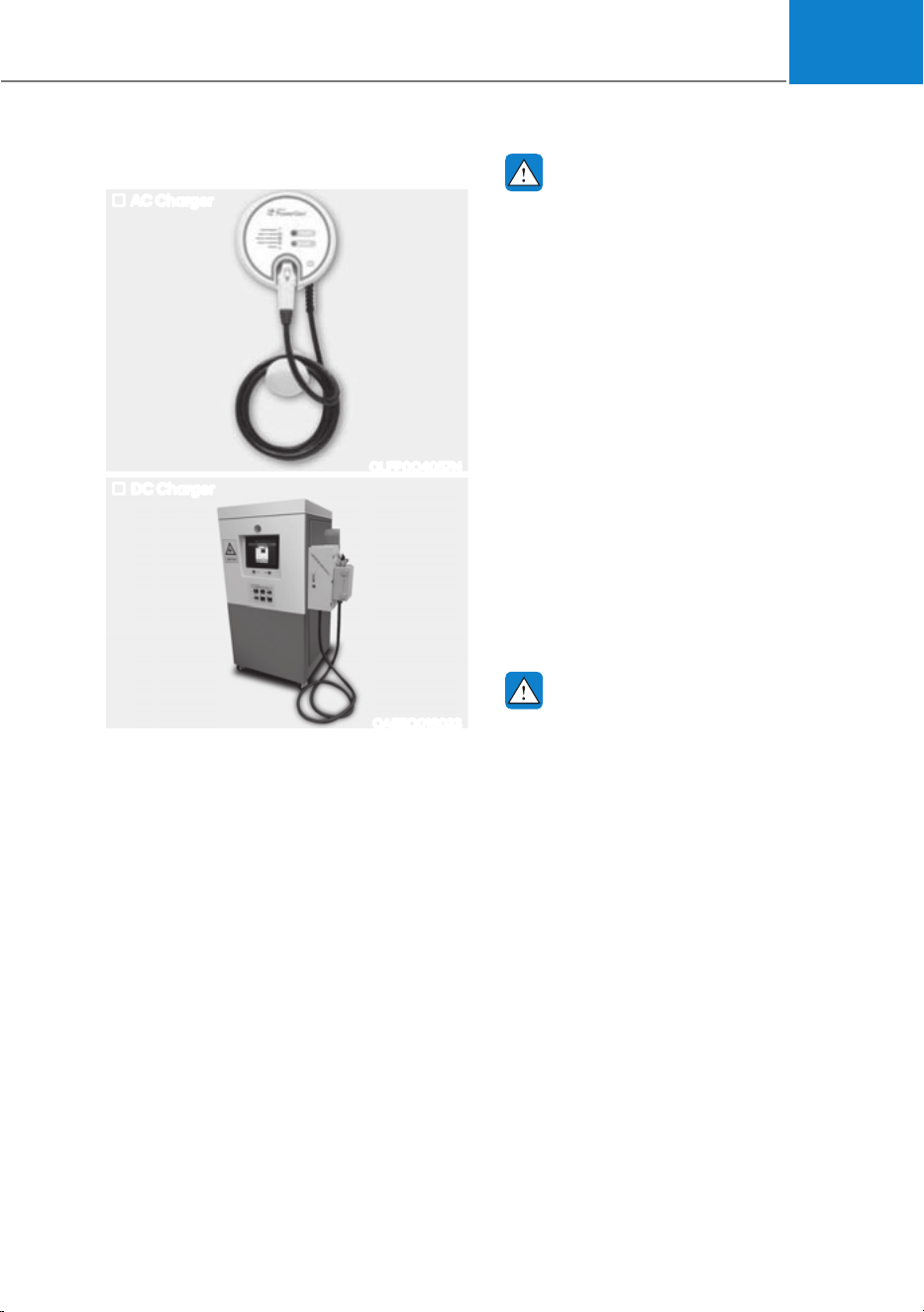
AC Charger
OLFP0Q4057N
DC Charger
OAEEQ016023
Actual charger image and charging
method may vary in accordance with the
charger manufacturer.
WARNING
ś Electromagnetic waves that are
generated from the charger can
seriously impact medical electric
devices such as an implantable
cardiac pacemaker.
When using medical electric devices
such as an implantable cardiac
pacemaker, make sure to ask the
medical team and manufacturer
whether charging your electric
vehicle will impact the operation of
the medical electric devices such as
an implantable cardiac pacemaker.
ś Check to make sure there is no
water or dust on the charging
cable connector and plug before
connecting to the charger and
charging inlet. Connecting while
there is water or dust on the charging
cable connector and plug may cause
a fire or electric shock.
WARNING
ś Be careful not to touch the charging
connector, charging plug, and the
charging inlet when connecting
the cable to the charger and the
charging inlet on the vehicle.
ś Comply with the following in order
to prevent electrical shock when
charging:
- Use a waterproof charger.
- Do not touch the charging
connector and charging plug with
your hands wet, or do not stand in
water or snow while connecting
the charging cable.
- Be careful when there is lightning.
- Be careful when the charging
connector and plug are wet.
Foreword / Starting your Electric vehicle
1-30
WARNING
ś Immediately stop charging when
you find abnormal symptoms (odor,
smoke).
ś Replace the charging cable if the
cable coating is damaged to prevent
electrical shock.
ś When connecting or removing the
charging cable, make sure to hold
the charging connector handle and
charging plug.
If you pull the cable itself (without
using the handle), the internal
wires may be disconnected or get
damaged. This may lead to electric
shock or fire.
CAUTION
ś Always keep the charging connector
and charging plug in clean and
dry condition. Be sure to keep the
charging cable in a condition where
there is no water or moisture.
ś Be sure to use only certified electric
vehicle charger. Using uncertified
charger may cause the damage to
the vehicle.
ś Before charging the battery, turn the
vehicle OFF.
ś When the vehicle is switched OFF
while charging, the cooling fan
inside the motor compartment may
automatically operate. Do not touch
the cooling fan while charging.
ś Be careful not to drop the charging
connector. The charging connector
can be damaged.
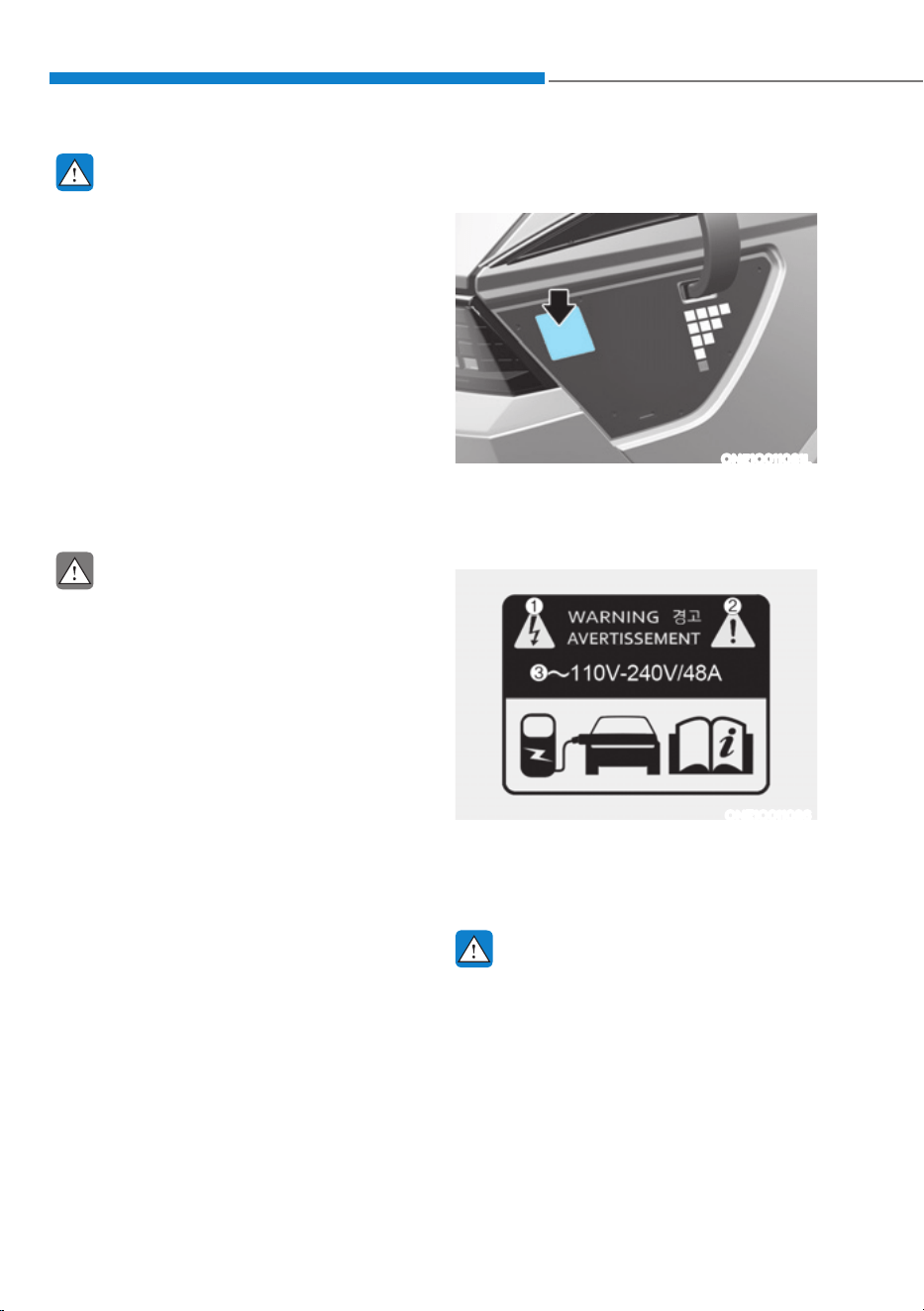
How to Check the Symbol on the
Charging Label
ONE1Q011081L
You can find the charging label when
opening the charging door.
Charging label
ONE1Q011086
1. Warning for high voltage
2. Caution
3. Charging voltage and current
WARNING
Risk of failure, fire, injury, etc., are
expected when using the charging
connector with unmatched symbol.
01
1-31
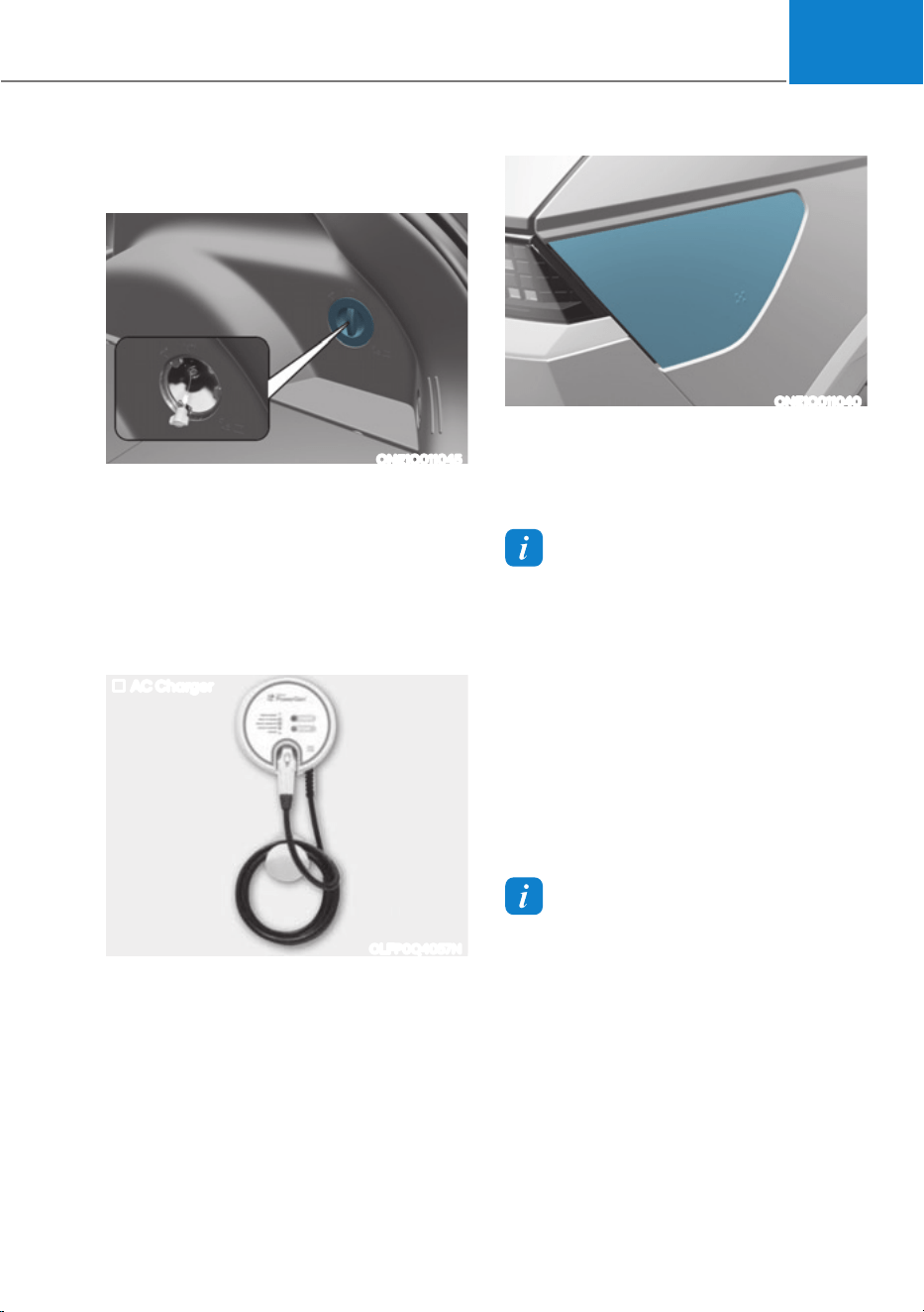
Disconnecting Charging
Connector in Emergency
ONE1Q011045
If the charging connector does not
disconnect from the charging inlet due to
battery discharge and failure of electric
wires, open the liftgate and slightly pull
the emergency cable in the cargo
area. The charging connector will be
disconnected from the charging inlet.
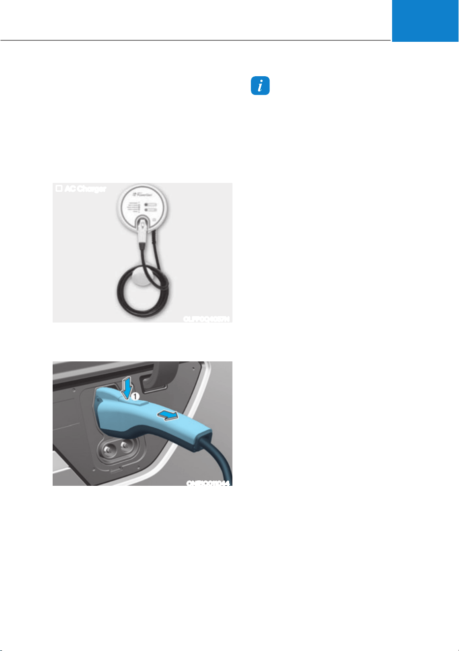
AC Charge
AC Charger
OLFP0Q4057N
Actual charger image and charging
method may vary in accordance with the
charger manufacturer.
How to Connect AC Charger
1. Depress the brake pedal and apply the
parking brake.
2. Turn OFF all switches, shift to P (Park),
and turn OFF the vehicle. If charging is
initiated without the gear in P (Park),
the charging will start after the gear is
automatically shifted to P (Park).
ONE1Q011040
3. Open the charging door.
For more details, refer to ‘Electric
charging door’ in this chapter.
Information
If you cannot open the charging door due
to freezing weather, tap lightly or remove
any ice near the charging door. Do not try
to forcibly open the charging door.
4. Check if there is dust on the charging
connector and charging inlet.
5. Hold the charging connector handle
and connect it to the vehicle charging
inlet. Push the connector all the way
in. If the charging connector and
charging terminal are not connected
properly, this may cause a fire.
Information
Locking Charging Cable
6HOHFWµ6HWWLQJVĺ(&29HKLFOHĺ
Charging Connector Locking Mode’ in
the infotainment. The charging connector
is locked in the inlet at a different period
according to which mode is selected.
ś Always mode : The connector locks
when the charging connector is plugged
into the charging inlet.
ś While charging mode : The connector
locks when charging starts.
For more details, refer to “Locking
Charging Cable” in this chapter.
Foreword / Starting your Electric vehicle
1-32
6. Connect the charging plug to the
electric outlet at a AC charging station
to start charging.
ONE1Q011041
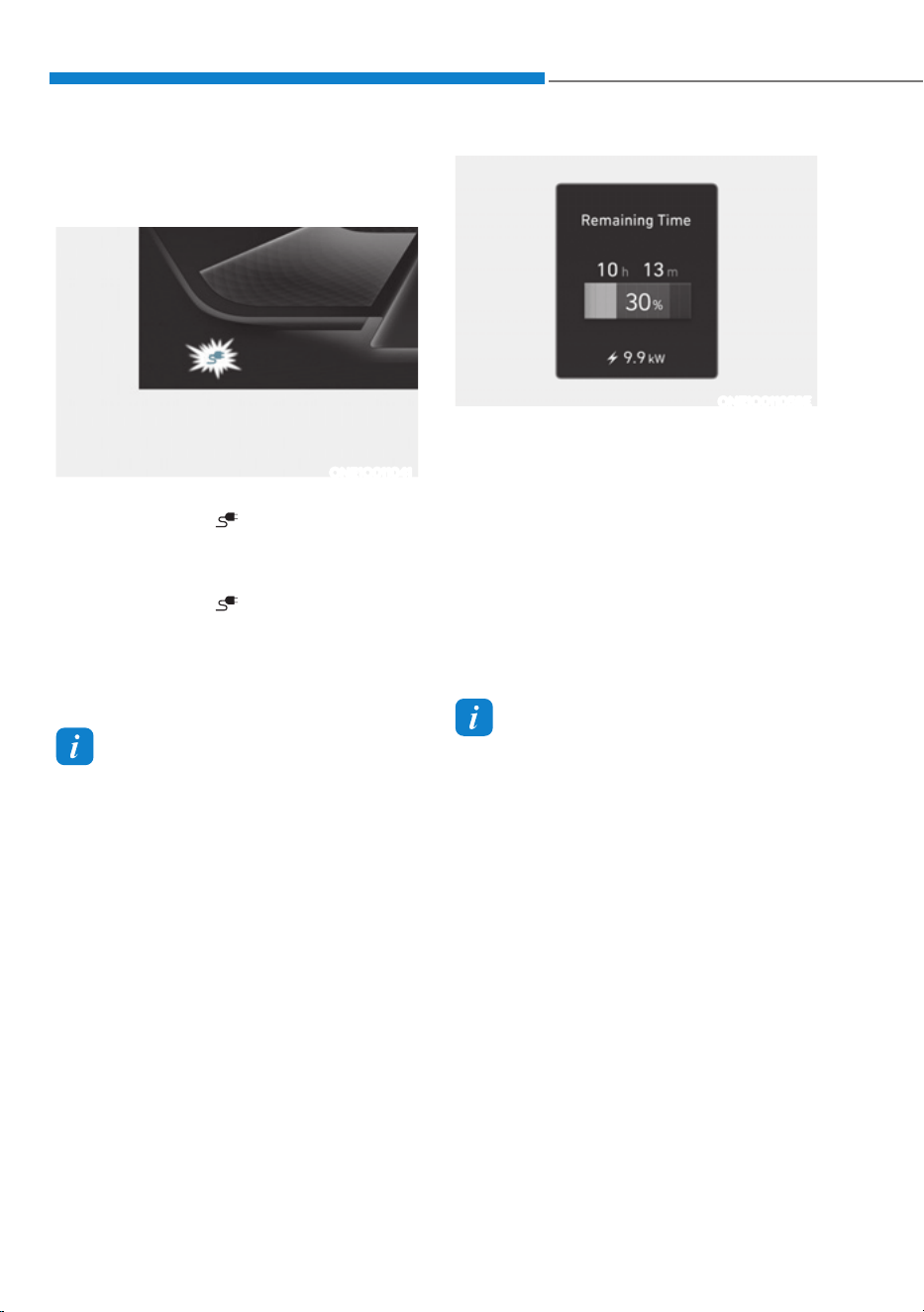
7. Check if the charging connector
indicator light (
) of the high
voltage battery in the instrument
cluster is turned ON. Charging is not
active when the charging connector
indicator light (
) is OFF.
When the charging connector and
charging plug are not connected
properly, reconnect the charging
cable to charge.
Information
ś (YHQWKRXJKFKDUJLQJLVSRVVLEOHZLWK
the Start/Stop button in the ON/START
position, for you safety, start charging
when the Start/Stop button is in the
OFF position and the vehicle shifted to
P (Park). After charging has started,
you can use electrical components such
as the radio by pressing the Start/Stop
button to the ACC or ON position.
ś During AC charging, the radio
reception may be bad.
ś During charging, the gear cannot be
shifted from P (Park) to any other gear.
ONE1Q011058E
8. After charging has started, the
estimated charging time is displayed
on the instrument cluster for about 1
minute.
If you open the driver seat door while
charging, the estimated charging time
is also displayed on the instrument
cluster for about 1 minute. When
scheduled charging or scheduled
air conditioner/heater is set, the
estimated charging time is displayed
as “--” .
Information
Depending on the condition and durability
of the high voltage battery, charger
specifications, and ambient temperature,
the time required for charging the battery
may vary.
01
1-33
Checking Charging Status
When charging the high voltage battery,
the charge level can be checked from
outside the vehicle.
For more details, refer to ‘Charge
Indicator Lamp for Electric Vehicle’ in
this chapter.
How to Disconnect AC Charger
AC Charger
OLFP0Q4057N
1. When charging is complete, remove
the charging plug from the electrical
outlet of the AC charging station.
ONE1Q011044
2. Hold the charging connector handle
and pull it out.
Information
To prevent charging cable theft,
the charging connector cannot be
disconnected from the inlet when the
doors are locked or the charging connector
is in the LOCK mode. Unlock all doors to
disconnect the charging connector from
the inlet.
However, if the vehicle is in the charging
connector AUTO mode, the charging
connector automatically unlocks from the
inlet when charging is completed.
If the charging connector is disconnected
while the release button is not pressed, the
connector and the inlet may be damaged.
For more details, refer to “Charging
Connector AUTO/ LOCK Mode” in this
chapter.
If the release button does not work even
after the all doors are unlocked, pull
the emergency lift cable in the motor
room and press the release button in the
connector to disconnect it from the vehicle.
If the release button still does not work,
consult an authorized HYUNDAI dealer.
3. Make sure to completely close the
charging door.
4. Close the protection caps of the
charging connector and the charging
plug to protect them from foreign
substances.
5. If the personal charging connector is
used, store the connector in the cable
compartment.
Foreword / Starting your Electric vehicle
1-34
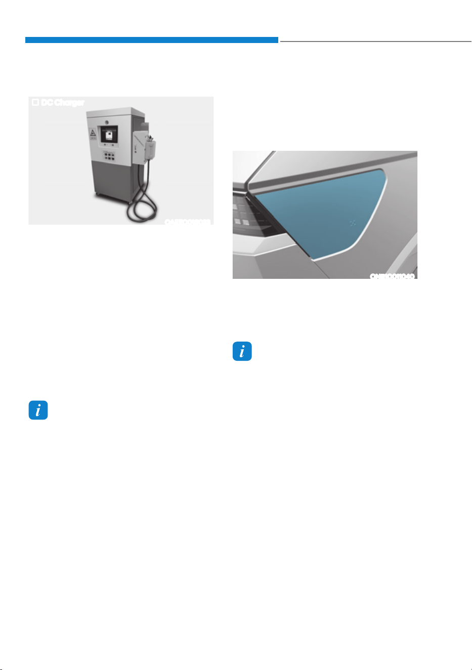
DC Charge
DC Charger
OAEEQ016023
You can charge at high speeds at public
charging stations. Refer to the respective
company’s manual that is provided for
each DC charger type.
Battery performance and durability can
deteriorate if the DC charger is used
constantly.
Use of DC charge should be minimized
in order to help prolong high voltage
battery life.
Actual charger image and charging
method may vary in accordance with
the charger manufacturer.
Information
If you use a DC charger when the vehicle
is already fully charged, some DC
chargers will send out an error message.
When the vehicle is fully charged, do not
charge the vehicle.
How to Connect DC Charger
1. Depress the brake pedal and apply the
parking brake.
2. Turn OFF all switches, shift to P (Park),
and turn OFF the vehicle.
ONE1Q011040
3. Open the charging door.
For more details, refer to ‘Electric
Charging Door’ in this chapter.
Information
If you cannot open the charging door due
to freezing weather, tap lightly or remove
any ice near the charging door. Do not try
to forcibly open the charging door.
4. Check whether there is dust or foreign
substances inside the charging
connector and charging inlet.
5. Hold the charging connector handle
and connect it to the vehicle charging
inlet. Push the connector all the way
in. If the charging connector and
charging terminal are not connected
properly, this may cause a fire.
Refer to the manual for each type of
DC charger for how to charge and
remove the charger.
01
1-35
ONE1Q011041
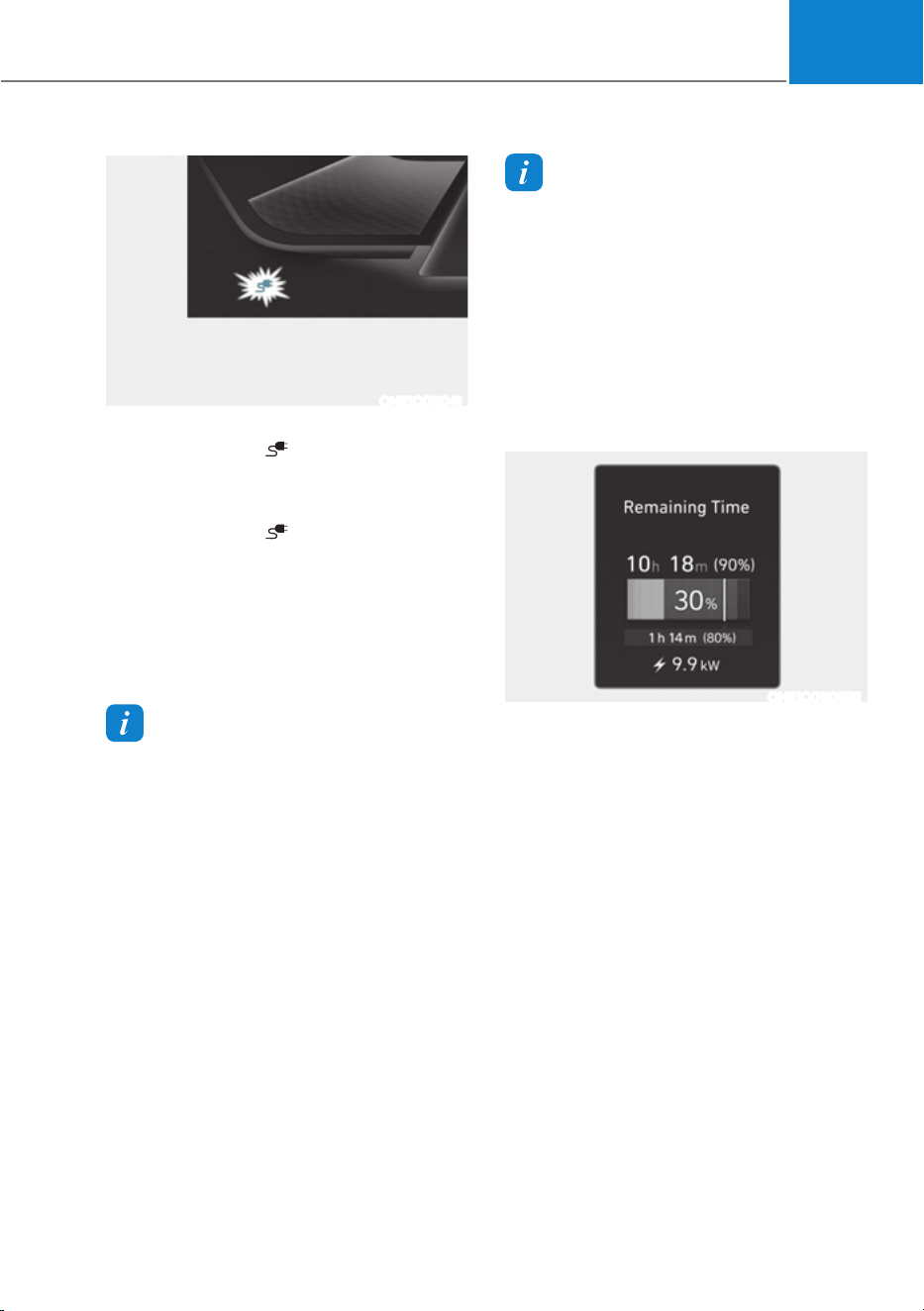
6. Check if the charging connector
indicator light (
) of the high voltage
battery in the instrument cluster is
turned ON. Charging connector is not
active when the charging connector
indicator light (
) is OFF.
When the charging connector is not
connected properly, reconnect the
charging cable to charge it again.
During cold weather, DC charging
may not be available to prevent high
voltage battery degradation.
Information
To control the temperature of the high
voltage battery while charging or when
the battery temperature is high, the air
conditioner is used to cool down the
battery. It may generate noise or vibration
from operation of the air conditioner
compressor and cooling fan, but it is a
normal condition when charging the high
voltage battery. Also, the air conditioner’s
performance may be degraded due to
operation of the cooling system to charge
the high voltage battery. This is a normal
condition.
Information
(YHQWKRXJKFKDUJLQJLVSRVVLEOHZLWK
the Start/Stop button in the ON/START
position, for you safety, start charging
when the Start/Stop button is in the
OFF position and the vehicle shifted to P
(Park). After charging has started, you
can use electrical components such as the
radio by pressing the Start/Stop button to
the ACC or ON position.
During charging, the gear cannot be
shifted from P (Park) to any other gear.
ONE1Q011059E
7. After charging has started, the
estimated charging time is displayed
on the instrument cluster for about 1
minute.
If you open the driver seat door while
charging, the estimated charging time
is also displayed on the instrument
cluster for about 1 minute.
Foreword / Starting your Electric vehicle
1-36
Information
ś Depending on the condition and
durability of the high voltage battery,
charger specifications, and ambient
temperature, the time required for
charging the battery may vary.
ś In rare cases, you might hear high
frequency noise (very little beep sound)
outside the car when charging with
400V fast charger that is deteriorated
or has long communication delay.
The high frequency noise can be
generated only when the car tries to
reduce its own electromagnetic waves
to keep fast charging as possible.
So there is no need to worry about this
little noise, because it is the intentional
operation of the car that does not
affect any charging performance or the
vehicle itself at all.
Checking Charging Status
When charging the high voltage battery,
the charge level can be checked from
outside the vehicle.
For more details, refer to ‘Charge
Indicator Lamp for Electric Vehicle’ in
this chapter.
How to Disconnect DC Charger
1. Remove the charging connector
when DC charging is completed, or
after you stop charging using the DC
charger. Refer to each respective DC
charger manual for details about how
to disconnect the charging connector.
2. Make sure to completely close the
charging door.
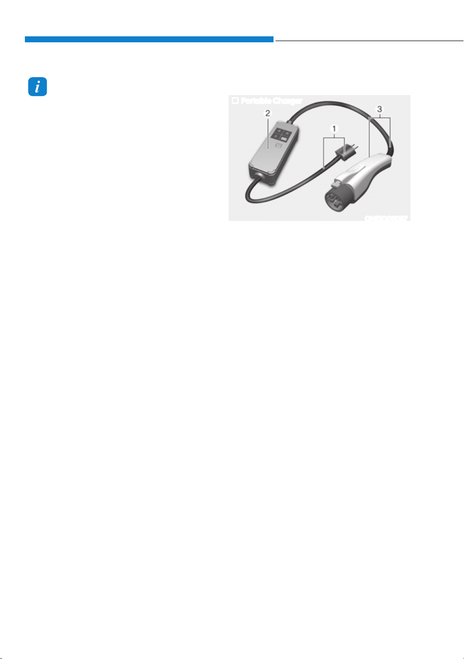
Portable Charge
Portable Charger
ONE1Q011087
(1) Code and Plug (Code set)
(2) Control Box
(3) Charging Cable and Charging
Connector
Portable Charge can be used when AC
Charge or DC Charge is not available by
using household electricity.
01
1-37
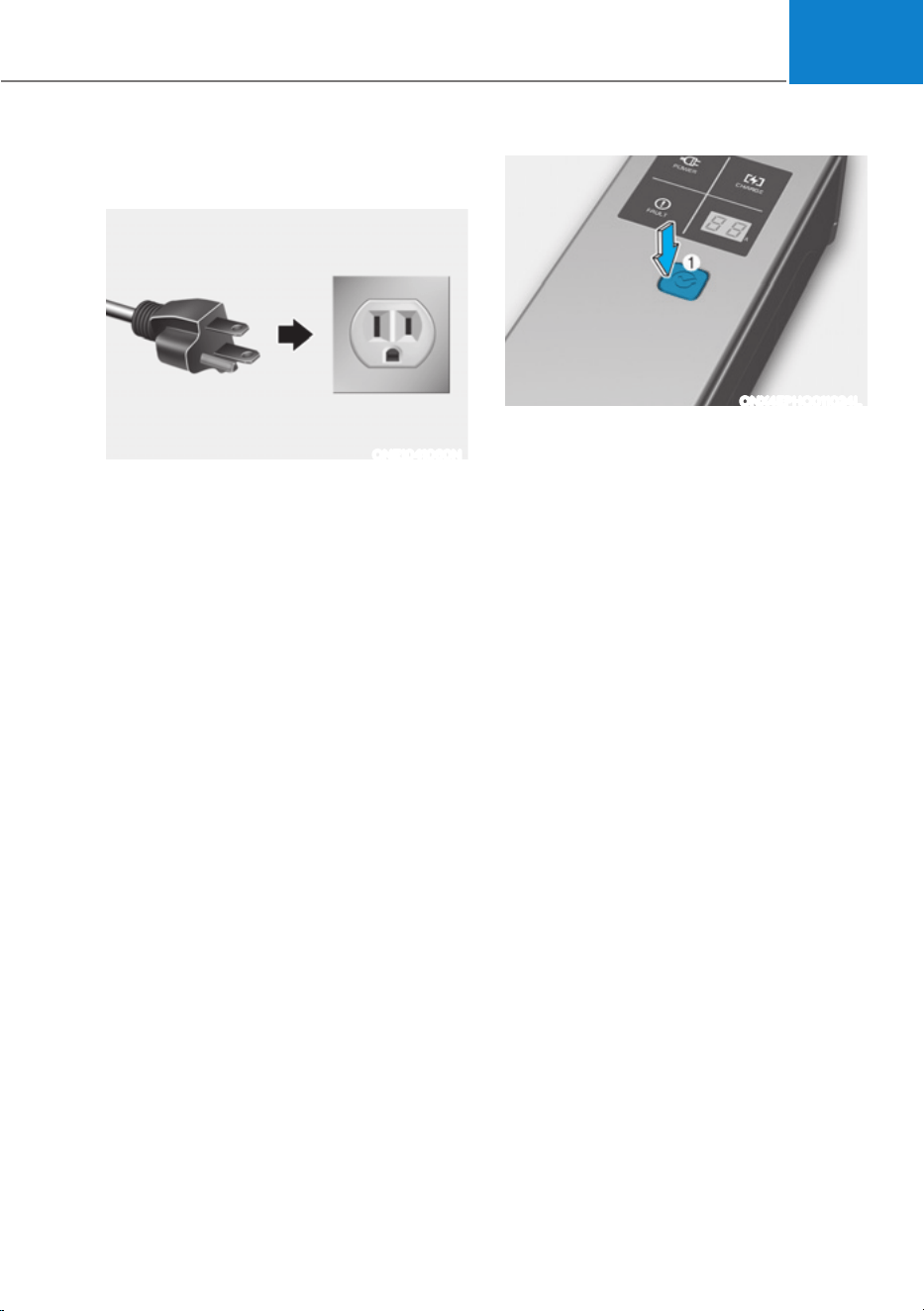
How to Set the Charge Level of the
Portable Charger
ONE1041060N
1. Check the rated current of the electric
outlet prior to connecting the plug to
the outlet.
2. Connect the plug to a household
electric outlet.
3. Check the display window on the
control box.
ONX4EPHQ011024L
4. Press the button (1) on the front of
the control box for 2 to 8 seconds
to adjust the charge level. (Refer to
charging cable type and example for
setting the charge level.)
5. The charge level on the display
window of the control box changes
every time you press the button (1).
6. When setting the charge level is
complete, start charging according to
the portable charge procedure.
Foreword / Starting your Electric vehicle
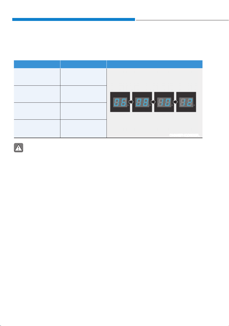
1-38
à Example for setting the ICCB charge level
The example is only for reference and may vary according to the surrounding
environment.
Outlet current ICCB charge level Control box display window
14-16A 12A
ONX4EPHQ011007L
13-12A 10A
11-10A 8A
9-8A 6A
CAUTION
Please make sure that charge level selection matches the capacity of your circuit
breaker to avoid blown fuse.
01
1-39
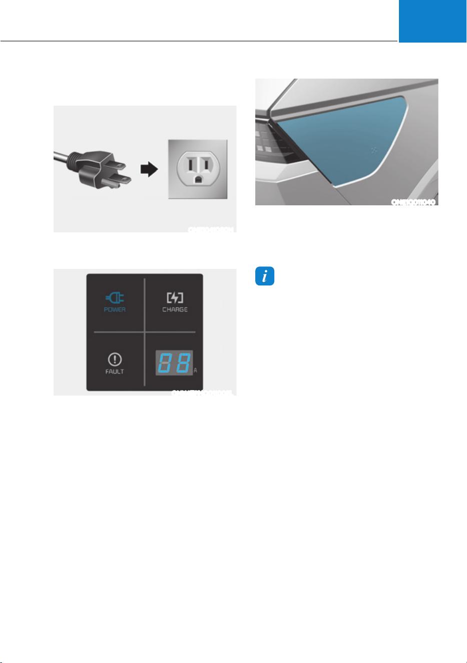
How to Connect Portable Charger
(ICCB: In-Cable Control Box)
ONE1041060N
1. Connect the plug to a household
electric outlet.
ONX4EPHQ011005L
2. Check if the power lamp (green)
illuminates on the control box.
3. Depress the brake pedal and apply the
parking brake.
4. Turn OFF all switches, shift to P (Park),
and turn OFF the vehicle.
If charging is initiated without the
gear in P (Park), the charging will start
after the gear is automatically shifted
to P (Park).
ONE1Q011040
5. Open the charging door.
For more details, refer to ‘Electric
charging door’ in this chapter.
Information
If you cannot open the charging door due
to freezing weather, tap lightly or remove
any ice near the charging door. Do not try
to forcibly open the charging door.
6. Open the protection caps of the
charging connector and the charging
plug. Check if there are any foreign
substances or dust.
7. Hold the charging connector handle
and connect it to the vehicle charging
inlet. Push the connector all the way
in. If the charging connector and
charging terminal are not connected
properly, this may cause a fire.
Foreword / Starting your Electric vehicle
1-40
Information
Locking Charging Cable
6HOHFWµ6HWWLQJVĺ(&29HKLFOHĺ
Charging Connector Locking Mode’ in
the infotainment. The charging connector
is locked in the inlet at a different period
according to which mode is selected.
ś Always mode : The connector locks
when the charging connector is plugged
into the charging inlet.
ś While charging mode : The connector
locks when charging starts.
For more details, refer to “Locking
Charging Cable” in this chapter.
ONX4EPHQ011006L
8. Charging starts automatically
(charging lamp illuminates).
ONE1Q011041
9. Check if the charging indicator light
(
) of the high voltage battery in
the instrument cluster is turned ON.
Charging is not active when the
charging indicator light (
) is OFF.
When the charging connector is not
connected properly, reconnect the
charging cable to charge it again.
01
1-41
Information
To control the temperature of the high
voltage battery while charging, the air
conditioner is used to cool down the
battery. It may generate noise or vibration
from operation of the air conditioner
compressor and cooling fan, but it is a
normal condition when charging the high
voltage battery. Also, the air conditioner’s
performance may be degraded due to
operation of the cooling system to charge
the high voltage battery. This is a normal
condition.
Information
(YHQWKRXJKFKDUJLQJLVSRVVLEOHZLWK
the Start/Stop button in the ON/START
position, for you safety, start charging
when the Start/Stop button is in the
OFF position and the vehicle shifted to P
(Park). After charging has started, you
can use electrical components such as the
radio by pressing the Start/Stop button to
the START or ON position.
During charging, the gear cannot be
shifted from P (Park) to any other gear.
ONE1Q011058E
10. After charging has started, the
estimated charging time is displayed
on the instrument cluster for about 1
minute.
If you open the driver seat door while
charging, the estimated charging time
is also displayed on the instrument
cluster for about 1 minute. When
scheduled charging or scheduled
air conditioner/heater is set, the
estimated charging time is displayed
as “--” .
Information
Depending on the condition and durability
of the high voltage battery, charger
specifications, and ambient temperature,
the time required for charging the battery
may vary.
Checking Charging Status
When charging the high voltage battery,
the charge level can be checked from
outside the vehicle.
For more details, refer to ‘Charge
Indicator Lamp for Electric Vehicle’ in
this chapter.
Foreword / Starting your Electric vehicle
1-42
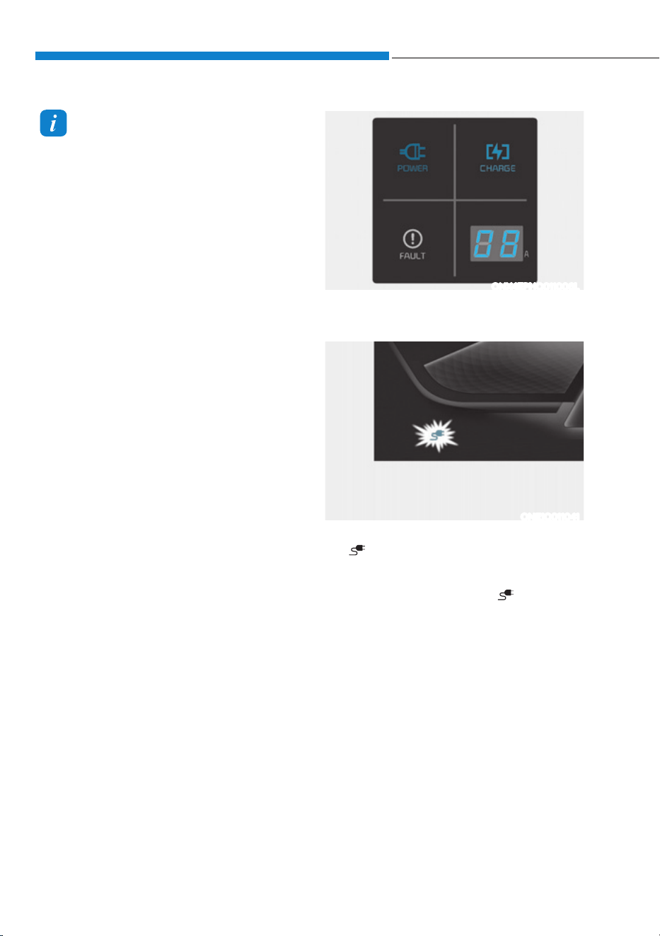
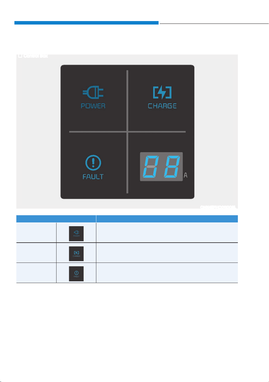
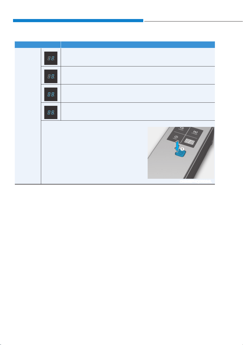
Charging Status Indicator Lamp for Portable Charger
Control Box
ONX4EPHQ011008L
Indicator Details
POWER On : Power on
CHARGE
On : Charge
Blink : Current limit due to high plug temperature or high
internal temperature
FAULT
Blink : Charging interrupted
01
1-43
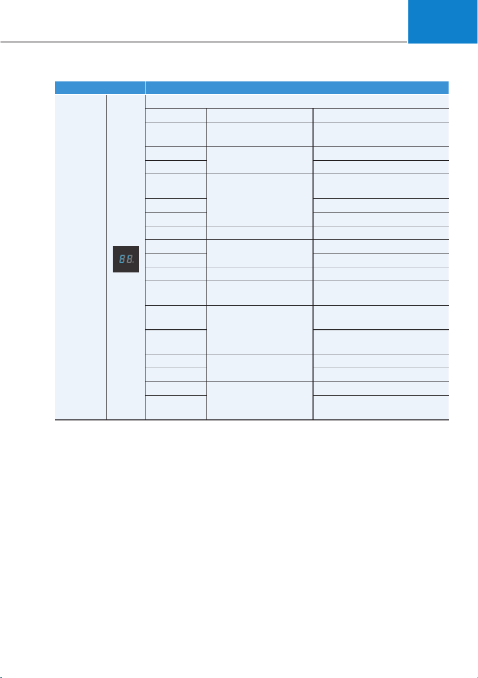
Indicator Details
Error code
On : Error while charging/ Error during self-diagnosis
Error code Item Cause
E1
Control Pilot
communication
Vehicle communication error
E2
Leakage
Current leakage
E3 Charger error
E4
Plug temperature
Plug overtemperature
warning
E5 Plug temperature failure
E6 Charger error
E7 Overcurrent Charging overcurrent warning
E8
Internal temperature
Charger overheating
E9 Charger error
F1 Relay fusion Charger error
F2
Ground Monitoring/
Interrupt
Poor grounding of outlet
F3
Switched mode power
supply power failure
Switched mode power supply
error (voltage failure)
F4
Switched mode power supply
error (abnormal voltage)
F5
Control Pilot voltage
error
Control Pilot (-) voltage error
F6 Control Pilot (+) voltage error
F7
Temperature sensor
error
Plug temperature sensor error
F8
PCB internal temperature
sensor error
Foreword / Starting your Electric vehicle
1-44
Indicator Details
CHARGE
LEVEL
12 A
10 A
8 A
6 A
The charging current changes whenever the
button (1) is pressed for less than 1 sec with the
charger plugged into an electrical outlet but
not the vehicle.
* The control box
ONX4EPHQ011024L
01
1-45
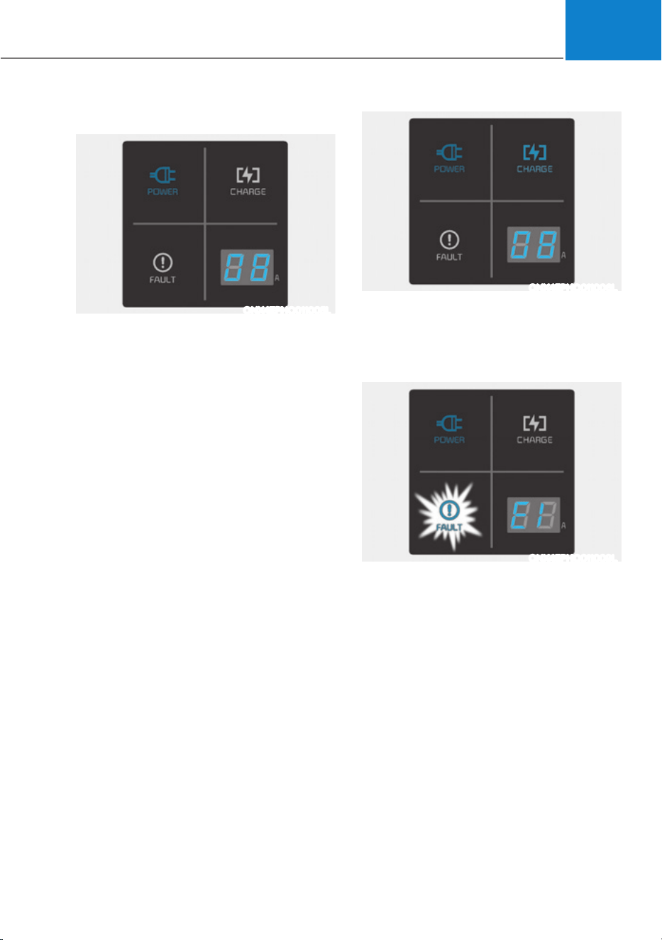
Status / Diagnosis / Countermeasure
ONX4EPHQ011005L
ś Charging connector plugged into
vehicle (POWER Green ON)
ś Plug connected to an electric outlet
(POWER Green ON)
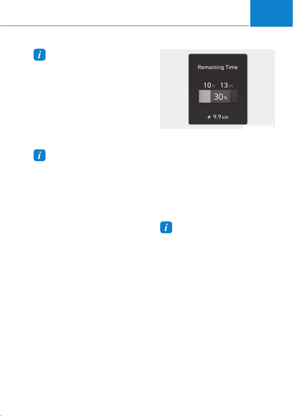
ONX4EPHQ011006L
While charging
ś Charge indicator (POWER Green ON /
CHARGE Blue ON)
ś Charging current
ONX4EPHQ011009L
Before plugging charging connector into
vehicle (POWER Green ON, FAULT Red
blink)
ś Abnormal temperature
ś ICCB (In-Cable Control Box) failure
Contact an authorized HYUNDAI dealer.
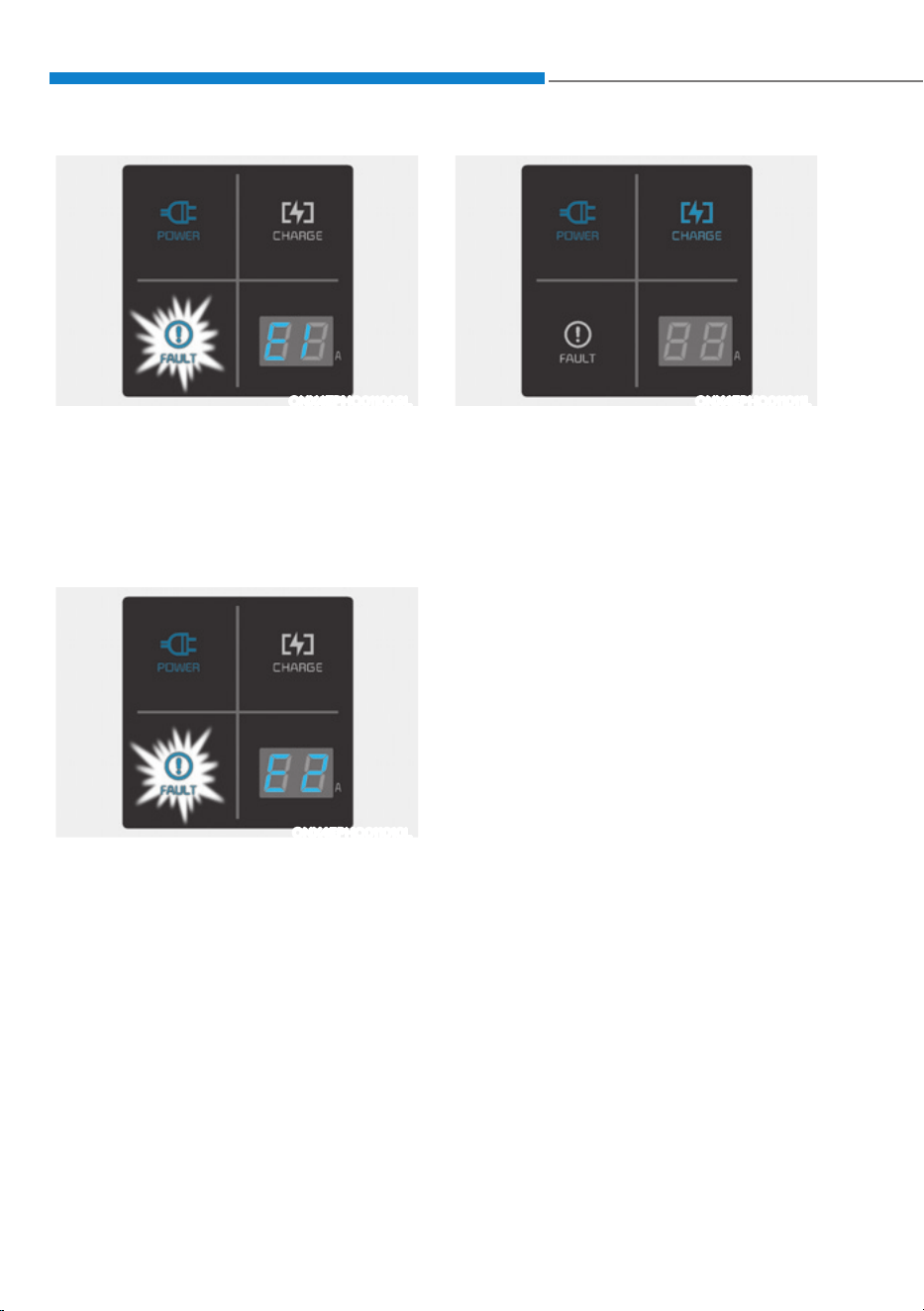
Foreword / Starting your Electric vehicle
1-46
ONX4EPHQ011009L
Plugged into vehicle (POWER Green ON,
FAULT Red Blink)
ś Diagnostic device failure
ś Current leakage
ś Abnormal temperature
Contact an authorized HYUNDAI dealer.
ONX4EPHQ011010L
ś Leakage current failure (POWER Green
ON, FAULT Red Blink)
ś After disconnecting and reconnecting
the power plug, press and release the
button for 2 seconds or longer to clear
the error.
Contact an authorized HYUNDAI dealer.
ONX4EPHQ011011L
Power saving mode
ś 7-segment display is turned off if there
is no status change for more than 1
minute.
01
1-47
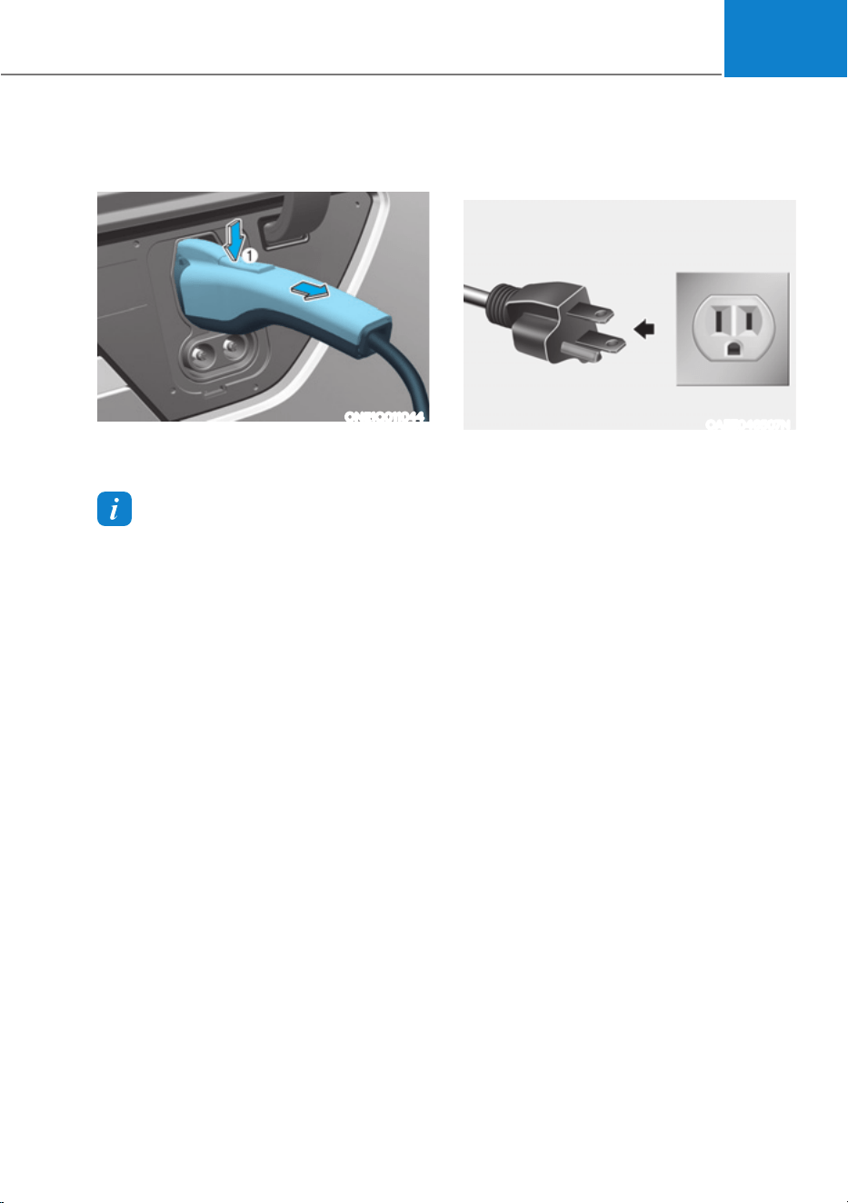
How to Disconnect Portable Charger
(ICCB: In-Cable Control Box)
ONE1Q011044
1. Hold the charging connector handle
and pull it out.
Information
To prevent charging cable theft,
the charging connector cannot be
disconnected from the inlet when the
doors are locked or the charging connector
is in the LOCK mode. Unlock all doors to
disconnect the charging connector from
the inlet.
However, if the vehicle is in the charging
connector AUTO mode, the charging
connector automatically unlocks from the
inlet when charging is completed.
If the charging connector is disconnected
while the release button is not pressed, the
connector and the inlet may be damaged.
For more details, refer to “Charging
Connector AUTO/ LOCK Mode” in this
chapter.
If the release button does not work even
after the all doors are unlocked, pull
the emergency lift cable in the motor
room and press the release button in the
connector to disconnect it from the vehicle.
If the release button still does not work,
consult an authorized HYUNDAI dealer.
2. Make sure to completely close the
charging door.
OAEE046507N
3. Disconnect the plug from the
household electric outlet. Do not pull
the cable when disconnecting the
plug.
4. Close the protection caps of the
charging connector and the charging
plug to protect them from foreign
substances.
5. If the personal charging connector is
used, store the connector in the cable
compartment.

Foreword / Starting your Electric vehicle
1-48
Precautions for Portable Charger
(ICCB: In-Cable Control Box)
śUse the portable charger that is certified
by HYUNDAI Motors.
śDo not try to repair, disassemble, or adjust
the portable charger.
śDo not use an extension cord or adapter.
śStop using immediately when failure
occurs.
śDo not touch the plug and charging
connector with wet hands.
śDo not touch the terminal part of the AC
charging connector and the AC charging
inlet on the vehicle.
śDo not connect the charging connector
to voltage that does not comply with
regulations.
śDo not use the portable charger if it is
worn out, exposed, or there exists any
type of damage on the portable charger.
śIf the ICCB case and AC charging
connector is damaged, cracked, or the
wires are exposed in any way, do not use
the portable charger.
śDo not let children operate or touch the
portable charger.
śKeep the control box free of water.
śKeep the normal charging connector or
plug terminal free of foreign substances.
śDo not step on the cable or cord. Do not
pull the cable or cord and do not twist or
bend it.
śDo not charge when there is lightning.
śDo not drop the control box or place a
heavy object on the control box.
śDo not place an object that can generate
high temperatures near the charger when
charging.
śCharging with the worn out or damaged
household electric outlet can result in a
risk of electric shock. If you are in doubt
to the household electric outlet condition,
have it checked by a licensed electrician.
śStop using the portable charger
immediately if the household electric
outlet or any components is overheated
or you notice burnt odors.

01
1-49
&+$5*,1*7+((/(&75,&9(+,&/(ǣ$%58376723Ǥ
Action to be taken when charging stops abruptly
When the high voltage battery does not charge, check the followings:
1. Check the charging setting for the vehicle. Refer to “Charge Management”, in this
chapter (for example, When scheduled charging is set, charging is not initiated
immediately when the AC charger or portable charger (ICCB: In-Cable Control Box)
is connected.)
2. Check the operation status of AC charger, portable charger and DC charger.
(Charging Status Indicator Lamp for Portable Charger, refer to “Checking Charging
Status” for trickle charge in this chapter.)
à Actual method for indicating the charging status may vary in accordance with the
charger manufacturer.
3. When the vehicle does not charge and a warning message appears on the cluster,
check the corresponding message. Refer to “LCD Display Messages”, in this chapter.
4. If the vehicle is properly charged when charged with another normally working
charger, contact the charger manufacturer.
5. If the vehicle does not charge when charged with another normally working
charger, contact an authorized HYUNDAI dealer for inspection.
6. If charging fails and the service warning light (
) is lit in the cluster, contact an
authorized HYUNDAI dealer.
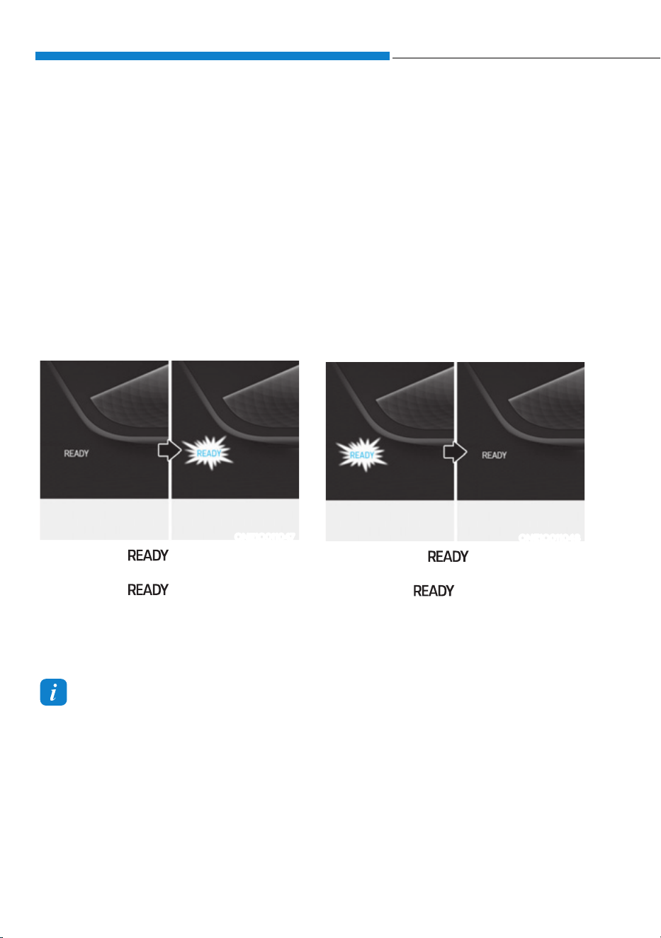
Foreword / Starting your Electric vehicle
1-50
DRIVING ELECTRIC VEHICLE
How to Start the Vehicle
1. Holding the smart key, sit in the
driver’s seat.
2. Fasten the seat belt before starting
the vehicle.
3. Make sure to engage the parking
brake.
4. Turn OFF all electrical devices.
5. Make sure to depress and hold the
brake pedal.
6. While depressing the brake pedal,
shift to P (Park).
7. Depress and hold the brake pedal
while pressing the Start/Stop button.
ONE1Q011047
8. When the “ ” indicator is ON,
you can drive the vehicle.
When the “
” indicator is OFF,
you cannot drive the vehicle. Start the
vehicle again.
9. Depress and hold the brake pedal and
shift to the desired position.
Information
While the charging cable is connected, the
gear cannot be shift from P (Park) to any
other gear for safety reasons.
10. Release the parking brake and slowly
release the brake pedal. Check if the
vehicle slowly moves forward, then
depress the accelerator pedal.
How to Stop the Vehicle
1. Hold down the brake pedal while the
vehicle is parked.
2. While depressing the brake pedal,
shift to P (Park).
3. While depressing the brake pedal,
engage the parking brake.
4. While depressing the brake pedal,
press the Start/Stop button and turn
off the vehicle.
ONE1Q011048
5. Check if the “ ” indicator is
turned OFF on the instrument cluster.
When the “
” indicator is ON
and the gear is in a position other than
P (Park), the driver can accidently
depress the accelerator pedal, causing
the vehicle to move unexpectedly.
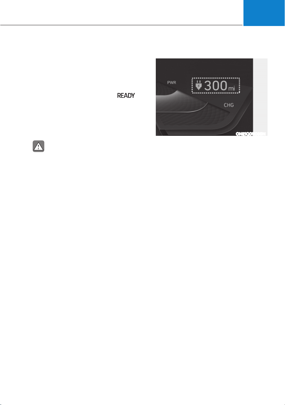
01
1-51
Virtual Engine Sound System
The Virtual Engine Sound System
generates engine sound for pedestrians
to hear vehicle sound because there is
no sound while the Electric Vehicle (EV)
is operating.
ś If the vehicle is in the ready (
)
mode and the gear is not in P (Park),
the VESS will be operated.
ś When the gear is shifted to R
(Reverse), an additional warning
sound will be heard.
CAUTION
ś The vehicle is much quieter while
driving than a conventional gasoline-
powered vehicle. Be aware of your
surroundings and always drive safely.
ś After you park the vehicle or while
you are waiting at a traffic light,
check whether there are children or
obstacles around the vehicle.
ś Check if there is something behind
the vehicle when driving in reverse.
Pedestrians may not hear the sound
of the vehicle.
Distance to Empty
ONE1Q011099N
The distance to empty is displayed
differently according to the selected
drive mode in the Drive Mode Integrated
Control System.
For more information, refer to “Drive
Mode Integrated Control System” in
chapter 6.
When destination is not set
ś On average, a vehicle can drive about
200 miles (320 km) (Standard type) /
300 miles (400 km) (Extended type).
ś Under certain circumstances where
the air conditioner/heater is ON,
the distance to empty is impacted,
resulting in a possible distance range
from 106 ~ 286 miles (170 ~ 460 km)
(Standard type) / 130 ~ 300 miles
(210 ~ 570 km) (Extended type).
When using the heater during cold
weather or driving at high speed, the
high voltage battery consumes a lot
more electricity. This may reduce the
distance to empty significantly.
ś After ‘0 km’ has been displayed,
the vehicle can drive an additional
2~5 miles (3~8 km) depending on
driving speed, heater/air conditioner,
weather, driving style, and other
factors.

Foreword / Starting your Electric vehicle
1-52
ś Distance to empty that is displayed
on the instrument cluster after
completing a recharge may vary
significantly depending on previous
operating patterns.
When previous driving patterns
include high speed driving, resulting
in the high voltage battery using more
electricity than usual, the estimated
distance to empty is reduced. When
the high voltage battery uses little
electricity in ECO mode, the estimated
distance to empty increases.
ś Distance to empty may depend on
many factors such as the charge
amount of the high voltage battery,
weather, temperature, durability of
the battery, geographical features,
and driving style. When the ambient
temperature is low such as in winter,
the actual driving distance may
reduce due to degradation of the
battery.
ś Natural degradation may occur with
the high voltage battery depending
on the number of years the vehicle is
used. This may reduce the distance to
empty.
When destination is set
When the destination is set, the distance
to empty may change. The distance
to empty is recalculated using the
information of the destination. However,
the distance to empty may vary
significantly based on traffic conditions,
driving habits, and condition of the
vehicle.
Tips for Improving Distance to
Empty
ś If you operate the air conditioner /
heater too much, the driving battery
uses too much electricity. This
may reduce the distance to empty.
Therefore, it is recommended that
you set the cabin temperature to
22°C AUTO. This setting that has
been certified by various assessment
tests to maintain optimal energy
consumption rates while keeping the
temperature fresh.
Turn OFF the heater and air
conditioner if you do not need them.
ś When the heater or air conditioning
system is on the energy consumption
is reduced if recirculation mode is
selected instead of selecting the fresh
mode. The fresh mode requires large
amount of energy consumption as
the outside air has to be re-heated or
cooled.
ś When using the heater or air
conditioning system use the DRIVER
ONLY or scheduled air conditioner/
heater function.
ś Depress and hold the accelerator
pedal to maintain speed and drive
economically.
ś Gradually depress and release the
accelerator pedal when accelerating
or decelerating.
ś Always maintain specified tire
pressures.
ś Do not use unnecessary electrical
components while driving.
ś Do not load unnecessary items in the
vehicle.
ś Do not mount parts that may increase
air resistance.
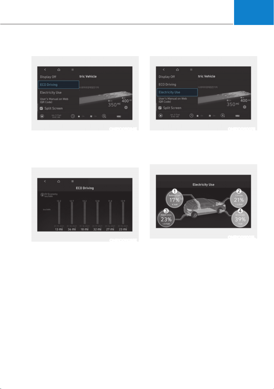
01
1-53
ECO Driving
ONE1Q011034E
In order to check the ECO driving history,
VHOHFWœ0HQXƟ(&2'ULYLQJŔRQWKH
screen.
Electric energy economy history
ONE1Q011035E
It is possible to check the history of
electric energy economy with the date
and distance of previous driving. The
icon is displayed on the most efficient
electric energy economy record.
Electricity Use
ONE1Q011007E
In order to check the current energy
consumption for each system of the
YHKLFOHVHOHFWœ0HQXƟ(OHFWULFLW\8VHŔRQ
the screen.
ONE1Q011002L
1. ‘Battery care’ shows the momentary
power and energy consumption which
are used when:
- Operating the winter mode to
increase the battery temperature
during winter to improve the driving
performance.
- Cooling down the battery
temperature during summer to
prevent over temperature of the
battery.
2. ‘Climate’ shows the power and energy
consumption which are used by the
heater or air conditioner.
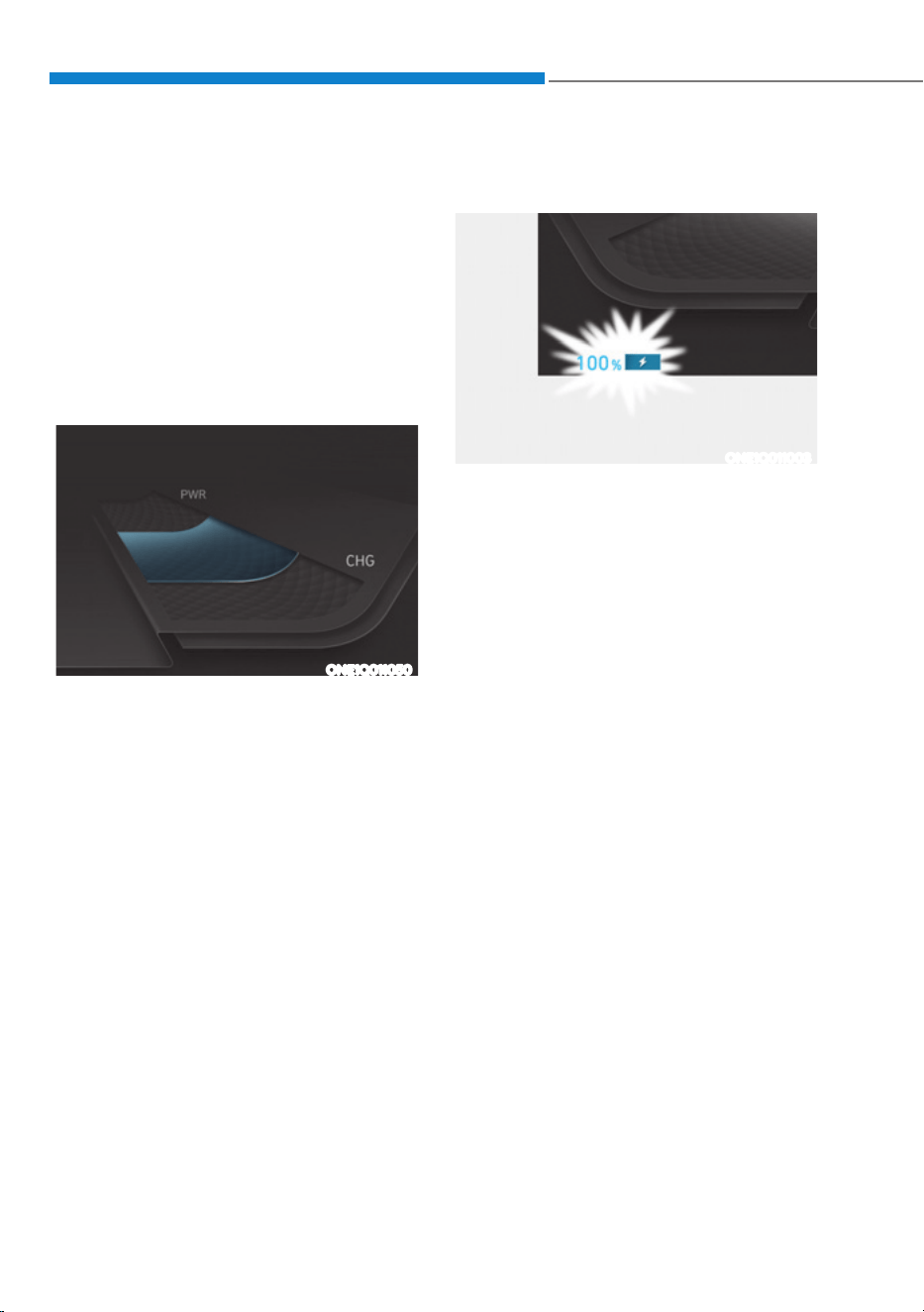
Foreword / Starting your Electric vehicle
1-54
3. ‘Electronics’ shows the power and
energy consumption which are used
by the vehicle systems including the
cluster, infotainment system(speaker
and navigation), headlamp, vehicle
control unit, etc.
4.
‘Driving’ shows the total power
and energy consumption of the
driving motor’s driving energy and
regenerative energy.
Power/Charge Gauge
ONE1Q011050
The Power/Charge Gauge shows the
energy consumption rate of the vehicle
and the charge/discharge status of the
regenerative brakes.
ś POWER :
It shows the energy consumption rate
of the vehicle when driving uphill or
accelerating. The more electric energy
is used, the higher the gauge level.
ś CHARGE :
It shows the charging status of the
battery when it is being charged by
the regenerative brakes (decelerating
or driving on a downhill road). The
more electric energy is charged, the
lower the gauge level.
State Of Charge (SOC) Gauge for
High Voltage Battery
ONE1Q011003
ś The SOC gauge shows the charging
status of the high voltage battery.
ś The low percentage number on the
indicator indicates that there is not
enough energy in the high voltage
battery. 100 % indicates that the
driving battery is fully charged.
ś When driving on highways or
motorways, make sure to check
in advance if the driving battery is
charged enough.

01
1-55
ONE1Q011011
When the remaining battery is lower than
10 % on the SOC gauge, the warning light
(
) turns ON to alert you of the battery
level.
When the warning light ( ) turns ON,
the vehicle can drive an additional 18 ~
25 miles (30 ~ 40 km) depending on the
driving speed, heater/air conditioner,
weather, driving style, and other factors.
Charging is required.
NOTICE
When the high voltage battery level is
low, the power down indicator light (
)
illuminates and the vehicle power is
limited.
Charge the battery immediately since
your vehicle may not be driven, or may
roll back on a slope with the indicator
light ON.
Aux. Battery Saver+
The Aux. Battery Saver+ is a function that
monitors the charging status of the 12 V
auxiliary battery.
If the auxiliary battery level is low, the
main high voltage battery charges the
auxiliary battery.
Information
ś The Aux. Battery Saver+ activates
maximum of 20 minutes. If the Aux.
Battery Saver+ function activates
more than 10 times consecutively, in
the Automatic Mode the function will
stop activating, judging that there is
a problem with the auxiliary battery.
In this case, drive the vehicle for some
period of time. The function will start
activating if the auxiliary battery
returns to normal.
ś The Aux. Battery Saver+ function
cannot prevent battery discharge if the
auxiliary battery is damaged, worn out,
used as a power supply or unauthorized
electronic devices are used.
ś If the Aux. Battery Saver+ function was
activated the high voltage battery level
may have decreased.
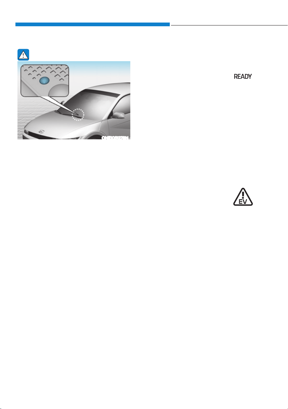
Foreword / Starting your Electric vehicle
1-56
WARNING
ONE1051278N
When the function is activating the
indicator lamp will illuminate and high
voltage electricity will be flowing in the
vehicle. Do not touch the high voltage
electric wire (orange), connector, and
all electric components and devices.
This may cause electric shock and lead
to injuries. Also, do not modify your
vehicle in any way. This may affect your
vehicle performance and lead to an
accident.
Warning and Indicator Lights
(related to electric vehicle)
Ready indicator
This indicator illuminates:
When the vehicle is ready to be driven.
- ON : Normal driving is possible.
- OFF : Normal driving is not possible,
or a problem has occurred.
- Blinking : Emergency driving.
When the ready indicator goes OFF
or blinks, there is a problem with the
system. In this case, have your vehicle
inspected by an authorized HYUNDAI
dealer.
Service Warning Light
This warning light illuminates:
ś When the Start/Stop button is in the
ON position.
- It illuminates for approximately 3
seconds and then goes off.
ś When there is a problem with related
parts of the electric vehicle control
system, such as sensors, etc.
When the warning light illuminates while
driving, or does not go OFF after starting
the vehicle, have your vehicle inspected
by an authorized HYUNDAI dealer.
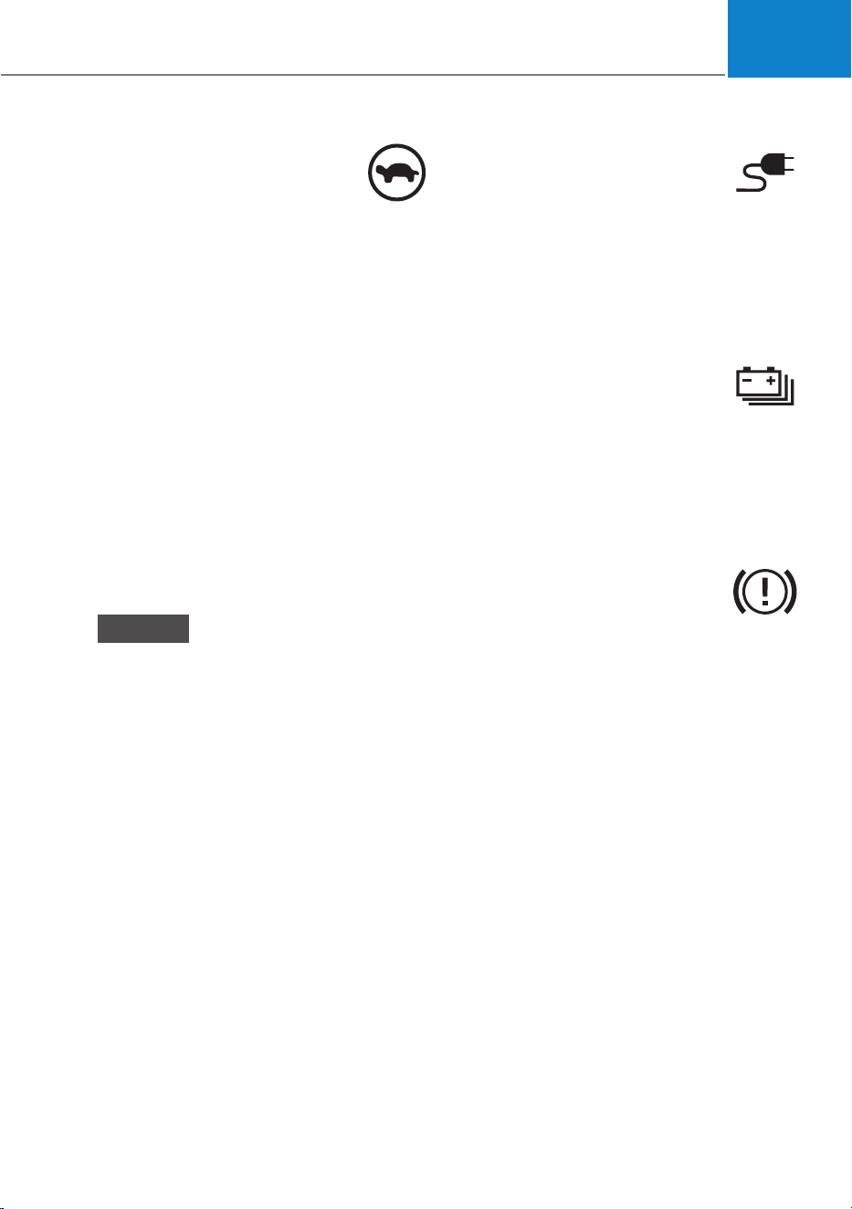
01
1-57
Power Down Indicator Light
This warning light illuminates:
ś When the Start/Stop button is in the
ON position.
- It illuminates for approximately 3
seconds and then goes off.
ś When the power is limited for the
safety of the high-powered parts of an
electric vehicle. The power is limited
for the following reasons.(Unless both
Service Warning Light and Power
Down Indicator Light illuminate at the
same time, it is not a failure.)
- The high voltage battery level is too
low or voltage is decreasing
- The temperature of the high voltage
battery is too high or too low
- The temperature of the motor is
high
NOTICE
ś Do not accelerate or start the vehicle
suddenly when the power down
indicator light is ON.
ś When the power is limited for the
safety of the high-powered parts of
an electric vehicle, the power down
indicator light illuminates. Your
vehicle may not be driven, or may roll
back on a slope with the indicator
light ON due to the limitation of
vehicle power.
Charging connector
Indicator Light
This warning light indicates the
connection status of the charging
connector. When the charging connector
is connected to the vehicle, the green
light illuminates for approximately 1
minute.
High Voltage Battery Level
Warning Light
This warning light illuminates:
ś When the high voltage battery level
is low.
ś When the warning light turns ON,
charge the battery immediately.
Regenerative Brake Warning
Light
This warning light illuminates:
When the regenerative brake does not
operate and the brake does not perform
well. This causes the Brake Warning
light (red) and Regenerative Brake
Warning Light (yellow) to illuminate
simultaneously.
In this case, drive safely and have your
vehicle inspected by an authorized
HYUNDAI dealer.
The operation of the brake pedal may
be more difficult than normal and the
braking distance can increase.
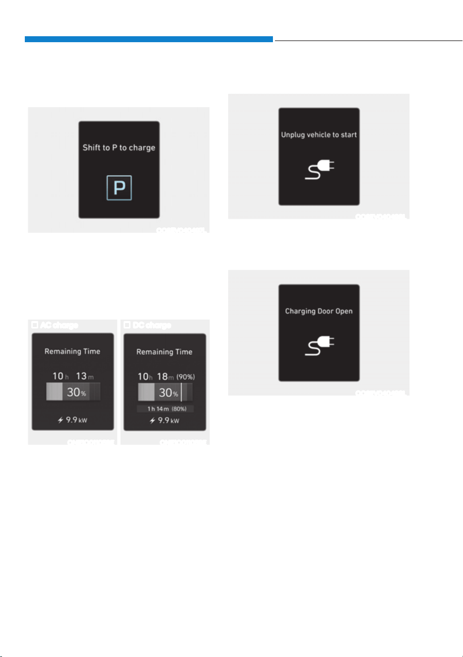
Foreword / Starting your Electric vehicle
1-58
LCD Display Messages
Shift to P to charge
OOSEV040497L
This message is displayed if you connect
the charging cable without the gear in
the P (Park) position.
Shift to P (Park) before connecting the
charging cable.
Remaining time
AC charge DC charge
ONE1Q011058E ONE1Q011059E
This message is displayed to notify the
remaining time to charge the battery to
the selected target battery charge level.
Unplug vehicle to start
OOSEV040498L
This message is displayed when you
start the vehicle without unplugging the
charging cable. Unplug the charging
cable, and then turn on the vehicle.
OOSEV040499L
This message is displayed when the
vehicle is driven with the charging door
opened. Close the charging door and
then start driving.
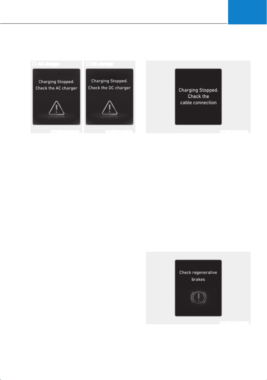
01
1-59
Charging Stopped. Check the AC/DC
charger
AC charge DC charge
OOSEV040500L OOSEV040501L
ś This warning message is displayed
when charging is stopped for the
reasons below:
- There is a problem with the external
AC charger or DC charger
- The external AC charger stopped
charging
- The charging cable is damaged
In this case, check whether there is any
problem with the external AC or DC
charger and charging cable.
If the same problem occurs when
charging the vehicle with a normally
operating AC charger or genuine
HYUNDAI portable charger, have your
vehicle inspected by an authorized
HYUNDAI dealer.
Charging Stopped. Check the cable
connection
OOSEV040502L
This warning message is displayed
when charging is stopped because the
charging connector is not correctly
connected to the charging inlet
In this case, separate the charging
connector and re-connect it and check
whether there is any problem (external
damage, foreign substances, etc.) with
the charging connector and charging
inlet.
If the same problem occurs when
charging the vehicle with a replaced
charging cable or genuine HYUNDAI
portable charger, have your vehicle
inspected by an authorized HYUNDAI
dealer.
Check regenerative brakes
OOSEV040503E
This warning message is displayed when
the regenerative brake system does not
work properly.
In this case, have the vehicle inspected
by an authorized HYUNDAI dealer.
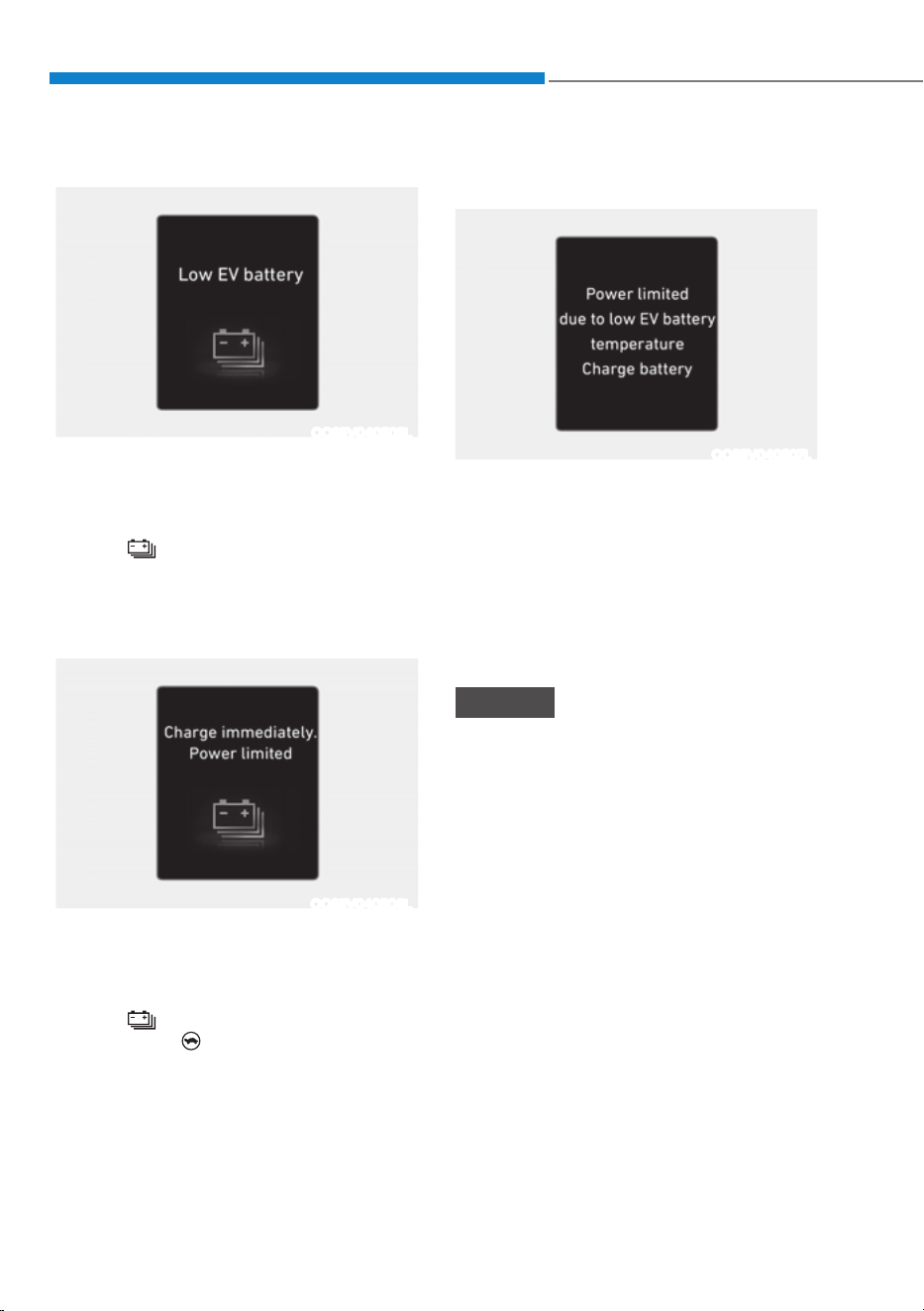
Foreword / Starting your Electric vehicle
1-60
Low EV battery
OOSEV040505L
When the high voltage battery level
reaches below approximately 10%, this
warning message is displayed.
The warning light on the instrument
cluster (
) will turn ON simultaneously.
Charge the high voltage battery
immediately.
Charge immediately. Power limited
OOSEV040506L
When the high voltage battery level
reaches below approximately 0%, this
warning message is displayed.
The warning light on the instrument
cluster (
) and the power down
warning light (
) will turn on
simultaneously.
The vehicle’s power will be reduced to
minimize the energy consumption of the
high voltage battery. Charge the battery
immediately.
Power limited due to low EV batter
temperature. Charge battery
OOSEV040507L
Both warning messages are displayed
to protect electric vehicle system when
outside temperature is low. If the high
voltage battery charging level is low
and parked outside in low temperature
for a long time, vehicle power could be
limited.
Charging the battery before driving helps
increase power.
NOTICE
If these warning messages are still
displayed even after the ambient
temperature has increased, have the
vehicle inspected by an authorized
HYUNDAI dealer.

01
1-61
EV Battery Overheated! Stop vehicle
OOSEV040509L
This warning message is displayed to
protect battery and electric vehicle
system when the high voltage battery
temperature is too high.
Turn off the Start/Stop button and
stop the vehicle so that the battery
temperature decreases.
Power limited
ONE1Q011008L
This warning message is displayed:
ś When the START/STOP button is in
the ON position.
- It illuminates for approximately 3
seconds and then goes off.
ś When the power is limited for the
safety of the high-powered parts of an
electric vehicle. The power is limited
for the following reasons. (Unless
both Service Warning Light and Power
Down Indicator Light illuminate at the
same time, it is not a failure.)
- The high voltage battery level is too
low or voltage is decreasing
- The temperature of the high voltage
battery is too high or too low
- The temperature of the motor is
high
NOTICE
ś When this warning message is
displayed, do not accelerate or start
the vehicle suddenly.
ś When the power is limited for the
safety of the high-powered parts
of an electric vehicle, the warning
message is displayed. Your vehicle
may not be driven, or may roll back
on a slope with the warning message
displayed due to the limitation of
vehicle power.
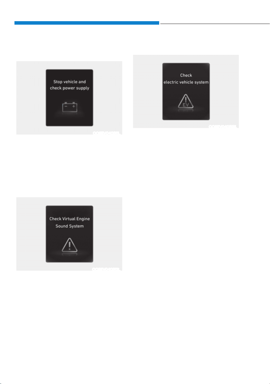
Foreword / Starting your Electric vehicle
1-62
Stop vehicle and check power
supply
OOSEV040511L
This warning message is displayed when
a failure occurs in the power supply
system.
In this case, park the vehicle in a safe
location and tow your vehicle to the
nearest authorized HYUNDAI dealer and
have the vehicle inspected.
Check virtual engine sound system
OOSEV040512L
This message is displayed when there is
a problem with the Virtual Engine Sound
System (VESS).
In this case, have the vehicle inspected
by an authorized HYUNDAI dealer.
Check electric vehicle system
OOSEV040513L
This warning message is displayed when
there is a problem with the electric
vehicle control system.
Refrain from driving when the warning
message is displayed.
In this case, have the vehicle inspected
by an authorized HYUNDAI dealer.

01
1-63
If an Accident Occurs
WARNING
ś When a vehicle accident occurs,
move the vehicle to a safe place,
turn OFF the vehicle and disconnect
the high voltage cut-off switch from
the auxiliary battery (12V) to prevent
high voltage electricity from flowing.
ś If electric wires are exposed from
inside or outside the vehicle, do not
touch the wires.
Also, do not touch the high voltage
electric wire (orange), connector,
and all electric components and
devices. This may cause electric
shock and lead to injuries.
WARNING
ś When a vehicle accident occurs and
the high voltage battery is damaged,
harmful gas and electrolytes may
leak. Be careful not to touch the
leaked liquid.
ś When you suspect leakage of
inflammable gas and other harmful
gases, open the windows and
evacuate to a safe place. If any
leaked fluid comes in contact with
your eyes or skin, immediately clean
the affected area thoroughly with
tap water or saline solution and
have doctors inspect it as soon as
possible.
WARNING
ś If a small scale fire occurs, use a fire
extinguisher (ABC, BC) that is meant
for electrical fires. If it is impossible
to extinguish the fire in the early
stage, maintain a safe distance from
the vehicle and immediately call your
local fire emergency responders.
Also, advise them that an electric
vehicle is involved.
ś If the fire spreads to the high
voltage battery, large amount of
water is needed to put out the fire.
Using small amount of water or
fire extinguishers not meant for
electrical fires could cause serious
injury or death from electrical
shocks.
WARNING
ś If you cannot put out the fire
immediately, the high voltage
battery may explode. Evacuate to
a safe place and do not let other
people approach the site.
Contact the fire department and
notify them of an electric vehicle fire.
ś If the vehicle is flooded with water,
immediately turn off the vehicle and
evacuate to a safe place. Contact
the fire department or an authorized
HYUNDAI dealer.
SAFETY PRECAUTIONS FOR ELECTRIC VEHICLE
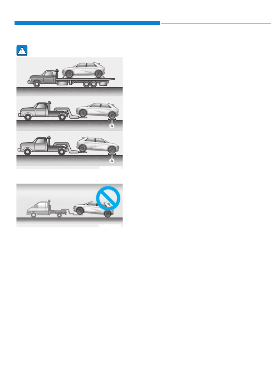
Foreword / Starting your Electric vehicle
1-64
WARNING
ONE1081011
[A] : Dollies
ONE1081015
ś If towing is required, lift all four
wheels off the ground and tow the
vehicle. If you must tow the vehicle
using only two wheels, lift the front
wheels off the ground and tow the
vehicle.
ś If you tow the vehicle while the
rear wheels are touching the
ground, the vehicle motor may
generate electricity and the motor
components may be damaged or a
fire may occur.
ś When a vehicle fire occurs due to the
battery, there is a risk of a second
fire. Contact the fire department
when towing the vehicle.
Other Precautions for Electric
Vehicle
ś When you paint or apply heat
treatment to the vehicle as a result of
an accident, the performance of the
high voltage battery can be reduced.
ś If heat treatment is required, contact
an authorized HYUNDAI dealer.
ś When you clean the motor
compartment, do not use high
pressure water to wash. This may
cause an electric shock due to a
discharge in high voltage electricity,
or damage the vehicle’s electric
system.
ś Use, remodel, or install genuine
Hyundai part or the equivalent (of
the genuine part) specified for your
vehicle.
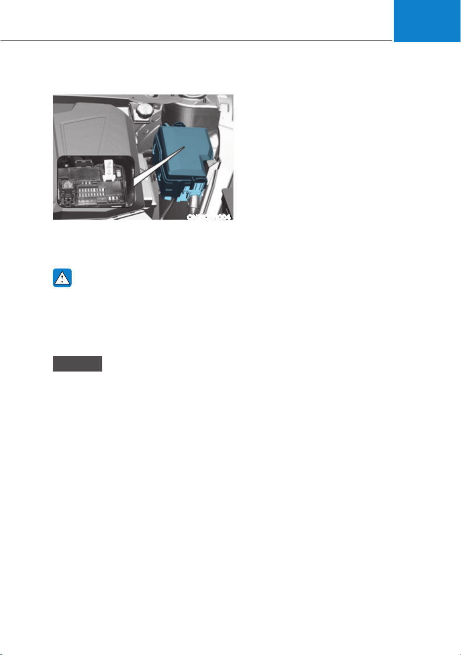
01
1-65
High Voltage cut-off Switch
ONE1Q011004
Pull down the yellow lever in the high
voltage cut-off switch to shut down high
voltage battery.
WARNING
Never disconnect the high voltage
cut-off switch except in an emergency
situation.
Serious problems may occur, such as
the vehicle will not start.
NOTICE
Putting the excessive force to the
switch lever while shutting down the
high voltage battery may severely
damage the high voltage cut-off switch.

2
2. Vehicle Information,
Consumer Information and
Reporting Safety Defects
Exterior Overview (I) ..........................................................................................2-2
Exterior Overview (II) .........................................................................................2-3
Interior Overview ............................................................................................. 2-4
Instrument Panel Overview (I) ......................................................................... 2-5
Instrument Panel Overview (II) ........................................................................ 2-6
Motor Compartment .........................................................................................2-7
Dimensions ........................................................................................................ 2-8
Electric Vehicle Specifications ......................................................................... 2-8
Bulb Wattage ..................................................................................................... 2-9
Tires and Wheels ..............................................................................................2-10
Air Conditioning System ...................................................................................2-11
Vehicle Weight and Luggage Volume .............................................................2-11
Available Front Trunk Weight ...........................................................................2-11
Recommended Lubricants and Capacities .................................................... 2-12
Vehicle Identification Number (VIN) .............................................................. 2-13
Vehicle Certification Label .............................................................................. 2-13
Tire Specification and Pressure Label ............................................................ 2-14
Motor Number ................................................................................................. 2-14
Air Conditioner Compressor Label ................................................................. 2-15
Refrigerant Label ............................................................................................. 2-15
Consumer Information .................................................................................... 2-16
Reporting Safety Defects ................................................................................ 2-17
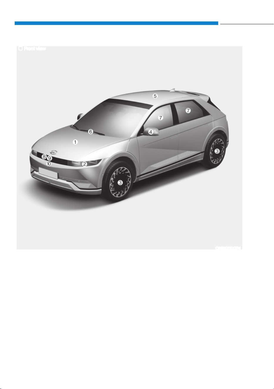
2-2
Vehicle Information, Consumer Information and Reporting Safety Defects
(;7(5,2529(59,(:ǣ,Ǥ
Front view
The actual shape may differ from the illustration.
ONE1011007N
1. Hood .......................................................5-73
2. Headlamp ..............................................9-49
3. Tires and wheels ................................... 9-22
4. Outside rearview mirror ....................... 5-59
5. Vision/Solar roof .......................... 5-67, 5-70
6. Front windshield wiper blades ...5-99, 9-16
7. Windows ............................................... 5-63
8. Front radar ...............................................7-4
9. Surround-front view camera ...............7-116
10. Charging display lamp .......................... 1-25
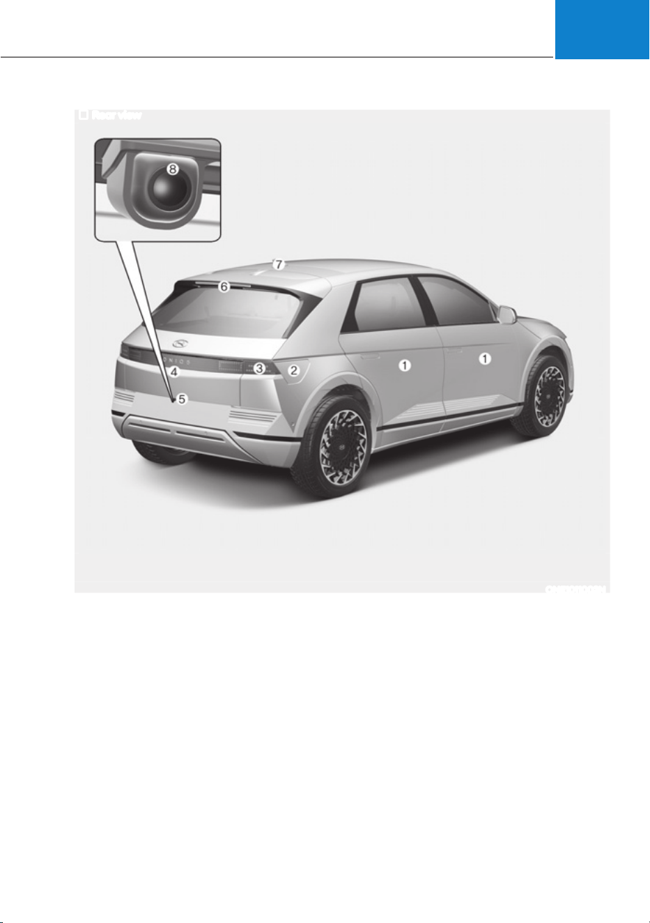
2-3
02
Rear view
The actual shape may differ from the illustration.
ONE1011002N
(;7(5,2529(59,(:ǣ,,Ǥ
1. Door ....................................................... 5-30
2. Electric charging door .......................... 5-84
3. Rear lamp ...............................................9-51
4. Liftgate ...................................................5-75
5. Liftgate open/close button ...................5-77
6. High mounted stop lamp ..................... 9-53
7. Antenna ................................................ 5-135
8. Rear view camera ................................. 7-113
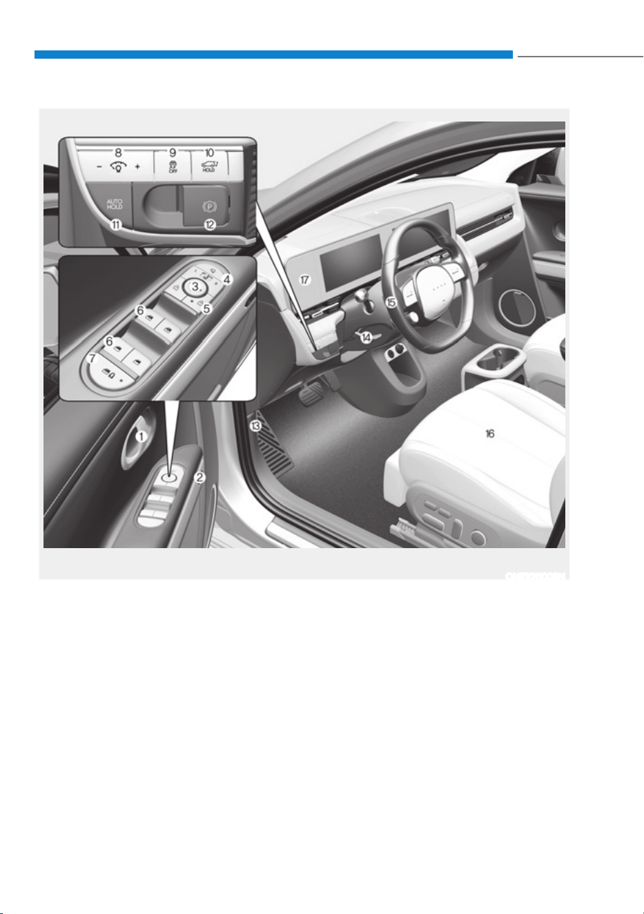
2-4
Vehicle Information, Consumer Information and Reporting Safety Defects
The actual shape may differ from the illustration.
ONE1011003N
1. Inside door handle ................................ 5-34
2. Integrated memory system .................5-40
3. Side view mirror control switch ...........5-60
4. Side view mirror folding button...........5-60
5. Central door lock switch ...................... 5-34
6. Power window switches ...................... 5-63
7. Power window lock button / ............... 5-65
Electronic child safety lock button .......5-37
8. Instrument panel illumination ............... 4-5
9. ESC (Electronic Stability Control) OFF
button .................................................... 6-37
10. Power liftgate open/close button ........5-78
11. AUTO Hold button ................................ 6-32
12. EPB (Electronic Parking Brake)
switch .....................................................6-27
13. Hood release lever .................................5-73
14. Steering wheel tilt/telescopic lever .... 5-45
15. Steering wheel ...................................... 5-44
16. Seat .......................................................... 3-3
17. Cluster fascia side panel .....................5-130
INTERIOR OVERVIEW
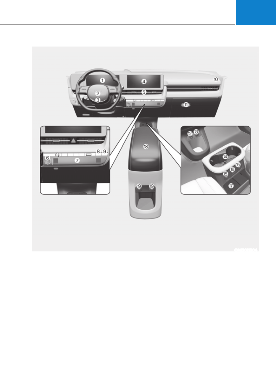
2-5
02
1. Instrument cluster .................................. 4-4
2. Horn .......................................................5-46
3. Driver’s front air bag ............................. 3-53
4. Infotainment system ...........................5-136
5. Hazard warning flasher button .............. 8-2
6. Start/Stop button ...................................6-4
7. Automatic climate control system .....5-102
8. Parking/View button ............................7-114
9. Parking Safety button .......................... 7-134
10. Passenger’s front air bag ..................... 3-53
11. Glove box ............................................. 5-123
12. USB port ............................................... 5-135
13. Power outlet ......................................... 5-125
14. Cup holder ........................................... 5-124
15. USB charger .........................................5-126
16. Wireless charging system ................... 5-127
17. Wireless charging system pad ............ 5-127
18. Center console..................................... 5-122
19. Rear seat USB charger ........................ 5-126
The actual shape may differ from the illustration.
ONE1011004
,167580(173$1(/29(59,(:ǣ,Ǥ
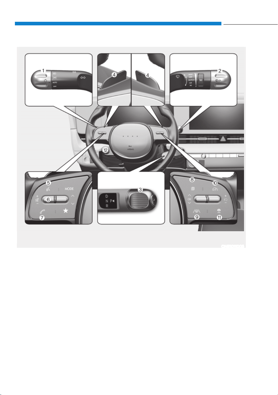
2-6
Vehicle Information, Consumer Information and Reporting Safety Defects
,167580(173$1(/29(59,(:ǣ,,Ǥ
The actual shape may differ from the illustration.
ONE1011005
1. Lighting control lever ...........................5-88
2. Wiper and washer control lever...........5-99
3. Rotary shifter(Rotary gear shift dial) .....6-9
4. Paddle shifter .........................................6-16
5. Voice recognition button .................... 5-137
6. Steering wheel audio controls ............ 5-135
7. Bluetooth wireless technology hands-free
button ................................................... 5-137
8. LCD display control .............................. 4-29
9. Lane Driving Assist button ........... 7-27, 7-97
10. Driving Assist button ..............................7-71
11. Vehicle Distance button .........................7-71
12. Drive mode button ............................... 6-47
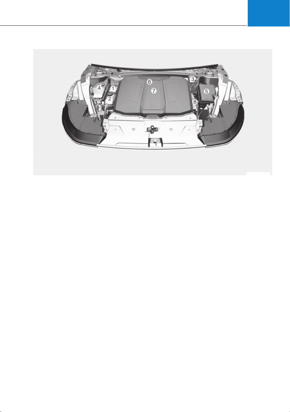
2-7
02
The actual motor compartment in the vehicle may differ from the illustration.
ONE1091001
1. Coolant reservoir ...................................9-12
2. Low Conductivity Water (LCW) ........... 9-12
Conductivity Water (LCW) coolant
reservoir .................................................9-12
3. Brake fluid reservoir ..............................9-13
4. Windshield washer fluid reservoir ........9-14
5. Fuse box ................................................ 9-36
6. Cabin air filter ........................................9-15
7. Front trunk .............................................5-74
8. Battery (12 volt) ......................................9-19
MOTOR COMPARTMENT

Vehicle Information, Consumer Information and Reporting Safety Defects
2-8
Items in (mm)
Overall length 182.48 (4,635)
Overall width 74.41 (1,890)
Overall height 63.0 (1,600) / 64.65 (1,642)*
Tread
Tire size Front Rear
19 in 64.49 (1,638) 64.84 (1,647)
20 in 64.09 (1,628) 64.49 (1,637)
Wheelbase 118.11 (3,000)
* : When measuring based on the shark fin antenna
ELECTRIC VEHICLE SPECIFICATIONS
Items
Standard type Extended type
2WD AWD 2WD AWD
Motor
Max. output (kW) 125 53+120 168 74+165
Max. torque (Nm) 350 255 + 350 350 255 + 350
Battery
(Lithium-ion)
Capacity (kWh) 58 58 77.4 77.4
Power output (kW) 195 195 253 253
Voltage (V) 523 523 697 697
Charger (OBC) Max. output (kW) 10.5 kW 10.5 10.9 10.9
OBC : On-Board Battery Chargers
DIMENSIONS

02
2-9
Light bulb Bulb type Wattage
Front
Headlamp
Low LED LED
High LED LED
Turn signal lamp
STD:PY21W
OPT:LED
STD:21W
OPT:LED
Parking lamp LED LED
Daytime Running Lamp (DRL) LED LED
Side marker LED LED
Front garnish lamp LED LED
Front trunk lamp LED LED
Rear
Stop lamp LED LED
Tail lamp LED LED
Turn signal lamp LED LED
Reverse lamp
STD : P21W
OPT : LED
STD : P21W
OPT : LED
Side marker LED LED
License plate lamp LED LED
Fog lamp LED LED
High mounted stop lamp LED LED
Interior
Front seat map and room lamp LED LED
Rear seat room lamp (without vision roof) LED LED
Rear seat personal lamp (with vision roof) LED LED
Vanity mirror lamp FESTOON 5W 5W
Glove box lamp LED LED
Door mood lamp LED LED
Luggage compartment lamp FESTOON 10W 10W
BULB WATTAGE

Vehicle Information, Consumer Information and Reporting Safety Defects
2-10
Items Tire size
Wheel
size
Battery
type
Inflation pressure psi (kPa)
Wheel lug nut
torque lbf-ft
(kgf-m, N-m)
Normal load
Maximum
load
Front Rear Front Rear
Full size
tire
235/55R 19 7.5J X 19
2WD
Standard
36
(250)
36
(250)
36
(250)
36
(250)
79~94
(11~13, 108~127)
235/55R 19 7.5J X 19
2WD
Extended
38
(260)
38
(260)
38
(260)
38
(260)
235/55R 19 7.5J X 19
AWD
Extended
36
(250)
36
(250)
36
(250)
36
(250)
255/45R20 8.5J X 20
AWD
Extended
34
(235)
34
(235)
34
(235)
34
(235)
NOTICE
ś Ambient temperature affects the tire pressure (about 1 psi (7 kPa) for every
12°F (7°C) change). If colder temperatures are anticipated, it is permissible to
increase cold tire inflation pressure by up to 3 psi (20 kPa) over the specification.
If extreme temperature changes are expected, be sure to check and adjust tire
pressure accordingly.
ś Tire inflation pressure decreases with higher elevation, and increases with lower
elevation (about 2.4 psi (10 kPa) for every mile (or kilometer) elevation change).
Be sure to check and adjust tire pressure accordingly when driving through
changing elevations.
ś Do not exceed the maximum inflation pressure, as found on the sidewall of the
tire(s).
CAUTION
When replacing tires, ALWAYS use the same size, type, brand, construction and
tread pattern supplied with the vehicle. If not, it can damage the related parts or
make it work irregularly.
TIRES AND WHEELS

02
2-11
Item Weight of volume Classification
Refrigerant
Heat pump 900±25g (32±0.9 oz.)
R-1234yf
Without heat pump 700±25g (25±0.9 oz.)
Compressor lubricant
Heat pump 180±10 g (6.35±0.35 oz.)
POE J639
Without heat pump 150±10 g (5.29±0.35 oz.)
Contact an authorized HYUNDAI dealer for more details.
VEHICLE WEIGHT AND LUGGAGE VOLUME
Gross vehicle weight
Luggage volume
Standard type Extended type
2WD: 5225 lbs. (2370 kg)
AWD: 5467 lbs. (2480 kg)
2WD: 5357 lbs. (2430 kg)
4WD: 5600 lbs. (2540 kg)
FXIWŢ
AVAILABLE FRONT TRUNK WEIGHT
2WD 55 lbs (25 kg)
4WD 25 lbs (10 kg)
Available front trunk weight depends on the specifications.
AIR CONDITIONING SYSTEM

Vehicle Information, Consumer Information and Reporting Safety Defects
2-12
To help achieve proper vehicle performance and durability, use only lubricants of the
proper quality.
These lubricants and fluids are recommended for use in your vehicle.
Lubricant Volume Classification
Reduction gear fluid
2WD Rear
3.6~3.7 US qt.
aŢ
HK ATF 65 SP4M-1
4WD
Front
3.4~3.5 US qt.
aŢ
Rear
3.6~3.7 US qt.
aŢ
Coolant
Standard type
with heat
pump
2WD 86TWŢ
Designated coolant
water for electric
vehicles
4WD 86TWŢ
without heat
pump
2WD 86TWŢ
4WD 86TWŢ
Extended type
with heat
pump
2WD 86TWŢ
4WD 86TWŢ
without heat
pump
2WD 86TWŢ
4WD 86TWŢ
LCW
Coolant
Standard type
with heat
pump
2WD 86TWŢ
4WD 86TWŢ
without heat
pump
2WD 86TWŢ
4WD 86TWŢ
Extended type
with heat
pump
2WD 86TWŢ
4WD 86TWŢ
without heat
pump
2WD 86TWŢ
4WD 86TWŢ
Brake fluid As required
SAE J1704 DOT-
4 LV, FMVSS 116
DOT-4, ISO 4925
CLASS-6
RECOMMENDED LUBRICANTS AND CAPACITIES
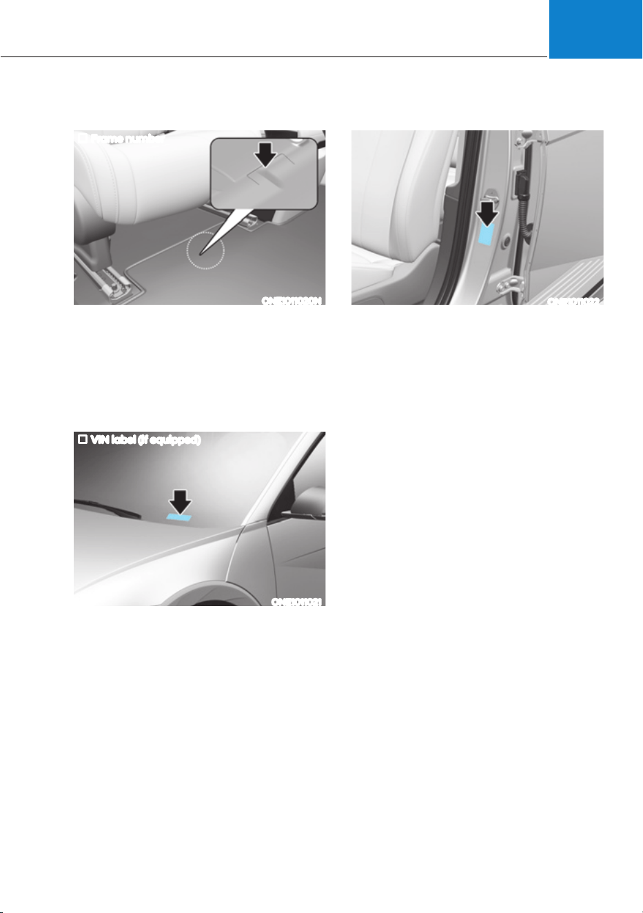
02
2-13
VEHICLE IDENTIFICATION
180%(5ǣ9,1Ǥ
Frame number
ONE1011020N
The vehicle identification number (VIN)
is the number used in registering your
vehicle and in all legal matters pertaining
to its ownership, etc.
The number is punched on the floor
under the right front seat. To check the
number, open the cover.
VIN label (if equipped)
ONE1011021
The VIN is also on a plate attached to
the top of the left side dashboard. The
number on the plate can easily be seen
through the windshield from outside.
VEHICLE CERTIFICATION
LABEL
ONE1011022
The vehicle certification label attached
on the driver’s (or front passenger’s)
side center pillar gives the vehicle
identification number (VIN).
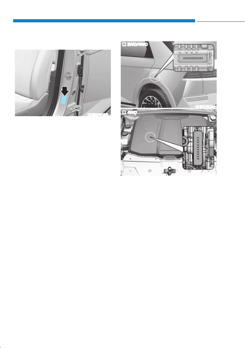
Vehicle Information, Consumer Information and Reporting Safety Defects
2-14
TIRE SPECIFICATION AND
PRESSURE LABEL
ONE1011025L
The tires supplied on your new
vehicle are chosen to provide the best
performance for normal driving.
The tire label located on the driver’s
side center pillar gives the tire pressures
recommended for your vehicle.
MOTOR NUMBER
2WD/4WD
ONE1011024
4WD
ONE1011023
The motor numbers can be checked at
the bottom of the vehicle.
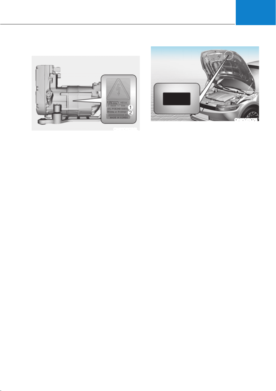
02
2-15
AIR CONDITIONER
COMPRESSOR LABEL
ONE1011026L
A compressor label informs you the type
of compressor your vehicle is equipped
with such as model, supplier part
number, production number, refrigerant
(1) and refrigerant oil (2).
REFRIGERANT LABEL
ONE1051075
The refrigerant label provides
information such as refrigerant type and
amount. (R-1234yf)

Vehicle Information, Consumer Information and Reporting Safety Defects
2-16
This consumer information has been prepared in accordance with regulations issued
by the National Highway Traffic Safety Administration of the U.S. Department of
Transportation.Your HYUNDAI dealer will help answer any questions you may have as
you read this information.
HYUNDAI motor vehicles are designed and manufactured to meet or exceed all
applicable safety standards.
For your safety, however, we strongly urge you to read and follow all directions in
this Owner’s Manual, particularly the information under the headings “NOTICE”,
“CAUTION” and “WARNING”.
If, after reading this manual, you have any questions regarding the operation of your
vehicle, please contact the Hyundai Customer Care Center.
Hyundai Customer Care
P.O. Box 20850
Fountain Valley, CA 92728
800-633-5151
consumeraff[email protected]
Hyundai’s Customer Care representatives are available Monday through Friday,
between the hours of 6:00 AM and 5:00 PM PST
and Saturday between 6:30 AM and 3:00 PM PST (English).
For Customer Care assistance in Spanish or Korean, representatives are available
Monday through Friday between 6:30 AM and 3:00 PM PST.
CONSUMER INFORMATION

02
2-17
If you believe that your vehicle has a defect which could cause a crash or
could cause injury or death, you should immediately inform the National
Highway Traffic Safety Administration (NHTSA) in addition to notifying
HYUNDAI MOTOR AMERICA.
To contact NHTSA, you may call the Vehicle Safety Hotline toll-free at 1-888-
327-4236 (TTY: 1-800-424-9153);
go to http://www.safercar.gov;
download the SaferCar mobile application;
or write to: Administrator, NHTSA
1200 New Jersey Ave, SE,
West Building Washington, D.C. 20590.
You can also obtain other information about motor vehicle safety from
http://www.safercar.gov.
If NHTSA receives similar complaints, it may open an investigation, and if it
finds that a safety defect exists in a group of vehicles, it may order a recall and
remedy campaign. However, NHTSA cannot become involved in individual
problems between you, your dealer, or HYUNDAI MOTOR AMERICA.
REPORTING SAFETY DEFECTS

3
3. Seats & Safety System
Important Safety Precautions ...........................................................................3-2
Always Wear Your Seat Belt ......................................................................................... 3-2
Restrain All Children .....................................................................................................3-2
Air Bag Hazards ............................................................................................................ 3-2
Driver Distraction ......................................................................................................... 3-2
Control Your Speed ...................................................................................................... 3-2
Keep Your Vehicle In Safe Condition ........................................................................... 3-2
Seats .................................................................................................................. 3-3
Safety Precautions .......................................................................................................3-6
Front Seats ....................................................................................................................3-7
Rear Seats ................................................................................................................... 3-16
Head Restraint ............................................................................................................3-20
Seat Warmers .............................................................................................................3-24
Air Ventilation Seats ...................................................................................................3-26
Advanced Rear Occupant Alert (ROA) ......................................................................3-28
Seat Belts ......................................................................................................... 3-29
Seat Belt Safety Precautions .....................................................................................3-29
Seat Belt Warning Light .............................................................................................3-30
Seat Belt Restraint System .........................................................................................3-31
Additional Seat Belt Safety Precautions ...................................................................3-36
Care of Seat Belts .......................................................................................................3-38
Child Restraint System (CRS) ......................................................................... 3-39
Children Always in the Rear .......................................................................................3-39
Selecting a Child Restraint System (CRS) ................................................................ 3-40
Installing a Child Restraint System (CRS) ................................................................. 3-41
Air Bag - Supplemental Restraint System .....................................................3-49
Where are the Air Bags? ............................................................................................. 3-51
How does the Air Bags System Operate? .................................................................3-54
What to Expect After an Air Bag Inflates ..................................................................3-58
Occupant Classification System (OCS) .....................................................................3-59
Why didn’t my air bag go off in a collision? ..............................................................3-65
SRS Care .....................................................................................................................3-70
Additional Safety Precautions ....................................................................................3-71
Air Bag Warning Labels ...............................................................................................3-71

Seats & Safety System
3-2
You will find many safety precautions
and recommendations throughout this
section, and throughout this manual.
The safety precautions in this section are
among the most important.
Always Wear Your Seat Belt
A seat belt is your best protection in all
types of accidents. Air bags are designed
to supplement seat belts, not to replace
them. So even though your vehicle is
equipped with air bags, ALWAYS make
sure you and your passengers wear your
seat belts, and wear them properly.
Restrain All Children
All children under age 13 should ride
in your vehicle properly restrained in a
rear seat, not the front seat. Infants and
small children should be restrained in
an appropriate Child Restraint System.
Larger children should use a booster
seat with the lap/shoulder belt until they
can use the seat belt properly without a
booster seat.
Air Bag Hazards
While air bags can save lives, they can
also cause serious or fatal injuries to
occupants who sit too close to them, or
who are not properly restrained. Infants,
young children, and short adults are at
the greatest risk of being injured by an
inflating air bag. Follow all instructions
and warnings in this manual.
Driver Distraction
Driver distraction presents a serious and
potentially deadly danger, especially for
inexperienced drivers. Safety should be
the first concern when behind the wheel
and drivers need to be aware of the wide
array of potential distractions, such as
drowsiness, reaching for objects, eating,
personal grooming, other passengers,
and using mobile phones.
Drivers can become distracted when
they take their eyes and attention off
the road or their hands off the wheel to
focus on activities other than driving.
To reduce your risk of distraction and an
accident:
ś Set up your mobile devices (for
example, MP3 players, phones,
navigation units, etc.) ONLY when
your vehicle is parked or safely
stopped.
ś ONLY use your mobile device when
allowed by laws and conditions permit
safe use. NEVER text or email while
driving. Most countries have laws
prohibiting drivers from texting. Some
countries and cities also prohibit
drivers from using handheld phones.
ś NEVER let the use of a mobile device
distract you from driving. You have a
responsibility to your passengers and
others on the road to always drive
safely, with your hands on the wheel
as well as your eyes and attention on
the road.
Control Your Speed
Excessive speed is a major factor in crash
injuries and deaths. Generally, the higher
the speed, the greater the risk, but
serious injuries can also occur at lower
speeds. Never drive faster than is safe
for current conditions, regardless of the
maximum speed posted.
Keep Your Vehicle In Safe
Condition
Having a tire blowout or a mechanical
failure can be extremely hazardous. To
reduce the possibility of such problems,
check your tire pressures and condition
frequently, and perform all regularly
scheduled maintenance.
IMPORTANT SAFETY PRECAUTIONS
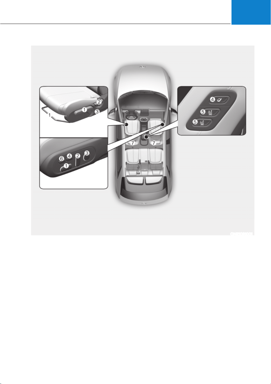
3-3
03
Front seat
(1) Seat sliding forward or
rearward/Cushion height/Seat
cushion(Relaxation comfort) angle
(2) Seatback angle
(3) Lumbar support
(4) Relaxation comfort seat switch
(5) Rear seat control switch
(6) Leg support
(7) Head restraint
à Relaxation: Relax + Position
SEATS
The actual shape may differ from the illustration.
ONE1031001
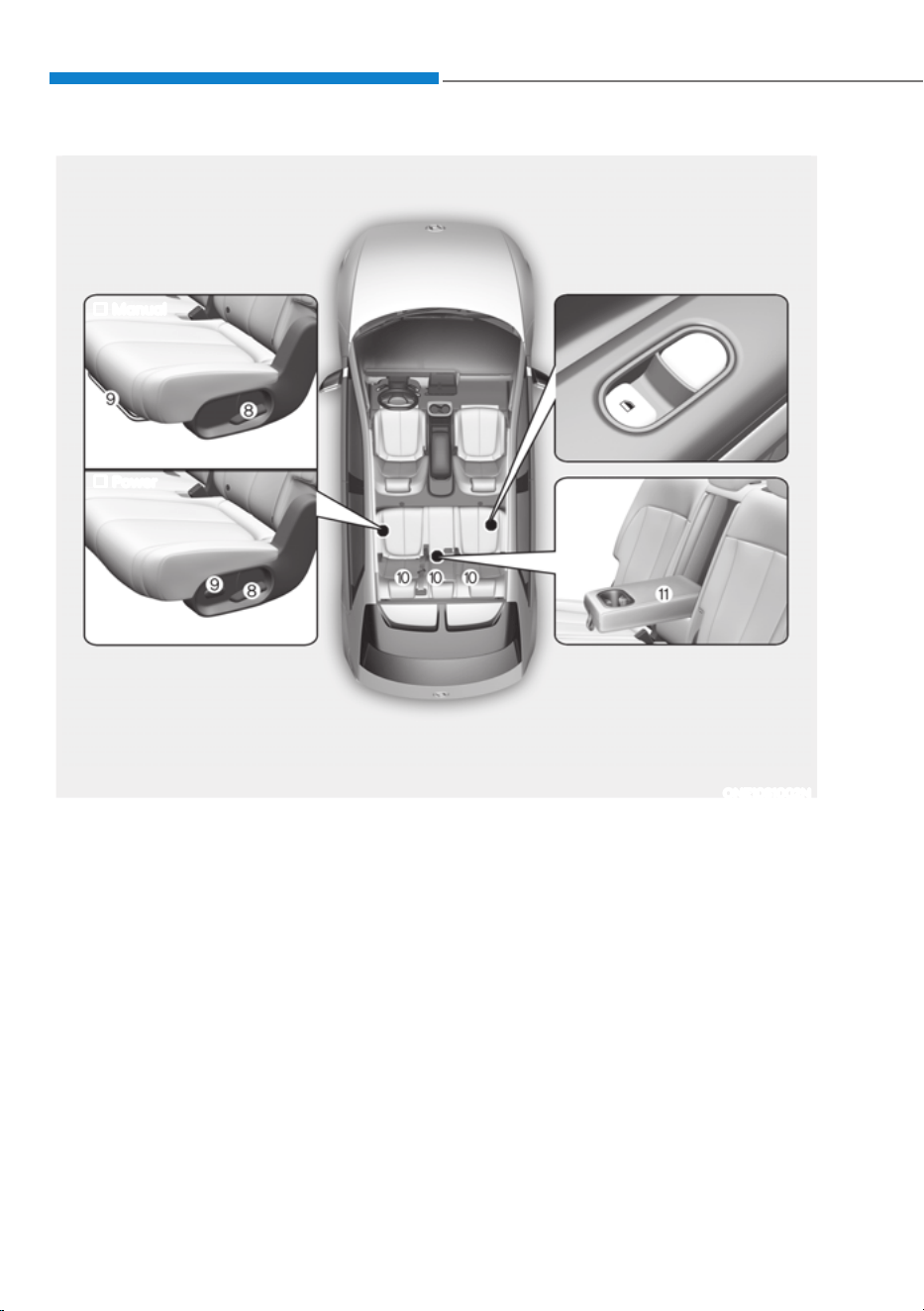
3-4
Seats & Safety System
The actual shape may differ from the illustration.
ONE1031002N
Rear seat
(8) Seatback angle / Seatback folding
lever
(9) Seat slide forward or rearward
(10)
Head restraint
(11)
Armrest
Manual
Power
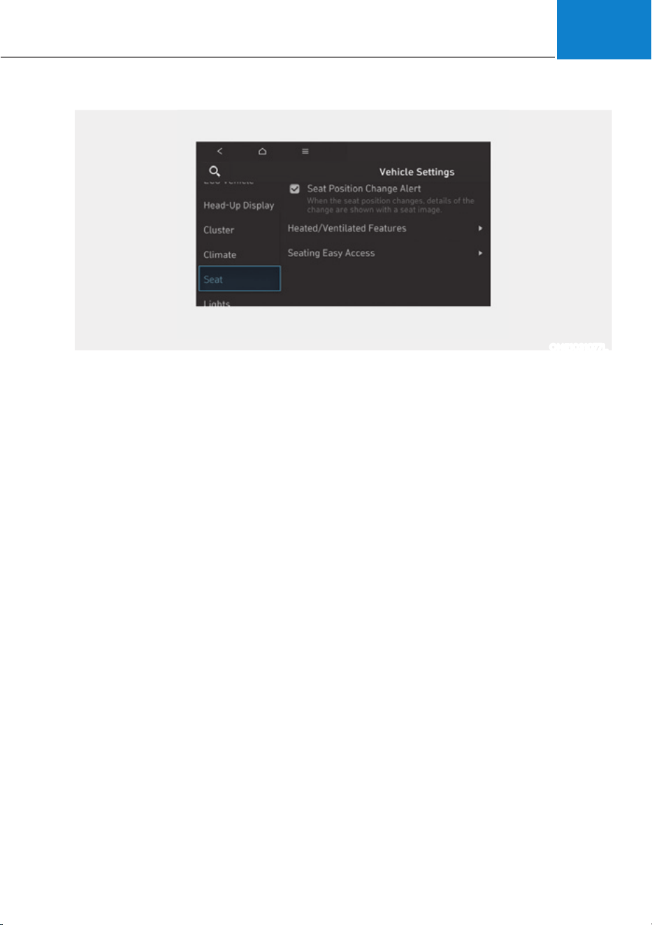
03
3-5
ONE1031077L
Infotainment system
6HOHFWœ6HWXSƟ9HKLFOH6HWWLQJVƟ6HDWŔIURPWKH6HWWLQJVPHQXLQWKHLQIRWDLQPHQW
system screen, you may use various convenience functions.
ś Seat position change alert : When the seat position changes, details of the change
are shown with a seat image.
ś Heated/Ventilated features
- Auto. Controls That Use Climate Control Settings (for driver’s seat) : The seat
temperature is automatically controlled.
ś Seating easy access
- Steering wheel easy access : Moves the steering wheel when the driver enters or
leaves the vehicle.
- Driver seat easy access : The distance (Normal/Extended/Off) the seat
automatically moves when the driver enters or leaves the vehicle may be
selected.
For detailed information, refer to the separately supplied infotainment system
manual.

Seats & Safety System
3-6
Information
The information provided may differ
depending on which functions are
applicable to your vehicle.
Safety Precautions
Adjusting the seats so that you are sitting
in a safe and comfortable position plays
an important role for the safety of the
driver and passengers, as much as seat
belts and air bags when in an accident.
WARNING
Do not use a cushion that reduces
friction between the seat and the
passenger. The passenger’s hips may
slide under the lap portion of the seat
belt during an accident or a sudden
stop.
Serious or fatal internal injuries could
result because the seat belt cannot
operate properly.
Air bags
You can take steps to reduce the risk
of being injured by an inflating air bag.
Sitting too close to an air bag greatly
increases the risk of injury in the event
the air bag inflates. Move your seat as
far back as possible from front air bags,
while still maintaining control of the
vehicle.
WARNING
To reduce the risk of serious injury or
death from an inflating air bag, take the
following precautions:
ś Adjust the driver’s seat as far to the
rear as possible maintaining the
ability to control the vehicle.
ś Adjust the front passenger seat as far
to the rear as possible.
ś Hold the steering wheel by the rim
with hands at the 9 o’clock and 3
o’clock positions to minimize the risk
of injuries to your hands and arms.
ś NEVER place anything or anyone
between you and the air bag.
ś Do not allow the front passenger to
place feet or legs on the dashboard
to minimize the risk of leg injuries.

03
3-7
Seat belts
Always fasten your seat belt before
starting any trip. At all times, passengers
should sit upright and be properly
restrained. Infants and small children
must be restrained in appropriate Child
Restraint Systems. Children who have
outgrown a booster seat and adults must
be restrained using the seat belts.
WARNING
Take the following precautions when
adjusting your seat belt:
ś NEVER use one seat belt for more
than one occupant.
ś Always position the seatback upright
with the lap portion of the seat belt
snug and low across the hips.
ś NEVER allow children or small infants
to ride on a passenger’s lap.
ś Do not route the seat belt across your
neck, across sharp edges, or reroute
the shoulder strap away from your
body.
ś Do not allow the seat belt to become
caught or jammed.
Front Seats
WARNING
Take the following precautions when
adjusting your seat:
ś NEVER attempt to adjust the seat
while the vehicle is moving. The seat
could respond with unexpected
movement and may cause loss
of vehicle control resulting in an
accident.
ś Do not place anything under the
front seats. Loose objects in the
driver’s foot area could interfere
with the operation of the foot pedals,
causing an accident.
ś Do not allow anything to interfere
with the normal position and proper
locking of the seatback.
ś Do not place a cigarette lighter on
the floor or seat. When you operate
the seat, gas may exit out of the
lighter causing a fire.
ś Use extreme caution when picking
up small objects trapped under the
seats or between the seat and the
center console. Your hands might be
cut or injured by the sharp edges of
the seat mechanism.
ś If there are occupants in the rear
seats, be careful while adjusting the
front seat position.
ś Make sure that the seat is locked in
place after the adjustment. If not,
the seat might move unexpectedly
resulting in an accident.
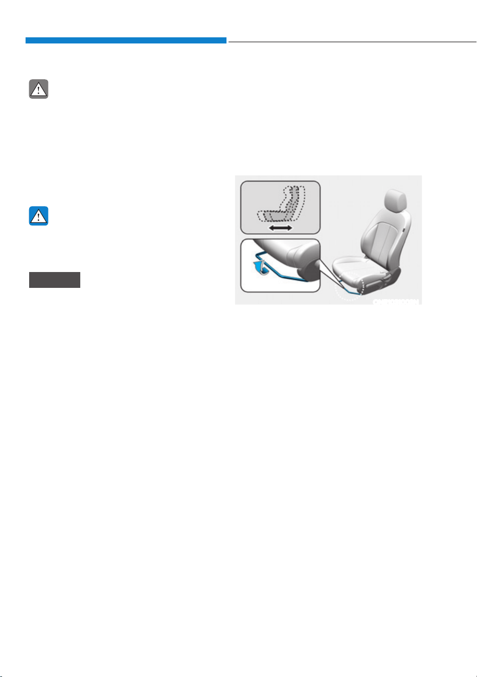
Seats & Safety System
3-8
CAUTION
To prevent injury:
ś Do not adjust your seat while
wearing your seat belt. Moving the
seat cushion forward may cause
strong pressure on your abdomen.
ś Do not allow your hands or fingers to
get caught in the seat mechanisms
while the seat is moving.
WARNING
NEVER allow children in the vehicle
unattended. The power seats are
operable when the vehicle is turned off.
NOTICE
To prevent damage to the seats:
ś Always stop adjusting the seats when
the seat has been adjusted as far
forward or rearward as possible.
ś Do not adjust the seats longer than
necessary when the vehicle is turned
off. This may result in unnecessary
battery drain.
ś Do not operate two or more seats at
the same time. This may result in an
electrical malfunction.
Manual adjustment (if equipped)
The front seat can be adjusted by using
the levers located underneath the seat
cushion. Before driving, adjust the seat
to the proper position so that you can
easily control the steering wheel, foot
pedals and controls on the instrument
panel.
ONE1031003N
Forward and rearward adjustment
To move the seat forward or rearward:
1. Pull up the seat slide adjustment lever
and hold it.
2. Slide the seat to the position you
desire.
3. Release the lever and make sure the
seat is locked in place. Move forward
and rearward without using the lever.
If the seat moves, it is not locked
properly.
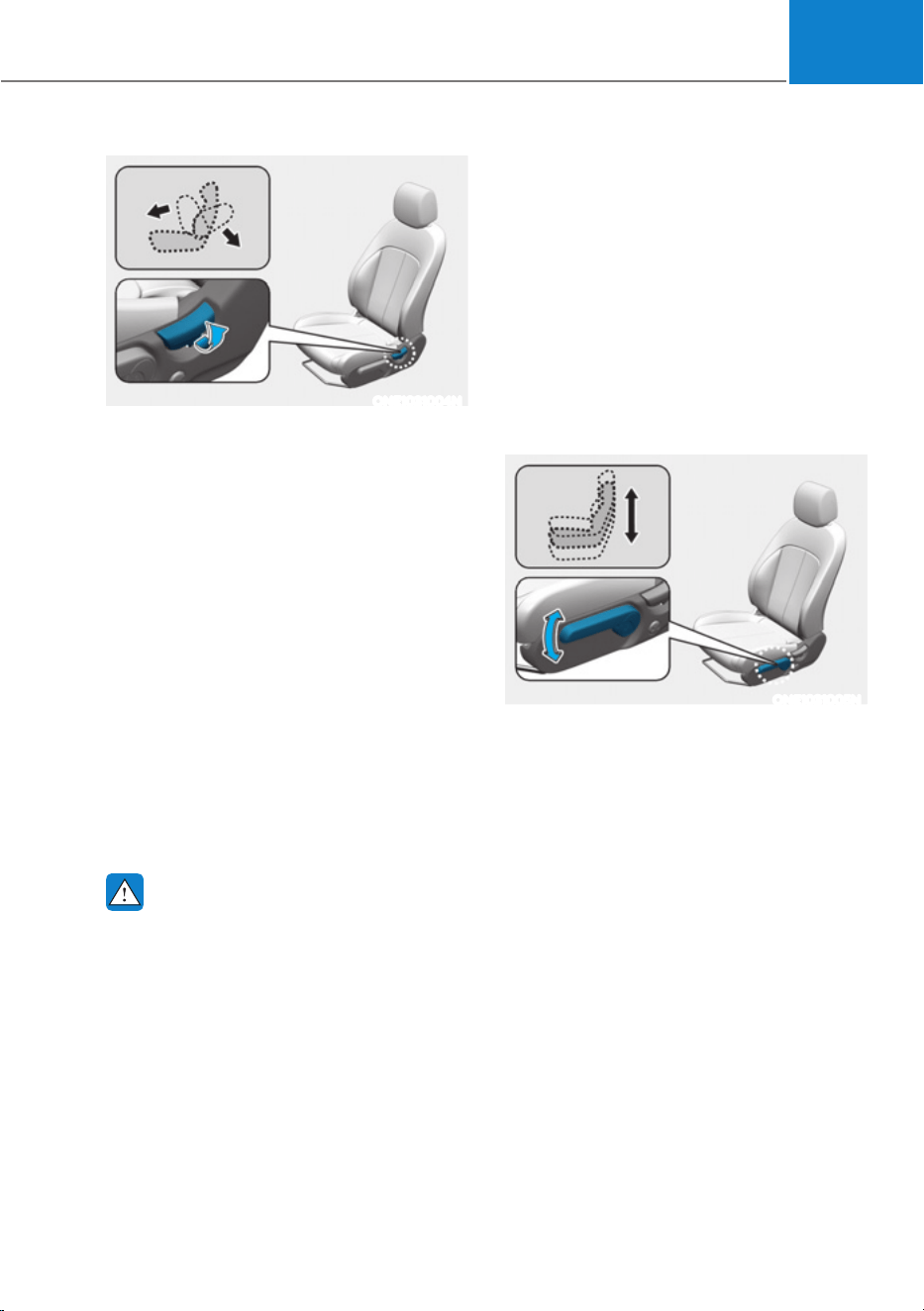
03
3-9
ONE1031004N
Seatback angle
To recline the seatback:
1. Lean forward slightly and lift up the
seatback lever.
2. Carefully lean back on the seat and
adjust the seatback to the position
you desire.
3. Release the lever and make sure the
seatback is locked in place. (The lever
MUST return to its original position for
the seatback to lock.)
Reclining seatback
Sitting in a reclined position when the
vehicle is in motion can be dangerous.
Even when buckled up, the protections
of your restraint system (seat belts
and/or air bags) is greatly reduced by
reclining your seatback.
WARNING
NEVER ride with a reclined seatback
when the vehicle is moving.
Riding with a reclined seatback
increases your chance of serious or fatal
injuries in the event of a collision or
sudden stop.
Drivers and passengers should ALWAYS
sit well back in their seats, properly
belted, and with the seatbacks upright.
Seat belts must be snug against your
hips and chest to work properly. When
the seatback is reclined, the shoulder
belt cannot do its job because it will not
be snug against your chest. Instead,
it will be in front of you. During an
accident, you could be thrown into the
seat belt, causing neck or other injuries.
The more the seatback is reclined,
the greater chance the passenger’s
hips will slide under the lap belt or the
passenger’s neck will strike the shoulder
belt.
ONE1031005N
Seat height
To change the height of the seat cushion:
ś Push down the lever several times, to
lower the seat cushion.
ś Pull up the lever several times, to raise
the seat cushion.
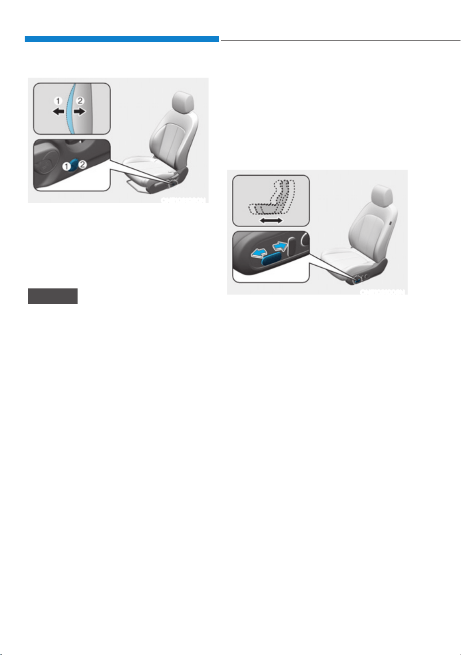
Seats & Safety System
3-10
ONE1031090N
Lumbar support
To adjust the lumbar support:
ś Press the front portion of the switch
(1) to increase the support or the rear
portion of the switch (2) to decrease
the support.
NOTICE
Do not continue to operate the lumbar
support when the lumbar support
provides its maximum support. Damage
to the lumbar support motor could
occur.
Power adjustment (if equipped)
The front seat can be adjusted by using
the control switches located on the
outside of the seat cushion. Before
driving, adjust the seat to the proper
position so that you can easily control
the steering wheel, foot pedals and
controls on the instrument panel.
ONE1031006N
Forward and rearward adjustment
To move the seat forward or rearward:
1. Push the control switch forward or
rearward.
2. Release the switch once the seat
reaches the desired position.
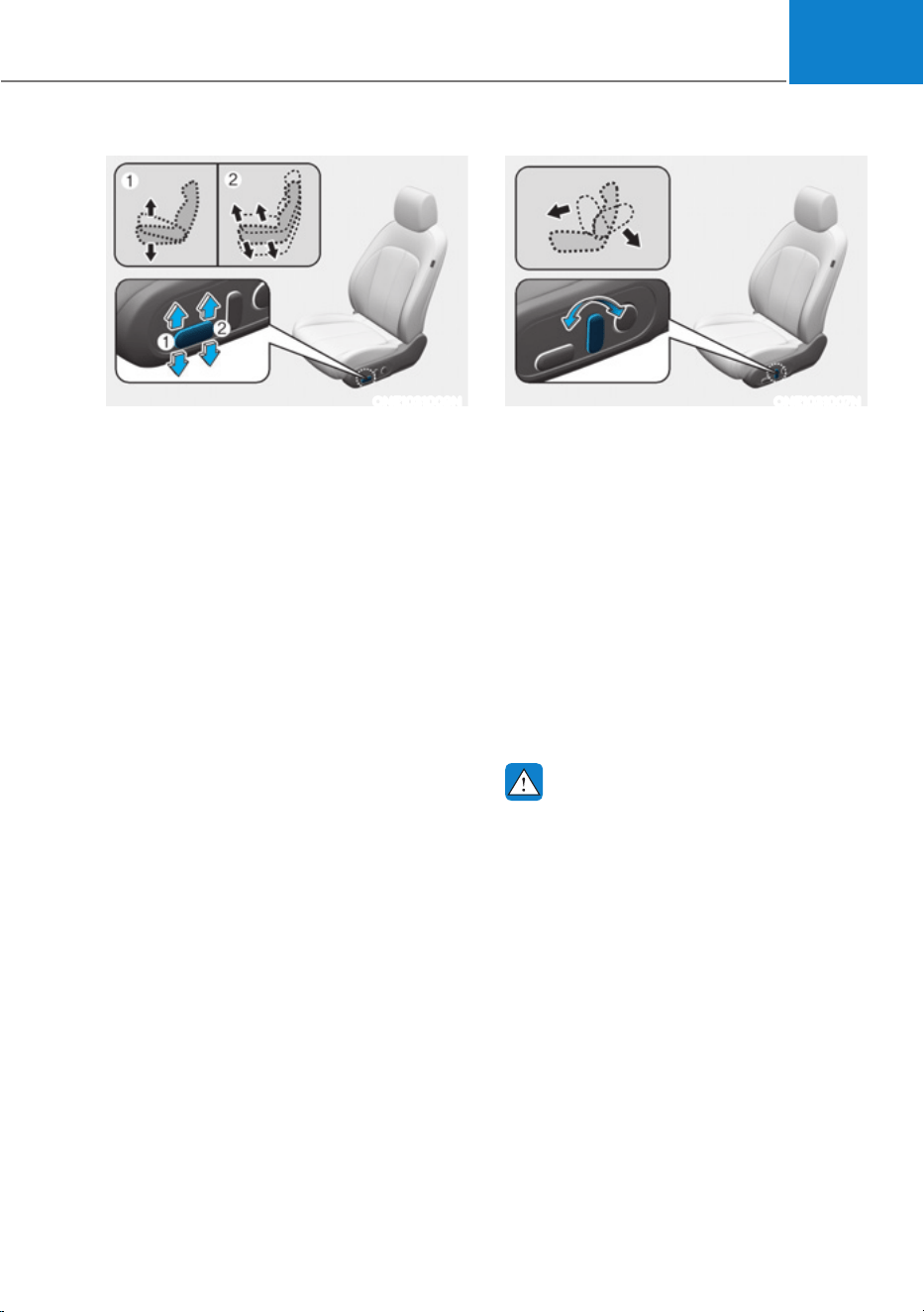
03
3-11
ONE1031009N
Seat cushion tilt/height adjustment
ś Seat cushion tilt (1)
To change the angle of the front part of
the seat cushion:
Push the front portion of the control
switch up to raise or down to lower the
front part of the seat cushion.
Release the switch once the seat reaches
the desired position.
ś Seat height (2)
To change the height of the seat cushion:
Push the rear portion of the control
switch up to raise or down to lower the
height of the seat cushion.
Release the switch once the seat reaches
the desired position.
ONE1031007N
Seatback angle adjustment
To recline the seatback:
1. Push the control switch forward or
rearward.
2. Release the switch once the seatback
reaches the desired position.
Reclining seatback
Sitting in a reclined position when the
vehicle is in motion can be dangerous.
Even when buckled up, the protections
of your restraint system (seat belts and
air bags) is greatly reduced by reclining
your seatback.
WARNING
NEVER ride with a reclined seatback
when the vehicle is moving.
Riding with a reclined seatback
increases your chance of serious or fatal
injuries in the event of a collision or
sudden stop.
Driver and passengers should ALWAYS
sit well back in their seats, properly
belted, and with the seatbacks upright.
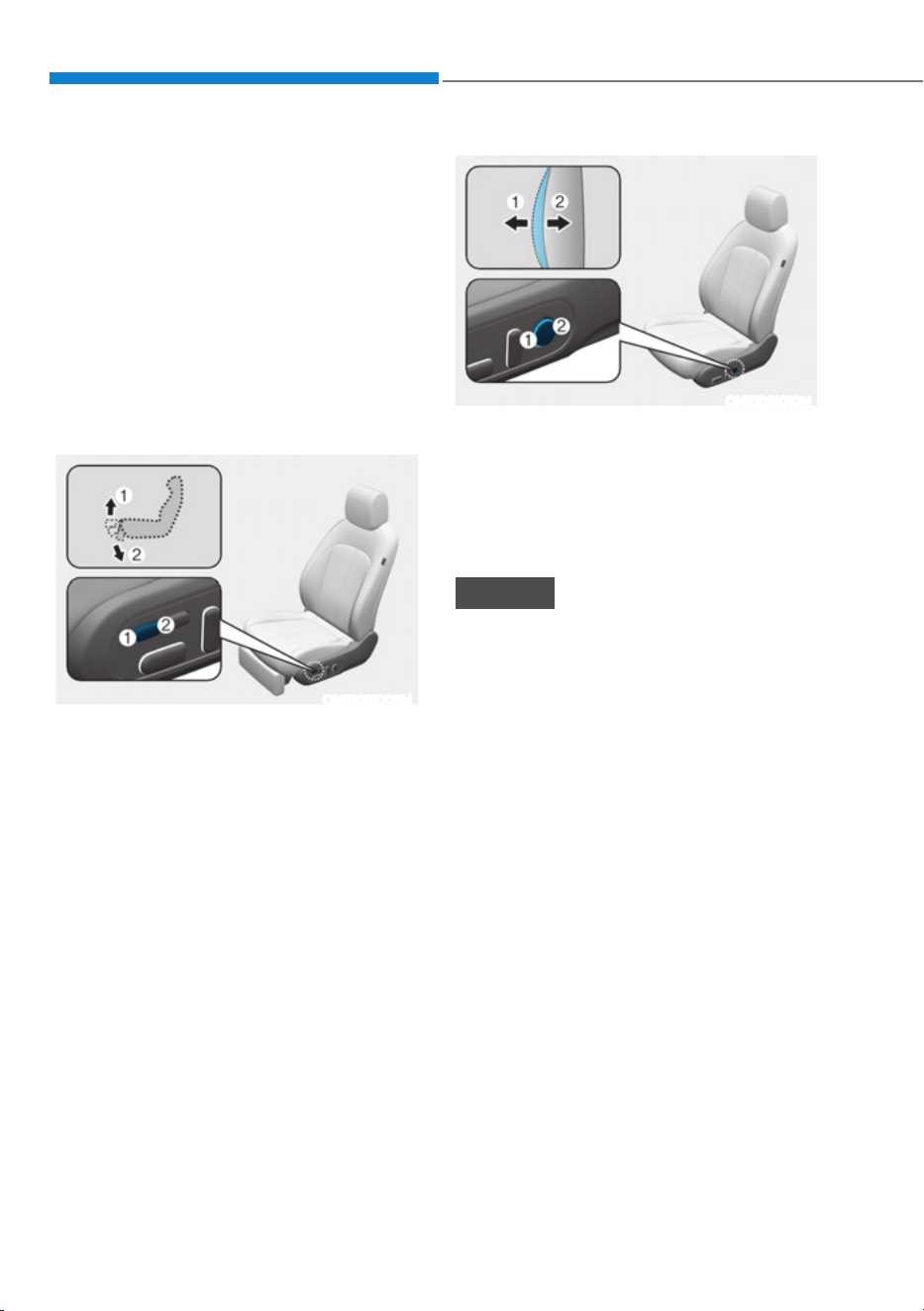
Seats & Safety System
3-12
Seat belts must be snug against your
hips and chest to work properly. When
the seatback is reclined, the shoulder
belt cannot do its job because it will not
be snug against your chest. Instead,
it will be in front of you. During an
accident, you could be thrown into the
seat belt, causing neck or other injuries.
The more the seatback is reclined,
the greater chance the passenger’s
hips will slide under the lap belt or the
passenger’s neck will strike the shoulder
belt.
ONE1031008N
Leg support adjustment (if equipped)
1. Press the front portion of the switch
(1) to raise the leg support.
2. Press the rear portion of the switch (2)
to lower the leg support.
ONE1031010N
Lumbar support
To adjust the lumbar support:
ś Press the front portion of the switch
(1) to increase support or the rear
portion of the switch (2) to decrease
support.
NOTICE
Do not continue to operate the lumbar
support when the lumbar support
provides its maximum support. Damage
to the lumbar support motor could
occur.
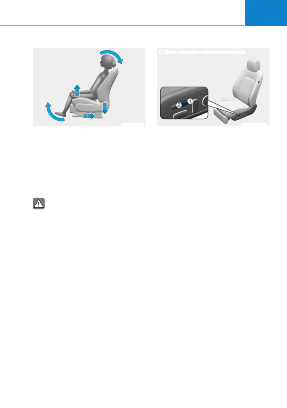
03
3-13
ONE1031011
Relaxation comfort seat (for Driver’s seat,
if equipped)
Relaxation comfort seats help distribute
body pressure and concentrated weight
on specific body parts that occur while
sitting in the same position for a long
period of time. The seat helps relieve
fatigue and discomfort by providing the
optimal sit position.
CAUTION
Take the following precautions when
using the relaxation comfort seat:
ś Do not use the relaxation comfort
seat while the vehicle is moving.
Using the comfort seat could
increase the risk of injuries in the
event of a collision or sudden stop.
ś Do not use the relaxation comfort
seat when the luggage or other
objects are placed at the rear seat.
ś Do not use the relaxation comfort
seat while the vehicle is moving. Seat
belts may not operate normally due
to the lack of adherence between the
shoulder belts and the body.
ś Do not use the relaxation comfort
seat when the rear seats are not in
the rearmost position and upright.
Driver relaxation comfort seat switch
ONE1031013N
To activate relaxation comfort seat
Press the switch (1) more than 0.5
seconds, an alarm appears on the
infotainment screen. Then, press the
switch (1) again for more than 0.5
seconds.
If the switch is not pressed within
5 seconds after the alarm appears,
relaxation comfort seat will not be
activated.
When relaxation comfort seat is
activated:
1. The seat cushion will be moved
forward or rearward automatically.
2. The seat cushion, seatback angle and
leg support will be adjusted.
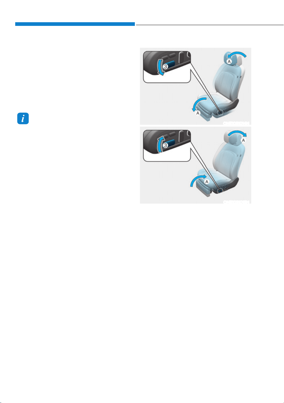
Seats & Safety System
3-14
In the following cases, an alarm appears
on when the infotainment screen is on
and the relaxation comfort seat will be
deactivated.
ś When the gear is not in P (Parking).
ś When the vehicle is moving more than
1.8 mph (3 km/h).
ś When the rear seat belt is fastened
Information
When relaxion comfort seat cannot be
operated, try to reset Integrated Memory
System. If relaxation comfort seat does
not operate even after Integrated Memory
System is reset, contact an authorized
HYUNDAI dealer.
ONE1031014N
ONE1031015N
[A] : Moves simultaneously
You can adjust moves simultaneously
the seat directly by using the seat
adjustment switches (3).
Push down the forward part of the switch
(3) to move back the chair to the original
position.
Pull up the forward part of the switch
(3) to adjust the seat to the relaxation
comfort position.
Even when the relaxation comfort seat
is operated by others, the additional
adjustment is possible by pressing
relaxation comfort seat switches.
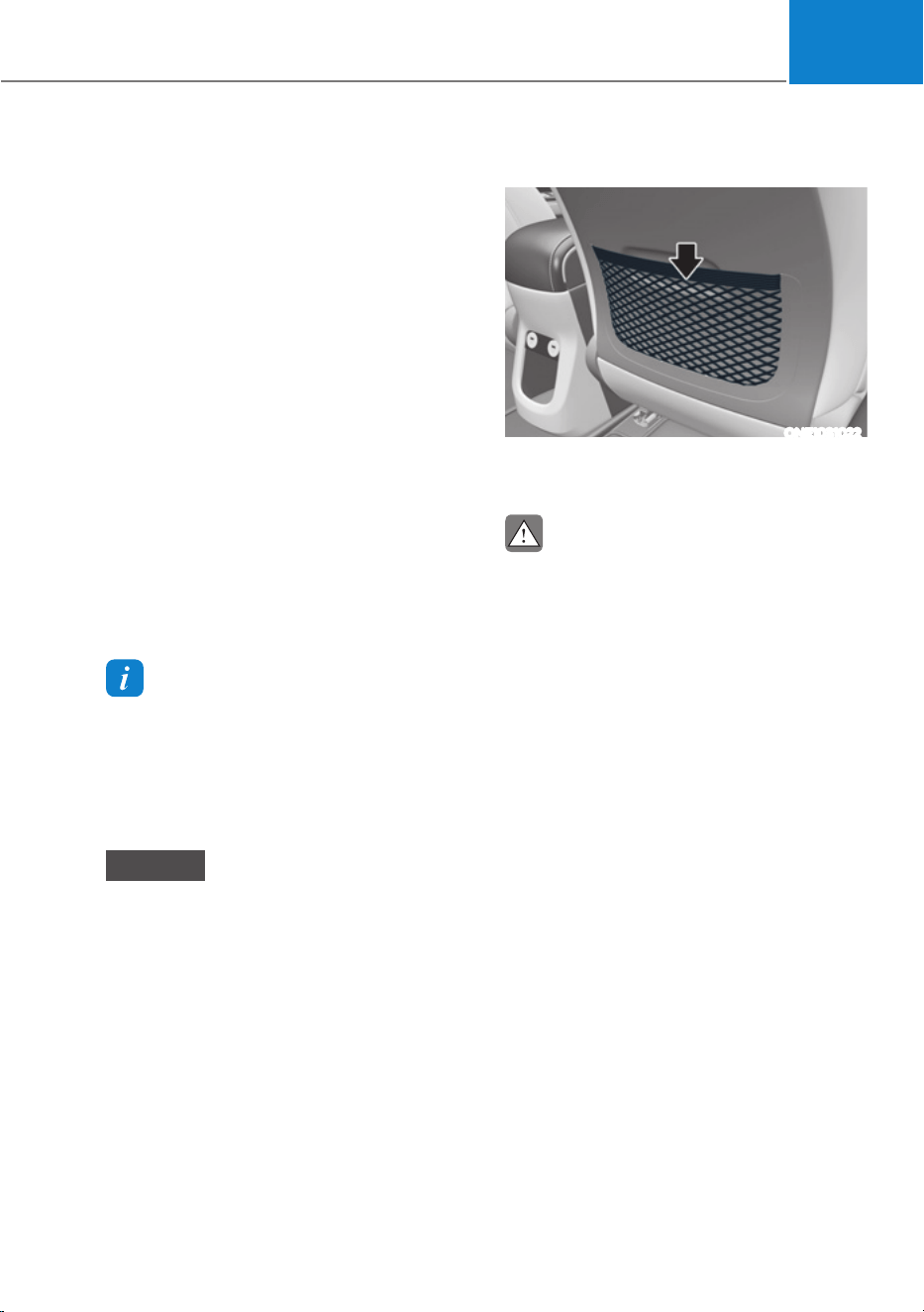
03
3-15
ś To deactivate relaxation comfort seat
If you press the front portion of the
switch (2) while the seat is in the
relaxion comfort seat position, the
seat return backs to the original
position.
When relaxation comfort seat is
deactivated:
ś The driver seat will return to the
position which the gear was in P
(Park).
ś Passenger seat will return to the
original position.
In the following cases, the relaxation
comfort seat will not return to the
original position for the driver’ seat.
ś When the gear is not in P (Parking).
ś When the vehicle is moving more than
1.8 mph (3 km/h).
Information
When relaxation comfort seat cannot be
operated, try to reset Integrated Memory
System. If relaxation comfort seat does
not operate even after Integrated Memory
System is reset, contact an authorized
HYUNDAI dealer.
NOTICE
Do not use the seat switches
simultaneously. It may damage the seat
system.
Seatback pocket
ONE1031022
The seatback pocket is provided on the
back of the front seatbacks.
CAUTION
Do not put heavy or sharp objects in the
seatback pockets. In an accident they
could come loose from the pocket and
injure occupants.
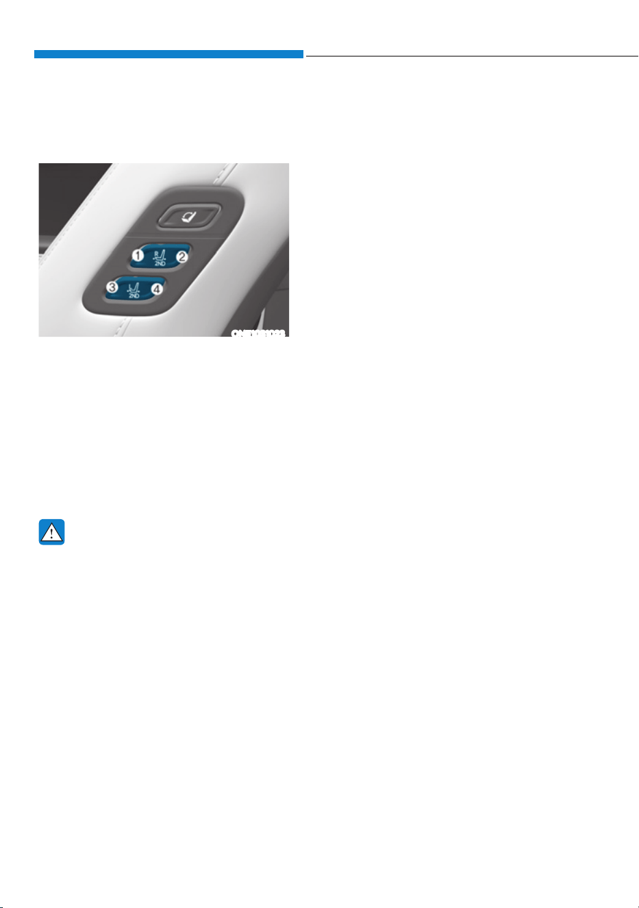
Seats & Safety System
3-16
Rear Seats
Rear seat control switch (if
equipped)
ONE1031023
The front and rear seat passengers may
use the switches to control the rear
seats.
ś Sliding forward or rearward:
Press the switch (1) or (2) to move the
second row right side seat forward or
rearward.
Press the switch (3) or (4) to move the
second row left side seat forward or
rearward.
WARNING
Take the following precautions:
ś Adjusting the seats
- NEVER attempt to adjust the seat
while the vehicle is moving. The
seat may suddenly move and may
injure the passenger.
- Make sure that the seat is locked in
place after the adjustment. If not,
the seat might move unexpectedly
resulting in an accident.
ś Folding the seats
- Do not fold the seatback when
the seat is occupied (for example,
passenger, pets or luggage). It
may injure the passenger or pet, or
damage the luggage.
- Never allow passengers to sit on
top of the folded down seatback
while the vehicle is moving. This is
not a proper seating position and
no seat belts are available for use.
This could result in serious injury
or death in case of an accident or
sudden stop.
- Objects carried on the folded
down seatback should not extend
higher than the top of the front
seatbacks. This could allow cargo
to slide forward and cause injury or
damage during sudden stops.
- When returning the rear seatback
from a folded to an upright
position, hold the seatback and
return it slowly. Ensure that the
seatback is completely locked into
its upright position by pushing
on the top of the seatback. In
an accident or sudden stop, the
unlocked seatback could allow
cargo to move forward with great
force and enter the passenger
compartment, which could result
in serious injury or death.
- When folding the seatback,
slightly pushing the seatback or
head restraint against the folding
direction to control the folding
speed. Without the push, the
seatback may abruptly fold down
and cause injuries when the lever
is pulled.
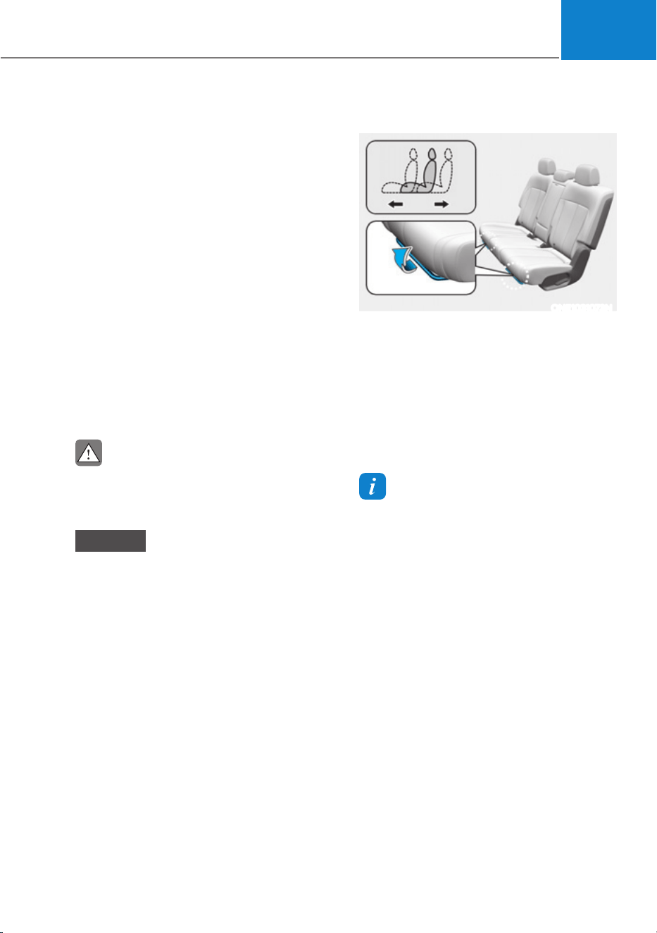
03
3-17
ś Loading cargo
- Make sure the vehicle is off, the
gear shifted to P (Park), and the
parking brake is securely applied
whenever loading or unloading
cargo. Failure to take these steps
may allow the vehicle to move
if the shift button or shift dial is
inadvertently pressed or rotated to
another position.
- When cargo is loaded through
the rear passenger seats, ensure
the cargo is properly secured
to prevent it from moving while
driving.
ś Do not place objects in the rear
seats, since they cannot be properly
secured and may hit vehicle
occupants in a collision causing
serious injury or death.
CAUTION
Do not allow your hands or fingers to
get caught in the seat mechanisms
while adjusting the seats.
NOTICE
To prevent damage to the vehicle:
ś Rear seat belts
Before folding the seatback, insert
the seat belt buckle in the holder
between the seatback and cushion.
And insert the seat belt webbing in
the guide to prevent the seat belt
from being damaged.
ś Cargo
Be careful when loading cargo
through the rear passenger seats
to prevent damage to the vehicle
interior.
Manual adjustment
ONE1031073N
Forward and rearward
To move the seat forward or rearward:
1. Pull the seat slide adjustment lever up
and hold it.
2. Slide the seat to the position you
desire.
3. Release the lever and make sure the
seat is locked in place.
Information
For the optimal safety, slide the rear seat
to the rearmost position.
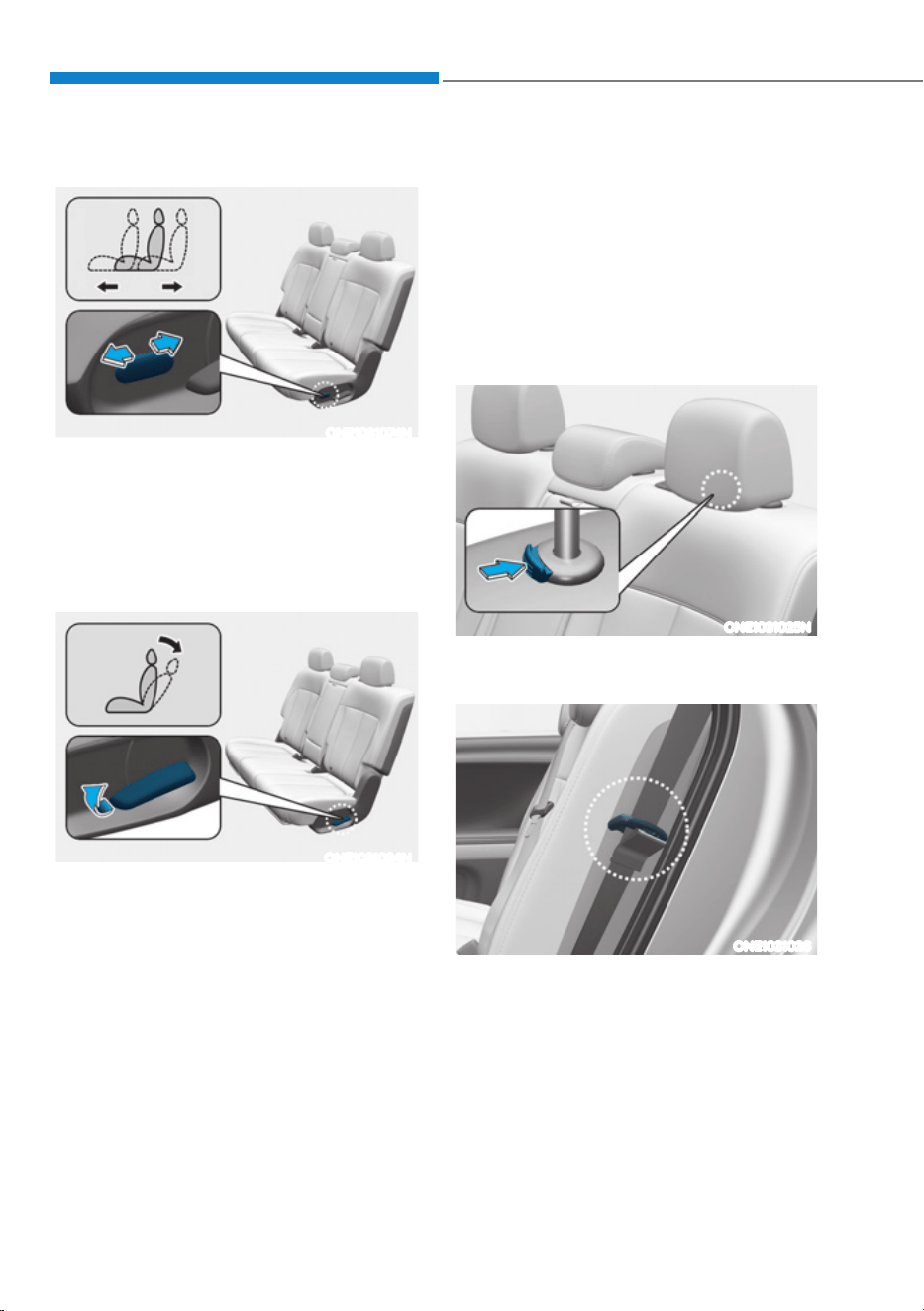
Seats & Safety System
3-18
Power adjustment (if equipped)
ONE1031074N
Forward and rearward
To move the seat forward or rearward:
1. Push the control switch forward or
rearward.
2. Release the switch once the seat
reaches the desired position.
ONE1031024N
Seatback angle
To recline the seatback:
1. Pull up the seatback recline lever.
2. Hold the lever and adjust the seatback
of the seat to the position you desire.
3. Release the lever and make sure the
seatback is locked in place. The lever
MUST return to its original position for
the seatback to lock.
à The seatbacks can be folded with the
seatback recline lever.
Folding the rear seats
The rear seatbacks can be folded to
facilitate carrying long items or to
increase the luggage capacity of the
vehicle.
To fold down the rear seatback:
1. Set the front seatback to the upright
position and if necessary, slide the
front seat forward.
ONE1031025N
2. Lower the rear head restraints to the
lowest position.
ONE1031026
3. Route the seat belt webbing to the
outward of the rear seat to prevent the
belts from being trapped behind or
under the seats.
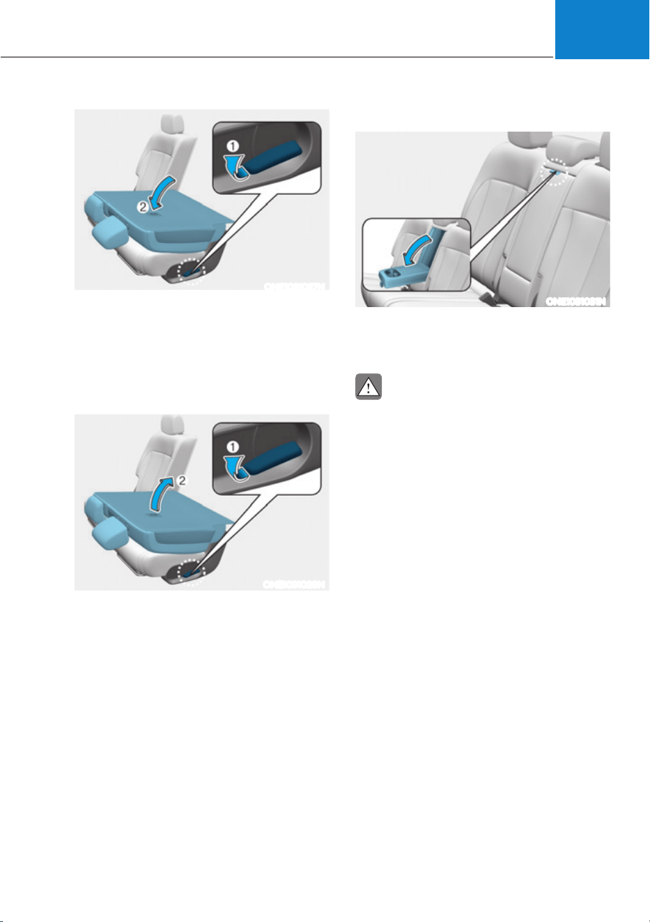
03
3-19
ONE1031027N
4. Pull up the seatback folding lever
(1), then fold the seat (2) toward the
front of the vehicle. When you return
the seatback to its upright position,
always be sure it has locked into
position by pushing on the top of the
seatback.
ONE1031028N
5. To use the rear seat, lift and unfold the
seatback (2) to the upright position
by pulling up the folding lever (1).
Push the seatback firmly until it clicks
into place. Make sure the seatback is
locked in place.
6. Return the rear seat belt to the proper
position.
Armrest
ONE1031031N
The armrest is located in the center of
the rear seat. Pull the armrest down from
the seatback to use it.
CAUTION
The armrest handle may be pressed
when folding the rear seatback, but it
will be restored after a certain period of
time.
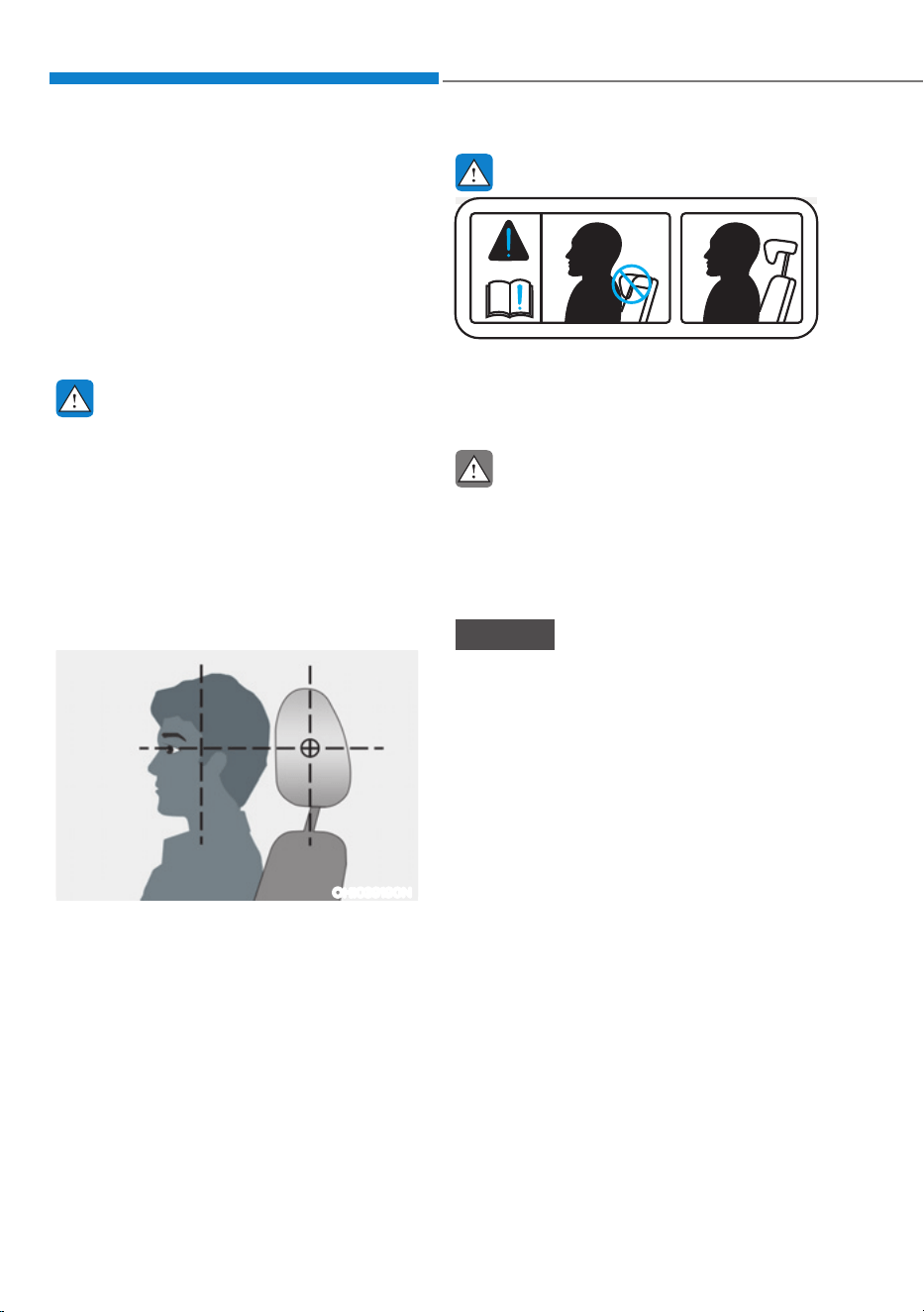
Seats & Safety System
3-20
Head Restraint
The vehicle’s front and rear seats
have adjustable head restraints. The
head restraints provide comfort for
passengers, but more importantly they
are designed to help protect passengers
from whiplash and other neck and spinal
injuries during an accident, especially in
a rear impact collision.
WARNING
To reduce the risk of serious injury or
death in an accident, take the following
precautions when adjusting your head
restraints:
ś Always properly adjust the head
restraints for all passengers BEFORE
starting the vehicle.
ś NEVER let anyone ride in a seat
with the head restraint removed or
reversed.
OHI039190N
ś Adjust the head restraints so the
middle of the head restraint is at the
same height as the height of the top
of the eyes.
ś NEVER adjust the head restraint
position of the driver’s seat when the
vehicle is in motion.
ś Adjust the head restraint as close to
the passenger’s head as possible. Do
not use a seat cushion that holds the
body away from the seatback.
ś Make sure the head restraint locks
into position after adjusting it.
WARNING
OTL035061
When sitting on the rear seat, do not
adjust the height of the head restraint
to the lowest position.
CAUTION
When there is no occupant in the rear
seats, adjust the height of the head
restraint to the lowest position. The
rear seat head restraint can reduce the
visibility of the rear area.
NOTICE
To prevent damage, NEVER hit or pull
on the head restraints.
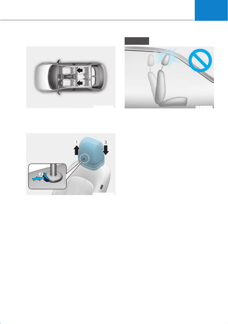
03
3-21
Front seat head restraints
ONE1031076L
The driver’s and front passenger’s seats
are equipped with adjustable head
restraints for the passengers safety and
comfort.
ONE1031016N
Adjusting the height up and down
To raise the head restraint:
1. Pull it up to the desired position (1).
To lower the head restraint:
1. Push and hold the release button (2)
on the head restraint support.
2. Lower the head restraint to the
desired position (3).
NOTICE
OHI038136
If you recline the seatback towards the
front with the head restraint and seat
cushion raised, the head restraint may
come in contact with the sunvisor or
other parts of the vehicle.
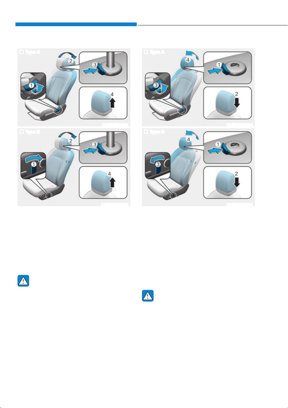
Seats & Safety System
3-22
Type A
ONE1031018N
Type B
ONE1031020N
Removal/Reinstall
To remove the head restraint:
1. Recline the seatback (2) with the
seatback angle switch (1).
2. Pull up the head restraint to the
upmost position and press the
release button (3) to remove the head
restraint (4).
WARNING
NEVER allow anyone to travel in a seat
with the head restraint removed.
Type A
ONE1031019N
Type B
ONE1031021N
To reinstall the head restraint :
1. Recline the seat back by pressing
seatback angle lever or switch (3).
2. Put the head restraint poles (2) into
the holes while pressing the release
button (1).
3. Adjust the head restraint to the
appropriate height.
4. Adjust the seatback angle (4) with the
seatback angle switch (3).
WARNING
Always make sure the head restraint
locks into position after reinstalling and
adjusting it properly.
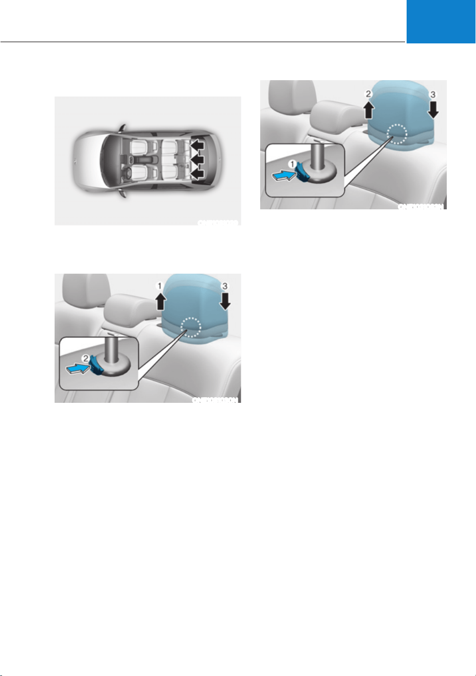
03
3-23
Rear seat head restraints
ONE1031029
The rear seats are equipped with head
restraints in all the seating positions for
the passenger’s safety and comfort.
ONE1031030N
Adjusting the height up and down
To raise the head restraint:
1. Pull it up to the desired position (1).
To lower the head restraint:
1. Push and hold the release button (2)
on the head restraint support.
2. Lower the head restraint to the
desired position (3).
ONE1031083N
Removal/Reinstallation
To remove the head restraint:
1. Raise the head restraint as far as it can
go.
2. Press the head restraint release button
(1) while pulling the head restraint up
(2).
To reinstall the head restraint:
1. Put the head restraint poles into the
holes (3) while pressing the release
button (1).
2. Adjust the head restraint to the
appropriate height.
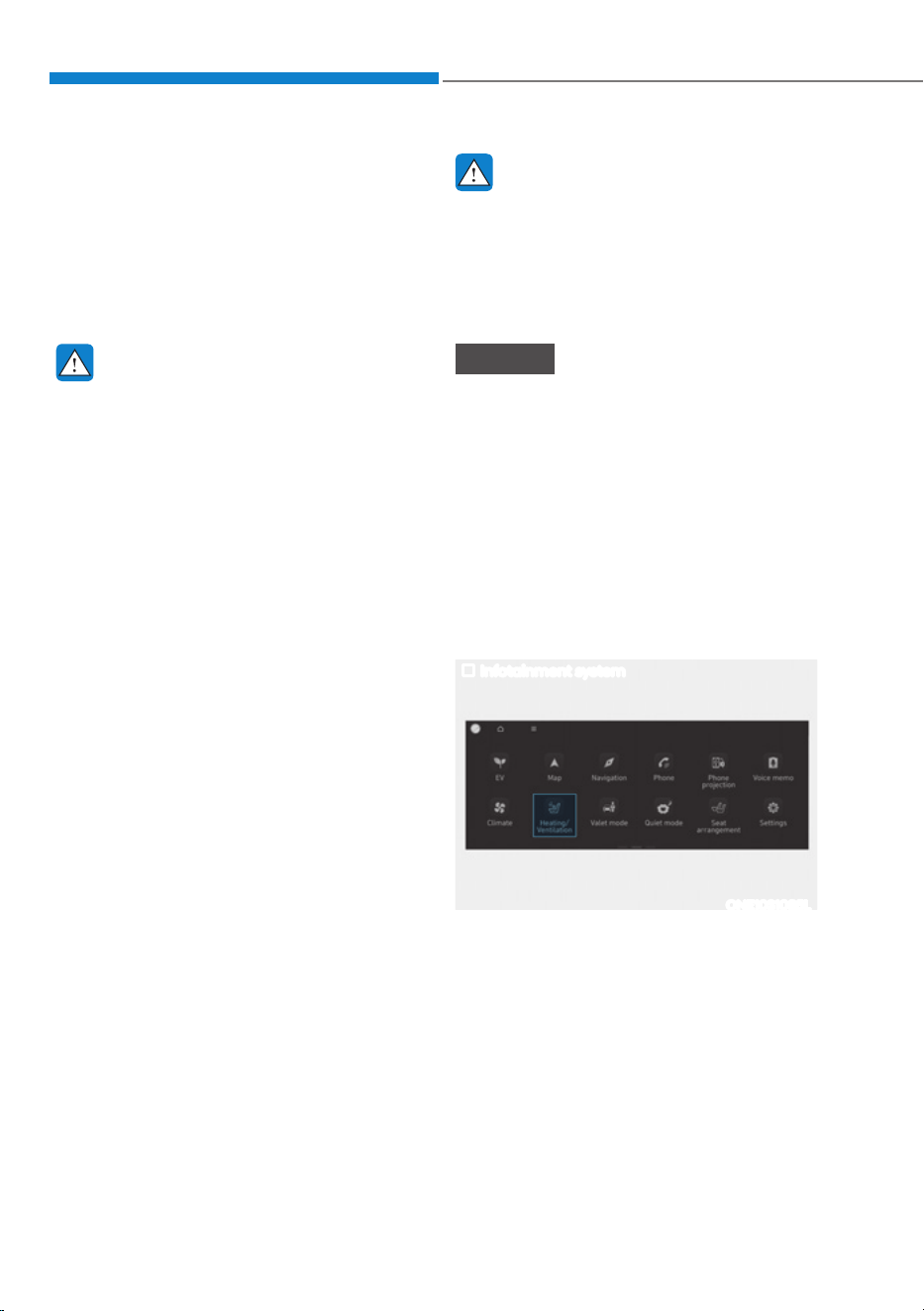
Seats & Safety System
3-24
Seat Warmers
Seat warmers are provided to warm the
seats during cold weather.
During mild weather or under conditions
where the operation of the seat warmer
is not needed, keep the seat warmers
OFF.
WARNING
The seat warmers can cause a SERIOUS
BURN, even at low temperatures and
especially if used for long periods of
time.
Passengers must be able to feel if the
seat is becoming too warm so they can
turn it off, if needed.
Seat warmer consume large amounts
of electricity. Please avoid using seat
warmers while the vehicle is off in order
to prevent battery discharge.
People who cannot detect temperature
change or pain to the skin should
use extreme caution, especially the
following types of passengers:
ś Infants, children, elderly or disabled
persons, or hospital outpatients.
ś People with sensitive skin or who
burn easily.
ś Fatigued individuals.
ś Intoxicated individuals.
ś People taking medication that can
cause drowsiness or sleepiness.
WARNING
NEVER place anything on the seat
that insulates against heat when the
seat warmer is in operation, such as a
blanket or seat cushion. This may cause
the seat warmer to overheat, causing a
burn or damage to the seat.
NOTICE
To prevent damage to the seat warmers
and seats:
ś Never use a solvent such as paint
thinner, benzene, alcohol or gasoline
to clean the seats.
ś Do not place heavy or sharp objects
on seats equipped with seat
warmers.
ś Do not change the seat cover. It may
damage the seat warmer.
Front seat warmers
Infotainment system
ONE1031085L
While the vehicle is running, touch
Heating/Ventilation icon in the
infotainment home screen.
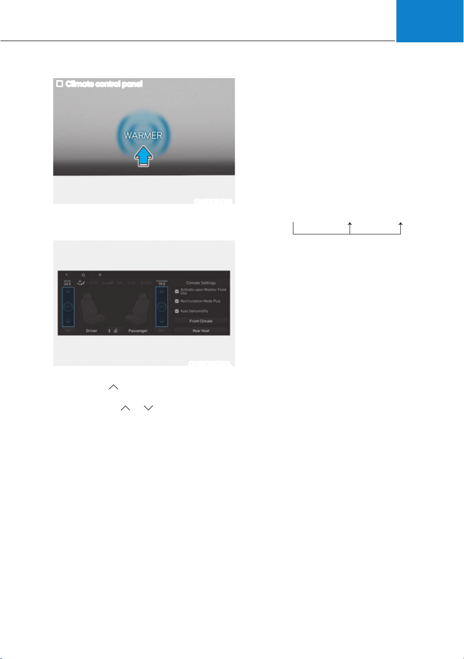
03
3-25
Climate control panel
ONE1031081
Press WARMER in the front climate
control panel.
ONE1031080L
To activate seat warmer of each front
seats, touch
icon on the infotainment
screen. Adjust the temperature by
pressing either
or icons.
The seat warmer will automatically stop
when the seat temperature reaches
certain level and will automatically
reactivate when the seat temperature
drops below certain temperature.
ś Manual temperature control
Refer to the infotainment system
web manual for manual temperature
control.
ś Automatic temperature control
The seat warmer starts to
automatically control the seat
temperature in order to prevent
low temperature burns after being
manually turned on.
2))Ɵ+,*+Ɵ0(',80ƟLOW
PLQ PLQ
You may manually touch the icon to
increase seat temperature. However,
the seat temperature is automatically
adjusted again.
ś Auto. Controls That Use Climate
Control Settings (for driver’s seat)
The seat warmer automatically
controls the seat temperature
depending on the ambient
temperature when the vehicle is
running.
To use this function, it must be
enabled from the Settings menu in the
infotainment system screen. Select:
- 6HWXSƟ9HKLFOH6HWWLQJVƟ6HDWƟ
+HDWHG9HQWLODWHG)HDWXUHVƟ$XWR
Controls That Use Climate Control
6HWWLQJVƟ6HDW:DUPHU9HQWLODWLRQ
ś The seat warmer defaults to the OFF
position whenever the Start/Stop
button is pressed to the ON position.
However, if the Auto. Controls That
Use Climate Control Settings function
is On, the driver’s seat warmer will
turn on and off depending on the
ambient temperature.
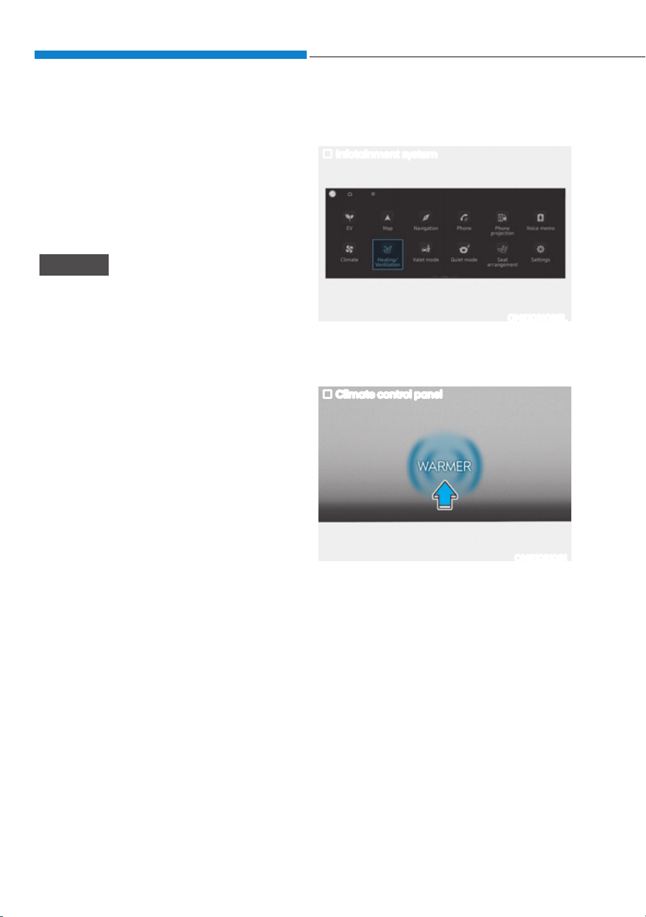
Seats & Safety System
3-26
Air Ventilation Seats
The air ventilation seats are provided
to cool the front seats by blowing air
through small vent holes on the surface
of the seat cushions and seatbacks.
When the operation of the air ventilation
seat is not needed, keep the air
ventilation seats OFF.
NOTICE
To prevent damage to the air ventilation
seats:
ś Never use a solvent such as paint
thinner, benzene, alcohol or gasoline
to clean the seats.
ś Avoid spilling liquids on the surface
of the front seats and seatbacks; this
may cause the air vent holes to block
and not work properly.
ś Do not place materials such as plastic
bags or newspapers under the seats.
They may block the air intake causing
malfunction of the air vent.
ś Do not change the seat covers. It may
damage the air ventilation seat.
ś If the air vents do not operate, restart
the vehicle. If there is no change,
have the vehicle to be inspected by
an authorized HYUNDAI dealer.
Front air ventilation seats
(if equipped)
Infotainment system
ONE1031085L
While the vehicle is running, touch
Heating/Ventilation icon in the
infotainment home screen.
Climate control panel
ONE1031081
Press WARMER in the front climate
control panel.

03
3-27
ONE1031080L
To activate air ventilation of each front
seats, touch
icon on the infotainment
screen. Adjust the airflow by pressing
either
or icons.
ś If the air ventilation seat is positioned
at HIGH, the airflow speed will
increase according to vehicle speed.
ś Use the air ventilation seat with the
air conditioning on for more effective
ventilation.
ś It may take 3~5 minutes after switch
operation to feel the temperature
change.
Refer to the infotainment system
web manual for manual temperature
control.
ś Auto. Controls That Use Climate
Control Settings (for driver’s seat)
The air ventilation seat automatically
controls the seat temperature
depending on the ambient
temperature when the vehicle is
running.
To use this function, it must be
enabled from the Settings menu in the
infotainment system screen. Select:
- 6HWXSƟ9HKLFOH6HWWLQJVƟ6HDWƟ
+HDWHG9HQWLODWHG)HDWXUHVƟ$XWR
Controls That Use Climate Control
6HWWLQJVƟ6HDW:DUPHU9HQWLODWLRQ
ś The air ventilation seats defaults to the
OFF position whenever the Start/Stop
button is pressed to the ON position.
However, if the Auto. Controls That
Use Climate Control Settings function
is on, the driver’s seat warmer will turn
on and off depending on the ambient
temperature.

Seats & Safety System
3-28
Advanced Rear Occupant Alert
(ROA) (if equipped)
Advanced Rear Occupant Alert is
provided to help prevent a driver from
leaving a vehicle with the rear passenger
left in the vehicle.
System setting
To use Rear Occupant Alert, it must be
enabled from the Settings menu in the
infotainment system screen. Select:
- 6HWXSƟ9HKLFOH6HWWLQJVƟ
&RQYHQLHQFHƟ5HDU2FFXSDQW$OHUW
(ROA)
For detailed information, refer to the
separately supplied infotainment
system manual.
System operation
ś First alert
When you turn off the vehicle and
open the driver’s door after opening
and closing the rear door or liftgate,
the ‘Check rear seats’ warning
message appears on the cluster.
WARNING
Even if your vehicle is equipped with
Advanced Rear Occupant Alert (ROA),
always make sure to check the rear seat
before you leave the vehicle.
Advanced Rear Occupant Alert (ROA)
may not operate when:
ś Movement does not continue for
a certain period of time or the
movement is small.
ś A child is not seated in a child
restraint system.
ś Movement is detected in areas other
than the rear seats.
ś The rear passenger is covered with a
fabric containing metallic substance
such as a blanket.
ś An object in the vehicle blocks the
sensor.
ś The sensor is contaminated by
foreign material.
ś An animal at the rear seat or luggage
compartment is not large enough to
be detected by the sensor or there is
hardly any movement.
ś Attaching objects or modifying the
interior ceiling, or the interior ceiling
is deformed or damaged.
ś There are electronic interference
around the vehicle.
ś Other environmental reasons that
may affect the system.

03
3-29
SEAT BELTS
This section describes how to use the
seat belts properly. It also describes
some of the things not to do when using
seat belts.
Seat Belt Safety Precautions
Always fasten your seat belt and make
sure all passengers have fastened their
seat belts before starting any trip. Air
bags are designed to supplement the
seat belt as an additional safety device,
not a replacement. Most states require all
occupants of a vehicle to wear seat belts.
WARNING
Seat belts must be used by ALL
passengers whenever the vehicle is
moving. Take the following precautions
when adjusting and wearing seat belts:
ś Children under the age of 13 should
be properly restrained in the rear
seats.
ś Never allow children to ride in the
front passenger seat, unless the air
bag is deactivated. If a child is seated
in the front passenger seat, move the
seat as far back as possible. And the
child must always be restrained in
the seat properly.
ś NEVER allow an infant or child to be
carried on an occupant’s lap.
ś NEVER ride with the seatback
reclined when the vehicle is moving.
ś Do not allow children to share a seat
or seat belt.
ś Do not wear the shoulder belt under
your arm or behind your back.
ś NEVER wear a seat belt over fragile
objects. If there is a sudden stop or
impact, the seat belt can damage it.
ś Do not use the seat belt if it is
twisted. A twisted seat belt will not
protect you properly in an accident.
ś Do not use a seat belt if the webbing
or hardware is damaged.
ś Do not latch the seat belt into the
buckles of other seats.
ś NEVER unfasten the seat belt
while driving. This may cause loss
of vehicle control resulting in an
accident.
ś Make sure there is nothing in the
buckle interfering with the seat
belt latch mechanism, because any
materials in the buckle can cause the
seat belt not to be fastened securely.
ś No modifications or additions
should be made by the user which
will either prohibit the seat belt
adjusting devices from operating to
remove slack, or prohibit the seat
belt assembly from being adjusted to
remove slack.
WARNING
Damaged seat belts and seat belt
assemblies will not operate properly.
Always replace:
ś Frayed, contaminated, or damaged
webbing.
ś Damaged hardware.
ś The entire seat belt assembly after it
has been worn in an accident, even
if damage to webbing or assembly is
not apparent.
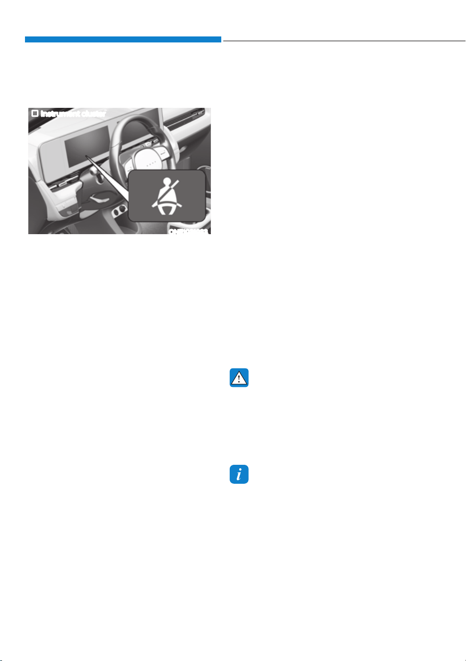
Seats & Safety System
3-30
Seat Belt Warning Light
Driver’s seat belt warning
Instrument cluster
ONE1031033
As a reminder to the driver, the driver’s
seat belt warning lights will illuminate
for approximately 6 seconds each time
the START/STOP button is in the ON
position regardless of belt fastening. If
the seatbelt is not fastened, the warning
chime will sound for about 6 seconds.
If you start to drive without the seat belt
fastened or you unfasten the seat belt
when you drive under 12 mph (20 km/h)
or stop, the corresponding warning light
will illuminate.
If you start to drive without the seat
belt fastened or you unfasten the seat
belt when you drive 12 mph (20 km/h)
and faster, the warning light will blink
and warning chime will sound for
approximately 100 seconds.
When the seat belt is unfastened during
driving, the warning light will illuminate
when the speed is under 12 mph (20
km/h).
When the speed is 12 mph (20 km/h)
and faster, the warning light will blink
and warning chime will sound for
approximately 100 seconds.
Front passenger’s seat belt warning
As a reminder to the front passenger,
the front passenger’s seat belt warning
lights will illuminate for approximately
6 seconds each time the START/STOP
button is in the ON position regardless of
belt fastening.
If you start to drive without the seat belt
fastened or you unfasten the seat belt
when you drive under 12 mph (20 km/h)
or stop, the corresponding warning light
will illuminate.
If you start to drive without the seat
belt fastened or you unfasten the seat
belt when you drive 12 mph (20 km/h)
and faster, the warning light will blink
and warning chime will sound for
approximately 100 seconds.
When the seat belt is unfastened during
driving, the warning light will illuminate
when the speed is under 12 mph (20
km/h). When the speed is 12 mph (20
km/h) and faster, the warning light will
blink and warning chime will sound for
approximately 100 seconds.
WARNING
Riding in an improper position
adversely affects the front passenger’s
seat belt warning system. It is important
for the driver to instruct the passenger
to properly be seated as instructed in
this manual.
Information
ś Although the front passenger seat is not
occupied, the seat belt warning light
will blink or illuminate for 6 seconds.
ś The front passenger’s seat belt warning
may operate when luggage is placed on
the front passenger seat.
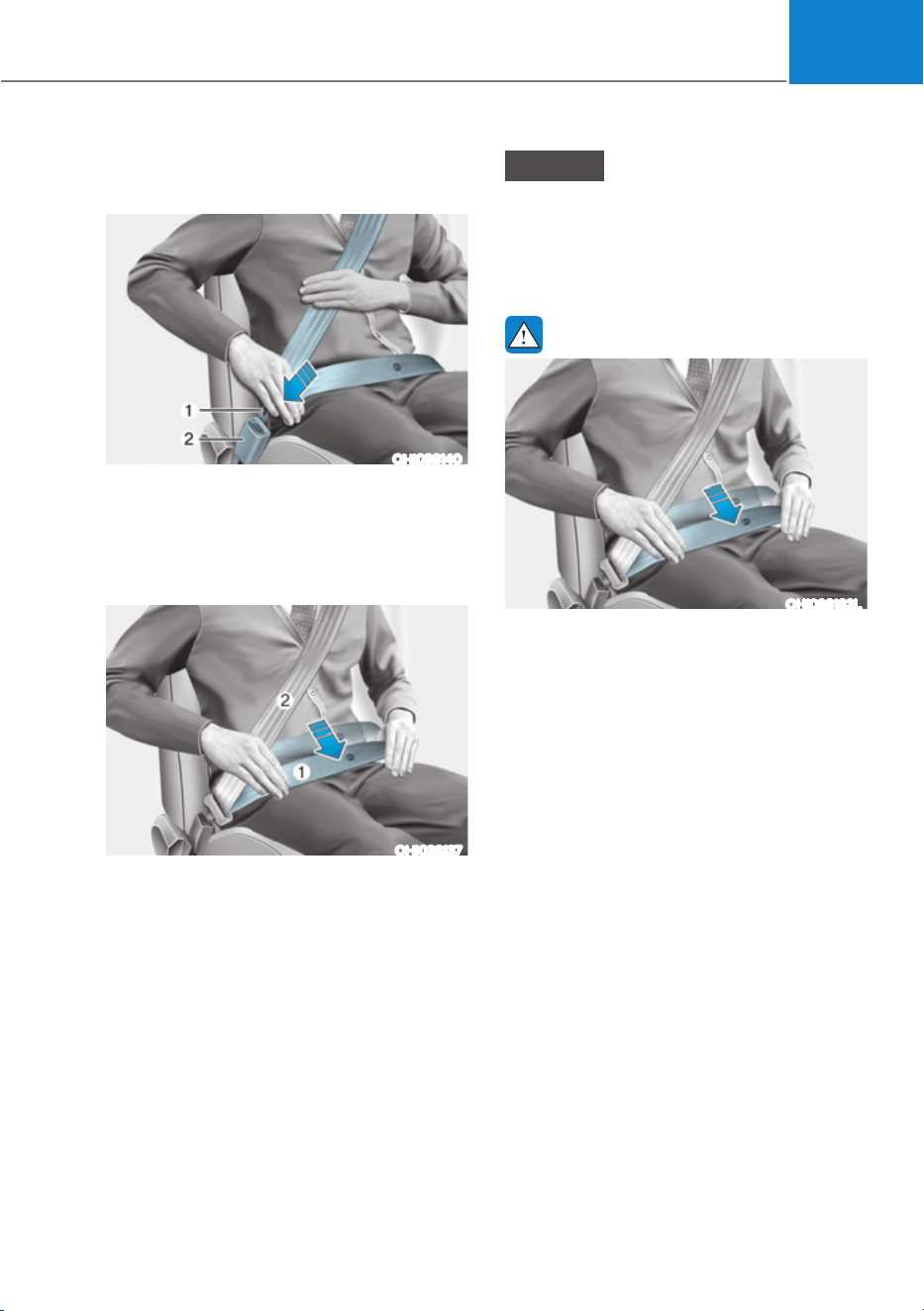
03
3-31
Seat Belt Restraint System
Lap/shoulder belt
OHI038140
To fasten your seat belt:
Pull it out of the retractor and insert the
metal tab (1) into the buckle (2). There
will be an audible “click” when the tab
locks into the buckle.
OHI038137
You should place the lap belt (1) portion
across your hips and the shoulder belt (2)
portion across your chest.
The seat belt automatically adjusts to the
proper length after the lap belt portion
is adjusted manually so that it fits snugly
around your hips. If you lean forward in
a slow, easy motion, the belt will extend
and move with you.
If there is a sudden stop or impact, the
belt will lock into position. It will also lock
if you try to lean forward too quickly.
NOTICE
If you are not able to smoothly pull
enough of the seat belt out from the
retractor, firmly pull the seat belt out
and release it. After release, you will be
able to pull the belt out smoothly.
WARNING
OHI038182L
Improperly positioned seat belts may
increase the risk of serious injury
in an accident. Take the following
precautions when adjusting the seat
belt:
ś Position the lap portion of the seat
belt as low as possible across your
hips, not on your waist, so that it
fits snugly. This allows your strong
pelvic bones to absorb the force of
the crash, reducing the chance of
internal injuries.
ś Position one arm under the shoulder
belt and the other over the belt, as
shown in the illustration.
ś Always position the shoulder belt
anchor into the locked position at the
appropriate height.
ś Never position the shoulder belt
across your neck or face.
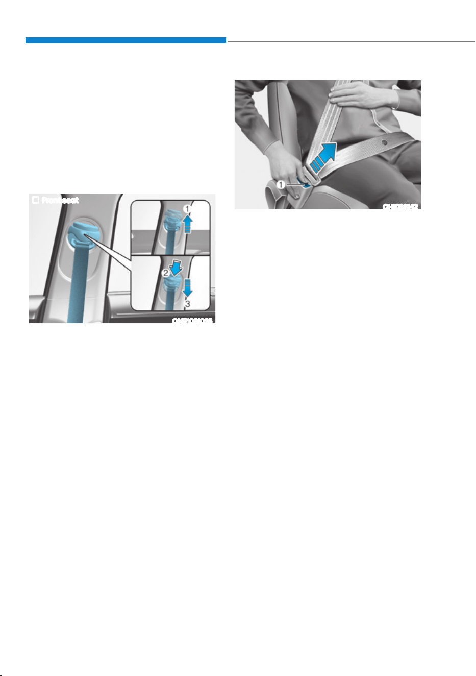
Seats & Safety System
3-32
Height adjustment
You can adjust the height of the shoulder
belt anchor to one of the four different
positions for maximum comfort and
safety.
The shoulder portion should be adjusted
so it lies across your chest and midway
over your shoulder nearest the door, not
over your neck.
Front seat
ONE1031035
To adjust the height of the seat belt
anchor, lower or raise the height adjuster
into an appropriate position.
To raise the height adjuster, pull it up
(1). To lower it, push it down (3) while
pressing the height adjuster button (2).
Release the button to lock the anchor
into position. Try sliding the height
adjuster to make sure that it has locked
into position.
OHI038142
To release your seat belt:
Press the release button (1) in the locking
buckle.
Once released, the belt should
automatically draw back into the
retractor. If this does not happen, check
the belt to be sure it is not twisted, then
try again.
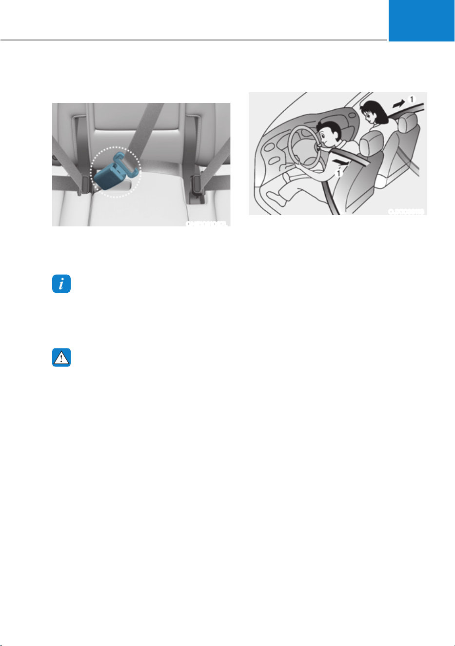
03
3-33
Rear center seatbelt
(3-point rear center seat belt)
ONE1031087L
When using the rear center seat belt, the
buckle with the “CENTER” mark must be
used.
Information
If you are not able to pull out the safety
belt from the retractor, firmly pull the belt
out and release it. After release, you will be
able to pull the belt out smoothly.
WARNING
Make sure that the seatback is locked in
place when using the rear center seat
belt.
If not, the seatback may move when
there is a sudden stop or collision,
which could result in serious injury.
Pre-tensioner seat belt
OJX1039118
Your vehicle is equipped with driver’s
and front passenger’s Pre-tensioner
Seat Belts(Retractor Pretensioner). The
purpose of the pre-tensioner is to make
sure the seat belts fit tightly against the
occupant’s body in certain frontal or side
collision(s). The Retractor Pre-tensioner
may be activated in certain crashes
where the frontal collision(s) is severe
enough.
When the vehicle stops suddenly, or
if the occupant tries to lean forward
too quickly, the seat belt retractor will
lock into position. In certain frontal or
side collision(s), the pre-tensioner will
activate and pull the seat belt into tighter
contact against the occupant’s body.

Seats & Safety System
3-34
(1) Retractor Pretensioner
The purpose of the retractor pre-
tensioner is to make sure that the
shoulder belts fit in tightly against the
occupant’s upper body in certain frontal
or side collision(s).
If the system senses excessive tension
on the driver or passenger’s seat belt
when the pre-tensioner system activates,
the load limiter inside the retractor
pre-tensioner will release some of the
pressure on the affected seat belt.
WARNING
ś Always wear your seat belt and sit
properly in your seat.
ś Do not use the seat belt if it is loose
or twisted. A loose or twisted seat
belt will not protect you properly in
an accident.
ś Do not place anything near the
buckle. This may adversely affect
the buckle and cause it to function
improperly.
ś Always replace your pre-tensioners
after activation or an accident.
ś NEVER inspect, service, repair or
replace the pre-tensioners yourself.
Have the pre-tensioners inspected,
serviced, repaired or replaced by an
authorized HYUNDAI dealer.
ś Do not hit the seat belt assemblies.
WARNING
Do not touch the pre-tensioner seat
belt assemblies for several minutes
after they have been activated. When
the pre-tensioner seat belt mechanism
deploys during a collision, the pre-
tensioner can become hot and can burn
you.
CAUTION
Body work on the front area of the
vehicle may damage the pre-tensioner
seat belt system. Therefore, have the
system serviced by an authorized
HYUNDAI dealer.
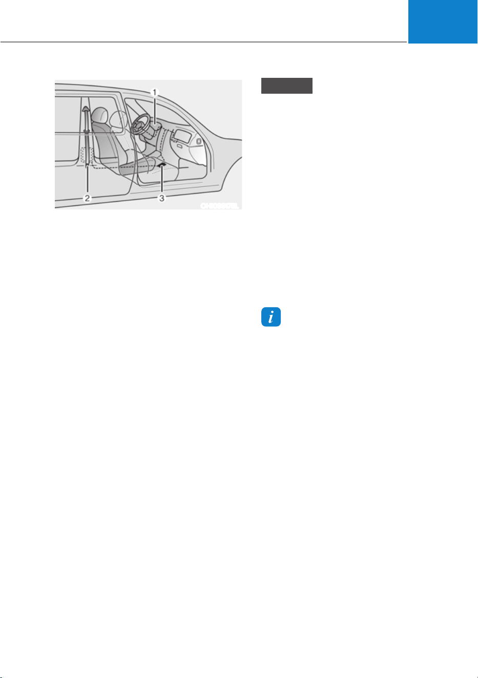
03
3-35
OHI038175L
The Pre-Tensioner Seat Belt System
consists mainly of the following
components. Their locations are shown
in the illustration above:
(1) SRS air bag warning light
(2) Retractor pre-tensioner
(3) SRS control module
NOTICE
The sensor that activates the SRS
control module is connected with the
pre–tensioner seat belts. The SRS air
bag warning light on the instrument
cluster will illuminate for approximately
3~6 seconds after the Start/Stop button
is in the ON position, and then it should
turn off.
If the pre-tensioner is not working
properly, the warning light will
illuminate even if the SRS air bag is not
malfunctioning. If the warning light
does not illuminate, stays illuminated
or illuminates when the vehicle is being
driven, have the pre-tensioner seat
belts and/or SRS control module be
inspected by an authorized HYUNDAI
dealer as soon as possible.
Information
ś Pre-tensioner seat belts may be
activated in certain frontal or side
collisions or rollover situations (if
equipped with rollover sensor).
ś When the pre-tensioner seat belts are
activated, a loud noise may be heard
and fine dust, which may appear to be
smoke, may be visible in the passenger
compartment. These are normal
operating conditions and are not
hazardous.
ś Although it is non-toxic, the fine dust
may cause skin irritation and should
not be inhaled for prolonged periods.
Wash all exposed skin areas thoroughly
after an accident in which the pre-
tensioner seat belts were activated.

Seats & Safety System
3-36
Additional Seat Belt Safety
Precautions
Seat belt use during pregnancy
The seat belt should always be used
during pregnancy. The best way to
protect your unborn child is to protect
yourself by always wearing the seat belt.
Pregnant women should always wear
a lap-shoulder seat belt. Place the
shoulder belt across your chest, routed
between your breasts and away from
your neck. Place the lap belt below your
belly so that it fits SNUGLY across your
hips and pelvic bone, under the rounded
part of the belly.
WARNING
To reduce the risk of serious injury or
death to an unborn child during an
accident, pregnant women should
NEVER place the lap portion of the
seat belt above or over the area of the
abdomen where the unborn child is
located.
Seat belt use and children
Infant and small children
Most countries have Child Restraint
System laws which require children to
travel in approved Child Restraint System
devices, including booster seats. The age
at which seat belts can be used instead
of Child Restraint System differs among
countries, so you should be aware of the
specific requirements in your country,
and where you are travelling. Infant and
Child Restraint System must be properly
placed and installed in a rear seat.
For more information refer to the “Child
Restraint Systems” section in this
chapter.
WARNING
ALWAYS properly restrain infants and
small children in a Child Restraint
System appropriate for the child’s
height and weight.
To reduce the risk of serious injury or
death to a child and other passengers,
NEVER hold a child in your lap or arms
when the vehicle is moving. The violent
forces created during an accident will
tear the child from your arms and throw
the child against the interior of the
vehicle.
Small children are best protected
from injury in an accident when
properly restrained in the rear seat
by a child restraint system that meets
the requirements of the Federal Motor
Vehicle Safety Standards. Before buying
any child restraint system, make sure
that it has a label certifying that it meets
Federal Motor Vehicle Safety Standard
FMVSS 213. The restraint must be
appropriate for your child’s height and
weight. Check the label on the child
restraint for this information. Refer to the
“Child Restraint Systems” section in this
chapter.

03
3-37
Larger children
Children under age 13 and who are
too large for a booster seat should
always occupy the rear seat and use the
available lap/shoulder belts. A seat belt
should lie across the upper thighs and
be snug across the shoulder and chest
to restrain the child safely. Check belt fit
periodically. A child’s squirming could
put the belt out of position. In the event
of an accident, children are afforded the
best safety restrained by a proper Child
Restraint System in the rear seats.
If a larger child over age 13 must be
seated in the front seat, the child must
be securely restrained by the available
lap/shoulder belt and the seat should be
placed in the rearmost position.
If the shoulder belt portion slightly
touches the child’s neck or face, try
placing the child closer to the center
of the vehicle. If the shoulder belt still
touches their face or neck, they need to
be returned to an appropriate booster
seat in the rear seat.
WARNING
ś Always make sure larger children’s
seat belts are worn and properly
adjusted.
ś NEVER allow the shoulder belt to
contact the child’s neck or face.
ś Do not allow more than one child to
use a single seat belt.
Seat belt use and injured people
A seat belt should be used when an
injured person is being transported.
Consult a physician for specific
recommendations.
One person per belt
Two people (including children) should
never attempt to use a single seat belt.
This could increase the severity of
injuries in case of an accident.
Do not lie down
Sitting in a reclined position when the
vehicle is in motion can be dangerous.
Even when buckled up, the protections
of your restraint system (seat belts
and/or air bags) is greatly reduced by
reclining your seatback.
Seat belts must be snug against your
hips and chest to work properly.
During an accident, you could be thrown
into the seat belt, causing neck or other
injuries.
The more the seat back is reclined, the
greater the chance for the passenger’s
hips to slide under the lap belt or the
passenger’s neck to strike the shoulder
belt.
WARNING
ś NEVER ride with a reclined seatback
when the vehicle is moving.
ś Riding with a reclined seatback
increases your chance of serious
or fatal injuries in the event of a
collision or sudden stop.
ś Driver and passengers should always
sit well back in their seats with the
seatbacks upright and should be
belted properly.

Seats & Safety System
3-38
Care of Seat Belts
Seat belt systems should never be
disassembled or modified. In addition,
care should be taken to assure that seat
belts and belt hardware are not damaged
by seat hinges, doors or other abuse.
Periodic inspection
All seat belts should be inspected
periodically for wear or damage of any
kind. Any damaged parts should be
replaced as soon as possible.
Keep belts clean and dry
Seat belts should be kept clean and
dry. If belts become dirty, they can be
cleaned by using a mild soap solution
and warm water. Bleach, dye, strong
detergents or abrasives should not be
used because they may damage and
weaken the fabric.
When to replace seat belts
The entire seat belt assembly or
assemblies should be replaced if the
vehicle has been involved in an accident.
This should be done even if no damage is
visible. Consult an authorized HYUNDAI
dealer.

03
3-39
&+,/'5(675$,176<67(0ǣ&56Ǥ
Children Always in the Rear
WARNING
Always properly restrain children in
the rear seats of the vehicle. Children
of all ages are safer when restrained
in the rear seat. A child riding in the
front passenger seat can be forcefully
struck by an inflating air bag resulting in
SERIOUS INJURY or DEATH.
Children under age 13 should always
ride in the rear seats and must always be
properly restrained to minimize the risk
of injury in an accident, sudden stop or
sudden maneuver.
According to accident statistics, children
are safer when properly restrained in the
rear seats than in the front seat. Even
with air bags, children can be seriously
injured or killed. Children too large for a
Child Restraint System must use the seat
belts provided.
All 50 states have child restraint laws
which require children to travel in
approved Child Restraint Systems.
The laws governing the age or height/
weight restrictions at which seat belts
can be used instead of Child Restraint
System differs among states, so
you should be aware of the specific
requirements in your country, and where
you are travelling.
Child Restraint Systems must be properly
placed and installed in the rear seat.
You must use a commercially available
Child Restraint System that meets the
requirements of the Federal Motor
Vehicle Safety Standards (FMVSS 213).
Child Restraint Systems are generally
designed to be secured in a vehicle seat
by lap belt portion of a lap/shoulder belt,
or by a LATCH system in the rear seats of
the vehicle.
Child Restraint System (CRS)
Infants and younger children must be
restrained in an appropriate rearward-
facing or forward-facing CRS that has
first been properly secured to the seat
of the vehicle. Read and comply with
the instructions for installation and use
provided by the manufacturer of the
Child Restraint System.
WARNING
An improperly secured child restraint
can increase the risk of SERIOUS
INJURY or DEATH in an accident. Always
take the following precautions when
using a Child Restraint System:
ś NEVER install a child or infant
restraint in the front passenger's
seat.
ś Always properly secure the child
restraint to a rear seat of the vehicle.
ś Always follow the child restraint
system manufacturer's instructions
for installation and use.
ś Always properly restrain your child in
the child restraint.
ś If the vehicle head restraint prevents
proper installation of a child seat
(as described in the child restraint
system manual), the head restraint of
the respective seating position shall
be readjusted or entirely removed.
ś Do not use an infant carrier or a
child safety seat that "hooks" over
a seatback, it may not provide
adequate protection in an accident.
ś After an accident, have an authorized
HYUNDAI dealer check the child
restraint system, seat belts, tether
anchors and lower anchors.

Seats & Safety System
3-40
Selecting a Child Restraint
System (CRS)
When selecting a Child Restraint System
for your child, always:
ś Make sure the Child Restraint System
has a label certifying that it meets
applicable Federal Motor Vehicle
Safety Standards (FMVSS 213).
ś Select a Child Restraint System based
on your child’s height and weight. The
required label or the instructions for
use typically provide this information.
ś Select a Child Restraint System that
fits the vehicle seating position where
it will be used.
ś Read and comply with the warnings
and instructions for installation and
use provided with the Child Restraint
System.
Child Restraint System types
There are three main types of Child
Restraint Systems: rearward-facing,
forward-facing and booster Child
Restraint Systems.
They are classified according to the
child’s age, height and weight.
ONE1031037N
Rearward-facing Child Restraint System
A rearward-facing Child Restraint System
provides restraint with the seating
surface against the back of the child. The
harness system holds the child in place,
and in an accident, acts to keep the child
positioned in the Child Restraint Systems
and reduce the stress to the fragile neck
and spinal cord.
All children under the age of one year
must always ride in a rearward-facing
Child Restraint System. Convertible and
3-in-1 Child Restraint Systems typically
have higher height and weight limits for
the rearward-facing position, allowing
you to keep your child rearward-facing
for a longer period of time.
Keep using Child Restraint Systems in
the rearward-facing position as long as
children fit within the height and weight
limits allowed by the Child Restraint
System’s manufacturer. It’s the best way
to keep them safe.
Once your child has outgrown the
rearward-facing Child Restraint System,
your child is ready for a forward-facing
Child Restraint System with a harness.
WARNING
NEVER install a child or infant restraint
in the front passenger's seat.
Placing a rearward-facing child restraint
in the front seat can result in SERIOUS
INJURY or DEATH if the child restraint is
struck by an inflating air bag.
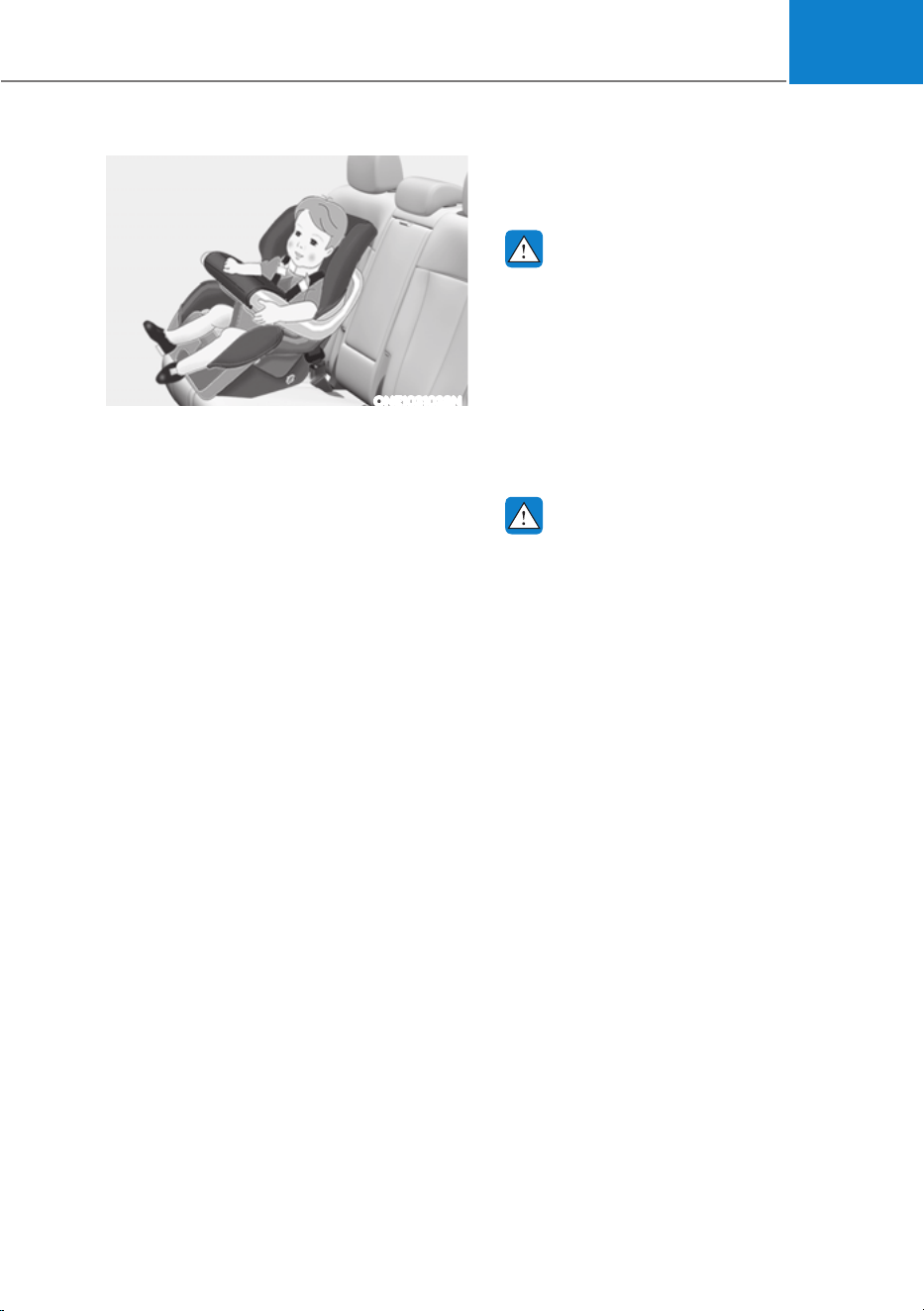
03
3-41
ONE1031038N
Forward-facing Child Restraint System
A forward-facing Child Restraint System
provides restraint for the child’s body
with a harness. Keep children in a
forward-facing Child Restraint System
with a harness until they reach the top
height or weight limit allowed by your
Child Restraint System’s manufacturer.
Once your child outgrows the forward-
facing Child Restraint System, your child
is ready for a booster seat.
Booster seats
A booster seat is a Child Restraint
System designed to improve the fit of
the vehicle’s seat belt system. A booster
seat positions the seat belt so that it
fits properly over the stronger parts of
your child’s body. Keep your children in
booster seats until they are big enough
to fit in a seat belt properly.
For a seat belt to fit properly, the lap belt
must lie comfortable across the upper
thighs, not the stomach. The shoulder
belt should lie comfortable across the
shoulder and chest and not across the
neck or face. Children under age 13
must always be properly restrained to
minimize the risk of injury in an accident,
sudden stop or sudden maneuver.
Installing a Child Restraint
System (CRS)
WARNING
Before installing your Child Restraint
System always:
Read and follow the instructions
provided by the manufacturer of the
Child Restraint System.
Failure to follow all warnings and
instructions could increase the risk of
the SERIOUS INJURY or DEATH if an
accident occurs.
WARNING
If the vehicle head restraint prevents
proper installation of a Child Restraint
System, the head restraint of the
respective seating position shall be
readjusted or entirely removed.
After selecting a proper Child Restraint
System for your child and checking that
the Child Restraint System fits properly
on the seating position, there are three
general steps for a proper installation:
ś Properly secure the Child Restraint
System to the vehicle. All Child
Restraint Systems must be secured
to the vehicle with the lap belt or lap
part of a lap/shoulder belt or with the
lower anchor and/or tether anchor
and/or with the support leg.

Seats & Safety System
3-42
ś Make sure the Child Restraint System
is firmly secured. After installing a
Child Restraint System to the vehicle,
push and pull the seat forward and
from side-to-side to verify that it is
securely attached to the seat. A Child
Restraint System secured with a seat
belt should be installed as firmly as
possible. However, some side-to-side
movement can be expected.
When installing a Child Restraint
System, adjust the vehicle seat and
seatback (up and down, forward
and rearward) so that your child fits
in the Child Restraint System in a
comfortable manner.
ś Secure the child in the Child
Restraint System. Make sure the
child is properly strapped in the Child
Restraint System according to the
Child Restraint System manufacturer’s
instructions.
CAUTION
A Child Restraint System in a closed
vehicle can become very hot. To prevent
burns, check the seating surface and
buckles before placing your child in the
Child Restraint System.
Lower Anchors and Tether for
Children (LATCH System)
The LATCH system holds a Child
Restraint System during driving and in
an accident. This system is designed
to make installation of the Child
Restraint System easier and reduce
the possibility of improperly installing
your Child Restraint System. The LATCH
system uses anchors in the vehicle and
attachments on the Child Restraint
System. The LATCH system eliminates
the need to use seat belts to secure the
Child Restraint System to the rear seats.
Lower anchors are metal bars built into
the vehicle. There are two lower anchors
for each LATCH seating position that will
accommodate a Child Restraint System
with lower attachments.
To use the LATCH system in your vehicle,
you must have a Child Restraint System
with LATCH attachments.
The Child Restraint System manufacturer
will provide you with instructions on how
to use the Child Restraint System with its
attachments for the LATCH anchorages.
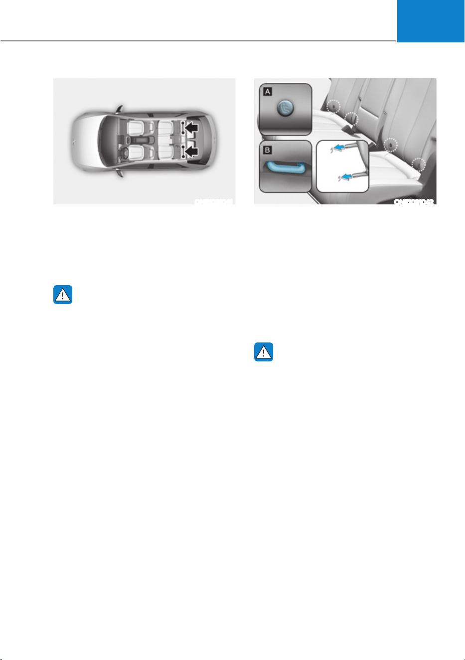
03
3-43
ONE1031041
LATCH anchors have been provided in
the left and right outboard rear seating
positions. Their locations are shown
in the illustration. There are no LATCH
anchors provided for the center rear
seating position.
WARNING
Do not attempt to install a Child
Restraint System using LATCH anchors
in the rear center seating position.
There are no LATCH anchors provided
for this seat. Using the outboard seat
anchors can damage the anchors which
may break or fail in a collision resulting
in serious injury or death.
ONE1031042
[A] : Lower Anchor Position Indicator
[B] : Lower Anchor
The lower anchor position indicator
symbols are located on the left and right
rear seat backs to identify the position
of the lower anchors in your vehicle (see
arrows in illustration).
The LATCH anchors are located between
the seatback and the seat cushion of the
rear seat left and right outboard seating
positions.
WARNING
Before installing the Child Restraint
System, make sure that there are no
objects (for example, toy, pen, wire)
around the lower anchor area. Those
objects may damage either the seat belt
system or the Child Restraint System
during the installment procedure. If
necessary, have the vehicle inspected
by an authorized HYUNDAI dealer.

Seats & Safety System
3-44
Securing a Child Restraint System
with the “LATCH Anchors System”
To install a LATCH-compatible Child
Restraint System in either of the rear
outboard seating positions:
1. Move the seat belt buckle away from
the lower anchors.
2. Move any other objects away from
the anchorages that could prevent
a secure connection between the
Child Restraint System and the lower
anchors.
3. Place the Child Restraint System on
the vehicle seat, then attach the seat
to the lower anchors according to the
instructions provided by the Child
Restraint System manufacturer.
4. Follow the instructions of the Child
Restraint System’s manufacturer for
proper installation and connection of
the lower attachments on the Child
Restraint System to the lower anchors.
WARNING
Take the following precautions when
using the LATCH system:
ś Read and follow all installation
instructions provided with your Child
Restraint System.
ś To prevent the child from reaching
and taking hold of unretracted
seat belts, buckle all unused rear
seat belts and retract the seat belt
webbing behind the child. Children
can be strangled if a shoulder belt
becomes wrapped around their neck
and the seat belt tightens.
ś NEVER attach more than one
Child Restraint System to a single
anchorage. This could cause the
anchor or attachment to come loose
or break.
ś Always have the LATCH system
inspected by your dealer after an
accident. An accident can damage
the LATCH system and may not
properly secure the Child Restraint
System.
NOTICE
The recommended weight for the
LATCH system is under 65 lb. (30 kg).
How to determine an appropriate child
restraint weight: Child weight + Child
restraint system weight < 65 lb. (30kg)
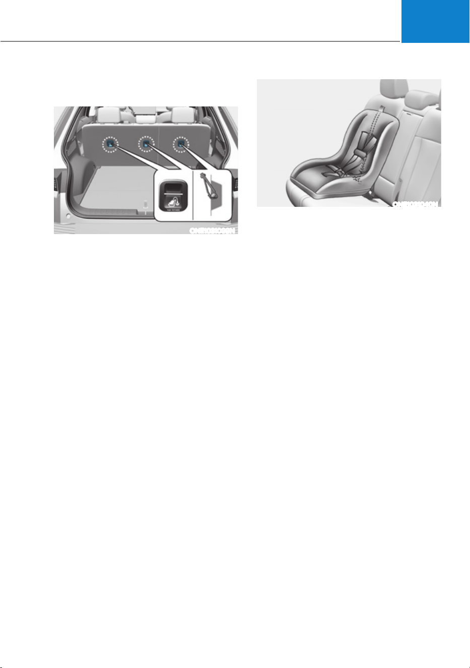
03
3-45
Securing a Child Restraint System
seat with “Tether Anchor” system
ONE1031099N
First secure the child restraint with
the LATCH lower anchors or the seat
belt. If the child restraint manufacturer
recommends that the top tether strap
be attached, attach and tighten the
top tether strap to the top tether strap
anchor.
Child restraint hook holders are located
on the rear of the seatbacks.
ONE1031040N
To install the tether anchor:
1. Route the Child Restraint System
top-tether strap over the seatback.
Route the tether strap under the
head restraint and between the head
restraint posts, or route the tether
strap over the top of the vehicle
seatback. Make sure the strap is not
twisted.
2. Connect the tether strap hook to
the tether anchor, then tighten the
top-tether strap according to the
instructions of your Child Restraint
System’s manufacturer to firmly
attach the Child Restraint System to
the seat.
3. Check that the Child Restraint System
is securely attached to the seat by
pushing and pulling the seat forward-
and-back and side-to-side.

Seats & Safety System
3-46
WARNING
Take the following precautions when
installing the top-tether:
ś Read and follow all installation
instructions provided with your Child
Restraint System.
ś NEVER attach more than one
Child Restraint System to a single
tether anchor. This could cause the
anchorage or attachment to come
loose or break.
ś Do not attach the tether strap to
anything other than the correct
top-tether anchor. It may not work
properly if attached to something
else.
ś Child Restraint System anchors are
designed to withstand only those
loads imposed by correctly fitted
Child Restraint System.
Under no circumstances are the
anchors to be used for adult seat
belts or harnesses or for attaching
other items or equipment to the
vehicle.
Securing a Child Restraint System
with a lap/shoulder belt
WARNING
ALWAYS place a rearward-facing Child
Restraint System in the rear seat of the
vehicle.
Placing a rearward-facing child restraint
in the front seat can result in serious
injury or death if the Child Restraint
System is struck by an inflating air bag.
When not using the LATCH system, all
Child Restraint Systems must be secured
to a rear seat with the lap part of a lap/
shoulder belt.
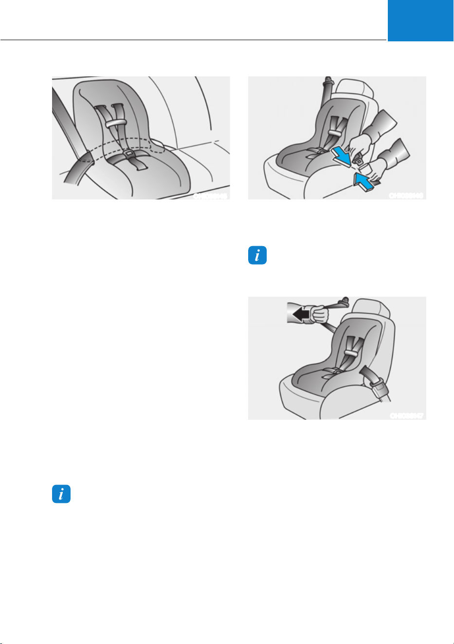
03
3-47
OHI038145
Automatic locking mode
Since all passenger seat belts move
freely under normal conditions and
only lock under extreme or emergency
conditions (emergency locking mode),
you must manually pull the seat belt all
the way out to shift the retractor to the
"Automatic Locking" mode to secure a
Child Restraint System.
The "Automatic Locking" mode will help
prevent the normal movement of the
child in the vehicle from causing the
seat belt to loosen and compromise
the Child Restraint System. To secure a
Child Restraint System, use the following
procedure.
To install a Child Restraint System on the
rear seats, do the following:
1. Place the Child Restraint System on a
rear seat and route the lap/shoulder
belt around or through the Child
Restraint System, following the Child
Restraint System manufacturer’s
instructions. Make sure the seat belt
webbing is not twisted.
Information
When using the rear center seat belt, you
should also refer to the "Rear Seat Belt –
Passenger's 3-point system" section in this
chapter.
OHI038146
2. Fasten the lap/shoulder belt latch
into the buckle. Listen for the distinct
“click” sound.
Information
Position the release button so that it is easy
to access in case of an emergency.
OHI038147
3. Pull the shoulder portion of the
seat belt all the way out. When the
shoulder portion of the seat belt
is fully extended, it will shift the
retractor to the "Automatic Locking"
(child restraint) mode.
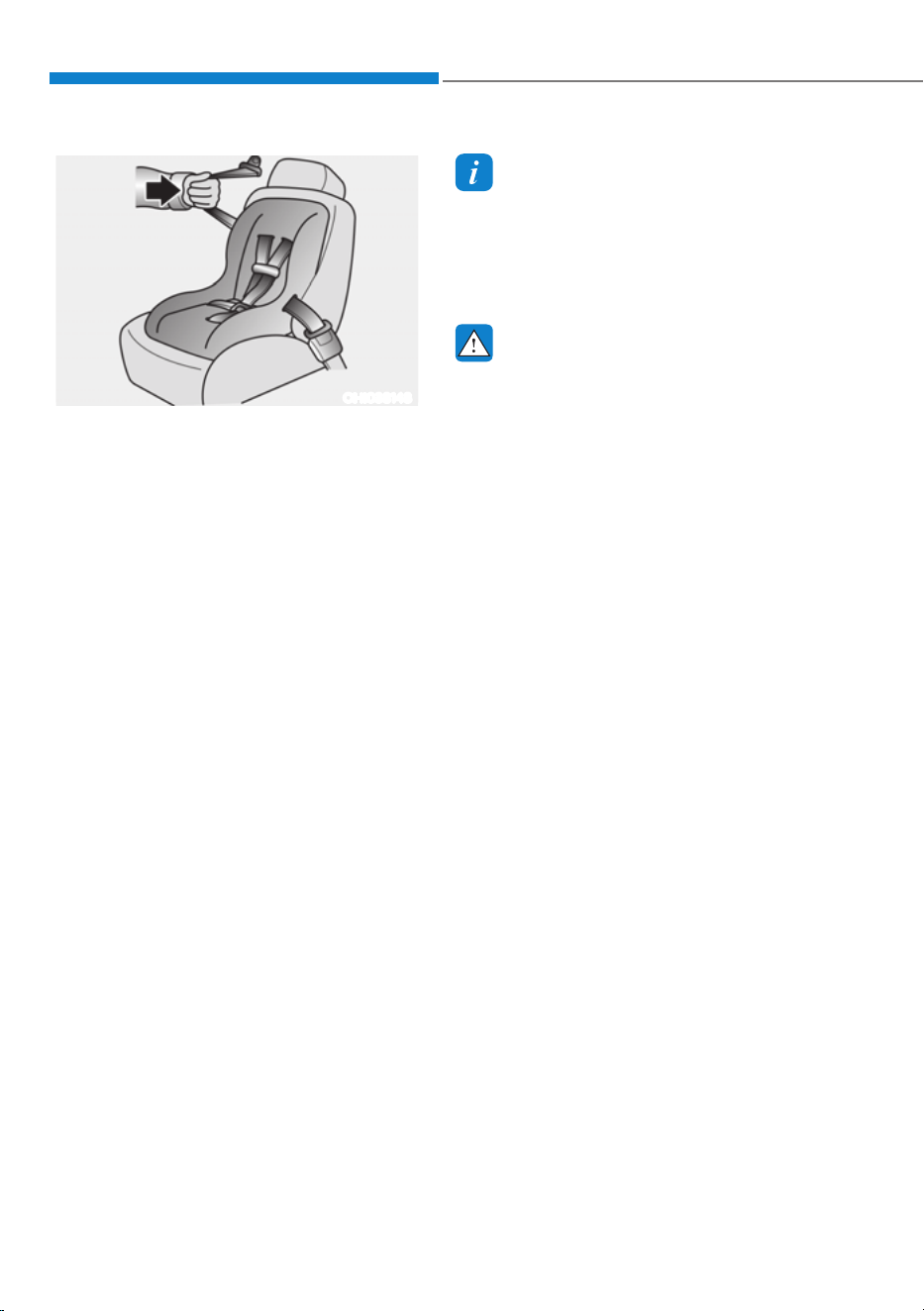
3-48
Seats & Safety System
OHI038148
4. Slowly allow the shoulder portion of
the seat belt to retract and listen for
an audible "clicking" or "ratcheting"
sound. This indicates that the retractor
is in the "Automatic Locking" mode.
If no distinct sound is heard, repeat
steps 3 and 4.
5. Remove as much slack from the belt
as possible by pushing down on the
Child Restraint System while feeding
the shoulder belt back into the
retractor.
6. Push and pull on the Child Restraint
System to confirm that the seat belt
is holding it firmly in place. If it is not,
release the seat belt and repeat steps
2 through 6.
7. Double check that the retractor is in
the "Automatic Locking" mode by
attempting to pull more of the seat
belt out of the retractor. If you cannot,
the retractor is in the "Automatic
Locking" mode.
If your Child Restraint System
manufacturer instructs or recommends
you to use a tether anchor with the lap/
shoulder belt, refer to the previous pages
for more information.
Information
When the seat belt is allowed to retract to
its fully stowed position, the retractor will
automatically switch from the “Automatic
Locking” mode to the emergency lock
mode for normal adult usage.
WARNING
If the retractor is not in the “Automatic
Locking” mode, the child restraint
can move when your vehicle turns or
stops suddenly. A child can be seriously
injured or killed if the child restraint
is not properly anchored in the car,
including manually pulling the seat belt
all the way out to shift the retractor to
the “Automatic Locking” mode.
To remove the Child Restraint System,
press the release button on the buckle
and then pull the lap/shoulder belt out of
the Child Restraint System and allow the
seat belt to retract fully.
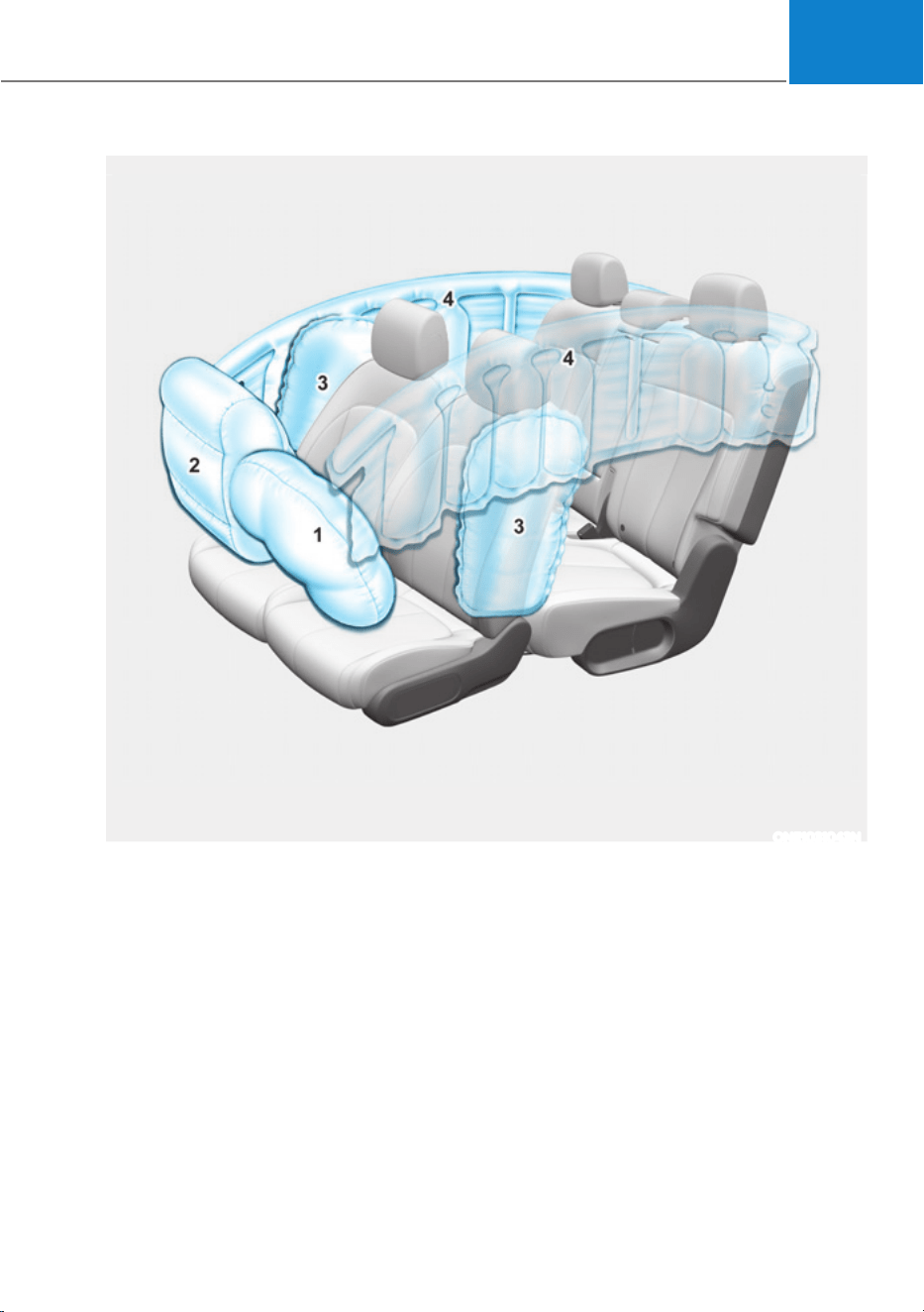
3-49
03
The actual air bags in the vehicle may differ from the illustration.
ONE1031043N
$,5%$*ǘ6833/(0(17$/5(675$,176<67(0
1. Driver’s front air bag
2. Passenger’s front air bag
3. Side air bag
4. Curtain air bag

Seats & Safety System
3-50
The vehicles are equipped with a Supplemental Air Bag System for the driver’s seat and
front passenger’s seats.
The front air bags are designed to supplement the three-point seat belts. For these air
bags to provide protection, the seat belts must be worn at all times when driving.
You can be severely injured or killed in an accident if you are not wearing a seat belt.
Air bags are designed to supplement seat belts, but do not replace them. Also, air bags
are not designed to deploy in every collision. In some accidents, the seat belts are the
only restraint protecting you.
WARNING
AIR BAG SAFETY PRECAUTIONS
ALWAYS use seat belts and Child Restraint Systems - every trip, every time,
everyone! Even with air bags, you can be seriously injured or killed in a collision if
you are improperly belted or not wearing your seat belt when the air bag inflates.
NEVER place a child in any Child Restraint System or booster seat in the front
passenger seat, unless the air bag is deactivated.
An inflating air bag could forcefully strike the infant or child causing serious or fatal
injuries.
ABC - Always Buckle Children under age 13 in the back seat. It is the safest place
for children of any age to ride. If a child age 13 or older must be seated in the front
seat, he or she must be properly belted and the seat should be moved as far back as
possible.
All occupants should sit upright with the seatback in an upright position, centered
on the seat cushion with their seat belt on, legs comfortably extended and their feet
on the floor until the vehicle is parked and the vehicle is turned off. If an occupant
is out of position during an accident, the rapidly deploying air bag may forcefully
contact the occupant causing serious or fatal injuries.
You and your passengers should never sit or lean unnecessarily close to the air bags
or lean against the door or center console.
Move your seat as far back as possible from front air bags, while still maintaining
control of the vehicle. The U.S. National Highway Traffic Safety Administration
(NHTSA) recommends that drivers allow at least 10 inches (25 cm) between the
center of the steering wheel and the chest.
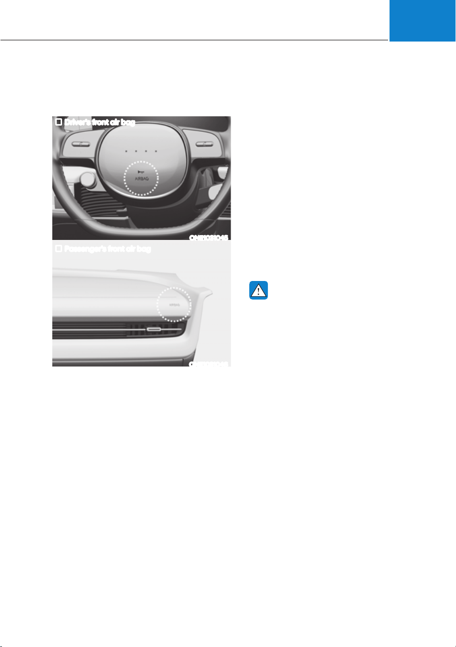
03
3-51
Where are the Air Bags?
Driver’s and passenger’s front air
bags
Driver’s front air bag
ONE1031045
Passenger’s front air bag
ONE1031046
Your vehicle is equipped with a
Supplemental Restraint System (SRS)
and lap/shoulder belts at both the driver
and passenger seating positions.
The SRS consists of air bags which are
located in the center of the steering
wheel and the passenger’s side front
panel pad above the glove box.
The air bags are labeled with the letters
“AIR BAG” embossed on the pad covers.
The purpose of the SRS is to provide the
vehicle’s driver and front passengers with
additional protection than that offered
by the seat belt system alone in case of a
frontal impact of sufficient severity.
The seat belt buckle sensors determine
if the driver and front passenger's seat
belts are fastened. These sensors provide
the ability to control the SRS deployment
based on whether or not the seat belts are
fastened, and how severe the impact is.
The advanced SRS offers the ability to
control the air bag inflation within two
levels. A first stage level is provided for
moderate-severity impacts. A second
stage level is provided for more severe
impacts.
According to the impact severity, and
seat belt usage, the SRS Control Module
(SRSCM) controls the air bag inflation.
Failure to properly wear seat belts can
increase the risk or severity of injury in an
accident.
WARNING
To reduce the risk of serious injury or
death from inflating front air bags, take
the following precautions:
ś Seat belts must be worn at all times
to help keep occupants positioned
properly.
ś Move your seat as far back as
possible from front air bags, while
still maintaining control of the
vehicle.
ś Never lean against the door or center
console.
ś Do not allow the front passenger
to place their feet or legs on the
dashboard.
ś No objects (such as crash pad
cover, mobile phone holder, cup
holder, perfume or stickers) should
be placed over or near the air bag
modules on the steering wheel,
instrument panel, windshield glass,
and the front passenger’s panel
above the glove box. Such objects
could cause harm if the vehicle is in a
crash severe enough to cause the air
bags to deploy.
ś Do not attach any objects on the
front windshield and inside mirror.
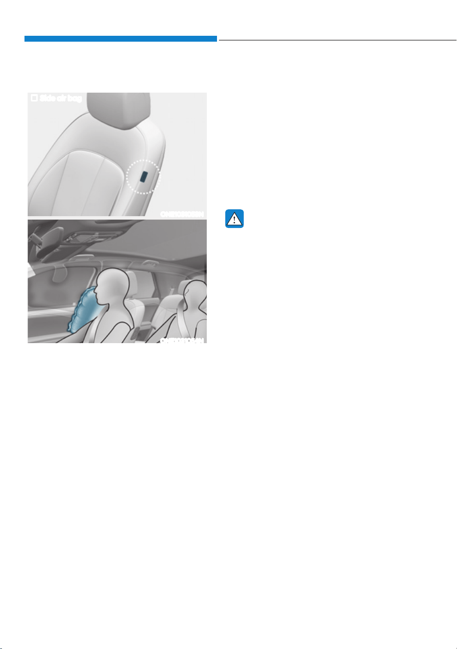
Seats & Safety System
3-52
Side air bags (if equipped)
Side air bag
ONE1031053N
ONE1031054N
Your vehicle is equipped with a side air
bag in each front seat. The purpose of
the air bag is to provide the vehicle’s
driver and the front passenger with
additional protection than that offered by
the seat belt alone.
The side air bags are designed to deploy
during certain side impact collisions,
depending on the crash severity, angle,
speed and point of impact.
The side air bags on both sides of the
vehicle are designed to deploy when a
rollover is detected by a rollover sensor.
(if equipped with rollover sensor)
The side air bags are not designed to
deploy in all side impact or rollover
situations.
The side air bags are designed to deploy
during certain side impact collisions,
depending on the crash severity.
For vehicles equipped with a rollover
sensor the side and/or curtain air bags
and pre-tensioners on both sides of
the vehicle may deploy if a rollover or
possible rollover is detected.
The side air bags are not designed to
deploy in all side impact or rollover
situations.
WARNING
To reduce the risk of serious injury or
death from an inflating side air bag,
take the following precautions:
ś Seat belts must be worn at all times
to help keep occupants positioned
properly.
ś Do not allow passengers to lean their
heads or bodies onto doors, put their
arms on the doors, stretch their arms
out of the window, or place objects
between the doors and seats.
ś Hold the steering wheel at the 9
o’clock and 3 o’clock positions, to
minimize the risk of injuries to your
hands and arms.
ś Do not use any accessory seat
covers. This could reduce or prevent
the effectiveness of the system.
ś Do not hang other objects except
clothes. In an accident it may cause
vehicle damage or personal injury
especially when air bag is inflated.
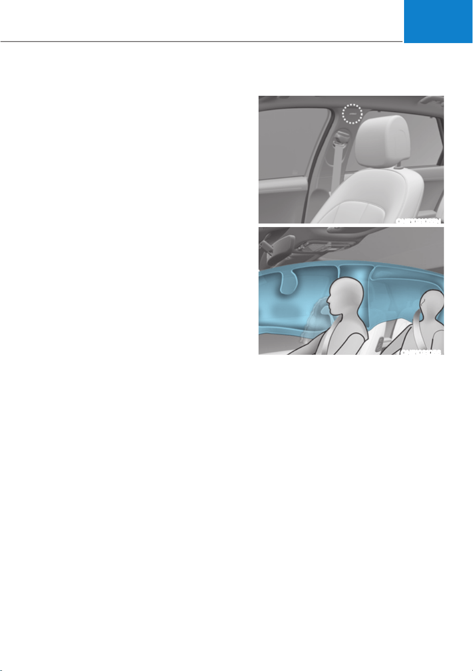
03
3-53
ś Do not place any objects over the
air bag or between the air bag and
yourself. Also, do not attach any
objects around the area the air bag
inflates such as the door, side door
glass, front and rear pillar.
ś Do not place any objects between
the door and the seat. They may
become dangerous projectiles if the
side air bag inflates.
ś Do not install any accessories on the
side or near the side air bags.
ś Do not cause impact to the doors
when the Start/Stop button is in the
ON or START position as this may
cause the side air bags to inflate.
ś If the seat or seat cover is damaged,
have the system serviced by an
authorized HYUNDAI dealer.
Curtain air bags
ONE1031055N
ONE1031056
Curtain air bags are located along both
sides of the roof rails above the front and
rear doors.
They are designed to help protect the
heads of the front seat occupants and
the rear outboard seat occupants in
certain side impact collisions.
The curtain air bags are designed to
deploy during certain side impact
collisions, depending on the crash
severity.
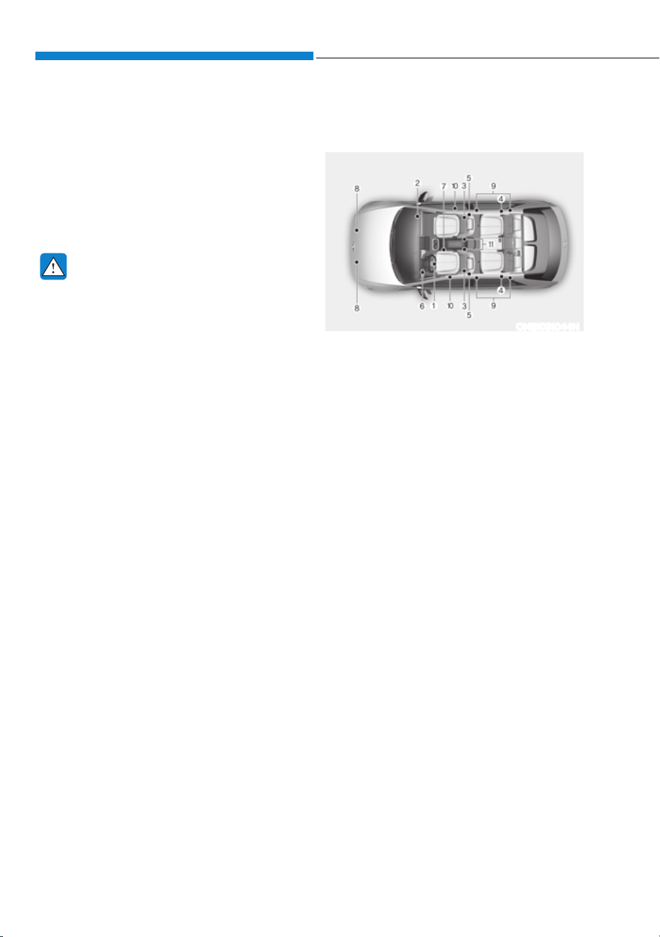
Seats & Safety System
3-54
For vehicles equipped with a rollover
sensor the side and/or curtain air bags
and pre-tensioners on both sides of
the vehicle may deploy if a rollover or
possible rollover is detected.
The curtain air bags are not designed
to deploy in all side impact or rollover
situations.
WARNING
To reduce the risk of serious injury or
death from an inflating curtain air bag,
take the following precautions:
ś All seat occupants must wear
seat belts at all times to help keep
occupants positioned properly.
ś Properly secure Child Restraint
System as far away from the door as
possible.
ś Do not place any objects over the air
bag. Also, do not attach any objects
around the area the air bag inflates
such as the door, side door glass,
front and rear pillar, roof side rail.
ś Do not hang other objects except
clothes, especially hard or breakable
objects.
In an accident, it may cause vehicle
damage or personal injury.
ś Do not allow passengers to lean their
heads or bodies onto doors, put their
arms on the doors, stretch their arms
out of the window, or place objects
between the doors and seats.
ś Do not open or repair the side curtain
air bags.
How does the Air Bags System
Operate?
ONE1031044N
The SRS consists of the following
components:
(1) Driver’s front air bag module
(2) Passenger’s front air bag module
(3) Side air bag modules
(4) Curtain air bag modules
(5) Front retractor pre-tensioner
(6) Air bag warning light
(7) SRS control module (SRSCM) /
Rollover sensor
(8) Front impact sensors
(9)
Side impact sensors (acceleration)
(10)
Side impact sensors (pressure)
(11)
Driver’s and front passenger’s seat
belt buckle sensors.

03
3-55
The SRSCM (Supplemental Restraint
System Control Module) continually
monitors all SRS components while the
Start/Stop button is ON to determine if a
crash impact is severe enough to require
air bag deployment or pre-tensioner seat
belt deployment.
SRS warning light
The SRS (Supplemental Restraint System)
air bag warning light on the instrument
panel displays the air bag symbol
depicted in the illustration. The system
checks the air bag electrical system for
malfunctions. The light indicates that
there is a potential problem with your
air bag system, which could include
your side and/or curtain air bags used
for rollover protection (if equipped with
rollover sensor).
WARNING
If your SRS malfunctions, the air bag
may not inflate properly during an
accident increasing the risk of serious
injury or death.
If any of the following conditions occur,
your SRS is malfunctioning:
ś The light does not turn on for
approximately three to six seconds
when the Start/Stop button is in the
ON position.
ś The light stays on after illuminating
for approximately three to six
seconds.
ś The light comes on while the vehicle
is in motion.
ś The light blinks when the vehicle is
running.
Have an authorized HYUNDAI dealer
inspect the SRS as soon as possible if
any of these conditions occur.
During a moderate to severe frontal
collision, sensors will detect the
vehicle’s rapid deceleration. If the rate of
deceleration is high enough, the control
unit will inflate the front air bags, at the
time and with the force needed.
The front air bags help protect the driver
and front passenger by responding to
frontal impacts in which seat belts alone
cannot provide adequate restraint. When
needed, the side air bags help provide
protection in the event of a side impact
or rollover by supporting the side upper
body area.
ś Air bags are activated (able to inflate
if necessary) only when the Start/Stop
button is in the ON or START position,
and it can be activated within about 3
minutes after the vehicle is turned off.
ś Air bags inflate in the event of certain
frontal or side collisions to help
protect the occupants from serious
physical injury.
ś Generally, air bags are designed to
inflate based upon the severity of a
collision, its direction, or etc. These
two factors determine whether
the sensors produce an electronic
deployment/inflation signal.
ś The front air bags will completely
inflate and deflate in an instant. It is
virtually impossible for you to see the
air bags inflate during an accident. It is
much more likely that you will simply
see the deflated air bags hanging out
of their storage compartments after
the collision.

Seats & Safety System
3-56
ś In addition to inflating in serious side
collisions, vehicles equipped with a
rollover sensor, side and/or curtain air
bags will inflate if the sensing system
detects a rollover.
When a rollover is detected, curtain
air bags will remain inflated longer to
help provide protection from ejection,
especially when used in conjunction
with the seat belts. (if equipped with a
rollover sensor)
ś To help provide protection, the air
bags must inflate rapidly. The speed
of air bag inflation is a consequence
of extremely short time in which
to inflate the air bag between the
occupant and the vehicle structures
before the occupant impacts those
structures. This speed of inflation
reduces the risk of serious or life-
threatening injuries and is thus a
necessary part of air bag design.
However, the rapid air bag inflation
can also cause injuries which can
include facial abrasions, bruises and
broken bones because the inflation
speed also causes the air bags to
expand with a great deal of force.
ś There are even circumstances under
which contact with the air bag can
cause fatal injuries, especially if the
occupant is positioned excessively
close to the air bag.
You can take steps to reduce the risk
of being injured by an inflating air bag.
The greatest risk is sitting too close to
the air bag. An air bag needs about 10
in. (25 cm) of space to inflate. NHTSA
recommends that drivers allow at least
10 in. (25 cm) between the center of the
steering wheel and the chest.
WARNING
To reduce the risk of serious injury or
death from an inflating air bag, take the
following precautions:
ś NEVER place a child restraint in the
front passenger seat.
Always properly restrain children
under age 13 in the rear seats of the
vehicle.
ś Adjust the front passenger’s and
driver's seats as far to the rear as
possible while allowing you to
maintain full control of the vehicle.
ś Hold the steering wheel with
hands at the 9 o'clock and 3 o'clock
positions.
ś Never place anything or anyone
between the air bag and the seat
occupant.
ś Do not allow the front passenger
to place their feet or legs on the
dashboard.
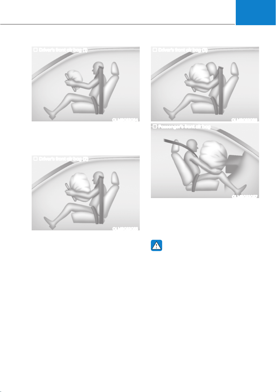
03
3-57
Driver’s front air bag (1)
OLMB033054
When the SRSCM detects a sufficiently
severe impact to the front of the vehicle,
it will automatically deploy the front air
bags.
Driver’s front air bag (2)
OLMB033055
Upon deployment, tear seam molded
directly into the pad cover will separate
under pressure from the expansion of the
air bags. Further opening of the covers
allows full inflation of the air bags.
A fully inflated air bag, in combination
with a properly worn seat belt, slows the
driver’s or the front passenger’s forward
motion, reducing the risk of head and
chest injury.
Driver’s front air bag (3)
OLMB033056
Passenger’s front air bag
OLMB033057
After complete inflation, the air bag
immediately starts deflating, enabling
the driver to maintain forward visibility
and the ability to steer or operate other
controls.
WARNING
To prevent objects from becoming
dangerous projectiles when the
passenger’s air bag inflates:
ś Do not install or place any objects
(drink holder, CD holder, stickers,
etc.) on the front passenger’s panel
above the glove box where the
passenger’s air bag is located.
ś Do not install a container of liquid
air freshener near the instrument
cluster or on the instrument panel
surface.

Seats & Safety System
3-58
What to Expect After an Air Bag
Inflates
After a frontal or side air bag inflates, it
will deflate very quickly. Air bag inflation
will not prevent the driver from seeing
out of the windshield or being able
to steer. Curtain air bags may remain
partially inflated for some time after they
deploy.
WARNING
After an air bag inflates, take the
following precautions:
ś Open your windows and doors as
soon as possible after impact to
reduce prolonged exposure to the
smoke and powder released by the
inflating air bag.
ś Do not touch the air bag storage
area’s internal components
immediately after an air bag has
inflated. The parts that come into
contact with an inflating air bag may
be very hot.
ś Always wash exposed skin areas
thoroughly with cold water and mild
soap.
ś Have an authorized HYUNDAI dealer
replaced the air bag immediately
after deployment. Air bags are
designed to be used only once.
Noise and smoke from inflating air
bag
When the air bags inflate, they make a
loud noise and may produce smoke and
powder in the air inside of the vehicle.
This is normal and is a result of the
ignition of the air bag inflator. After the
air bag inflates, you may feel substantial
discomfort in breathing because of the
contact of your chest with both the seat
belt and the air bag, as well as from
breathing the smoke and powder. The
powder may aggravate asthma for some
people. If you experience breathing
problems after an air bag deployment,
seek medical attention immediately.
Though the smoke and powder are
nontoxic, they may cause irritation to
the skin, eyes, nose, throat, etc. If this is
the case, wash and rinse with cold water
immediately and seek medical attention
if the symptoms persist.
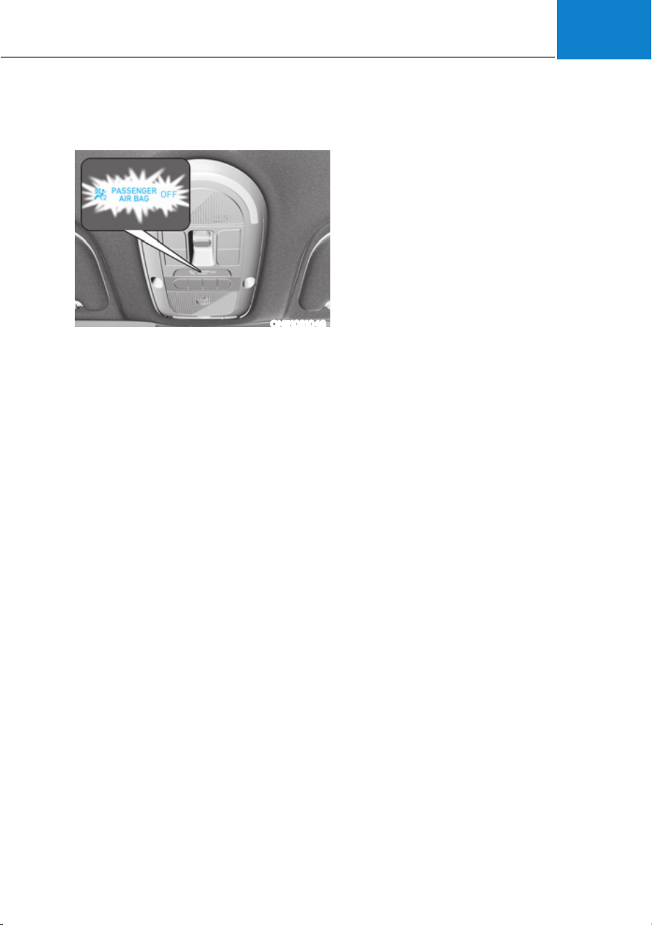
03
3-59
Occupant Classification System
(OCS)
ONE1031048
Your vehicle is equipped with an
Occupant Classification System (OCS) in
the front passenger’s seat.
Main components of the Occupant
Classification System
ś A detection device located within the
front passenger seat cushion.
ś Electronic system to help determine
whether the passenger air bag
systems should be activated or
deactivated.
ś An indicator light located on the
instrument panel which illuminates
the words “PASSENGER AIR BAG OFF”
indicating the front passenger air bag
system is deactivated.
ś The instrument panel air bag indicator
light is interconnected with the OCS.

Seats & Safety System
3-60
The OCS is designed to help detect
the presence of a properly-seated
front passenger and determine if the
passenger’s front air bag should be
enabled (may inflate) or not.
The purpose is to help reduce the risk
of injury or death from an inflating air
bag to certain front passenger seat
occupants, such as children, by requiring
the air bag to be automatically turned
OFF.
For example, if a child restraint of the
type specified in the regulations is on the
seat, the occupant classification sensor
can detect it and cause the air bag to
turn OFF.
Front passenger seat adult occupants
who are properly seated and wearing the
seat belt properly, should not cause the
passenger air bag to be automatically
turned OFF. For smaller adults it may turn
OFF, however, if the occupant does not
sit in the seat properly (for example, by
not sitting upright, by sitting on the edge
of the seat, or by otherwise being out of
position), this could cause the sensor to
turn the air bag OFF.
You will find the “PASSENGER AIR BAG
OFF” indicator on the overhead console
panel. This system detects the conditions
1-4 in the following table and activates or
deactivates the front passenger air bag
based on these conditions.
Always be sure that you and all vehicle
occupants are seated properly and
wearing the seat belt properly for the
most effective protection by the air bag
and the seat belt.
The OCS may not function properly if the
passenger takes actions which can affect
the classification system. These include:
ś Failing to sit in an upright position.
ś Leaning against the door or center
console.
ś Sitting towards the sides of the front
of the seat.
ś Putting their legs on the dashboard or
resting them on other locations which
reduce the passenger weight on the
front seat.
ś Wearing the seat belt improperly.
ś Reclining the seatback.
ś Wearing thick clothes like ski wear or
hip protection wear.
ś Putting an additional thick cushion on
the seat.
ś Putting electrical devices (for
example, notebook, satellite radio) on
the seat with inverter charging.

3-61
03
Condition and operation in the front passenger Occupant Classification System
Condition detected by the
occupant classification system
Indicator/Warning light Devices
“PASSENGER
AIR BAG OFF”
indicator light
SRS warning
light
Front
passenger air
bag
1. Adult
*1
Off Off Activated
2. Infant
*2
or child restraint
system with 12 months old
*3 *4
On Off Deactivated
3. Unoccupied
On Off Deactivated
4. Malfunction in the system
Off On Activated
*1 :
The system judges a person of adult size as an adult. When a smaller adult sits in the
front passenger seat, the system may recognize him/her as a child depending on his/her
physique and posture.
*2 :
Do not allow children to ride in the front passenger seat. When a larger child who has
outgrown a child restraint system sits in the front passenger seat, the system may
recognize him/her as an adult depending upon his/her physique or sitting position.
*3 :
Never install a child restraint system on the front passenger seat.
*4 :
The PASSENGER AIR BAG “OFF” indicator may turn on or off when a child above 12
months to 12 years old (with or without child restraint system) sits in the front passenger
seat. This is a normal condition.
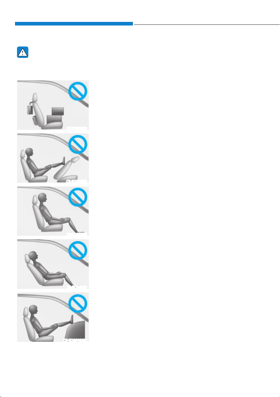
Seats & Safety System
3-62
WARNING
Riding in an improper position or placing weight on the front passenger’s seat when
it is unoccupied by a passenger adversely affects the OCS. To reduce the risk of
serious injury or death:
OHI038163
ś NEVER put a heavy load in the front seat or seatback
pocket, or hang any items on the front passenger
seat.
OHI038156
ś NEVER place your feet on the front passenger
seatback.
OHI038155
ś NEVER sit with your hips shifted towards the front of
the seat.
OHI038157
ś NEVER ride with the seatback reclined when the
vehicle is moving.
OHI039192N
ś NEVER place your feet or legs on the dashboard.
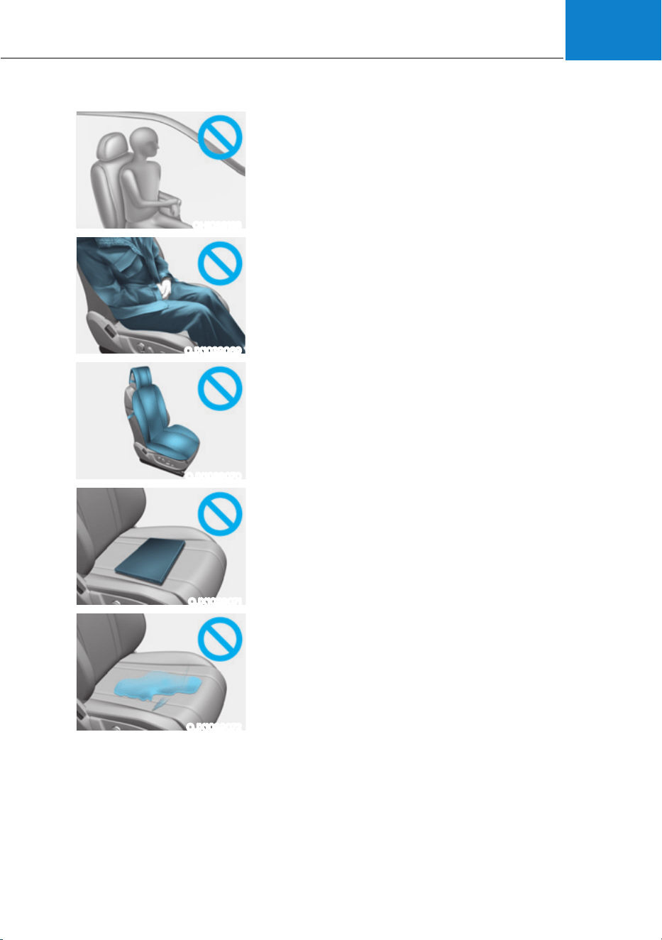
03
3-63
OHI038158
ś NEVER lean on the door or center console or sit on
one side of the front passenger seat.
OJX1039069
ś Do not sit on the passenger seat wearing heavily
padded clothes such as ski wear and hip protector.
OJX1039070
ś Do not use car seat accessories such as thick blankets
and cushions which cover up the car seat surface.
OJX1039071
ś Do not place electronic devices such as laptops, DVD
player, or conductive materials such as water bottles
on the passenger seat.
ś Do not use electronic devices such as laptops and
satellite radios which use inverter chargers.
OJX1039072
ś If large quantity of liquid has been spilled on the
passenger seat, the air bag warning light may
illuminate or malfunction.
Therefore, make sure the seat has been completely
dried before driving the vehicle.
ś Do not place sharp objects on the front passenger seat. These may damage the
occupant detection system, if they puncture the seat cushion.
ś Do not place any items under the front passenger seat.
ś When changing or replacing the seat or seat cover, use original items only.
The OCS has been developed based on using original HYUNDAI car seats only.
Altering or changing the authentic parts may result in system malfunction and
increase risk of injury when in collision. Any of the above could interfere with the
proper operation of the OCS sensor thereby increasing the risk of an injury in an
accident.
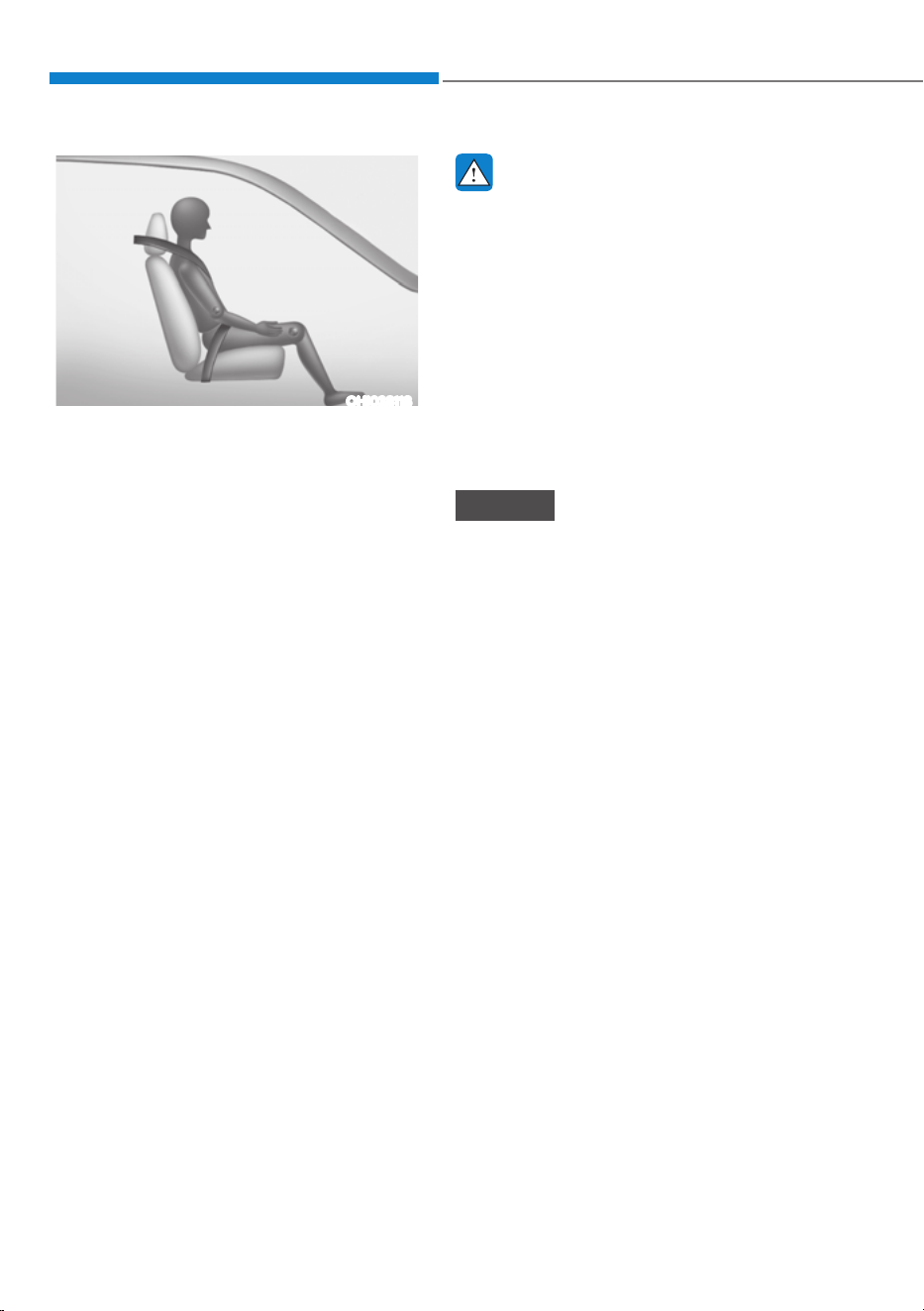
Seats & Safety System
3-64
OHI038118
Proper seated position for OCS
If the “PASSENGER AIR BAG OFF”
indicator is on when an adult is seated
in the front passenger seat, place the
Start/Stop button in the OFF position and
ask the passenger to sit properly (sitting
upright with the seat back in an upright
position, centered on the seat cushion
with their seat belt on, legs comfortably
extended and their feet on the floor).
Restart the vehicle and have the person
remain in that position. This will allow
the system to detect the person and
to enable the passenger air bag. If the
“PASSENGER AIR BAG OFF” indicator is
still on, ask the passenger to move to the
rear seat.
WARNING
NEVER allow an adult passenger to ride
in the front passenger seat when the
“PASSENGER AIR BAG OFF” indicator
is illuminated. During a collision, the
air bag will not inflate if the indicator
is illuminated. Have your passenger
reposition themselves in the seat. If the
“PASSENGER AIR BAG OFF” indicator
remains illuminated after the passenger
repositions themselves properly
and the vehicle is restarted, have
the passenger move to the rear seat
because the air bag will not inflate.
NOTICE
The “PASSENGER AIR BAG OFF”
indicator generally illuminates for
approximately 4 seconds after the
Start/Stop button is in the ON or START
position. But, if the START/STOP button
is pressed to the ON or START position
within 3 minutes after the vehicle is
turned OFF, the indicator does not
illuminate. If the front passenger seat
is occupied, the OCS will then classify
the front passenger after several more
seconds.
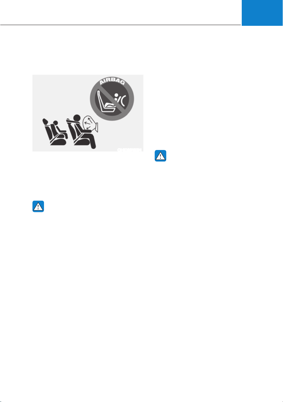
03
3-65
Do not install a Child Restraint
System on the Front Passenger’s
Seat
OHI039193N
Even though your vehicle is equipped
with the OCS, never install a child
restraint in the front passenger’s seat.
An inflating air bag can forcefully strike a
child or child restraint resulting in serious
or fatal injury.
WARNING
NEVER use a rearward facing Child
Restraint on a seat protected by an
ACTIVE AIRBAG in front of it, DEATH
or SERIOUS INJURY to the CHILD can
occur.
Why didn’t my air bag go off in a
collision?
There are certain types of accidents in
which the air bag would not be expected
to provide additional protection. These
include rear impacts, second or third
collisions in multiple impact accidents,
as well as low speed impacts. Damage to
the vehicle indicates a collision energy
absorption, and is not an indicator of
whether or not an air bag should have
inflated.
Air bag collision sensors
WARNING
To reduce the risk of an air bag
deploying unexpectedly and causing
serious injury or death:
ś Do not hit or allow any objects to
impact the locations where air bags
or sensors are installed.
ś Do not perform maintenance on or
around the air bag sensors. If the
location or angle of the sensors is
altered, the air bags may deploy
when they should not or may not
deploy when they should.
ś Installing bumper guards with non-
genuine Hyundai or non-equivalent
parts may adversely affect the
collision and airbag deployment
performance.
To ensure correct function of the
airbag system, have the bumper
replaced with genuine Hyundai part
or the equivalent (of the genuine
part) specified for your vehicle.
ś Press the Start/Stop button to the
OFF or ACC position and wait for 3
minutes when the vehicle is being
towed to prevent inadvertent air bag
deployment.
ś Have all air bag repairs conducted by
an authorized HYUNDAI dealer.
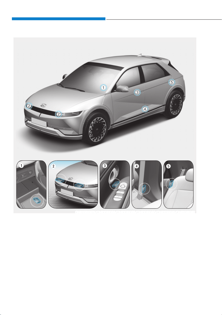
Seats & Safety System
3-66
ONE1031057K/ONE1031058/ONE1031059/ONE1031060/ONE1031061/ONE1031062
1. SRS control module / Rollover sensor
2. Front impact sensor
3. Side impact sensor (Pressure)
4. Side impact sensor (Acceleration)
5. Side impact sensor (Acceleration)
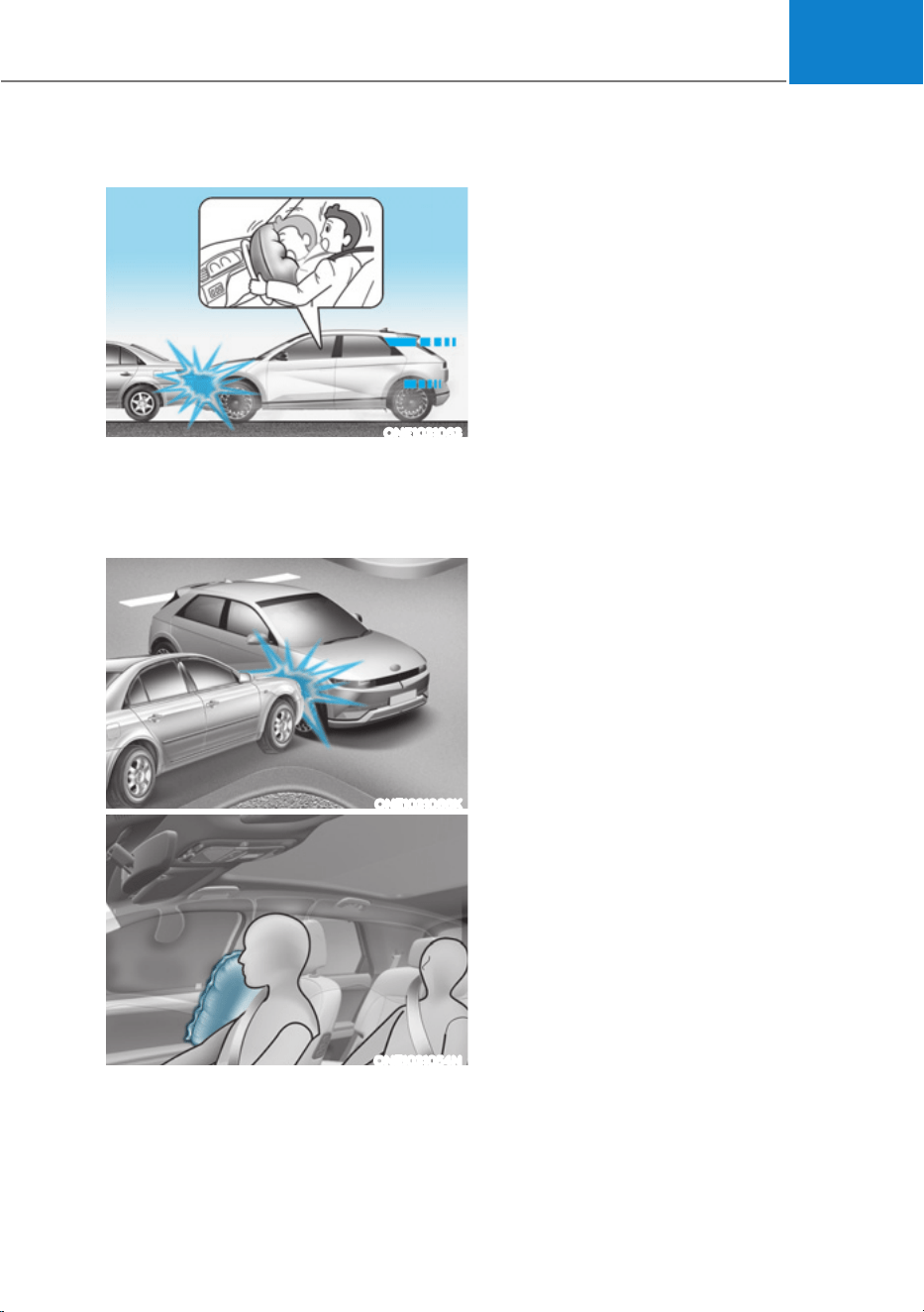
03
3-67
Air bag inflation conditions
ONE1031063
Front air bags
Front air bags are designed to inflate
in a frontal collision depending on the
severity of impact of the front collision.
ONE1031066K
ONE1031054N
Side and curtain air bags
Side and curtain air bags are designed
to inflate when an impact is detected by
side collision sensors depending on the
severity of impact resulting from a side
impact collision.
Although the driver’s and front
passenger’s air bags are designed to
inflate in frontal collisions, they also may
inflate in other types of collisions if the
front impact sensors detect a sufficient
impact. Side and curtain air bags are
designed to inflate in side impact
collisions, but they may inflate in other
collisions if the side impact sensors
detect a sufficient impact.
Also, the side and curtain air bags are
designed to inflate when a rollover
is detected by a rollover sensor (if
equipped with rollover sensor).
If the vehicle chassis is impacted by
bumps or objects on unimproved roads,
the air bags may deploy. Drive carefully
on unimproved roads or on surfaces not
designed for vehicle traffic to prevent
unintended air bag deployment.
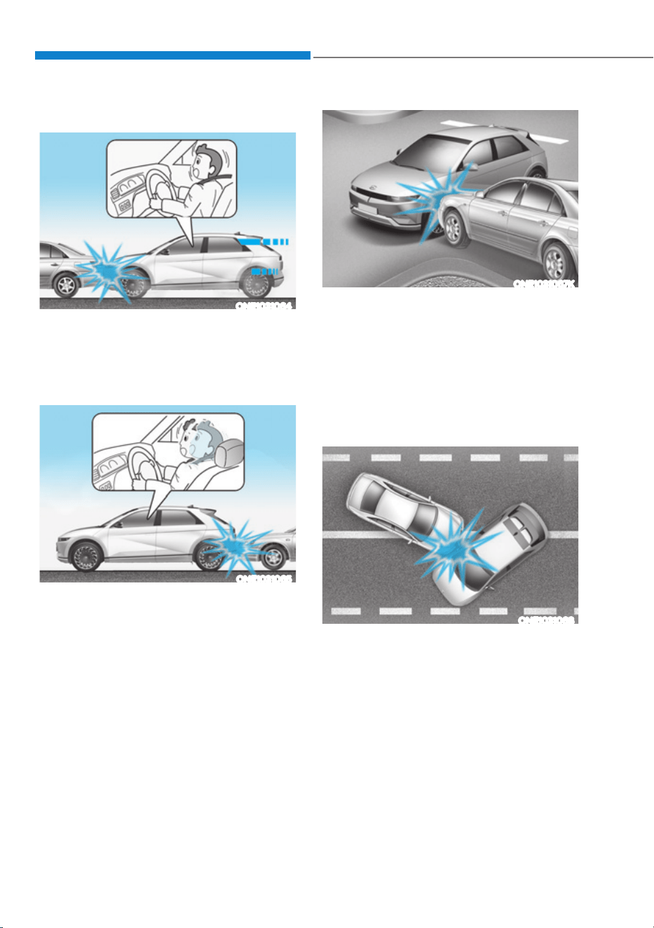
Seats & Safety System
3-68
Air bag non-inflation conditions
ONE1031064
In certain low-speed collisions the air
bags may not deploy. The air bags are
designed not to deploy in such cases
because they may not provide benefits
beyond the protection of the seat belts.
ONE1031065
Front air bags are not designed to inflate
in rear collisions, because occupants
are moved backward by the force of the
impact. In this case, inflated air bags
would not provide any additional benefit.
ONE1031067K
Front air bags may not inflate in side
impact collisions, because occupants
move in the direction of the collision,
and thus in side impacts, front air bag
deployment would not provide additional
occupant protection.
However, side and curtain air bags may
inflate depending on the severity of
impact.
ONE1031068
In an angled collision, the force of impact
may direct the occupants in a direction
where the air bags would not be able to
provide any additional benefit, and thus
the sensors may not deploy any air bags.
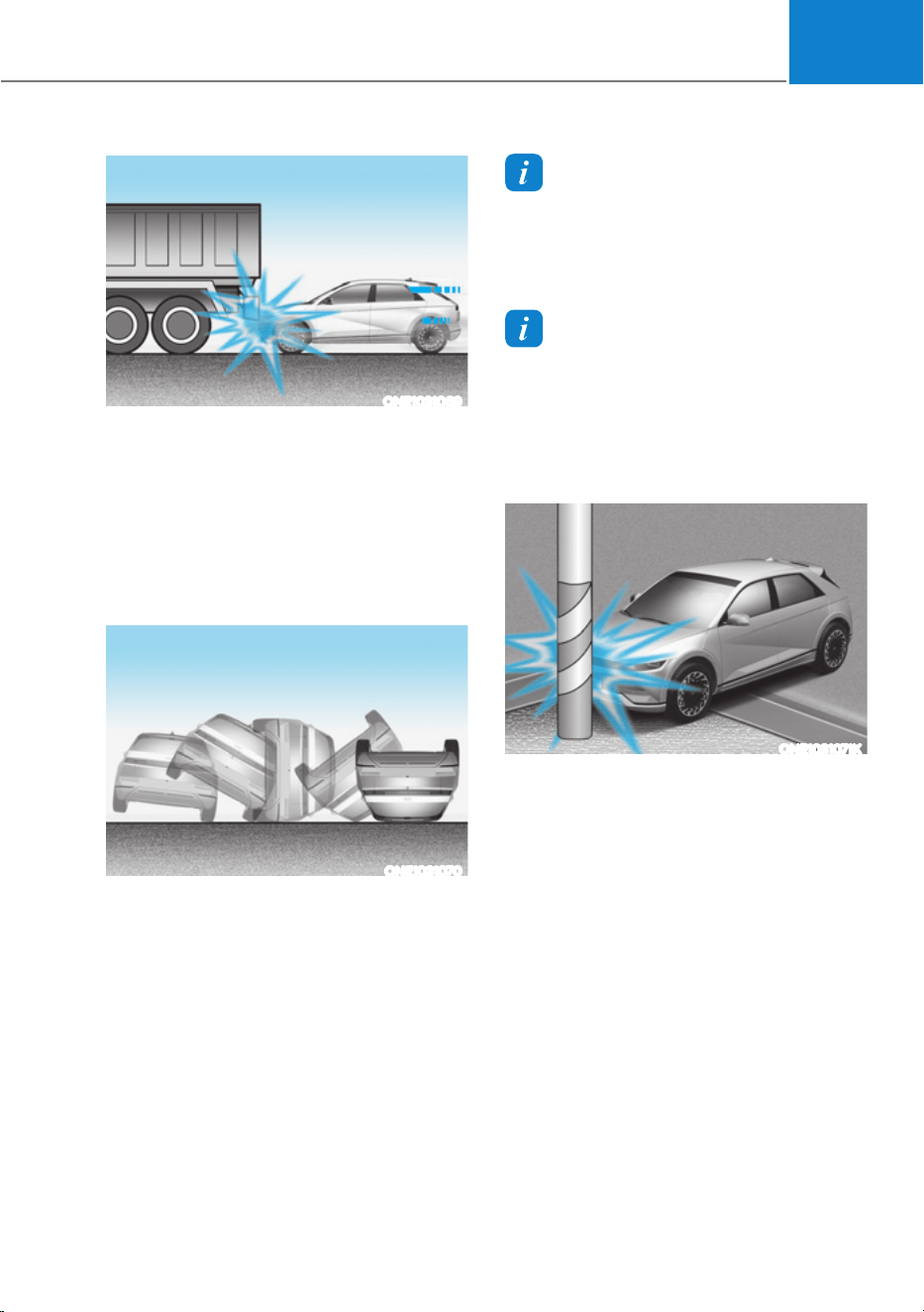
03
3-69
ONE1031069
Just before impact, drivers often brake
heavily. Such heavy braking lowers the
front portion of the vehicle causing it
to “ride” under a vehicle with a higher
ground clearance. Air bags may not
inflate in this “underride” situation
because deceleration forces that are
detected by sensors may be significantly
reduced by such “underride” collisions.
ONE1031070
Front air bags may not inflate in
rollover accidents because front air bag
deployment would not provide additional
occupant protection.
Information
With rollover sensor
The side and curtain air bags may inflate
in a rollover situation, when it is detected
by the rollover sensor.
Information
Without rollover sensor
The side and/or curtain air bags may
inflate when the vehicle is rolled over
by a side impact collision, if the vehicle
is equipped with side and/or curtain air
bags.
ONE1031071K
Air bags may not inflate if the vehicle
collides with objects such as utility poles
or trees, where the point of impact is
concentrated and the collision energy is
absorbed by the vehicle structure.

Seats & Safety System
3-70
SRS Care
The SRS is virtually maintenance-free
and there are no parts you can safely
service by yourself. If the SRS air bag
warning light does not illuminate
when the Start/Stop button is in the
ON position, or continuously remains
on, have the system be immediately
inspected by an authorized HYUNDAI
dealer.
We recommend any work on the SRS
system, such as removing, installing,
repairing, or any work on the steering
wheel, the front passenger’s panel, front
seats and roof rails be performed by an
authorized HYUNDAI dealer. Improper
handling of the SRS system may result in
serious personal injury.
WARNING
To reduce the risk of serious injury or
death take the following precautions:
ś Do not attempt to modify or
disconnect the SRS components or
wiring, including the addition of any
kind of badges to the pad covers or
modifications to the body structure.
ś Do not place objects over or near
the air bag modules on the steering
wheel, instrument panel, and the
front passenger’s panel above the
glove box.
ś Clean the air bag pad covers with
a soft cloth moistened with plain
water. Solvents or cleaners could
adversely affect the air bag covers
and proper deployment of the
system.
ś Have the inflated air bags be
replaced by an authorized HYUNDAI
dealer.
ś If components of the air bag system
must be discarded, or if the vehicle
must be scrapped, certain safety
precautions must be observed.
Consult an authorized HYUNDAI
dealer for the necessary information.
Failure to follow these precautions
could increase the risk of personal
injury.
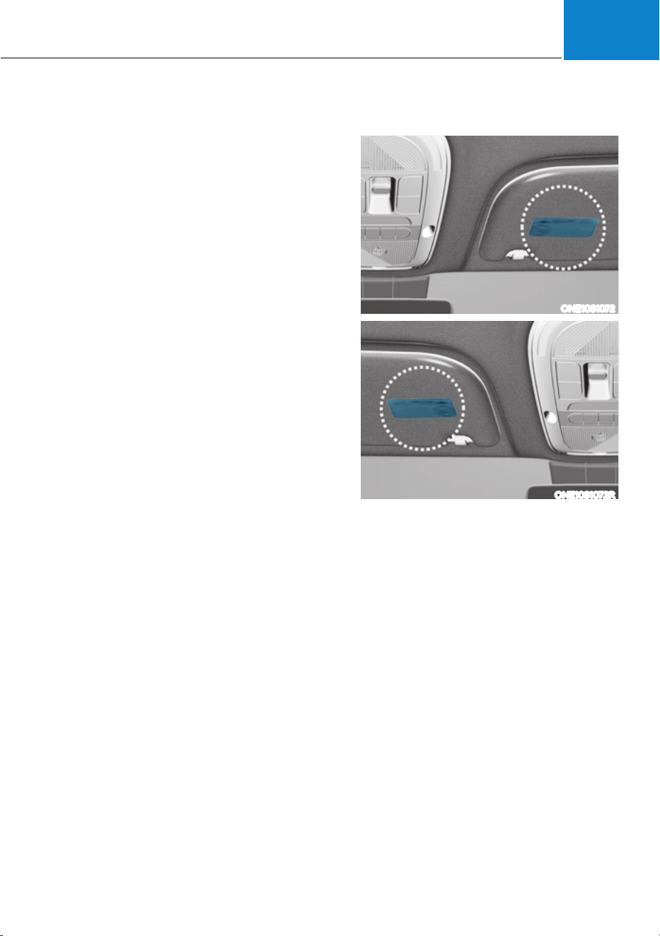
03
3-71
Additional Safety Precautions
Passengers should not move out of
or change seats while the vehicle is
moving. A passenger who is not wearing
a seat belt during a crash or emergency
stop can be thrown against the inside of
the vehicle, against other occupants, or
be ejected from the vehicle.
Do not use any accessories on seat
belts. Devices claiming to improve
occupant comfort or reposition the seat
belt can reduce the protection provided
by the seat belt and increase the chance
of serious injury in a crash.
Do not modify the front seats.
Modification of the front seats could
interfere with the operation of the
supplemental restraint system sensing
components or side air bags.
Do not place items under the front
seats. Placing items under the front seats
could interfere with the operation of the
supplemental restraint system sensing
components and wiring harnesses.
Do not cause impact to the doors.
Impact to the doors when the Start/Stop
button is in the ON or START position
may cause the air bags to inflate.
Modifications to accommodate
disabilities. If you require modification
to your vehicle to accommodate
a disability, contact the HYUNDAI
Customer Connect Center at 800-633-
5151.
Adding equipment to or modifying
your air bag equipped vehicle
If you modify your vehicle by changing
your vehicle’s frame, bumper system,
front end or side sheet metal or ride
height, this may affect the operation of
your vehicle’s air bag system.
Air Bag Warning Labels
ONE1031072
ONE1031072R
Air bag warning labels, required by the
U.S. National Highway Traffic Safety
Administration (NHTSA), are attached
to alert the driver and passengers of
potential risks of the air bag system. Be
sure to read all of the information about
the air bags that are installed on your
vehicle in this Owners Manual.

4
4. Instrument Cluster
Instrument Cluster ............................................................................................ 4-4
Instrument Cluster Control ..........................................................................................4-5
Instrument panel illumination ...................................................................................4-5
Gauges and Meters ......................................................................................................4-5
Speedometer .............................................................................................................4-5
Power/Charge Gauge ................................................................................................. 4-6
State of Charge (SOC) Gauge for High Voltage Battery ........................................... 4-6
Outside temperature gauge ...................................................................................... 4-7
Odometer .................................................................................................................. 4-8
Distance to empty .................................................................................................... 4-8
Reduction Gear Shift Indicator ................................................................................... 4-9
Regenerative braking level indicator ....................................................................... 4-9
Warning and Indicator Lights ..................................................................................... 4-9
Ready indicator ......................................................................................................... 4-9
Service warning light ................................................................................................ 4-9
Power down indicator light ..................................................................................... 4-10
Charging indicator light ........................................................................................... 4-10
High voltage battery level warning light ................................................................ 4-10
Seat belt warning light ............................................................................................ 4-10
Air bag warning light ................................................................................................ 4-11
Regenerative brake warning light ............................................................................ 4-11
Parking brake & brake fluid warning light ............................................................... 4-11
Anti-lock Brake System (ABS) warning light .......................................................... 4-12
Electronic Brake Force Distribution (EBD) system warning light ......................... 4-12
Electric Power Steering (EPS) warning light .......................................................... 4-13
Master warning light ................................................................................................ 4-13
Electronic Parking Brake (EPB) warning light ........................................................ 4-14
Low tire pressure warning light .............................................................................. 4-14
Forward safety warning light .................................................................................. 4-15
Lane safety indicator light ...................................................................................... 4-15
All Wheel Drive (AWD) warning light ...................................................................... 4-15
LED headlight warning light .................................................................................... 4-16
Icy road warning light .............................................................................................. 4-16
Electronic Stability Control (ESC) indicator light ....................................................4-17
Electronic Stability Control (ESC) OFF indicator light ............................................4-17
Immobilizer indicator light .......................................................................................4-17
Turn signal indicator light ........................................................................................ 4-18
High beam indicator light ....................................................................................... 4-18
Light ON indicator light ........................................................................................... 4-18
High Beam Assist indicator light (if equipped) ...................................................... 4-19
AUTO HOLD indicator light ..................................................................................... 4-19

4
LCD Display Messages ............................................................................................... 4-19
Shift to P ................................................................................................................... 4-19
Low key battery ....................................................................................................... 4-19
Press START button while turning wheel ............................................................... 4-19
Press brake pedal to start vehicle .......................................................................... 4-19
Key not in vehicle ....................................................................................................4-20
Key not detected ......................................................................................................4-20
Press START button again ......................................................................................4-20
Press START button with key ..................................................................................4-20
Check BRAKE SWITCH fuse ...................................................................................4-20
Shift to P or N to start vehicle .................................................................................4-20
Check smart key system ..........................................................................................4-20
Door, Hood, Liftgate open indicator ........................................................................4-21
Low tire pressure ......................................................................................................4-21
Lights .........................................................................................................................4-21
Wiper ........................................................................................................................4-22
Low washer fluid ......................................................................................................4-22
Check headlight .......................................................................................................4-22
Check turn signal .....................................................................................................4-22
Check headlamp LED ..............................................................................................4-22
Shift to P to charge/Shift to P to start charging ....................................................4-23
Remaining time ........................................................................................................4-23
Unplug vehicle to start ............................................................................................4-23
Charging door open .................................................................................................4-23
Charging stopped. Check the AC/DC charger .......................................................4-24
Charging stopped. Check the cable connection ...................................................4-24
Check regenerative brakes......................................................................................4-25
Low EV battery .........................................................................................................4-25
Charge immediately. Power limited .......................................................................4-25
12V battery discharging due to additional electrical devices ..............................4-26
Power limited due to low EV battery temperature. Charge battery .....................4-26
EV battery overheated! Stop vehicle ...................................................................... 4-27
Power limited ........................................................................................................... 4-27
Stop vehicle and check power supply ....................................................................4-28
Check active air flap system ...................................................................................4-28
Check virtual engine sound system........................................................................4-28
Check electric vehicle system ................................................................................4-28

4
LCD Display ..................................................................................................... 4-29
LCD Display Control ...................................................................................................4-29
View Modes ................................................................................................................4-29
Driving assist view .................................................................................................. 4-30
Turn By Turn (TBT) view .......................................................................................... 4-30
Utility view ................................................................................................................ 4-31
Accumulated info .................................................................................................... 4-31
Additional information display ................................................................................4-33
Vehicle Settings (infotainment system) ........................................................ 4-34
Setting Your Vehicle ..................................................................................................4-34
4. Instrument Cluster
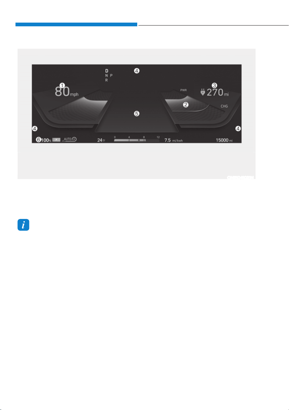
4-4
Instrument Cluster
1. Speedometer
2. Power/Charge gauge
3. Distance to empty
4. Warning indicator light
5. LCD display
6. Battery SOC (State of Charge) gauge
INSTRUMENT CLUSTER
The actual cluster in the vehicle may differ from the illustration.
For more information, refer to “Gauges and meters” section in this chapter.
ONE1041021N
Information
ś SNOW/NORMAL/ECO/SPORT mode by pressing the drive mode button will change
the main theme of the cluster
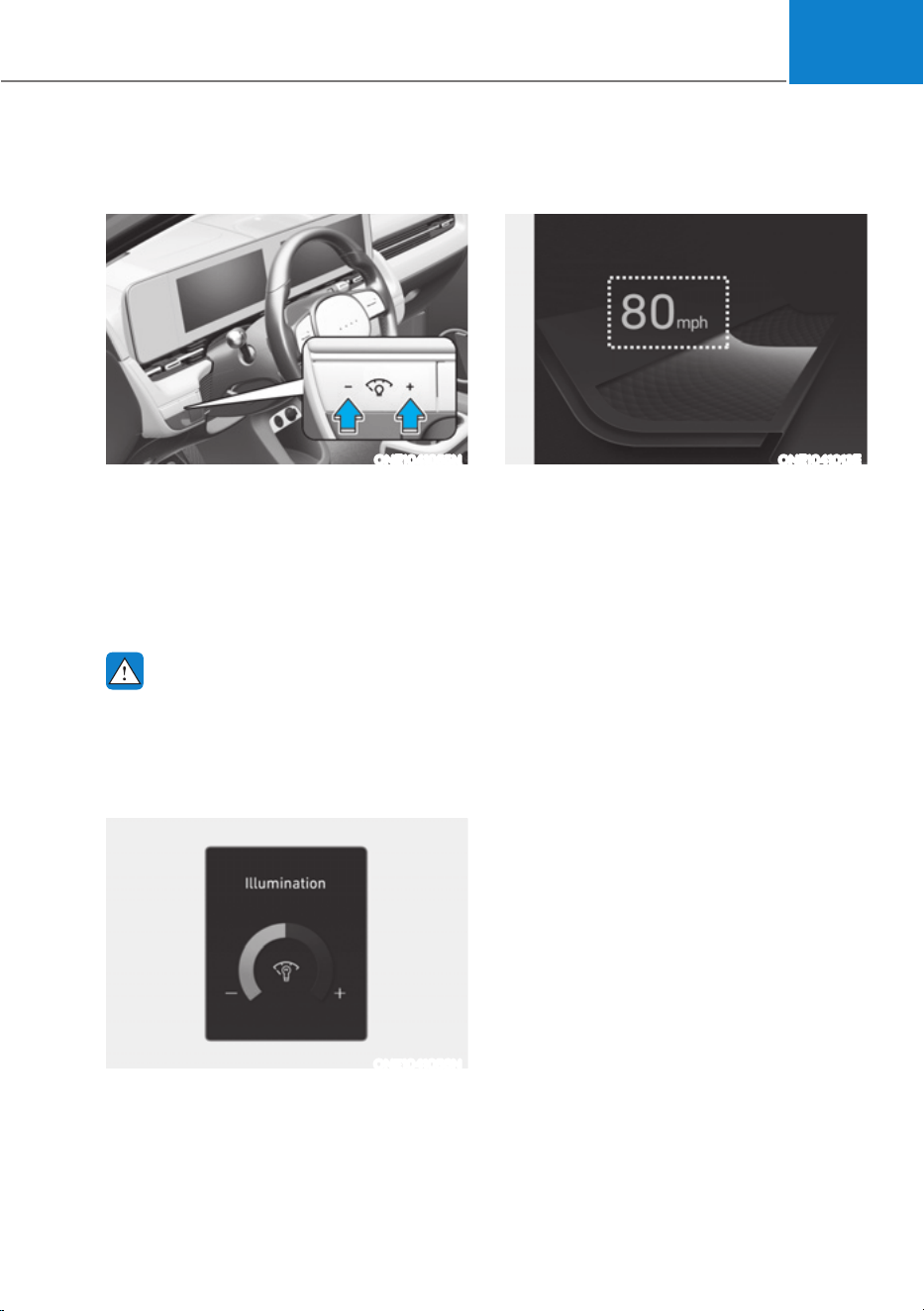
04
4-5
Instrument Cluster Control
Instrument panel illumination
ONE1041055N
When the vehicle’s position lights or
headlamps are on, press the illumination
control switch to adjust the brightness of
the instrument panel illumination.
When pressing the illumination control
switch, the interior switch illumination
intensity is also adjusted.
WARNING
Never adjust the instrument cluster
while driving. This could result in loss
of control and lead to an accident that
may cause death, serious injury, or
vehicle damage.
ONE1041056N
ś The brightness of the instrument
panel illumination is displayed.
ś If the brightness reaches to the
maximum or minimum level, a chime
will sound.
Gauges and Meters
Speedometer
ONE1041013E
The speedometer indicates the speed of
the vehicle and is calibrated in miles per
hour (MPH).
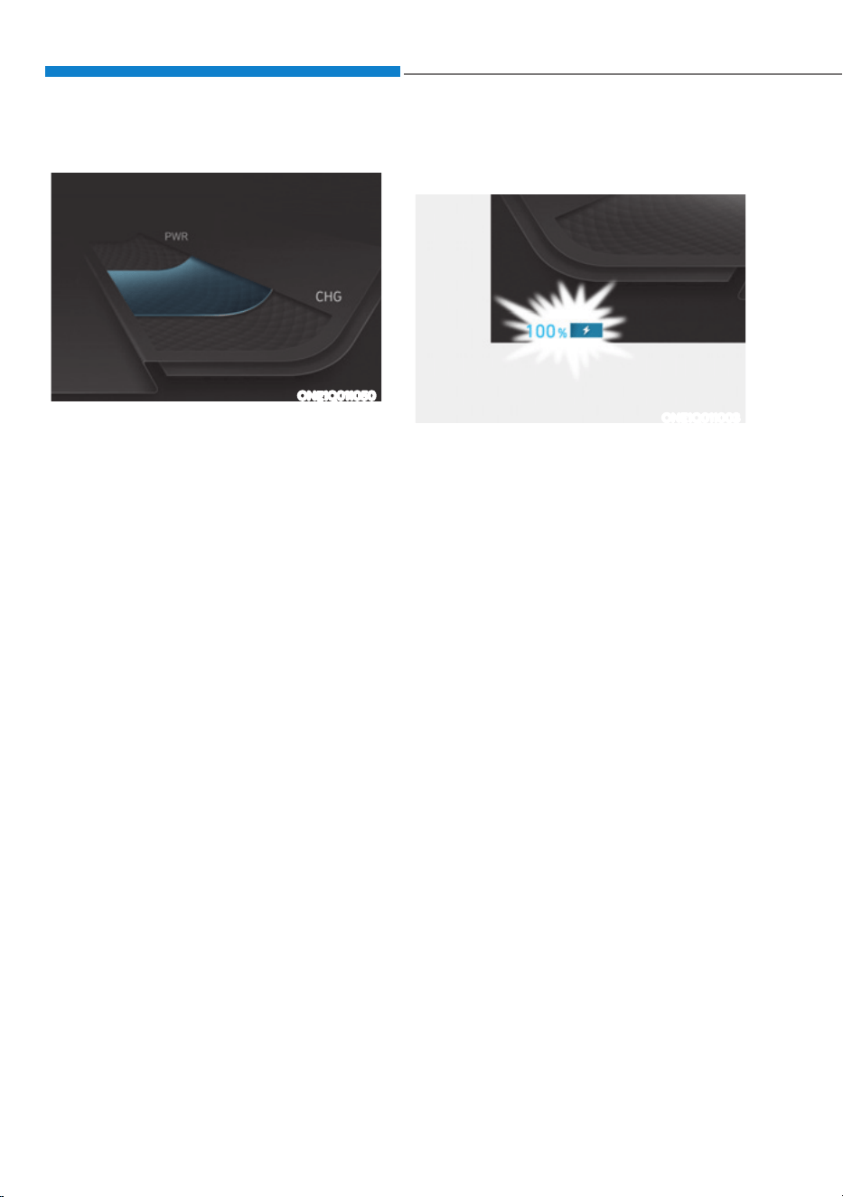
Instrument Cluster
4-6
Power/Charge Gauge
ONE1Q011050
The Power/Charge Gauge shows the
energy consumption rate of the vehicle
and the charge/discharge status of the
regenerative brakes.
ś POWER :
It shows the energy consumption rate
of the vehicle when driving uphill or
accelerating. The more electric energy
is used, the higher the gauge level.
ś CHARGE :
It shows the charging status of the
battery when it is being charged by
the regenerative brakes (decelerating
or driving on a downhill road). The
more electric energy is charged, the
lower the gauge level.
State of Charge (SOC) Gauge for
High Voltage Battery
ONE1Q011003
ś The SOC gauge shows the charging
status of the high voltage battery.
ś The low percentage number on the
indicator indicates that there is not
enough energy in the high voltage
battery. 100% indicates that the
driving battery is fully charged.
ś When driving on highways or
motorways, make sure to check
in advance if the driving battery is
charged enough.

04
4-7
ONE1Q011011
When the remaining battery is lower than
10 % on the SOC gauge, the warning light
(
) turns ON to alert you of the battery
level.
When the warning light ( ) turns ON,
the vehicle can drive an additional 18 ~
25 miles (30 ~ 40 km) depending on the
driving speed, heater/air conditioner,
weather, driving style, and other factors.
Charging is required.
NOTICE
The output is limited as the remaining
battery is low.
When the Power Down Indicator Light
is on, the vehicle may be limited to
a certain speed, it may be difficult
to climb hills, or the vehicle may be
pushed back, so charge it immediately.
Outside temperature gauge
ONE1041014N
This gauge indicates the current outside
air temperatures by 1°F (1°C).
Note that the temperature indicated
on the LCD display may not change
as quickly as the outside temperature
(there may be a slight delay before the
temperature changes.)
You can change the temperature
unit from the Settings menu in the
infotainment system screen. Select:
- *HQHUDO6HWWLQJVƟ8QLWƟ7HPSHUDWXUH
8QLWƟr&r)
For detailed information, refer to the
separately supplied infotainment
system manual.
Both the temperature unit on the cluster
LCD display and climate control screen
will change.
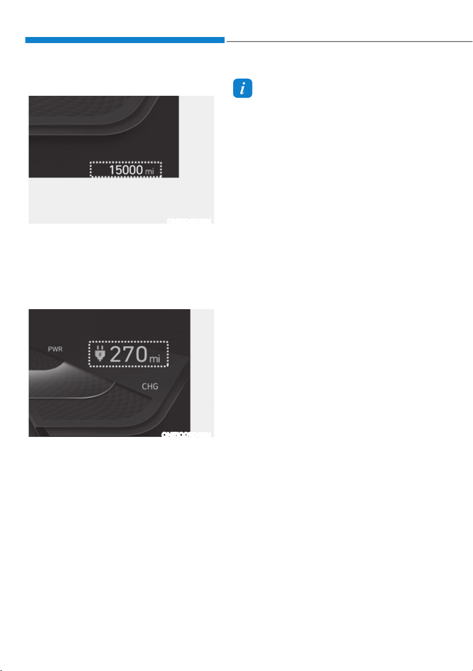
Instrument Cluster
4-8
Odometer
ONE1041016N
The odometer indicates the total
distance that the vehicle has been
driven and should be used to determine
when periodic maintenance should be
performed.
Distance to empty
ONE1Q011049N
ś The distance to empty is the
estimated distance the vehicle can
be driven with the remaining electric
energy.
ś The distance to empty varies depend
on which drive mode is selected
among ECO/NORMAL/SPORT mode.
For more detail information, refer to
‘Distance to empty’ in chapter 1.
Information
ś If the vehicle is not on level ground or
the battery power has been interrupted,
the distance to empty function may not
operate correctly.
ś The distance to empty may differ
from the actual driving distance as it
is an estimate of the available driving
distance.
ś The distance to empty may vary
significantly based on driving
conditions, driving habits, and
condition of the vehicle.
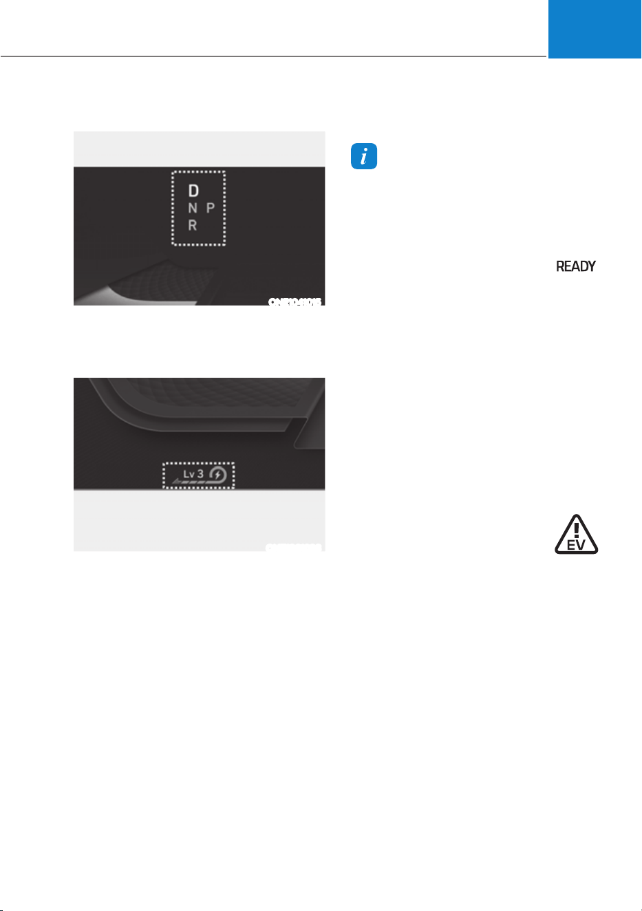
04
4-9
Reduction Gear Shift Indicator
ONE1041015
The indicator displays which gear is
selected.
Regenerative braking level indicator
ONE1061036
The regenerative brake indicates the
level of the regenerative braking that
you set. And it also indicates Smart
regenerative system’s operation status.
For more details, refer to "Regenerative
Braking System" in chapter 6.
Warning and Indicator Lights
Information
Make sure that all warning lights are OFF
after starting the vehicle. If any light is
still ON, this indicates a situation that
needs attention.
Ready indicator
This indicator illuminates:
When the vehicle is ready to be driven.
- ON : Normal driving is possible.
- OFF : Normal driving is not possible,
or a problem has occurred.
- Blinking : Emergency driving.
When the ready indicator goes OFF
or blinks, there is a problem with the
system. In this case, have your vehicle
inspected by an authorized HYUNDAI
dealer.
Service warning light
This warning light illuminates:
ś When the START/STOP button is in the
ON position.
- It illuminates for approximately 3
seconds and then goes off.
ś When there is a problem with related
parts of the electric vehicle control
system, such as sensors, etc.
When the warning light illuminates while
driving, or does not go OFF after starting
the vehicle, have your vehicle inspected
by an authorized HYUNDAI dealer.
Instrument Cluster
4-10
Power down indicator light
This indicator light illuminates:
ś When the START/STOP button is in the
ON position.
- It illuminates for approximately 3
seconds and then goes off.
ś When the power is limited for the
safety of the high-powered parts of an
electric vehicle. The power is limited
for the following reasons.(Unless both
Service Warning Light and Power
Down Indicator Light illuminate at the
same time, it is not a failure.)
- The high voltage battery level is too
low or voltage is decreasing
- The temperature of the high voltage
battery is too high or too low
- The temperature of the motor is
high
NOTICE
ś Do not accelerate or start the vehicle
suddenly when the power down
indicator light is ON.
ś When the power is limited for the
safety of the high-powered parts of
an electric vehicle, the power down
indicator light illuminates. Your
vehicle may not be driven, or may roll
back on a slope with the indicator
light ON due to the limitation of
vehicle power.
Charging connector
indicator light
This warning light indicates the
connection status of the charging
connector. When the charging connector
is connected to the vehicle, the green
light illuminates for approximately 1
minute.
High voltage battery level
warning light
This warning light illuminates:
ś When the high voltage battery level
is low.
ś When the warning light turns ON,
charge the battery immediately.
Seat belt warning light
This warning light informs the driver that
the seat belt is not fastened.
For more details, refer to “Seat Belts”
section in chapter 3.

04
4-11
Air bag warning light
This warning light illuminates:
ś When you set the Start/Stop button to
the ON position.
- The air bag warning light illuminates
for about 6 seconds and then turns
off when all checks have been
performed.
ś The air bag warning light will remain
illuminated if there is a malfunction
with the Safety Restraint System (SRS)
air bag operation.
If this occurs, have the vehicle
inspected by an authorized HYUNDAI
dealer.
Regenerative brake warning
light
This warning light illuminates:
When the regenerative brake does not
operate and the brake does not perform
well. This causes the Brake Warning
light (red) and Regenerative Brake
Warning Light (yellow) to illuminate
simultaneously.
In this case, drive safely and have your
vehicle inspected by an authorized
HYUNDAI dealer.
The operation of the brake pedal may
be more difficult than normal and the
braking distance can increase.
Parking brake & brake fluid
warning light
This warning light illuminates:
ś When you set the START/STOP button
in the ON position.
- It illuminates for approximately 3
seconds.
- It remains on if the parking brake is
applied.
ś When the parking brake is applied.
ś When the brake fluid level in the
reservoir is low.
- If the warning light illuminates
with the parking brake released, it
indicates the brake fluid level in the
reservoir is low.
ś When the regenerative brake does not
operate.
If the brake fluid level in the reservoir is
low:
1. Drive carefully to the nearest safe
location and stop your vehicle.
2. With the motor stopped, check the
brake fluid level immediately and add
fluid as required (For more details,
refer to “Brake Fluid” section in
chapter 9). After adding brake fluid,
check all brake components for fluid
leaks. If a brake fluid leak is found, or
if the warning light remains on, or if
the brakes do not operate properly, do
not drive the vehicle. Have the vehicle
inspected by an authorized HYUNDAI
dealer.
Instrument Cluster
4-12
Dual-diagonal braking system
Your vehicle is equipped with dual-
diagonal braking system. This means you
still have braking on two wheels even if
one of the dual systems should fail.
With only one of the dual systems
working, more than normal pedal travel
and greater pedal pressure is required to
stop the vehicle.
Also, the vehicle will not stop in as short
a distance with only a portion of the
brake system working.
If the brakes fail while you are driving,
shift to a lower gear for additional vehicle
braking and stop the vehicle as soon as it
is safe to do so.
WARNING
Parking Brake & Brake Fluid warning
light
Driving the vehicle with a warning light
ON is dangerous. If the Parking Brake
& Brake Fluid warning light illuminates
with the parking brake released, it
indicates that the brake fluid level is
low.
If this occurs, have the vehicle
inspected by an authorized HYUNDAI
dealer.
Anti-lock Brake System (ABS)
warning light
This warning light illuminates:
ś When you set the Start/Stop button to
the ON position.
- The ABS warning light illuminates
for about 3 seconds and then goes
off.
ś Whenever there is a malfunction with
the ABS.
Note that the hydraulic braking
system will still be operational even if
there is a malfunction with the ABS.
If this occurs, have the vehicle
inspected by an authorized HYUNDAI
dealer.
Electronic Brake Force
Distribution (EBD) system
warning light
When the ABS warning and
Parking Brake warning lights are on
simultaneously, it may indicate a
problem with the Electronic Brake Force
Distribution system.
If this occurs, have the vehicle inspected
by an authorized HYUNDAI dealer.

04
4-13
WARNING
Electronic Brake Force Distribution
(EBD) system warning light
When both ABS and Parking Brake &
Brake Fluid warning lights are on, the
brake system will not work normally
and you may experience an unexpected
and dangerous situation during sudden
braking.
If this occurs, avoid high speed driving
and abrupt braking.
Have the vehicle inspected by an
authorized HYUNDAI dealer as soon as
possible.
NOTICE
Electronic Brake Force Distribution
(EBD) system warning light
When the ABS warning light is on
or both ABS and Parking Brake &
Brake Fluid warning lights are on, the
speedometer, odometer, or tripmeter
may not work. Also, the EPS warning
light may illuminate and the steering
effort may increase or decrease.
If this occurs, have the vehicle
inspected by an authorized HYUNDAI
dealer as soon as possible.
Electric Power Steering (EPS)
warning light
This warning light illuminates:
ś When you set the Start/Stop button to
the ON position.
- The electric powering steering
warning light illuminates for about 3
seconds and then goes off.
ś Whenever there is a malfunction with
the electric power steering.
If this occurs, have the vehicle
inspected by an authorized HYUNDAI
dealer.
Master warning light
This warning light illuminates:
When there is a malfunction in operation
in any of the following systems:
- Forward Collision-Avoidance Assist
malfunction (if equipped)
- Forward Collision-Avoidance Assist
radar blocked (if equipped)
- Blind-Spot Collision Warning
malfunction (if equipped)
- Blind-Spot Collision Warning radar
blocked (if equipped)
- LED headlamp malfunction
(if equipped)
- High Beam Assist malfunction
(if equipped)
- Smart Cruise Control malfunction (if
equipped)
- Smart Cruise Control radar blocked (if
equipped)
- Tire Pressure Monitoring System
(TPMS) malfunction
To identify the details of the warning,
look at the LCD display.

Instrument Cluster
4-14
Electronic Parking Brake
(EPB) warning light
This warning light illuminates:
ś When you set the Start/Stop button to
the ON position.
- The EPB warning light illuminates
for about 3 seconds and then goes
off.
ś Whenever there is a malfunction with
EPB.
If this occurs, have the vehicle
inspected by an authorized HYUNDAI
dealer.
Information
The Electronic Parking Brake (EPB)
warning light may illuminate when
the Electronic Stability Control (ESC)
indicator light comes on to indicate that
ESC is not working properly. This does
not indicate malfunction of EPB.
Low tire pressure warning
light
This warning light illuminates:
ś When you set the Start/Stop button to
the ON position.
- The low tire pressure warning light
illuminates for approximately 3
seconds and then goes off.
ś When one or more of your tires are
significantly underinflated. (The
location of the underinflated tires are
displayed on the LCD display.)
For more details, refer to “Tire Pressure
Monitoring System (TPMS)” section in
chapter 8.
This warning light remains ON after
blinking for approximately 60 seconds, or
repeatedly blinks ON and OFF in 3 second
intervals:
When there is a malfunction with the
TPMS.
If this occurs, have the vehicle inspected
by an authorized HYUNDAI dealer as
soon as possible.
For more details, refer to “Tire Pressure
Monitoring System (TPMS)” section in
chapter 8.
04
4-15
WARNING
Safe Stopping
ś The TPMS cannot alert you to severe
and sudden tire damage caused by
external factors.
ś If you notice any vehicle instability,
immediately take your foot off the
accelerator pedal, apply the brakes
gradually with light force, and slowly
move to a safe position off the road.
Forward safety warning light
(if equipped)
This warning light illuminates:
ś When you set the Start/Stop button to
the ON position.
- The Forward Safety warning light
illuminates for approximately 3
seconds and then goes off.
ś Whenever there is a malfunction with
Forward Collision-Avoidance Assist.
If this occurs, have the vehicle inspected
by an authorized HYUNDAI dealer.
For more details, refer to “Forward
Collision-Avoidance Assist (FCA)”
section in chapter 7.
Lane safety indicator light
(if equipped)
This indicator light illuminates:
ś [Green] When Lane Keeping Assist
operating conditions are satisfied.
ś [White] When Lane Keeping Assist
operating conditions are not satisfied.
ś [Yellow] Whenever there is a
malfunction with Lane Keeping Assist.
If this occurs, have the vehicle
inspected by an authorized HYUNDAI
dealer.
For more details, refer to “Lane Keeping
Assist (LKA)” section in chapter 7.
All Wheel Drive (AWD)
warning light (if equipped)
This warning light illuminates:
Whenever there is a malfunction with the
AWD system.
If this occurs frequently, have the vehicle
inspected by an authorized HYUNDAI
dealer.
For more details, refer to "All Wheel
Drive (AWD)" section in chapter 6.

Instrument Cluster
4-16
LED headlight warning light
(if equipped)
This warning light illuminates:
ś When you set the Start/Stop button to
the ON position.
- The LED headlight warning light
illuminates for approximately 3
seconds and then goes off.
ś Whenever there is a malfunction with
the LED headlight.
If this occurs, have the vehicle
inspected by an authorized HYUNDAI
dealer.
This warning light blinks:
Whenever there is a malfunction with a
LED headlight related part.
If this occurs, have the vehicle inspected
by an authorized HYUNDAI dealer.
NOTICE
Continuous driving with the LED
Headlight warning light on or blinking
can reduce LED headlight life.
Icy road warning light
(if equipped)
This warning light is to warn the driver
the road may be icy.
When the temperature on the outside
temperature gauge is approximately
below 4°C (40°F), the Icy Road warning
light and Outside Temperature Gauge
blinks and then illuminates. Also, the
warning chime sounds 1 time.
You can activate or deactivate Icy Road
Warning function from the Settings
menu in the infotainment system screen.
Select:
- 6HWXSƟ9HKLFOH6HWWLQJVƟ&OXVWHUƟ
&RQWHQW6HOHFWLRQƟ,F\5RDG:DUQLQJ
For detailed information, refer to the
separately supplied infotainment
system manual.
Information
If the Icy Road warning light appears
while driving, you should drive more
attentively and safely refraining from
over-speeding, rapid acceleration, sudden
braking or sharp turning, etc.

04
4-17
Electronic Stability Control
(ESC) indicator light
This indicator light illuminates:
ś When you set the Start/Stop button to
the ON position.
- The Electronic Stability Control
indicator light illuminates for about
3 seconds and then goes off.
ś Whenever there is a malfunction with
ESC system.
If this occurs, have the vehicle
inspected by an authorized HYUNDAI
dealer.
This indicator light blinks:
While ESC is operating.
For more details, refer to “Electronic
Stability Control (ESC)” section in
chapter 6.
Electronic Stability Control
(ESC) OFF indicator light
This indicator light illuminates:
ś When you set the Start/Stop button to
the ON position.
- The ESC OFF indicator light
illuminates for approximately 3
seconds and then goes off.
ś When you deactivate ESC system by
pressing the ESC OFF button.
For more details, refer to “Electronic
Stability Control (ESC)” section in
chapter 6.
Immobilizer indicator light
This indicator light illuminates for up to
30 seconds:
When the vehicle detects the smart key
in the vehicle with the Start/Stop button
in the ACC or ON position.
- Once the smart key is detected, you
can start the vehicle.
- The indicator light goes off after
starting the vehicle.
This indicator light blinks for a few
seconds:
When the smart key is not in the vehicle.
- If the smart key is not detected, you
cannot start the vehicle.
This indicator light illuminates for 2
seconds and goes off:
If the smart key is in the vehicle and the
Start/Stop button is ON, but the vehicle
cannot detect the smart key.
If this occurs, have the vehicle inspected
by an authorized HYUNDAI dealer.
This indicator light blinks:
Whenever there is a malfunction with the
immobilizer system.
If this occurs, have the vehicle inspected
by an authorized HYUNDAI dealer.

Instrument Cluster
4-18
Turn signal indicator light
This indicator light blinks:
When you operate the turn signal
indicator stalk.
If any of the following occur, there may
be a malfunction with the turn signal
system.
- The turn signal indicator light
illuminates but does not blink
- The turn signal indicator light blinks
rapidly
- The turn signal indicator light does not
illuminate at all
If any of these conditions occur, have
the vehicle inspected by an authorized
HYUNDAI dealer.
High beam indicator light
This indicator light illuminates:
ś When the headlamps are on and in
the high beam position
ś When the turn signal lever is pulled
into the Flash-to-Pass position.
Light ON indicator light
This indicator light illuminates:
When the Parking lamps or headlamps
are on.
04
4-19
High Beam Assist indicator
light (if equipped)
This indicator light illuminates:
When the high-beam is on with the light
switch in the AUTO position.
ś White : When High Beam Assist is
ready to operate.
ś Green : When High Beam Assist is
operating.
If your vehicle detects oncoming or
preceding vehicles, High Beam Assist
will switch the high beam to low beam
automatically.
For more details, refer to “High Beam
Assist (HBA)” section in chapter 5.
AUTO HOLD indicator light
This indicator light illuminates:
ś [White] When you activate Auto Hold
by pressing the AUTO HOLD switch.
ś [Green] When you stop the vehicle
completely by depressing the brake
pedal with Auto Hold activated.
ś [Yellow] Whenever there is a
malfunction with the Auto Hold
function.
If this occurs, have the vehicle
inspected by an authorized HYUNDAI
dealer.
For more details, refer to “Electronic
Parking Brake (EPB)” section in chapter
6.
LCD Display Messages
Shift to P
This message is displayed if you try to
turn off the vehicle without the gear in
the P (Park) position.
If this occurs, the Start/Stop button turns
to the ACC position.
Low key battery
This message is displayed if the battery
of the smart key is discharged while
changing the Start/Stop button to the
OFF position.
Press START button while turning
wheel (if equipped)
This message is displayed if the steering
wheel does not unlock normally when
the Start/Stop button is pressed.
You should press the Start/Stop button
while turning the steering wheel right
and left.
Press brake pedal to start vehicle
This message is displayed if the Start/
Stop button changes to the ACC position
twice by pressing the button repeatedly
without depressing the brake pedal.
You can start the vehicle by depressing
the brake pedal and then pressing the
Start/Stop button.

Instrument Cluster
4-20
Key not in vehicle
This message is displayed if the smart
key is not in the vehicle when you leave
the vehicle with the Start/Stop button in
the ON or Start position.
Always turn off the vehicle before leaving
your vehicle.
Key not detected
This message is displayed if the smart
key is not detected when you press the
Start/Stop button.
Press START button again
This message is displayed if you were
unable to start the vehicle when the
Start/Stop button was pressed.
If this occurs, attempt to start the vehicle
by pressing the Start/ Stop button again.
If the warning message appears each
time you press the Start/Stop button,
have the vehicle inspected by an
authorized HYUNDAI dealer.
Press START button with key
This message is displayed if you press
the Start/Stop button while the warning
message “Key not detected” is displayed.
At this time, the immobilizer indicator
light blinks.
Check BRAKE SWITCH fuse
This message is displayed if the brake
switch fuse is disconnected.
You need to replace the fuse with a new
one before starting the vehicle.
If that is not possible, you can start the
vehicle by pressing the Start/Stop button
for 10 seconds in the ACC position.
Shift to P or N to start vehicle
This message is displayed if you try to
start the vehicle in any other position
except P (Park) or N (Neutral).
Information
You can start the vehicle with the gear in
N (Neutral). But, for your safety, start the
vehicle with the gear shifted to P (Park).
Check smart key system
This message is displayed when there is a
problem with the smart key system. Have
the vehicle inspected by an authorized
HYUNDAI dealer.
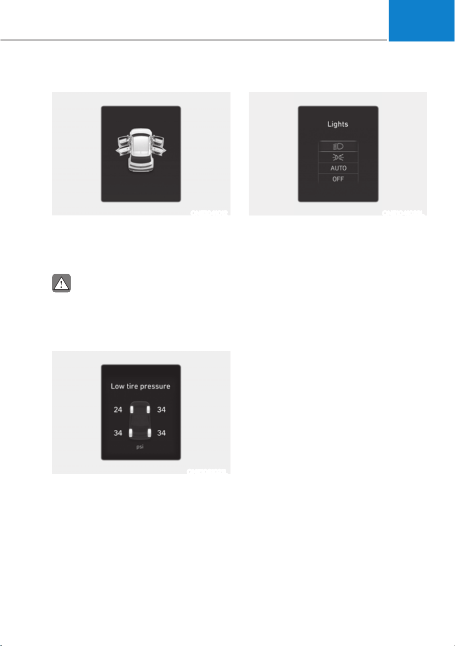
04
4-21
Door, Hood, Liftgate open indicator
ONE1041012
This warning is displayed if any door or
hood or liftgate is left open. The warning
will indicate which door is open in the
display.
CAUTION
Before driving the vehicle, you should
confirm that the door/ hood/liftgate are
fully closed.
Low tire pressure
ONE1081021L
This warning message is displayed if the
tire pressure is low. The corresponding
tire on the vehicle will be illuminated.
For more details, refer to “Tire Pressure
Monitoring System (TPMS)” section in
chapter 8.
Lights
ONE1041032L
This indicator displays which exterior
light is selected using the lighting
control.
You can activate or deactivate Wiper/
Lights display function from the Settings
menu in the infotainment system screen.
Select:
- 6HWXSƟ9HKLFOH6HWWLQJVƟ&OXVWHU
Ɵ&RQWHQW6HOHFWLRQƟ:LSHU/LJKWV
Display
For detailed information, refer to the
separately supplied infotainment
system manual.

Instrument Cluster
4-22
Wiper
ONE1041004L
This indicator displays which wiper speed
is selected using the wiper control.
You can activate or deactivate Wiper/
Lights display function from the Settings
menu in the infotainment system screen.
Select:
- 6HWXSƟ9HKLFOH6HWWLQJVƟ&OXVWHU
Ɵ&RQWHQW6HOHFWLRQƟ:LSHU/LJKWV
Display
For detailed information, refer to the
separately supplied infotainment
system manual.
Low washer fluid (if equipped)
This message is displayed if the washer
fluid level in the reservoir is nearly empty.
Have the washer fluid reservoir refilled.
Check headlight (if equipped)
This message is displayed if the
headlights are not operating properly. A
lamp may need to be replaced.
Make sure to replace the burned out
bulb with a new one of the same wattage
rating.
Check turn signal (if equipped)
This message is displayed if the turn
signal lamps are not operating properly.
A lamp may need to be replaced.
Make sure to replace the burned out
bulb with a new one of the same wattage
rating.
Check headlamp LED (if equipped)
This message is displayed if there is a
problem with the LED headlamp. Have
the vehicle inspected by an authorized
HYUNDAI dealer.
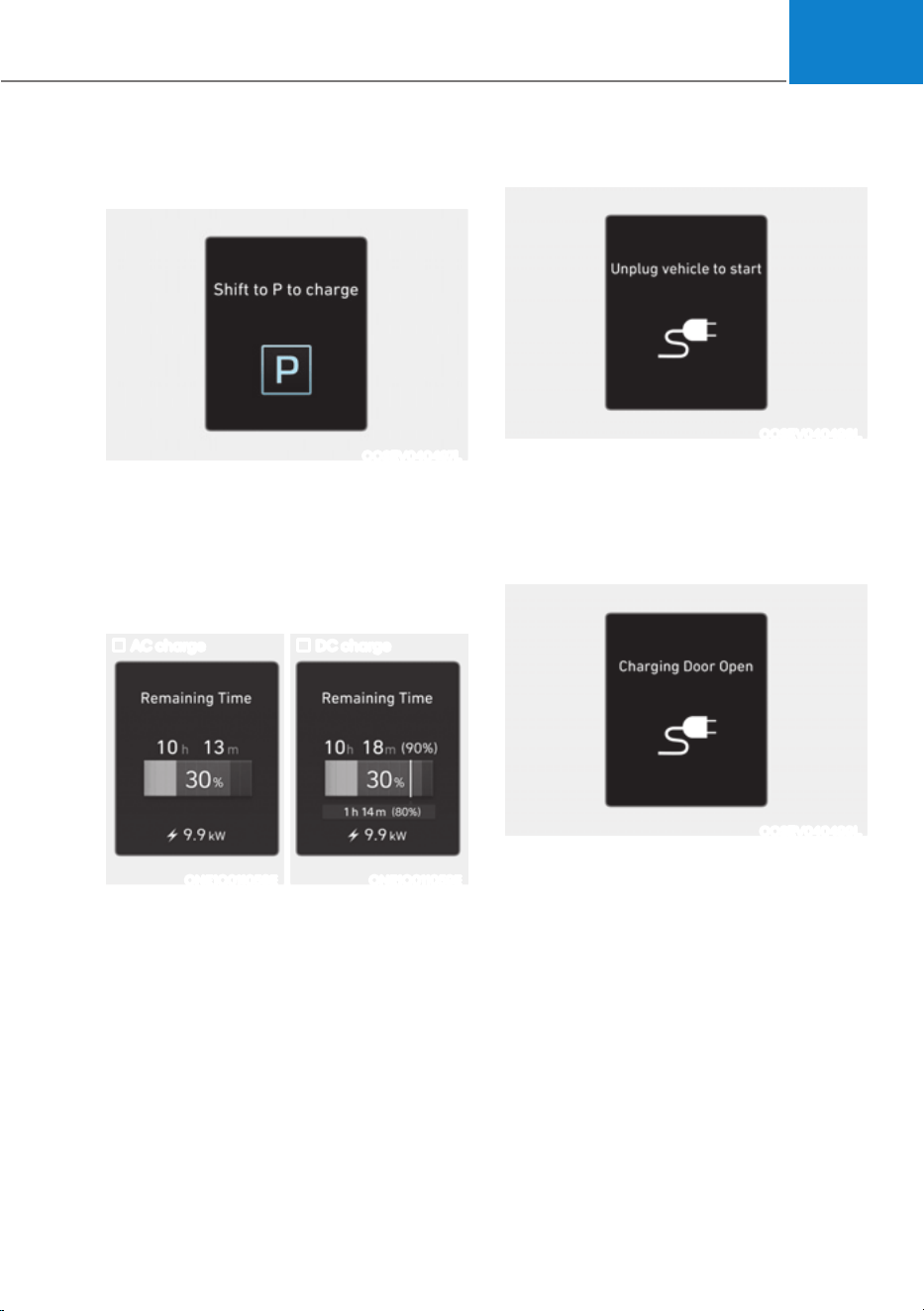
04
4-23
Shift to P to charge/Shift to P to
start charging
OOSEV040497L
This message is displayed if you connect
the charging cable without the gear in
the P (Park) position.
Shift to P (Park) before connecting the
charging cable.
Remaining time
AC charge DC charge
ONE1Q011058E ONE1Q011059E
This message is displayed to notify the
remaining time to charge the battery to
the selected target battery charge level.
Unplug vehicle to start
OOSEV040498L
This message is displayed when you
start the vehicle without unplugging the
charging cable. Unplug the charging
cable, and then turn on the vehicle.
Charging door open
OOSEV040499L
This message is displayed when the
vehicle is driven with the charging door
opened. Close the charging door and
then start driving.
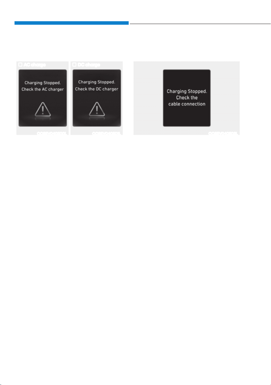
Instrument Cluster
4-24
Charging stopped. Check the AC/DC
charger
AC charge DC charge
OOSEV040500L OOSEV040501L
ś This warning message is displayed
when charging is stopped for the
reasons below:
- There is a problem with the external
AC charger or DC charger charger
- The external AC charger stopped
charging
- The charging cable is damaged
In this case, check whether there is any
problem with the external AC or DC
charger and charging cable.
If the same problem occurs when
charging the vehicle with a normally
operating AC charger or genuine
HYUNDAI portable charger, have your
vehicle inspected by an authorized
HYUNDAI dealer.
Charging stopped. Check the cable
connection
OOSEV040502L
This warning message is displayed
when charging is stopped because the
charging connector is not correctly
connected to the charging inlet
In this case, separate the charging
connector and re-connect it and check
whether there is any problem (external
damage, foreign substances, etc.) with
the charging connector and charging
inlet.
If the same problem occurs when
charging the vehicle with a replaced
charging cable or genuine HYUNDAI
portable charger, have your vehicle
inspected by an authorized HYUNDAI
dealer.
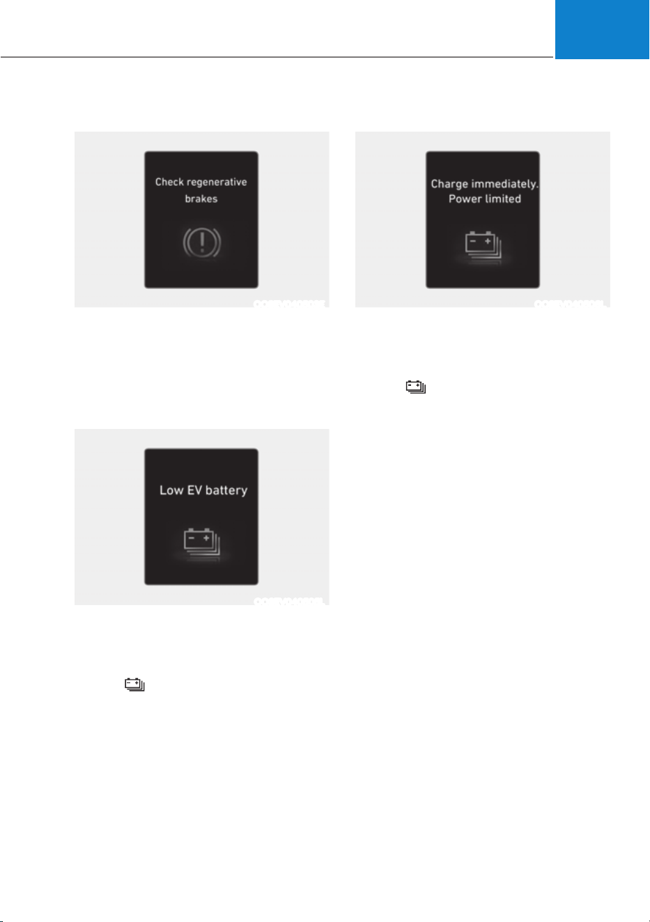
04
4-25
Check regenerative brakes
OOSEV040503E
These warning messages are displayed
when the regenerative brake system
does not work properly.
In this case, have the vehicle inspected
by an authorized HYUNDAI dealer.
Low EV battery
OOSEV040505L
When the high voltage battery level
reaches below approximately 10 %, this
warning message is displayed.
The warning light on the instrument
cluster (
) will turn ON simultaneously.
Charge the high voltage battery
immediately.
Charge immediately. Power limited
OOSEV040506L
When the high voltage battery level
reaches below approximately 5 %, this
warning message is displayed.
The warning light on the instrument
cluster (
) will turn on simultaneously.
The vehicle’s power will be reduced to
minimize the energy consumption of the
high voltage battery. Charge the battery
immediately.

Instrument Cluster
4-26
12V battery discharging due to
additional electrical devices
ONE1041054L
This warning message is displayed when
a battery discharge due to excessive
current is detected by mounting an
unauthorized electrical device such as a
black box.
Be careful as it may cause battery
discharge problems.
If the warning message is not
disappeared after the external electrical
device is removed, have the vehicle
inspected by an authorized HYUNDAI
dealer.
Power limited due to low EV battery
temperature. Charge battery
OOSEV040507L
Both warning messages are displayed
to protect electric vehicle system when
outside temperature is low. If the high
voltage battery charging level is low
and parked outside in low temperature
for a long time, vehicle power could be
limited.
Charging the battery before driving helps
increase power.
NOTICE
If these warning messages are still
displayed even after the ambient
temperature has increased, have the
vehicle inspected by an authorized
HYUNDAI dealer.

04
4-27
EV battery overheated! Stop vehicle
OOSEV040509L
This warning message is displayed to
protect battery and electric vehicle
system when the high voltage battery
temperature is too high.
Turn off the START/STOP button and
stop the vehicle so that the battery
temperature decreases.
Power limited
ONE1Q011008L
This Indicator light illuminates:
ś When the START/STOP button is in
the ON position.
- It illuminates for approximately 3
seconds and then goes off.
ś When the power is limited for the
safety of the high-powered parts of an
electric vehicle. The power is limited
for the following reasons. (Unless
both Service Warning Light and Power
Down Indicator Light illuminate at the
same time, it is not a failure.)
- The high voltage battery level is too
low or voltage is decreasing
- The temperature of the high voltage
battery is too high or too low
- The temperature of the motor is
high
NOTICE
ś When this warning message is
displayed, do not accelerate or start
the vehicle suddenly.
ś When the power is limited for the
safety of the high-powered parts
of an electric vehicle, the warning
message is displayed. Your vehicle
may not be driven, or may roll back
on a slope with the warning message
displayed due to the limitation of
vehicle power.
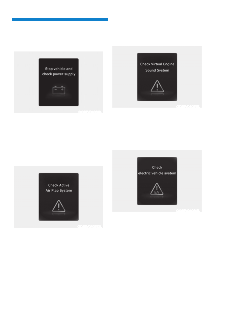
Instrument Cluster
4-28
Stop vehicle and check power
supply
OOSEV040511L
This warning message is displayed when
a failure occurs in the power supply
system.
In this case, park the vehicle in a safe
location and tow your vehicle to the
nearest authorized HYUNDAI dealer and
have the vehicle inspected.
Check active air flap system
OOSEV040510L
This warning message is displayed in the
following situations:
- There is a malfunction with the
actuator flap
- There is a malfunction with the
actuator air flap controller
- The air flap does not open
When all of the above conditions are
fixed, the warning will disappear.
Check virtual engine sound system
OOSEV040512L
This message is displayed when there is
a problem with the Virtual Engine Sound
System (VESS).
In this case, have the vehicle inspected
by an authorized HYUNDAI dealer.
Check electric vehicle system
OOSEV040513L
This warning message is displayed when
there is a problem with the electric
vehicle control system.
Refrain from driving when the warning
message is displayed.
In this case, have the vehicle inspected
by an authorized HYUNDAI dealer.
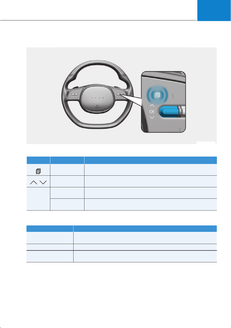
04
4-29
LCD Display Control
ONE1041018
The LCD display modes can be changed by using the control switches.
Switch Operation Function
Press MODE button for changing View modes
,
Press
UP, DOWN switch for changing items in Utility view and
Option menu
OK
Press SELECT/RESET switch for entering Option menu
Press and hold
SELECT/RESET switch for retrieving assist information or
resetting the selected item
View Modes
View modes Explanation
Driving Assist
Driving Assist view displays the status of the vehicle’s Driver
Assistance systems.
Turn by Turn Turn By Turn view displays the state of the navigation.
Utility
Utility view displays driving information such as the trip distance,
electric energy economy and etc.
The information provided may differ depending on which features are applicable to
your vehicle.
LCD DISPLAY
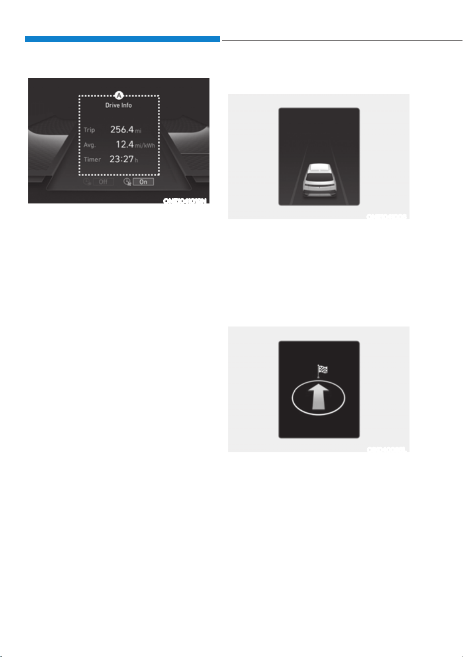
Instrument Cluster
4-30
ONE1041019N
Driving Assist, Turn by Turn, Utility view
modes are displayed in the center (A) of
the instrument cluster.
Driving Assist view
ONE1041006
The status of Manual Speed Limit Assist,
Smart Cruise Control, Lane Following
Assist, Highway Driving Assist, etc., is
displayed when Driving Assist view is
selected.
For more details, refer to each function
information section in chapter 7.
Turn By Turn (TBT) view
OIK040085L
Turn-by-turn navigation, distance/time
to destination information is displayed
when Turn by Turn view is selected.
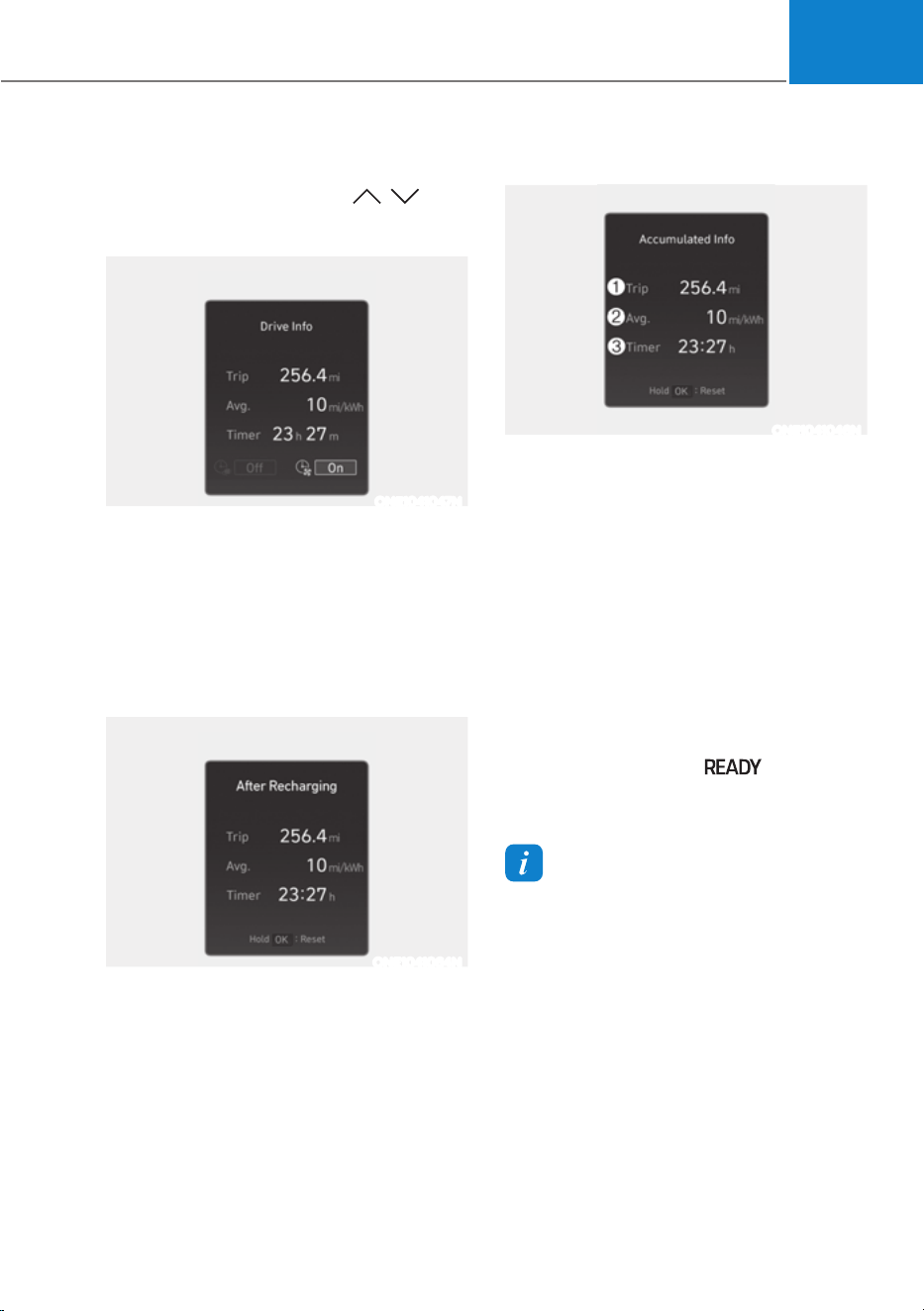
04
4-31
Utility view
In the Utility view, using the , (UP,
DOWN) switch, you may change through
items in the following order.
ONE1041047N
Drive info
Trip distance, average electric energy
economy and total driving time are
displayed.
The driver’s door is opened after turning
off the vehicle or the vehicle is turned on
after 3 minutes have passed, the Drive
Info screen will reset.
ONE1041064N
After Recharging
Trip distance, total driving time and
average energy consumption after
the vehicle has been recharged are
displayed. To reset manually, press
the OK button on the steering wheel
for more than 1 second when ‘After
recharging’ is displayed.
Accumulated info
ONE1041046N
This display shows the accumulated
trip distance (1), the average energy
consumption (2), and the total driving
time (3).
The information is accumulated starting
from the last reset.
To manually reset the information,
press and hold the OK button when
viewing the Accumulated driving info.
The trip distance, the average energy
consumption, and total driving time will
reset simultaneously.
The accumulated driving information
will continue to be counted while the
vehicle is in the ready (
) mode (for
example, when the vehicle is in traffic or
stopped at a stop light).
Information
The vehicle must be driven for a minimum
of 0.19 miles (300 meters) since the last
ignition key cycle before the accumulated
driving information is recalculated.
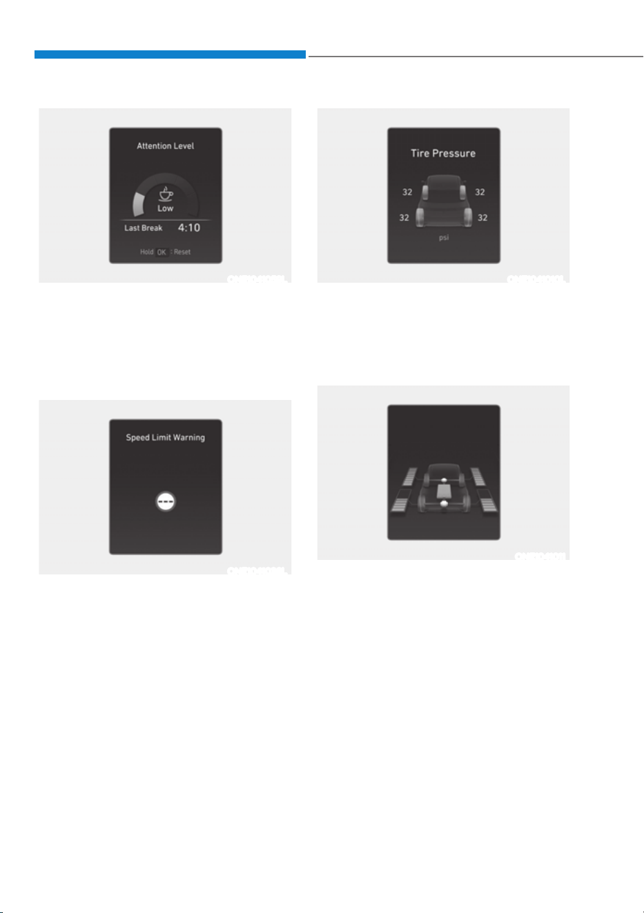
Instrument Cluster
4-32
ONE1041059L
Attention level
The driver’s attention level is shown
based on the driver’s driving pattern.
For more details, refer to "Driver
Attention Warning (DAW)“ section in
chapter 7.
ONE1041038L
Speed limit warning (if equipped)
The driver can monitor the information
provided from Intelligent Speed Limit
Assist.
For more details, refer to "Intelligent
Speed Limit Assist (ISLA)" section in
chapter 7.
ONE1041010L
Tire pressure
The tire pressure of each tire is displayed.
For more details, refer to “Tire Pressure
Monitoring System (TPMS)” section in
chapter 8.
ONE1041011
Energy flow / Driving force distribution (if
equipped)
ś The electric vehicle system informs
the drivers its energy flow in various
operating modes.
ś The distribution status of the driving
power of the front and rear wheels are
displayed when Auto AWD mode is
activated.
For more details, refer to "Four Wheel
Drive (AWD)" section in chapter 6.
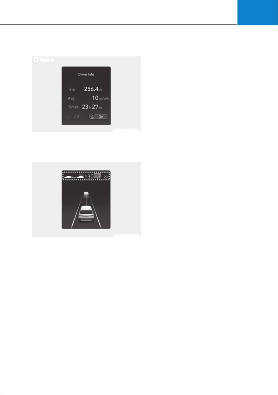
04
4-33
Additional information display
Type A
ONE1041047N
Drive info
Drive information is displayed for 4
seconds after the vehicle is turned off.
ONE1041031N
Driving assist information
The current operation conditions of
Manual Speed Limit Assist, Cruise
Control, Smart Cruise Control, Lane
Following Assist, Highway Driving Assist,
etc., is displayed.

Instrument Cluster
4-34
9(+,&/(6(77,1*6ǣ,1)27$,10(176<67(0Ǥ
Vehicle Settings in the infotainment
system provides user options for a
variety of settings including door lock/
unlock features, convenience features,
driver assistance settings, etc.
Vehicle Settings menu
- Driver Assistance
- Drive Mode
-EV
- Head-Up Display
- Cluster
- Climate
- Seat
- Lights
- Door
- Convenience
The information provided may differ
depending on which features are
applicable to your vehicle.
WARNING
Do not operate the Vehicle Settings
while driving. This may cause
distraction resulting in an accident.
Setting Your Vehicle
ONE1041051K
1. Press the Custom (★) button on the
head unit of the infotainment system.
2. Select ‘Vehicle’ and change the
setting of the features.
For detailed information, refer to the
separately supplied infotainment
system manual.

5
5. Convenience Features
Accessing Your Vehicle ..................................................................................... 5-4
Smart Key ......................................................................................................................5-4
Immobilizer System ................................................................................................... 5-14
Hyundai Digital Key ....................................................................................................5-15
Door Locks ....................................................................................................... 5-30
Operating Door Unlocks from Outside the Vehicle (Manual type) .........................5-30
Operating Door Unlocks from Outside the Vehicle (Electric type) ........................5-30
Operating Door Locks from Outside the Vehicle (Manual type) ............................. 5-32
Operating Door Locks from Outside the Vehicle (Electric type) ............................ 5-32
Operating Door Lock/Unlock from Inside the Vehicle .............................................5-34
Automatic Door Lock and Unlock Features ..............................................................5-36
Electronic Child Safety Lock ...................................................................................... 5-37
Vehicle Auto-Shut Off Function ................................................................................5-38
Theft-alarm System ........................................................................................ 5-39
Integrated memory system ............................................................................5-40
Storing Memory Positions ........................................................................................ 5-40
Recalling Memory Positions ..................................................................................... 5-40
Resetting the System ................................................................................................. 5-41
Seat Easy Access ........................................................................................................5-42
Memory Seat Configurations ......................................................................... 5-43
Storing Memory Positions .........................................................................................5-43
Recalling Memory Positions ......................................................................................5-43
Steering Wheel ................................................................................................ 5-44
Electric Power Steering (EPS) ................................................................................... 5-44
Tilt/Telescopic Steering .............................................................................................5-45
Horn............................................................................................................................ 5-46
Heated Steering Wheel ............................................................................................. 5-46
Mirrors .............................................................................................................5-48
Inside Rearview Mirror .............................................................................................. 5-48
Side View Mirrors .......................................................................................................5-59
Reverse Parking Aid ................................................................................................... 5-61
Windows .......................................................................................................... 5-63
Power Windows ......................................................................................................... 5-64
Vision Roof ...................................................................................................... 5-67
Resetting the Vision Roof ......................................................................................... 5-69

5
Exterior Features ............................................................................................. 5-70
Hood ............................................................................................................................5-70
Front trunk ...................................................................................................................5-71
Power Liftgate ............................................................................................................ 5-72
Smart Liftgate ............................................................................................................. 5-78
Electric Charging Door ....................................................................................5-81
Augmented reality HUD ................................................................................. 5-82
Head-up display Settings ..........................................................................................5-82
Head-up display Information ....................................................................................5-83
Precautions while Using the Head-up display ........................................................ 5-84
Lighting ............................................................................................................ 5-85
Exterior Lights ............................................................................................................5-85
Interior Lights ............................................................................................................ 5-89
High Beam Assist (HBA) ................................................................................5-93
High Beam Assist Settings .........................................................................................5-93
High Beam Assist Operation ..................................................................................... 5-94
High Beam Assist Malfunction and Limitations .......................................................5-95
Wipers and Washers .......................................................................................5-96
Front Windshield Wipers .......................................................................................... 5-96
Front Windshield Washers ........................................................................................ 5-98
Automatic Climate Control System ...............................................................5-99
Climate ...................................................................................................................... 5-100
Automatic Temperature Control Mode ...................................................................5-100
Manual Temperature Control Mode ........................................................................ 5-102
System Operation ......................................................................................................5-110
System Maintenance .................................................................................................5-111
Windshield Defrosting and Defogging ..........................................................5-113
To Defog Inside Windshield ...................................................................................... 5-113
To Defrost Outside Windshield ................................................................................. 5-114
Defogging Logic ........................................................................................................ 5-114
Rear Window Defroster............................................................................................. 5-115

5
Climate Control Additional Features .............................................................5-116
A/C Automatic Drying ..............................................................................................5-116
Auto Defogging System ............................................................................................ 5-117
Auto Dehumidify ....................................................................................................... 5-118
Recirculating Air When Washer Fluid Is Used ......................................................... 5-118
Auto. Controls That Use Climate Control Settings (for driver’s seat) ....................5-119
Smart ventilation ....................................................................................................... 5-119
Storage Compartment ...................................................................................5-120
Center Console Storage ........................................................................................... 5-120
Glove Box ................................................................................................................... 5-121
Interior Features ............................................................................................. 5-122
Cup Holder .................................................................................................................5-122
Sunvisor .....................................................................................................................5-123
Power Outlet ..............................................................................................................5-123
USB Charger ............................................................................................................. 5-124
Wireless Smart Phone Charging System .................................................................5-125
Cluster Fascia Side Panel ......................................................................................... 5-128
Vehicle to Load (V2L) ............................................................................................... 5-128
Clock ......................................................................................................................... 5-128
Coat Hook ................................................................................................................. 5-129
Floor Mat Anchor(s) .................................................................................................. 5-129
Rear Side Window Sunshades ................................................................................ 5-130
Luggage Net Holder ................................................................................................. 5-130
Cargo Security Screen .............................................................................................. 5-131
Infotainment System ..................................................................................... 5-133
USB Port .................................................................................................................... 5-133
Antenna ..................................................................................................................... 5-133
Steering Wheel Remote Controls ............................................................................ 5-133
Infotainment System ................................................................................................ 5-134
Voice Recognition .....................................................................................................5-135
Bluetooth® Wireless Technology ..............................................................................5-135
5. Convenience Features
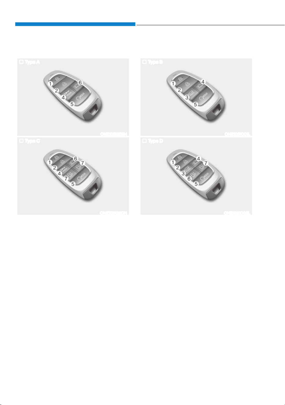
Convenience Features
5-4
Your electric vehicle uses a Smart Key, which you can use to lock or unlock the driver
and passenger doors, the charging door or the rear liftgate.
1. Door lock
2. Door unlock
3. Liftgate open/close
4. Panic
5. Remote Start
6. Charging door open/close
7. Forward / Backward (if equipped)
Smart Key
Type A
ONE1051259N
Type C
ONE1051260N
Type B
ONE1051001L
Type D
ONE1051002L
ACCESSING YOUR VEHICLE
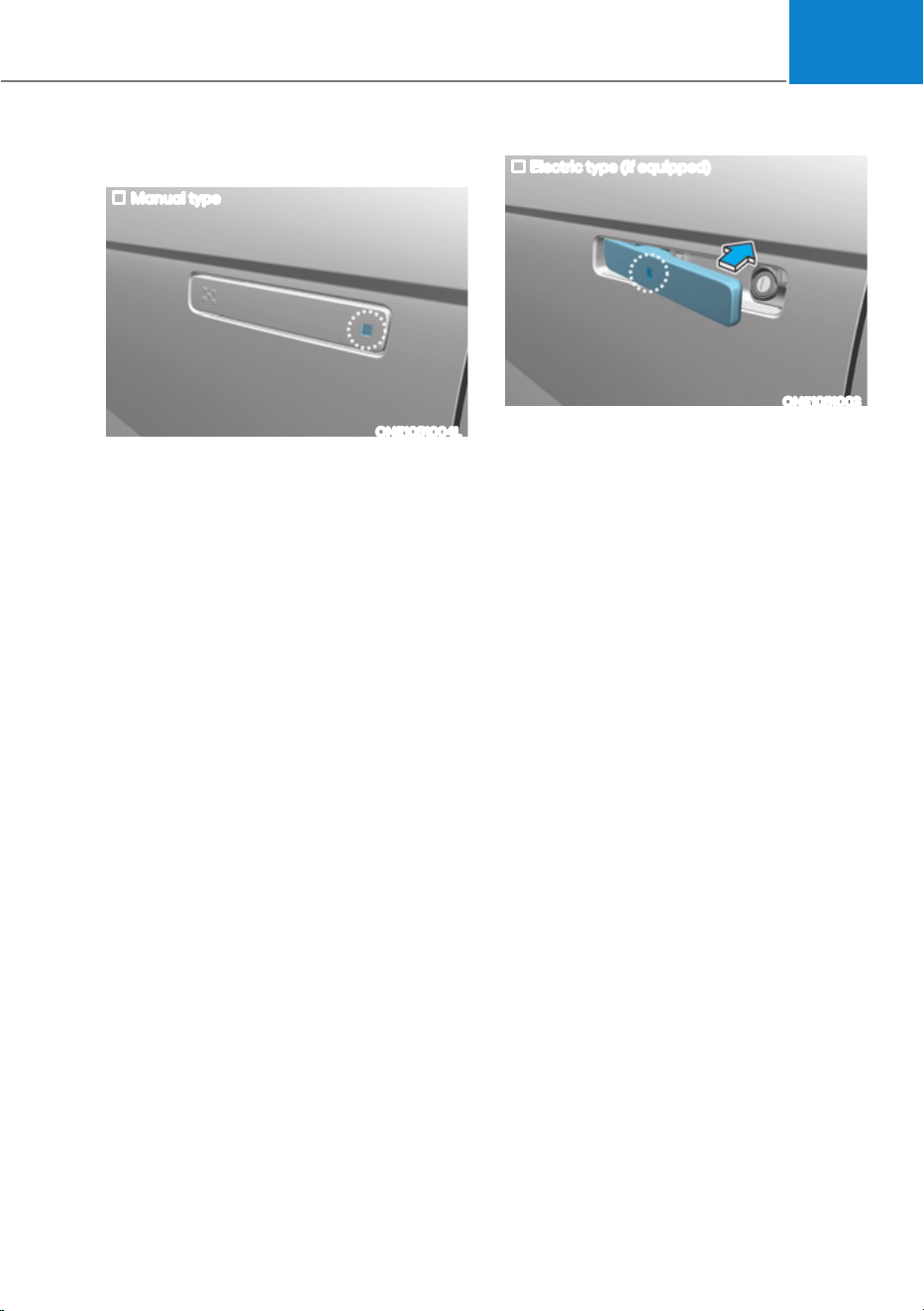
05
5-5
Locking your vehicle
Manual type
ONE1051004L
To lock your vehicle using the door
handle button or the Smart Key:
1. Make sure all doors, the hood and the
liftgate are closed.
2. Press the Door Lock button (1) on the
Smart Key. The hazard warning lights
will blink with an alarm, and the doors
will be locked.
3. In addition, pushing the button on
the door handle (the engraved part)
while keeping the smart key will lock
all doors.
Electric type (if equipped)
ONE1051003
To lock your vehicle using the door
handle touch sensor or the Smart Key:
1. Make sure all doors, the hood and the
liftgate are closed.
2. Press the Door Lock button (1) on
the Smart key. The hazard warning
lights will blink with an alarm, and the
handles will retract back.
ś In addition, touching the touch sensor
on the door handle (the engraved
part) while keeping the smart key will
lock all doors and let the door handle
to retract back.

Convenience Features
5-6
Information
ś The outside rearview mirror will
fold if ‘Enable on Door Unlock’ is
selected from the Settings menu in the
infotainment system screen. Select:
- 6HWXSĺ9HKLFOH6HWWLQJVĺ
&RQYHQLHQFHĺ:HOFRPH0LUURUĺ
Enable on Door Unlock
ś The door handle touch sensor will only
operate when the smart key is within
0.7~1 m (28~40 in.) from the outside
door handle.
ś Touching the door handle touch sensor
does not unlock the doors. To unlock
the doors, refer to the following page.
Note that you cannot lock your vehicle
using the door handle touch sensor if any
of the following occur:
ś The Smart Key is in the vehicle.
ś The Start/Stop button is in ACC or ON
position.
ś Any of the doors are open except for
the liftgate.
WARNING
Do not leave the Smart Key in your
vehicle with unsupervised children.
Unattended children could press the
Start/ Stop button and may operate
power windows or other controls, or
even make the vehicle move, which
could result in serious injury or death.
Information
ś To fold/unfold the rearview mirror
simultaneously when the door is locked/
XQORFNHGVHOHFWµ6HWWLQJVĺ9HKLFOH
ĺ&RQYHQLHQFHĺ:HOFRPH0LUURU
ĺ(QDEOHRQ'RRU8QORFN¶LQWKH
infotainment screen.
ś The door handle button will only
operate when the smart key is within
0.7~1 m (28~40 in.) from the outside
door handle. Other people can also
open the doors without the smart key in
possession.
ś After unlocking the doors, the doors
will lock automatically after 30 seconds
unless a door is opened.
For detailed information, refer to the
separately supplied infotainment system
manual.

05
5-7
Unlocking your vehicle
Manual type
ONE1051004L
To unlock your vehicle using the door
handle button or the Smart Key:
1. Make sure you have the smart key in
your possession.
2. Pushing the button on the door
handle(engraved part) or press the
Door Unlock button (2) on the smart
key. All doors handles will be unlocked
and the hazard warning lights will
blink twice.
3. After unlocking the doors, the doors
will automictically re-lock after 30
seconds unless a door is opened.
Electric type (if equipped)
ONE1051004
:KHQ\RXUHOHDVHWKH7ZR3UHVV8QORFN
function
To unlock your vehicle using the door
handle touch sensor or the Smart Key:
1. Make sure you have the smart key in
your possession.
2. Touch the touch sensor on the door
handle(engraved part) or press the
Door Unlock button (2) on the smart
key. All door handles will pop out and
the doors will be unlocked and the
hazard warning lights will blink and
the chime will sound.
3. After unlocking the doors, the doors
will automatically re-lock after 30
seconds unless a door is opened.

Convenience Features
5-8
:KHQ\RXVHWWKH7ZR3UHVV8QORFN
function
1. Make sure you have the smart key in
your possession.
2. Touch the touch sensor on the door
handle(engraved part) or press the
Door Unlock button (2) on the smart
key. The driver’s door handle will
pop out and the driver’s door will be
unlocked.
3. Touch the touch sensor on the door
handle(engraved part) or press the
Door Unlock button (2) on the smart
key within 4 seconds again. All door
handles will pop out and the doors will
be unlocked and the hazard warning
lights will blink twice and the chime
will sound.
4. After unlocking the doors, the doors
will automatically re-lock after 30
seconds unless a door is opened.
Two Press Unlock Feature
The priority for unlocking the driver door
only, or unlocking all the doors with
one press may be adjusted in the User
Settings menu in the LCD cluster display.
The Two Press Unlock feature, when
enabled, will require the user to press
the door unlock button once for driver
door only and twice for unlocking all the
doors.
Select or Deselect the Two Press Unlock
Feature in the User Settings menu in the
LCD cluster display. The option can be
found under the following menu:
86(56(77,1*6Ɵ'225Ɵ7:235(66
UNLOCK
The Two Press Unlock Feature can also
be enabled or disabled by pressing
the door lock and unlock buttons
simultaneously on the Key FOB:
Press and hold both the DOOR LOCK
button and the DOOR UNLOCK button
simultaneously until the hazard warning
lights blink.
This will enable or disable the Two Press
Unlock feature. Repeat this procedure to
enable/disable the mode again.

05
5-9
Information
ś The outside rearview mirror will
unfold if ‘Enable on Door Unlock’ is
selected from the Settings menu in the
infotainment system screen. Select:
- 6HWXSĺ9HKLFOH6HWWLQJVĺ
&RQYHQLHQFHĺ:HOFRPH0LUURUĺ
Enable on Door Unlock
ś The door handle touch sensor will only
operate when the smart key is within
0.7~1 m (28~40 in.) from the outside
door handle.
ś The doors may lock or unlock if the
touch sensor of the outer door handle is
recognized while washing your car or
due to heavy rain.
ś To prevent unintentional door lock or
unlock:
3UHVVWKHORFNEXWWRQRQWKHVPDUW
key and immediately press the unlock
button along with the lock button
for more than 4 seconds. The hazard
warning lights will blink four times.
At this time, the doors will not lock or
unlock even though the touch sensor is
touched on the outside door handle.
To deactivate the function, press the
door lock or unlock button on the
smart key.
ś The doors may not lock or unlock in
the following situations.
- If the touch sensor is touched with
gloves on
- If the door is suddenly approached
Information
During a car wash or rain, in order to
minimize unintentional operation of the
touch sensor, the touch sensor may become
insensitive. This is not a malfunction.
Opening the liftgate
To open the liftgate:
1. Make sure you have the smart key in
your possession.
2. Press the liftgate open/close button
(3) on the vehicle or press and hold
the Liftgate handle switch on the
smart key for more than one second.
The hazard warning lights will blink
two times and the liftgate will open.
Information
The liftgate open/close button will only
operate when the smart key is within 0.7
m (28 in.) from the liftgate.

Convenience Features
5-10
Remotely opening and closing the
charging door
To open charging door remotely:
Press the Charging Door Open/Close
button (4) for more than one second,
or press the charging door open/close
button in the vehicle while carrying the
smart key.
To close the charging door:
Press the Charging Door Open/Close
button (4) for more than a second while
the door is open, or press the charging
door open/close button in the vehicle
while carrying the smart key when the
charging door is opened.
Remotely initiating electricity
charging
To remotely start charging the vehicle:
Press the charging door open/close
button in the smart key while the
charging connector is connected to the
vehicle.
For more details, refer to “Charging
Electric Vehicle” section in chapter 1.
Remotely starting vehicle
You can start the vehicle using the
Remote Start button (5) on the smart key.
To start the vehicle remotely:
1. Press the door lock button on the
smart key within 10 m (32 feet) from
the vehicle.
2. Press the Remote Start button (5) for
more than 2 seconds within 4 seconds
after pressing the door lock button.
3. The hazard warning lights will blink
and the vehicle will start.
4. To turn off the remote start function,
press the Remote Start button (5)
once.
Information
ś 7KHYHKLFOHPXVWEHLQ33DUNIRUWKH
remote start function to start.
ś The vehicle turns off if you get on the
vehicle without a registered smart key.
ś The vehicle turns off if you do not get
on the vehicle within 10 minutes after
remotely starting the vehicle.
ś The Remote Start button (5) may not
operate if the smart key is not within
10 m (32 feet).
ś The vehicle will not remotely start if the
vehicle hood or liftgate is opened.
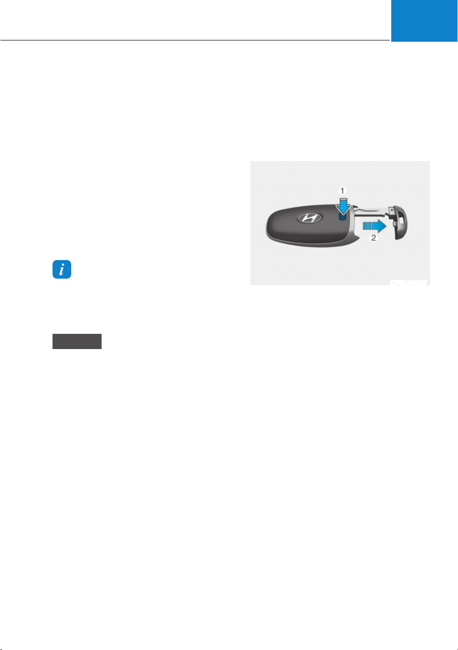
05
5-11
Remotely moving vehicle forward or
backward (if equipped)
With the smart key, the driver can move
the vehicle forward or backward using
the Forward or Backward button (6, 7) on
the smart key.
For more details, refer to “Remote
Smart Parking Assist (RSPA)” section in
chapter 7.
Start-up
You can start the vehicle without
inserting the key.
For more details, refer to the “Start/
Stop Button” section in chapter 6.
Information
If the smart key is not moved for some
time, the detection function for smart key
operation will pause. Lift the smart key to
activate the detection again.
NOTICE
To prevent damaging the smart key:
ś Keep the smart key in a cool,
dry place to avoid damage or
malfunction. Exposure to moisture
or high temperature may cause
the internal circuit of the smart key
to malfunction which may not be
covered under warranty.
ś Avoid dropping or throwing the
smart key.
ś Protect the smart key from extreme
temperatures.
Mechanical key
If the Smart Key does not operate
normally, you can lock or unlock the
driver’s door by using the mechanical
key.
To remove the mechanical key from the
smart key FOB:
OFE048007
1. Press the mechanical key and remove
it from the smart key FOB.
2. Move the release lever in the direction
of the arrow (1) and then remove
the mechanical key (2). Insert the
mechanical key into the key hole on
the door.
To reinstall the mechanical key, put
the key into the hole and push it until
a click sound is heard.
Loss of a smart key
A maximum of three Smart Keys can
be registered to a single vehicle. If
you happen to lose your smart key,
it is recommended that you should
immediately take the vehicle and
remaining keys to your authorized
HYUNDAI dealer or tow the vehicle, if
necessary.

Convenience Features
5-12
Smart key precautions
The smart key may not work if any of the
following occur:
ś The smart key is close to a radio
transmitter such as a radio station or
an airport which can interfere with
normal operation of the transmitter.
ś The smart key is near a mobile two
way radio system or a mobile phone.
ś Another vehicle’s smart key is being
operated close to your vehicle.
If the smart key does not work correctly,
open and close the door with the
mechanical key. If you have a problem
with the smart key, contact an authorized
HYUNDAI dealer.
If the smart key is in close proximity to
your mobile phone, the signal could be
blocked by your mobile phone’s normal
operational signals. This is specifically
relevant when the phone is active such
as making and receiving calls, text
messaging, and/or sending/receiving
emails. When possible, avoid keeping the
smart key and your mobile phone in the
same location such as a pants or jacket
pocket in order to avoid interference
between the two devices.
Information
Changes or modifications not expressly
approved by the party responsible
for compliance could void the user’s
authority to operate the equipment. If the
keyless entry system is inoperative due
to changes or modifications not expressly
approved by the party responsible for
compliance, it will not be covered by your
manufacturer’s vehicle warranty.
Information
7KLVGHYLFHFRPSOLHVZLWK3DUWRIWKH
FCC rules.
Operation is subject to the following three
conditions:
1. This device may not cause harmful
interference, and
2. This device must accept any
interference received, including
interference that may cause undesired
operation.
3. Changes or modifications not expressly
approved by the party responsible
for compliance could void the user’s
authority to operate the device.
NOTICE
ś Keep the smart key away from
electromagnetic materials that
blocks electromagnetic waves to the
key surface.
ś Always have the smart key with
you when leaving the vehicle. If the
smart key is left near the vehicle, the
vehicle battery may be discharged.
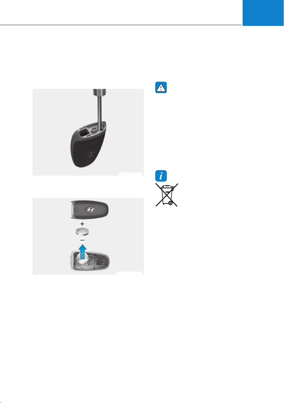
05
5-13
Battery replacement
If the Smart Key is not working properly,
try replacing the battery with a new one.
Battery Type: CR2032
To replace the battery:
OFE048009
If the Smart Key is not working properly,
try replacing the battery with a new one.
ODN8059266
Battery Type: CR2032
To replace the battery:
1. Remove the mechanical key.
2. Use a slim tool to pry open the rear
cover of the smart key.
3. Remove the old battery and insert the
new battery. Make sure the battery
position is correct.
4. Reinstall the rear cover of the smart
key.
If you suspect your smart key might have
sustained some damage, or you feel
your smart key is not working correctly,
contact an authorized HYUNDAI dealer.
WARNING
THIS PRODUCT CONTAINS A BUTTON
BATTERY.
If swallowed, a lithium button battery
can cause severe or fatal injuries within
2 hours. Keep batteries out of reach of
children.
If you think batteries may have been
swallowed or placed inside any part
of the body, seek immediate medical
attention.
Information
An inappropriately disposed
battery can be harmful to
the environment and human
health. Dispose of the battery
according to your local law(s) or
regulations.

Convenience Features
5-14
Immobilizer System
The immobilizer system helps protect
your vehicle from theft. If an improperly
coded key (or other device) is used, the
vehicle is disabled.
When the Start/Stop button is pressed to
the ON position, the immobilizer system
indicator should come on briefly, then
go off. If the indicator starts to blink, the
system does not recognize the coding of
the key.
Press the Start/Stop button to the OFF
position, then press the Start/Stop
button to the ON position again.
In some circumstances, the vehicle may
not recognize your smart key if another
smart key device is nearby or a metal
object such as a key chain is causing
interference with the smart key.
If this occurs, your vehicle may not
start. Remove any metal objects or
additional keys near the smart key before
attempting to start the vehicle again.
If the system repeatedly does not
recognize the coding of the key, contact
an authorized HYUNDAI dealer.
Do not attempt to alter this system
or add other devices to it. Electrical
problems could result that may make
your vehicle inoperable.
WARNING
In order to prevent theft of your
vehicle, do not leave spare keys
anywhere in your vehicle. Your
immobilizer password is a customer
unique password and should be kept
confidential.
NOTICE
The transponder in your key is an
important part of the immobilizer
system. It is designed to give years
of trouble-free service, however you
should avoid exposure to moisture,
static electricity and rough handling.
Immobilizer system malfunction could
occur.
Information
7KLVGHYLFHFRPSOLHVZLWK3DUWRIWKH
FCC rules.
Operation is subject to the following three
conditions:
1. This device may not cause harmful
interference.
2. This device must accept any
interference received, including
interference that may cause undesired
operation.
3. Changes or modifications not expressly
approved by the party responsible
for compliance could void the user’s
authority to operate the device

05
5-15
Hyundai Digital Key
(if equipped)
Digital Key Application
To use Hyundai Digital Key mobile app,
you should install Hyundai digital key
application. Search ‘Hyundai digital key’
in the Google Play Store and download
the app. Please refer to the detailed
manual of the digital key app. The option
can be found under the following app
menu:
0HQXƟ$SSOLFDWLRQ,QIRƟ7XWRULDO
Please note the manual before using the
app.
à This service is only available for
Android smartphones. Please confirm
supported/compatible devices on our
website.
WARNING
For used vehicle
If any of the digital key (smartphone key
or card key) is already registered when
you press ON button after unlocking the
doors, the message ‘Digital key(s) active’
appears on the instrument cluster once.
If you buy a used vehicle, you should
confirm the message and delete the
registered smartphone key and card key.
In addition, please notify the Hyundai
Customer Care Center.
If the card key does not work properly,
please delete the card key and register
the smartphone key and re-register the
card key.
For vehicle maintenance
If you need to have your Digital Key
System repaired or replaced please
ensure your Smartphone Key is still
active. You may have to pair your phone
again.
In the case, re-initialize your Digital Keys
using the Hyundai Digital Key mobile app.
Digital key (smartphone) NFC
function
You can use the Digital Key NFC (Near
Field Communication) function after turn
your smartphone NFC settings on. And
you should unlock & turn on smartphone
screen to use it.
à To change the NFC mode of the
smartphone, please refer to the
smartphone manual or contact
to the customer service center of
smartphone manufacturers.
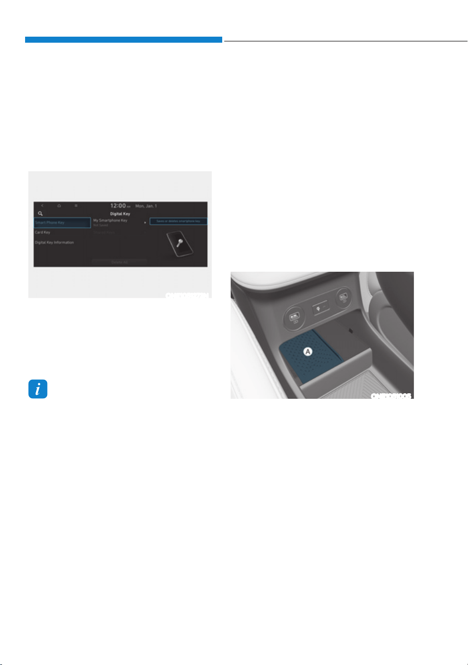
Convenience Features
5-16
Digital key (smartphone)
Hyundai Digital Key (Smartphone)
3DLULQJ
1. Turn the vehicle on with the Smart key
and make sure to keep the smart key
inside the vehicle during digital key
registration.
ONE1051272N
2. Register your Digital key from the
vehicle user setting menu as follows.
From the infotainment screen menu,
go to [Setup] - [Vehicle] - [Digital Key]
- [Smart Phone Key] then select the
[Save] from submenu.
Information
The [Save] button will be disabled if the
digital key (Smartphone key) is already
saved.
3OHDVHUHIHUWR³'LJLWDO.H\'HOHWH´LQWKLV
manual and follow the digital key delete
procedure in your car before Digital key
save.
3OHDVHUHIHUWRWKHµ7XWRULDO¶RQ\RXU
Digital key app and delete the previous
saved key in your smartphone before save.
3. Select the vehicle to save on your
Digital key application and activate
the save mode.
à Save mode is available only on
the vehicle owner’s Digital key
application.
4. Place the backside of smartphone
onto the wireless charging pad(in-
vehicle authentication pad).
The saving process will begin
automatically.
5. Once the digital key save is complete,
a message will be shown on the
infotainment screen or cluster.
6. Remove the smartphone from the pad
and complete the saving process.
ONE1051005
[A] : Wireless Charging Pad (In-vehicle Authentication
Pad)
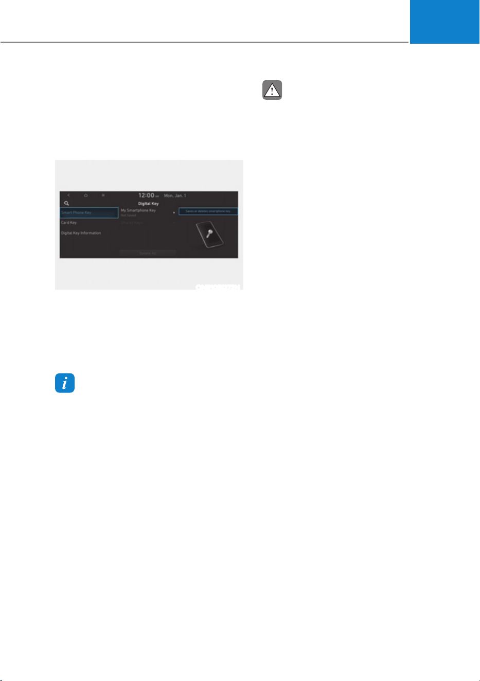
05
5-17
Hyundai Digital Key (Smartphone Key)
Deletion
1. Turn the vehicle on with the Smart
key and make sure to keep the smart
key inside the vehicle during delete
process.
ONE1051272N
2. Delete your Digital key from the
vehicle user setting menu as follows.
From the infotainment screen menu,
go to [Setup] - [Vehicle] - [Digital Key]
- [Smart Phone Key] then select the
[Delete] from submenu.
Information
The [Delete] button will be disabled if there
is no digital key (Smartphone key) saved.
3. Once the digital key delete is
complete, a message will be shown
on the infotainment screen or cluster.
4. Go to [Initialize Digital Key] menu on
the digital key application and select
the vehicle to delete the digital key
information.
ś 2SHQWKH+\XQGDL'LJLWDO.H\DSSƟ
0HQXƟ,QLWLDOL]H'LJLWDO.H\
à If the saved digital key information
in your car is deleted due to vehicle
maintenance, the digital key in your
smartphone should be deleted as well.
à For more information, please refer to
the ‘Tutorial’ on your Digital key app.
CAUTION
ś If the smartphone is removed
from the interior authentication
pad during enrollment, the saving
process will be cancelled.
ś If the infotainment or instrument
cluster screen is changed during
enrollment, the saving process will
be cancelled.
ś If the vehicle is turned off during
enrollment, the saving process will
be cancelled.
ś If the gear is shifted, the saving
process will be cancelled.
ś If you try to save the smartphone
which is not logged in with the
vehicle owner’s ID or if you try to
save the Card key, the saving process
will not begin.
ś If the NFC setting on your
smartphone is off, the saving process
will not begin.
ś If the smartphone screen is changed
to off or locked status, the saving
process will be cancelled.
ś If there is no Smart key during the
save process, the saving process will
not begin.
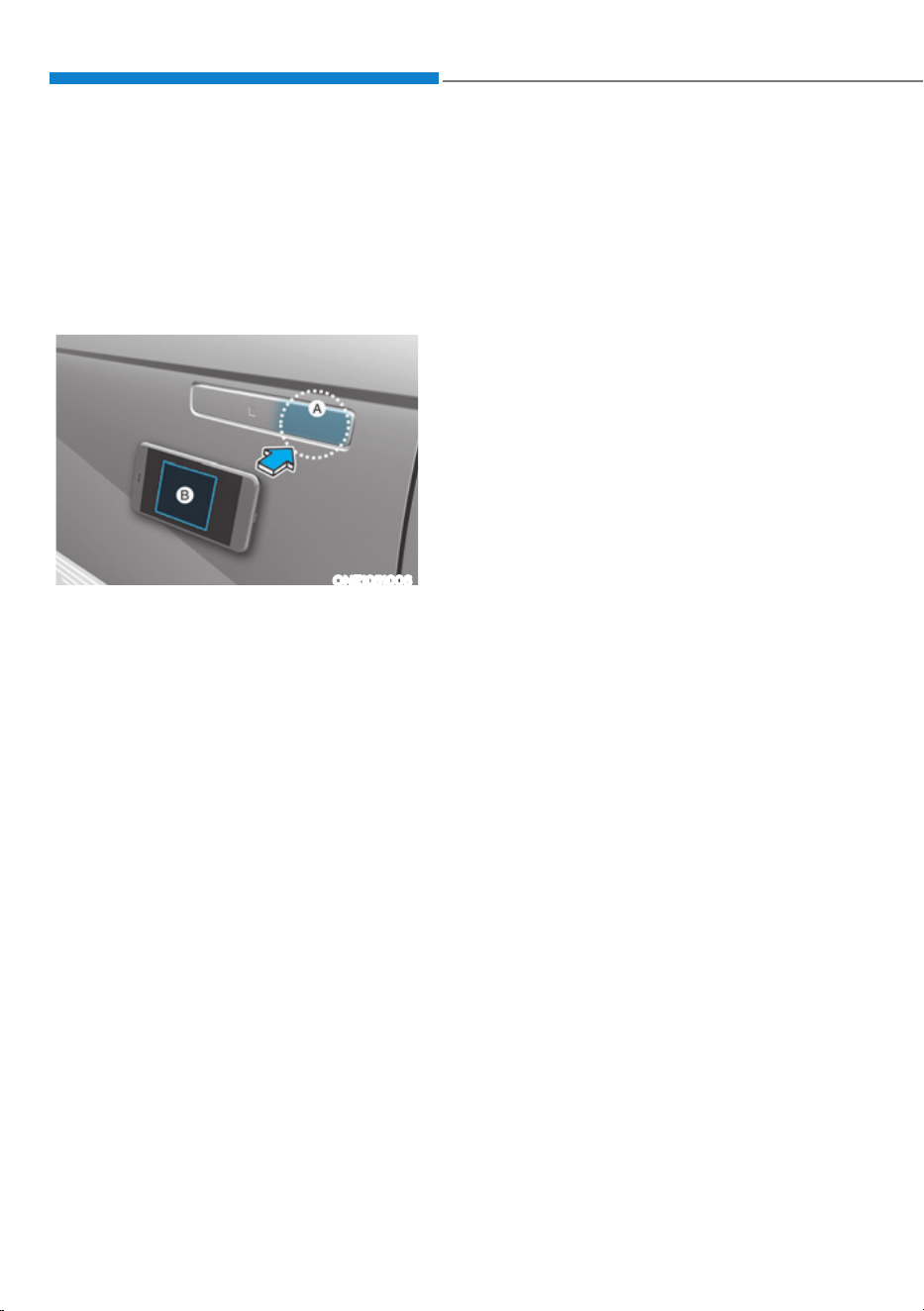
Convenience Features
5-18
Set up main vehicle
You can manage multiple digital keys
from the Digital key app. From the list of
digital keys you own, select the vehicle
you want to make your priority vehicle.
For more information, please refer to
the ‘Tutorial’ on your Digital key app.
ONE1051006
[A] : Door handle authentication pad
[B] : NFC Antenna in the rear side of smart phone
NFC door lock/unlock
You should contact your smartphone’s
NFC antenna(backside of phone) to door
handle authentication pad (A) marked
position near by the lock button) of
driver’s (or front passenger’s) outside
door for 2 seconds to lock or unlock the
doors. If the Two Press Unlock feature
is applied (press twice for unlocking),
driver’s seat door will be unlocked by
contacting the digital key (smartphone
key). In this state, if you contact one
more time within 4 seconds, all the doors
unlock. Please make sure the doors are
locked. If you do not open any of the
doors after unlocking, it automatically
re-lock after 30 seconds.
Note that you cannot lock your vehicle
when you contact NFC antenna in the
smartphone to the door handle pad if
any of the following occurs:
ś The Proximity / Smart Key is in the
vehicle.
ś The Engine Start/Stop button is in
ACC or ON position.
ś Any of the doors, hood and trunk is
opened.
If the smartphone digital key does not
work, please remove the smartphone
more than 4 inches (0.1 m) from the door
handle authentication pad and try it
again.
After unlock the door or start up the
vehicle with digital key, even though
the driver tries to lock the doors by the
central door lock switch, the door lock
will be once locked and immediately
released at the moment of door closed.
Start-up with Digital Key
1. After placing your registered
smartphone onto the interior
authentication pad (wireless charger),
step on the brake and press the
Engine Start/Stop button.
2. After start-up, the digital key data
will be automatically updated. It
takes 5 to 20 seconds, after that,
the smartphone can be go into the
wireless charging mode automatically.
Once the engine started, you can
remove the smartphone from the pad.
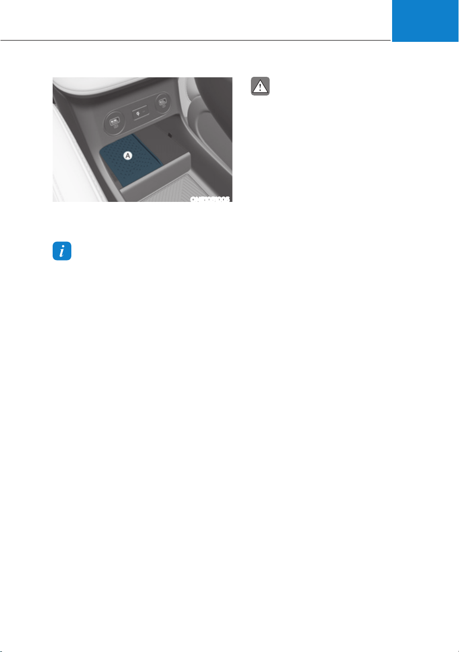
05
5-19
ONE1051005
[A] : Wireless Charging Pad (In-vehicle Authentication
Pad)
Information
After reconnecting the vehicle battery
power supply or charging the battery, it
may take time to operate due to remote
UHQHZDORIVHFXULW\LQIRUPDWLRQ:KHQ\RX
lock or unlock the door with NFC, please
contact and hold your smartphone on the
door handle until it works.
The solution allows for offline mode usage
when the mobile data connection of the
VPDUWSKRQHLVZHDN:KHQ\RXDUHLQWKH
place where the mobile data connection
of your smartphone is available and
place your smartphone on the interior
authentication pad (wireless charger) and
start up your vehicle or contact the digital
key on the door handle to lock or unlock
the door, the remote renewal of security
information starts automatically. Even
though the engine is turned on, please
wait until the remote renewal process
is completed and wireless charger is
converted to charging mode.
CAUTION
The engine can be turned on if the
registered smartphone or card key is
placed on the interior authentication
pad (wireless charger). Do not leave
unsupervised children or people who
are not aware of the system since it
can result in serious injury or death.
Always have the registered digital key
(smartphone) or card key with you to
prevent vehicle theft when leaving the
vehicle.
For more information, refer to the
Engine Start/Stop button in chapter 6.

Convenience Features
5-20
Remote Control with Digital Key
To use the remote control function with
your android smartphone, Bluetooth
must be turned on.
Remote Control Connection with Digital
Key
1. Open Hyundai digital key application
on the smartphone. Select the
vehicle to activate the remote control
function as a main vehicle.
2. Approach with the activated
smartphone app to your vehicle
and you can check whether the
connection is available. If it enables
your smartphone to connect, connect
with your vehicle by pressing the
connect button. The remote control
function is activated after completing
the process.
Remote Control Operation with Digital
Key
You can execute the remote control
operation including door lock/unlock,
panic on/off, remote start / remote
stop and trunk opening. The icon for
each function will be highlighted and
alarm/vibration also provided when the
operation is performed.
Note that you cannot lock your vehicle
using the Hyundai digital key app if any
of the following occurs:
ś The Engine Start/Stop button is in
ACC or ON position.
ś Any doors are open.
When the smartphone and the vehicle
are connected by the Bluetooth function
but the remote control command
cannot be received over 5 minutes, the
remote control connection is cancelled
automatically.
CAUTION
ś If metallic window tint was applied
to your vehicle, it may cause
bad Bluetooth connection or
performance degradation of the
digital key.
ś If multiple users operate the remote
control function simultaneously, the
connection between the digital key
and the vehicle might result in failed
commands. Please connect and
operate the remote control function
only the necessary user.
ś When using the remote control
operation, the driver (the remote
control user) should leave the vehicle
after confirming the door lock (the
chime sounds once and the hazard
warning lights blink).
ś The remote functions of the Digital
Key app enables the vehicle to be
controlled from a set distance. If
the digital key or the vehicle goes
beyond the operable distance, the
remote control function might be
disconnected or cancelled.
ś If the digital key (smartphone) is
connected with the vehicle for the
remote control, the driver with the
key goes far away from the vehicle,
the function might not work.
ś If the remote control operation
is executed where the mobile
connection is weak, Bluetooth
connection is poor due to several
Bluetooth devices or there is an
object such as metal or concrete, it
might be delayed or the operable
distance might decrease. You should
not cover the smartphone with your
hand or place other devices which
can cause frequency interference. It
may result in poor performance.
ś If the remote control function is not
available, please use NFC function to
lock or unlock the doors.

05
5-21
Remote Start with Digital Key
ś When the shift button of your vehicle
is in P (Park) and all of the doors
including trunk and hood is locked
and the vehicle is off, press the Door
Lock button in the Hyundai Digital
Key app then press the Remote Start
button within 4 seconds.
You can confirm the engine is on if the
hazard warning lights blinks two times
and the chime sounds.
ś If you want to turn off the engine,
press Remote Engine Stop. Air
Conditioner / Heating system
maintains the same status as when
you last used the vehicle.
ś Unless you put the registered digital
key(smartphone) on the interior
authentication pad (wireless charger)
when the remote start function is on,
the engine will turn off.
ś If you do not get on the vehicle within
10 minutes after the engine turns on,
the vehicle will turn off.
For more information, refer to the Engine
Start/Stop button in chapter 6.
Vehicle information Display
The digital key application displays
the vehicle information such as
driving or door conditions through the
communication with the vehicle.
ś How to check : Select the vehicle
what you want to check and touch
the vehicle image, then vehicle
information display page will be
shown.
ś Contents : accumulated odometer,
latest fuel economy, driving range,
fuel remaining, tire pressure, doors
lock/unlock status and last data
updated time.
à Displayed vehicle date could be
differed from the current vehicle
condition.
à For more information, please refer to
the ‘Tutorial’ on your Digital key app.
Smartphone change/App deletion
If you change your smartphone or delete
the Hyundai Digital Key App, please refer
to the following to set up your Digital
Key:
Smartphone Change/ Reset
If you change or reset the smartphone,
the registered digital key in your previous
smartphone may not be used. Please
refer to following procedure to use the
digital key.
1. Install the digital key application and
log in.
2. If you are the owner, retry the Digital
key save process.
3. If you are the sharer, need to re-share
the key from owner.
App delete & reinstall/ Delete App data
You can re-download the digital key
from server in these cases as follow
procedure.
1. Reinstall the application and log in.
2. Input the PIN number for user
verification.
3. If PIN is correct, digital key data
will be re-downloaded to your
smartphone and you can use it
without any further registration or
sharing.
Smartphone operability with Digital Key
The digital key application may not
be available to old type smartphones.
Please check the available smartphone
models with your dealer. NFC antenna
position on the smartphone can be
confirmed on each smartphone’s manual
or contact to customer service center of
the smartphone manufacture.

Convenience Features
5-22
CAUTION
ś Do not leave the registered digital
key (smartphone) and card key in
your vehicle. Please carry around
your keys all the times.
ś If you happen to lose your digital
key (smartphone) or card key
registered as a main user’s key, you
should immediately delete the key
on the vehicle’s key menu. For more
information, refer to the Digital Key
Deletion in this chapter.
ś If you registered your digital key
(smartphone) or card key in the
vehicle, a message appears on the
instrument cluster and let you know
the key is registered.
(Message: Digital key(s) active.)
ś If you buy a used vehicle, you should
confirm the message and delete the
registered smartphone key and card
key. In this case, you should carry
your smart key.
ś If you keep place the NFC card
of the digital key on the interior
authentication pad (wireless
charger) while driving, it may cause a
malfunction of the NFC card.
ś You should remove your NFC card
of the digital key on the interior
authentication pad after turning on
the engine.
ś Hyundai digital key app may not
work properly when the NFC or
Bluetooth communication between
smartphone and car is not good.
ś If the remote control operation
is executed where the mobile
connection is weak, Bluetooth
connection is poor due to lots of
Bluetooth devices or there is an
object such as metal or concrete, it
might be delayed or the operable
distance might decrease. Especially,
you should not cover the smartphone
with your hand or place other
devices which can cause frequency
interference. It may result in poor
performance.
ś If the remote control function is not
activated, please use NFC function to
lock or unlock the doors
ś You should be careful not to
press the remote control button
on the digital key (smartphone)
accidentally.
ś If the digital key (smartphone) is
discharged or defective or you
cannot use the digital key since the
vehicle battery is discharged, use the
inside door lock button to lock all of
the doors.

05
5-23
CAUTION
ś Hyundai digital key app on the
smartphone and card key may not
work if any of the following occurs:
- Hyundai digital key app on the
smartphone is deleted. (Required
to reinstall the app)
- Account log in information of
Hyundai digital key app is expired.
(Required to re-log in)
- When you try to log in to another
smartphone instead of the
registered smartphone with same
user account.
- Smartphone rooting or app
hacking is detected.
- Smartphone battery or the vehicle
battery is discharged.
- Smartphone’s screen is off or
locked.
- NFC or Bluetooth is turned off on
the smartphone settings.
- Smartphone’s mobile network
setting is off or airplane mode is
activated.
- A credit card is overlapped in the
back of your smartphone or metal
or thick case is used.
- Use the card key with insert it
into the wallet or card holder or
overlapping with other cards.
- If you use a smart phone cover that
uses wireless communication or is
made of metal, the digital key NFC
function may not work properly.
Remove the smart phone cover
before using the digital key NFC
function.
śThe vehicle may not be controlled by
the smartphone if any of the following
occurs:
- Basic and necessary functions of
the smartphone manufacturer are
operating. (General call, urgent
call, audio or NFC payment)
- Wireless earphone is operating.
(General call, urgent call or audio)
- The digital key app function such
as basic setting or app launching
is limited by prior policy according
to the manufacturer while using a
smartphone produced by domestic
and foreign manufactures.
à If you change the smartphone
number, you should modify the user
account information on the HYUNDAI
customer web site to use the digital
key app.
à If the vehicle owner changes
the smartphone device, the new
smartphone should be registered in
the car after deleting the registered
digital key(smartphone).
à If a sharer changes or reset the
smartphone, the key should be re-
shared from owner.
à Some of the old smartphone may
not work properly. Please check the
available smartphone models with
your dealer.
à NFC antenna position on the
smartphone can be confirmed
on each smartphone’s manual or
contact to customer service center
of the smartphone manufacture.

Convenience Features
5-24
Digital key (Card key)
Digital key (Card key) save
1. Install Hyundai digital key app in
main user’s smartphone and register
the digital key (smartphone). Please
refer to the registration method of the
digital key (smartphone).
2. Using the [Pair Card Key] menu on
the digital key application, you can
activate the Card Key registration
mode.
à NFC authentication : enter the NFC
authentication menu and contact
the smartphone on the outside door
handle.
à Bluetooth authentication : enter the
Bluetooth authentication menu and
press the [OK] button for activation.
If you activate the registration mode,
you should complete the Card saving
process within 5 minutes.
à If you have not registered the digital
key (smartphone), please register the
digital key (card key) with two smart
keys.
3. Register the NFC card key on the
User’s Settings menu after turning on
the vehicle.
ONE1051273N
From the infotainment screen menu,
go to [Setup] - [Vehicle] - [Digital Key]
- [Card Key] then select the [Save]
from submenu.
The [Save] button will be disabled if
the digital key (Card key) is already
saved.
Please refer to “Digital Key Delete” in
this manual and follow the digital key
delete procedure in your car before
Digital key save.
4. Place the NFC card key onto the
interior authentication pad (wireless
charger). The saving process will
begin automatically.
5. If the key is enrolled, the message
will be displayed on the infotainment
screen or instrument cluster.
ś Once the card key registration mode
is activated, the process should be
completed within 5 minutes. After
then, you should reactivate once
again for registration.
ś For the digital key(card key) saving,
the smart key(fob) must be exist inside
of vehicle.
ś Once a Card key is registered, it
cannot be reuse onto another vehicle.
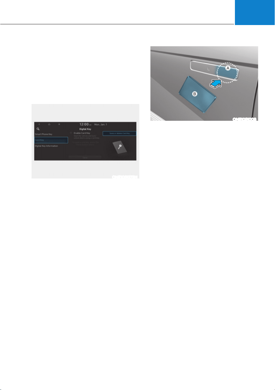
05
5-25
Digital key (Card key) deletion
You should have the smart key to delete
the digital key (card key) so please carry
around the key.
1. Get on the vehicle with the smart key.
2. Delete the NFC card key on the User’s
Settings menu after turning on the
engine.
ONE1051273N
From the infotainment screen menu,
go to [Setup] - [Vehicle] - [Digital Key]
- [Card Key] then select the [Delete]
from submenu.
If there is no saved digital key(card
key), [Delete] menu will not be
activated.
ś To delete the saved digital key (card
key), the smart key must be exist
inside the vehicle.
ś The deleted digital key (card key) can
be re-registered before registering a
new digital key (card key).
ś If you try to register a new digital key
(card key), the previously registered
digital key (card key) cannot be used
again.
ONE1051008
[A] : Door handle authentication pad
[B] : NFC Antenna of the card key
NFC door lock/unlock
You should contact digital key (card key)
to door handle authentication pad (1,
marked position near by the lock button)
of driver’s (or front passenger’s) outside
door for 2 seconds to lock or unlock the
doors. If the Two Press Unlock feature
is applied (press twice for unlocking),
driver’s seat door will be unlocked by
contacting the digital key (card key). In
this state, if you contact one more time
within 4 seconds, all the doors unlock.

Convenience Features
5-26
Inoperable condition
If you do not contact the digital key (card
key) to the center of the door handle
authentication pad accurately., it may
not work. In addition, if you overlap and
use the key with NFC-enabled cards such
as transportation card or credit card, it
does not work.
Note that if you try to lock your vehicle
with digital key (card key) in following
cases, the doors will not be locked and
chime will sound for 3 seconds.
ś The Smart Key is in the vehicle.
ś The Engine Start/Stop button is in
ACC or ON position.
ś Any of the doors, hood and trunk are
open
If the digital key (card key) does not
work, please detach the key around
4 inches (0.1 m) from the handle
authentication pad and retry to contact.
The card key may be damaged by the
impact. It would not work properly if
the key is damaged. You should buy a
new card and register again. Long-time
exposure to high temperature may cause
the card key to malfunction. Please be
careful not to expose the key to direct
sunlight or high temperature.
After unlock the door or start up the
vehicle with digital key, even though
the driver tries to lock the doors by the
central door lock switch, the door lock
will be once locked and immediately
released at the moment of door closed.
Start-up with Card key
After placing your registered card key
onto the interior authentication pad
(wireless charger), step on the brake and
press the Engine Start/Stop button.
WARNING
ś If you do not place the digital key
(card key) onto the center of the
interior authentication pad (wireless
charger) exactly, the card key may
not be recognized. If the engine is
not turned on, adjust and place the
key again.
ś If you overlap and use the key
with NFC-enabled cards such as
transportation card or credit card,
the card key may not be recognized.
ś If the digital key (card key) does not
work, please detach the key around
4 inches (0.1 m) from the handle
authentication pad and retry to
contact.
ś The card key may be damaged due to
impact. It would not work properly if
the key is damaged. You should buy a
new card and register again.
For more information, refer to the
Engine Start/Stop button in chapter 6.

05
5-27
Digital key application/cancellation
If you do not want to use the digital key
(smartphone and card key), you can
disable the function temporarily. You
should have the smart key when you
change the settings
From the infotainment screen menu,
go to [Setup] - [Vehicle] - [Digital Key] -
[Enable Digital Keys] (deselect)
Information
For the digital key disable, the smart key
must be exist inside the car. For the digital
key enable, the smart key is not needed.
CAUTION
If you uncheck Enable digital keys, it is
impossible to lock or unlock the doors
or start up the vehicle with digital keys
such as smartphone and card key. If
you check Enable digital keys again, the
registered digital keys(smartphone and
card key) are available. Even though
you stop the digital key function, the
registered keys (smartphone and card
key) are not deleted.
Personalized profile and vehicle
settings
Connect the registered digital key with
personalized profile. Then in case you
lock or unlock the door with the digital
key NFC function or unlock the door
remotely by digital key application
Bluetooth connection, the vehicle
will play the personalized user profile
settings. Profile connection and
personalization are available for Driver 1
and Driver 2.
3URILOHOLQNXQOLQNHG
Profile link
6HOHFW6HWXSƟ8VHU3URILOHƟ
3URILOH6HWWLQJVƟ/LQN'LJLWDO.H\
(Smartphone) on the infotainment
system menu.
2. Unlock and place your smartphone on
the wireless charger according to a
message and it automatically starts to
interwork.
3. It begins the profile link with a
message.
4. If you select Link, the registered
phone number’s digital key and the
user’s profile are linked.
5. The interconnection process is
completed with a message.

Convenience Features
5-28
Profile unlink
1. Select Digital Key information on
infotainment Vehicle Settings menu. It
is possible to unlink only if the profile
is interconnected.
2. Profile unlink is completed with a
message.
Information
If you connect both Driver 1 and Driver 2
with a single smartphone, the smartphone
digital key always works as Driver 1.
If you unlink the Driver 1, personalization
function will operate as Driver 2.
PRECAUTION for vehicle profile link and
unlink
When you link or unlink the profile of
digital key, you should be careful of the
following.
ś Profile link is possible to use with the
digital key. (Infotainment Vehicle
6HWWLQJV0RGHƟ'LJLWDO.H\Ɵ(QDEOH
Digital Keys)
ś Profile link information remains even
when you set the digital key function
disable.
ś Only the smart phone with digital key
app enables you to link your profile.
(Impossible to link with NFC card)
ś Profile link works only when the
smart phone and the digital key are
registered to the vehicle. The smart
phone with another vehicle’s digital
key cannot link profile.
ś If you remove the smart phone
from the wireless charger before
completing the profile link, it does not
work.
ś To unlink the profile, the smart phone
does not need to be on the wireless
charger.
9HKLFOHSHUVRQDOL]DWLRQRSHUDWLRQ
The personalization function linked with
digital key works as following conditions:
ś Contact the driver’s door handle with
the profile linked smart phone to lock
or unlock the doors (Personalization
does not operate when locking or
unlocking the front passenger door.)
ś Remote door unlock with the profile
linked smartphone digital key app.
The profile linked with digital key can be
changed manually in the infotainment
system setup screen.
3UHFDXWLRQIRUGLJLWDONH\SURILOHOLQNDQG
unlink
Profile operation according to door lock/
unlock system is as follows.
Item
Personalization
Operation
Initial value Guest
Profile linked
smart phone
key
Linked profile
Profile unlinked
smart phone
key
Recently activated
profile
NFC card key
Smart key
ś The personalization function using
the digital key can be operated
after linking the digital key on the
infotainment system profile menu.
ś You should use the personalization
function during stopping your vehicle
safely.

05
5-29
9HKLFOHSHUVRQDOL]DWLRQZLWKGLJLWDONH\
The available personalization function in the vehicle is as follows.
System Personalization Item
USM
HUD
Display mode, Display control, AR matching
adjustment, Content selection
Lamp Blink number of one-touch signal lamps
Cluster
Information display on the cluster, Voice volume,
Welcome sound, Theme selection
Seat/Mirror -
Door Automatic door lock/unlock, Two Press Unlock
Air conditioning
Temperature unit, shut off outside air (interlocked
with washer fluid), Automatic ventilation, Auto
defogging on/off
Convenience Wireless charging system on/off
NFC
Digital key on/off, Smartphone Key Paring/Deletion,
Card key Save/Delete
AVN
Navigation
Preferred volume of the navigation system, Recent
destination
User preset Radio preset
Phone
connectivity
Bluetooth preferential connect CarPlay/Android
Auto/MirrorLink On/Off
Air conditioning
Operating
condition
Latest operation setup of the following functions:
Temperature, AUTO, air flow direction, air volume,
air conditioner, air intake control, SYNC, Front
windshield defroster, OFF
Driving Smart mode -
For more information of personalization, refer to the infotainment system manual.
CAUTION
If you leave the digital key after locking or unlocking the doors or starting up the
vehicle with the smart key, the doors can be locked by the central door lock. Please
carry around the digital key all the time.
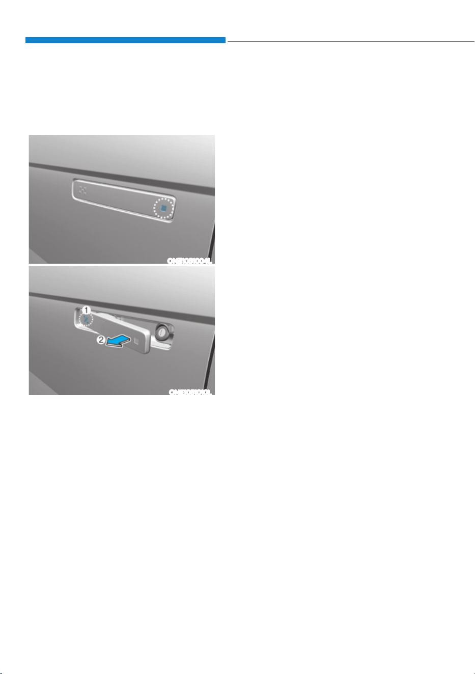
Convenience Features
5-30
DOOR LOCKS
Operating Door Unlocks from
Outside the Vehicle (Manual
type)
Smart key
ONE1051004L
ONE1051010L
Push the button on the front outside
door handle (the engraved part) while
carrying the Smart Key with you, all
doors will unlock.
The hazard warning lights will blink twice
and chime also sounds twice.
Once the doors are unlocked, when press
the front of the door handle (1) then rear
of the door handle will pop out (2).
Pull the outside door handle to open the
door.
Operating Door Unlocks from
Outside the Vehicle (Electric
type) (if equipped)
Smart key
Approach unlock system
The outside door handle will slide out
and the doors will unlock when the driver
approaches the vehicle possessing the
smart key.
The driver can activate/deactivate
the “Approach unlock” system on the
infotainment screen.
To activate Approach unlock system for
only the driver’s seat, select ‘Settings
Ɵ9HKLFOHƟ'RRUƟ5HPRWHSRZHU
GRRURSHQƟ8QORFNDOOGRRUVŔLQWKH
infotainment system screen.
To activate Approach unlock system,
VHOHFWœ6HWWLQJVƟ9HKLFOHƟ'RRU
ƟDFWLYDWHDSSURDFKXQORFNŔLQWKH
infotainment system. The outside door
handle will slide out and the door will
unlock when the driver approaches
the vehicle possessing the smart
key. If Approaching unlock system
is deactivated, the door handle will
not slide out even when the driver
approaches to the vehicle with the smart
key. To unlock doors when Approach
unlock system is deactivated, touch the
lock/unlock sensor(engraved part) on the
handle.
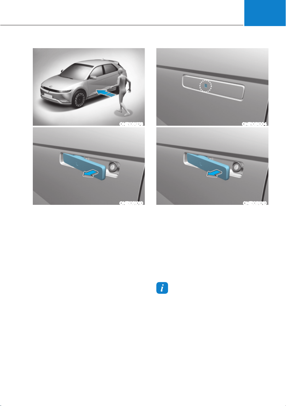
05
5-31
ONE1051276
ONE1051010
ś When the “Approach unlock” is
activated :
- If you approach (within 1 m) the
driver or front passenger’s door
handle possessing the smart key,
the outside door handles slide out
and the doors are unlocked. In this
case, Hazard Warning Flasher blinks
twice and chime also sounds twice.
- After first approach, the vehicle
tries detecting the smart key
every 5 seconds and if the key is
not detected, the doors will lock
automatically and the handles will
slide in.
ONE1051004
ONE1051010
ś When the “Approach unlock” is
deactivated : The handle does not
slide out even when you approach
with the smart key in possession. The
doors are unlocked if you press the
outside handle as the handles slide
out.
ś The doors will lock automatically
and the handles will slide in after 30
seconds unless a door is opened.
Information
In emergency situations, such as battery is
dead, the outside electric door handle can
still be operated in a way that the outside
manual door handle operate.
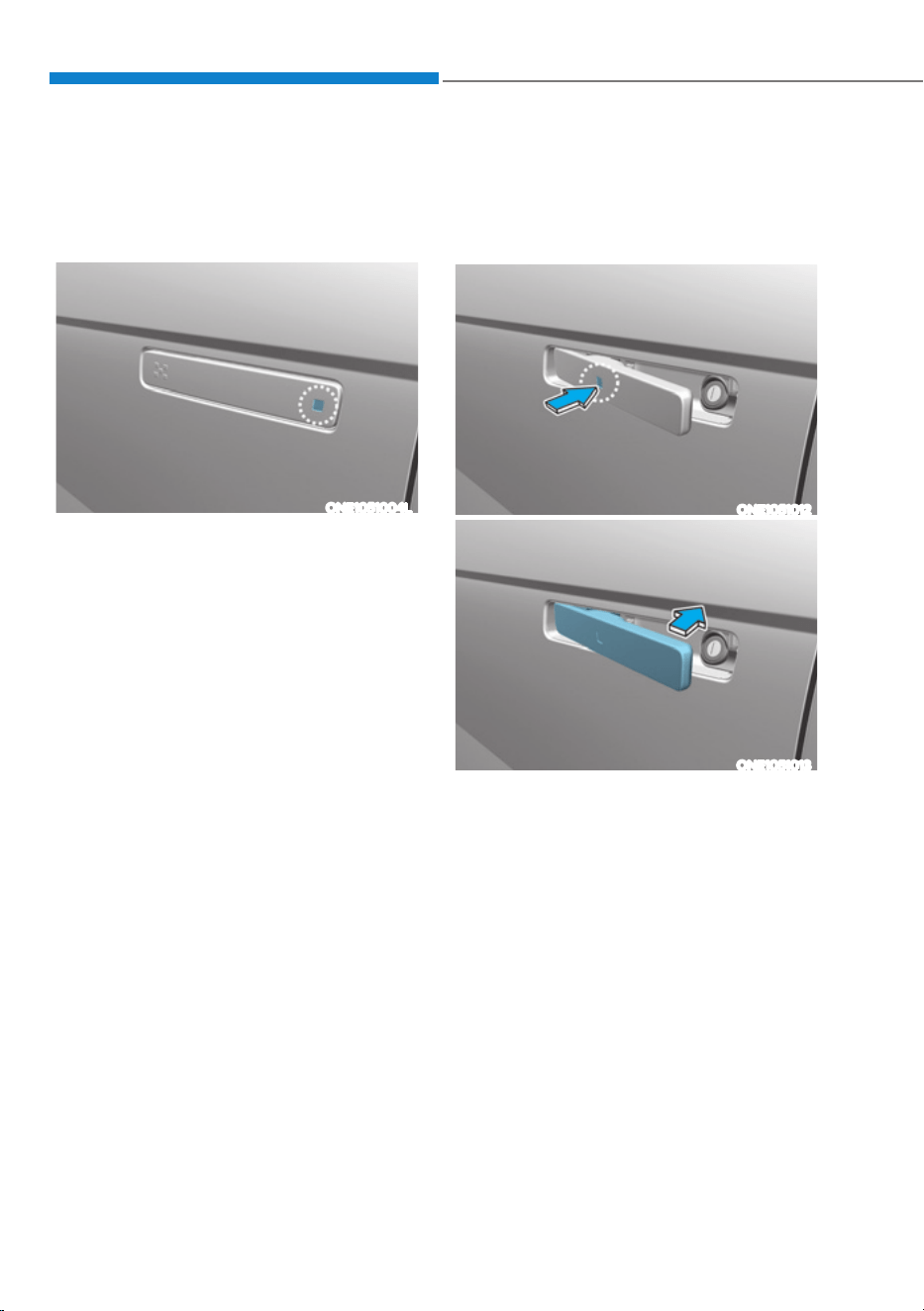
Convenience Features
5-32
Operating Door Locks from
Outside the Vehicle (Manual
type)
Smart key
ONE1051004L
Push the button on the front outside
door handle (the engraved part) while
carrying the Smart Key with you, all
doors will lock.
The hazard warning lights will blink and
chime also sounds once.
Push the door to close.
Operating Door Locks from
Outside the Vehicle (Electric
type) (if equipped)
Smart key
ONE1051012
ONE1051013
When all doors are closed, touch the
touch sensor on the front outside door
handle (the engraved part) while carrying
the Smart Key with you, outside door
handle will return and doors will be
locked.
The hazard warning lights will blink and
chime also sounds once.
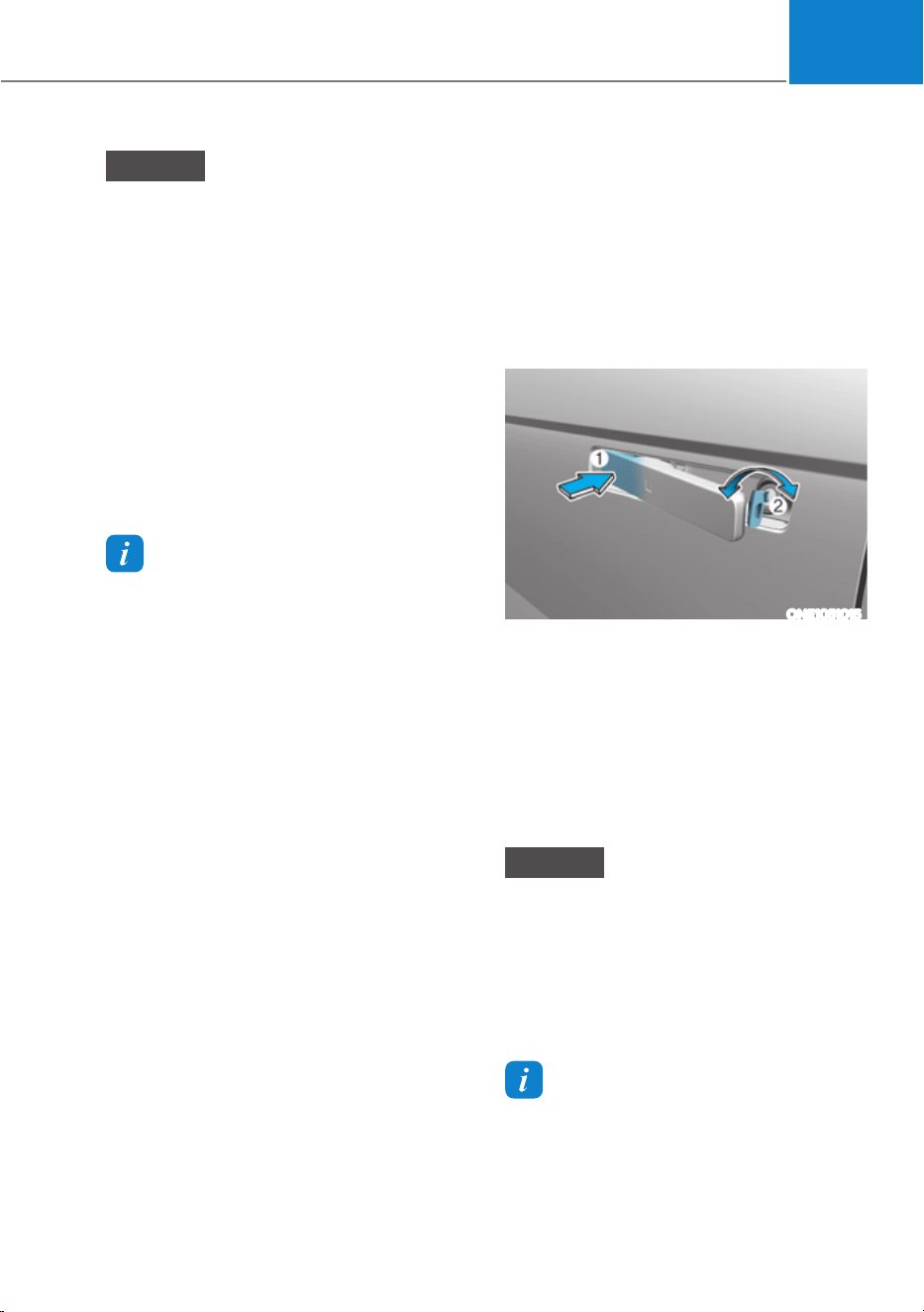
05
5-33
NOTICE
ś If the door is locked/unlocked
multiple times in rapid succession
with the smart key, door lock button
or door lock switch, the system
may stop operating temporarily in
order to protect the circuit. Also,
the “Approach unlock” system may
not operate. Try operation after a
sufficient time in case the system
does not operate due to multiple
operations.
ś “Approach unlock” system is not
operated continuously. Retry after a
certain period of time when all the
doors are closed.
Information
ś In cold and wet climates, door lock
and door mechanisms may not work
properly due to freezing conditions.
ś If the door is locked/unlocked multiple
times in rapid succession with either
the vehicle key or door lock switch, the
system may stop operating temporarily
in order to protect the circuit and
prevent damage to system components.
ś :KHQZDVKLQJWKHYHKLFOH
- Self car wash
Keep the door locked with the outside
door handle closed.
To keep the door unlocked, push
back the outside door handle by
hand. This function prevents the door
handle from being damaged, and the
door handle pops out again when the
unlock button is pressed.
- Auto car wash
Keep the door locked with the outside
door handle closed.
If the Smart Key is not in the vehicle,
turn off the vehicle and stay the
Smart Key away at least 2 m (78
in.) from the vehicle to prevent the
outside door handle operates.
Digital key (if equipped)
Refer to ‘HYUNDAI digital key’ of this
chapter to lock or unlock the door from
outside vehicle with digital key.
Pull the outside door handle to open the
door after unlocking the door. Push the
door to close.
Mechanical key
ONE1051015
Press the front part (1) of the door
handle to pull out the rear part of the
door handle. While keep pressing the
front part of the door handle, insert the
mechanical key to the lock.
To lock the door, turn the key toward the
front (left side) of the vehicle. To unlock,
turn the key toward the rear (right side)
of the vehicle.
NOTICE
Do not apply excessive force on the
door and door handle. It may damage
the door and door handle.
The mechanical key only locks/unlocks
the driver’s door handle. For more
detail, refer to ‘In case of an emergency’
in this chapter.
Information
:KHQWKHGRRUKDQGOHRUWKHNH\KROH
freeze and do not open, lightly tap or
indirectly warm (for example, hand
temperature) the keyhole.
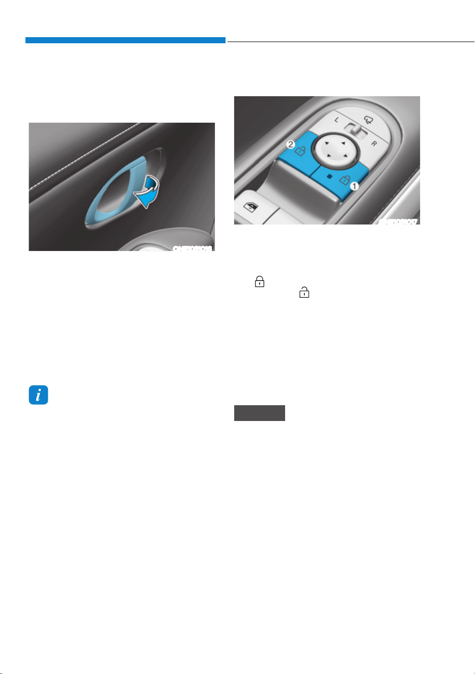
Convenience Features
5-34
Operating Door Lock/Unlock
from Inside the Vehicle
With the door handle
ONE1051016
Front door
If the inner door handle is pulled when
the door is locked, the door will unlock
and open.
Rear door
If the inner door handle is pulled once
when the door is locked, the door will
unlock. If the inner door handle is pulled
once more, the door will open.
Information
If a power door lock ever fails to function
while you are in the vehicle try one or
more of the following techniques to exit:
ś Operate the door unlock feature
repeatedly (both electronic and
manual) while simultaneously pulling
on the door handle.
ś Operate the other door locks and
handles, front and rear.
ś Lower a front window and use the
mechanical key to unlock the door from
outside.
With the central door lock switch
ONE1051017
Driver’s and front passenger’s door
The driver’s and front passenger’s door
armrest is equipped with a central door
lock switch. The lock switch is indicated
by a
symbol. The unlock switch is
indicated by a
symbol.
When the lock switch (1) is pressed (door
indicator light ON), all the vehicle doors
will lock.
When the unlock switch (2) is pressed, all
the vehicle doors will unlock.
If the smart key is in the vehicle and any
door is open, the doors will not lock even
though the lock switch (1) is pressed.
NOTICE
If the smart key is in the vehicle and the
front door is opened, the central door
lock button (1) cannot lock the doors.
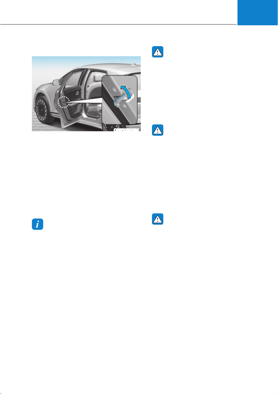
05
5-35
In case of an emergency
ONE1051019K
In case of emergency such as when the
battery is discharged, the only way to
lock the door(s) is with the mechanical
key from the outside key hole.
Doors without an outside key hole can be
locked as follows:
1. Open the door.
2. Insert the key into the emergency
door lock hole and turn the key to the
lock position.
3. Close the door securely.
Information
If the electrical power door lock switch
does not operate (ex. dead car battery) and
the liftgate is closed, you will not be able to
open the liftgate until power is restored.
WARNING
ś The doors should always be fully
closed and locked while the
vehicle is in motion. If the doors
are unlocked, the risk of being
thrown from the vehicle in a crash is
increased.
ś Do not pull the inner door handle of
the driver’s or passenger’s door while
the vehicle is moving.
WARNING
Do not leave the elderly, children or
animals unattended in your vehicle. An
enclosed vehicle can become extremely
hot, causing death or serious injury
to the elderly, unattended children
or animals who cannot escape from
the vehicle. Children might operate
features of the vehicle that could injure
them, or they could encounter other
harm, possibly from someone gaining
entry to the vehicle.
WARNING
Always secure your vehicle.
Leaving your vehicle unlocked increases
the potential risk to you or others from
someone hiding in your vehicle.
To secure your vehicle, while
depressing the brake, shift the gear
to the P (Park) position, engage the
parking brake, and press the Start/
Stop button to the OFF position, close
all windows, lock all doors, and always
take the key with you.

Convenience Features
5-36
CAUTION
Opening a door when something is
approaching may cause damage or
injury. Be careful when opening doors
and watch for vehicles, motorcycles,
bicycles or pedestrians approaching the
vehicle in the path of the door.
WARNING
If you stay in the vehicle for a long time
while the weather is very hot or cold,
there are risks of injuries or danger to
life. Do not lock the vehicle from the
outside when someone is in the vehicle.
Automatic Door Lock and Unlock
Features
Your vehicle is equipped with features
that will automatically lock or unlock
your vehicle based on settings you select
in the infotainment system screen.
Auto LOCK Enable on speed
When this feature is set in the
infotainment system screen, all the doors
will be locked automatically when the
vehicle exceeds 9 mph (15 km/h).
Auto LOCK Enable on shift
When this feature is set in the
infotainment system screen, all the doors
will be locked automatically when the
vehicle is shifted out of P (Park) while the
vehicle is running.
Auto UNLOCK On Shift to P
When this feature is set in the
infotainment system screen, all the doors
will be unlocked automatically when the
vehicle is shifted back into P (Park) while
the vehicle is running.
Auto UNLOCK Vehicle off
When this feature is set in the
infotainment system screen, all the doors
will be unlocked automatically when the
vehicle is turned off.
For detailed information, refer to the
separately supplied infotainment
system manual.
Additional unlock safety feature air
bag deployment
As an additional safety feature, all doors
will be automatically unlocked when an
impact causes the air bags to deploy.
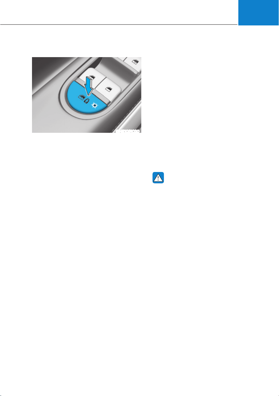
05
5-37
Electronic Child Safety Lock
ONE1051020
When the electronic child safety lock
button is pressed and the indicator
light on the button illuminates, the rear
doors cannot be opened from inside the
vehicle.
ś The rear door window cannot be
opened or closed while the electronic
child safety lock button is in the LOCK
position (indicator light ON).
For more details, refer to “Windows”
section in this chapter.
ś Electronic child safety lock does not
automatically turn on unless the driver
presses the electronic child safety
lock button.
ś If 3 minutes passes after the Start/
Stop button is pressed to the OFF
or ACC, the indicator on the button
turns off, and the driver cannot turn
off electronic child safety lock by
pressing the button. To turn off the
function, press the Start/Stop button
to the ON position, and then press the
electronic child safety lock button.
ś If the power is supplied again after
removing the battery or battery is
discharged while the electronic child
safety lock button is in the LOCK
position, press the button once more
to match the state of the indicator on
the electronic child safety lock button
and actual status of the electronic
child safety lock function.
ś If the airbag is activated while the
electronic child safety lock button
is in the LOCK position (indicator
light ON), the rear doors will unlock
automatically.
ś Vehicles equipped with the electronic
child safety lock feature is not
provided with a manual child safety
lock.
WARNING
If children accidentally opens the rear
door while the vehicle is in motion, they
could fall out of the vehicle. Electronic
child safety lock should always be used
whenever children are in the vehicle.
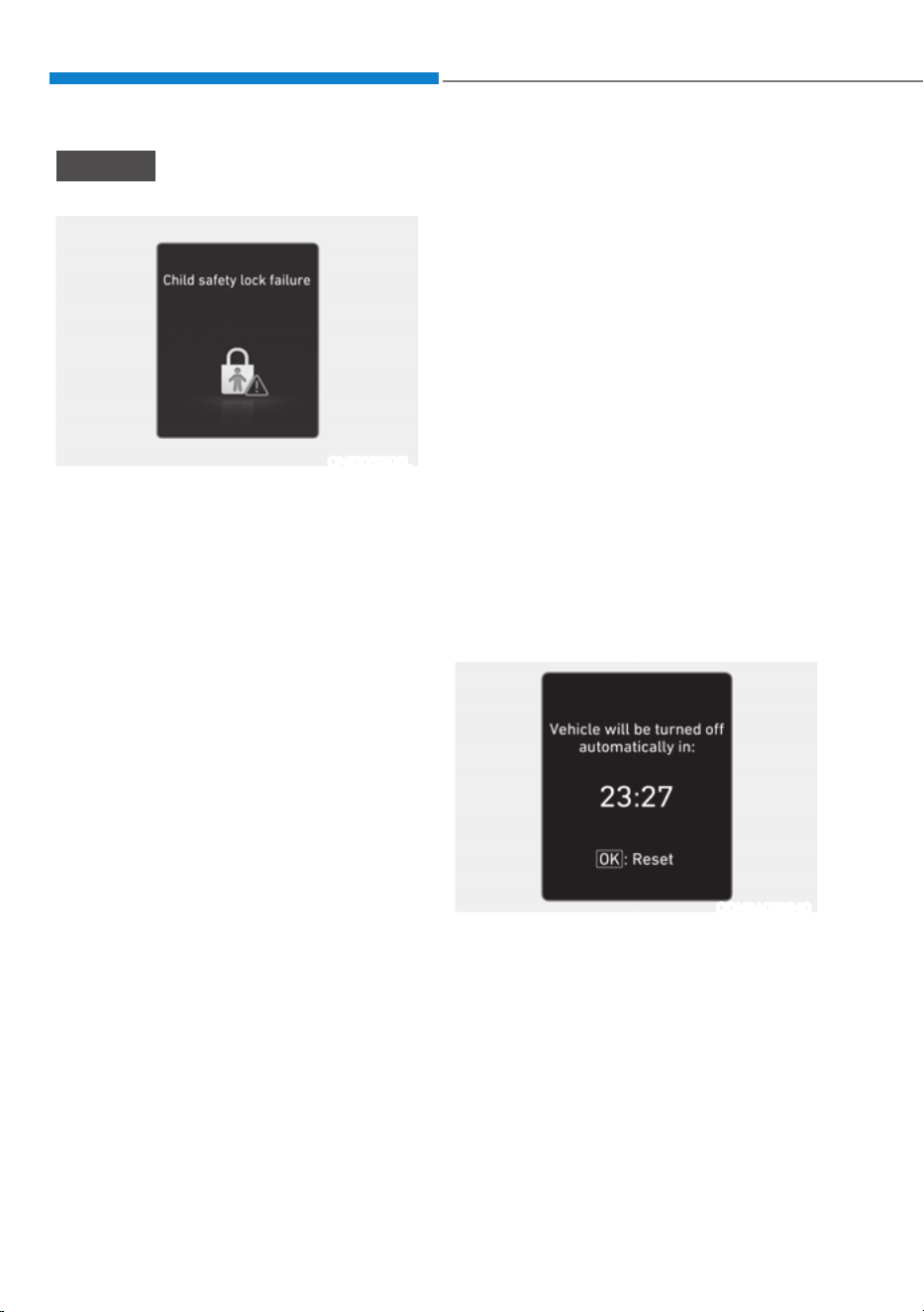
Convenience Features
5-38
NOTICE
Child safety lock failure
ONE1051205L
When electronic child safety lock does
not work even though the button is
pressed, the message will be displayed
and an alarm will sound. If this occurs,
have the vehicle inspected by an
authorized HYUNDAI dealer.
Safe Exit Assist (if equipped with
electronic child safety lock)
Safe Exit Assist helps prevent the rear
occupant from opening the rear door.
When an approaching vehicle from the
rear area is detected after the vehicle
stops, the rear doors will not unlock even
when the driver tries to unlock the rear
doors using the electronic child safety
lock button.
For more details, refer to “Safe Exit
Assist (SEA)” section in chapter 7.
Vehicle Auto-Shut Off Function
If you forget to turn off the vehicle that
EV Drivable for a period of time, Vehicle
Shuts Off automatically to prevent waste
electric power.
Operating Conditions
Vehicle Auto-Shut Off timer activates
when the following conditions are met
ś Not Auto-Shut Off timer reset
condition
- Vehicle is not EV ready state(Only
Ignition On) or the utility mode on
- Gear Shift Other than P
- Stepped on the brake pedal of the
accelerator pedal
- Fastened driver’s seat belt and
passenger’s seat belt
- Passenger`s seat is occupied
- The vehicle moves(vehicle speed is
above 2 mph (3 km/h))
- When Auto-Shut Off timer is left
10minutes, the user setting mode
pops up in the instrument cluster.
And you can check the time left. If
you push the ‘OK’ button, Auto-Shut
off timer is reset.
ODN8A059340
ś Head unit is not updating
ś Outside of vehicle charging connector
engaged or outside V2L used
ś If you want to deactivate auto-shut
off function during inside V2L, use the
Utility mode
System Operation
If the system is satisfied operating
conditions after 90 minutes, vehicle shut
off automatically.

05
5-39
This system helps to protect your vehicle
and valuables. The horn will sound and
the hazard warning lights will blink
continuously if any of the following
occur:
- A door is opened without using the
smart key.
- The liftgate is opened without using
the smart key.
- The vehicle hood is opened.
The alarm continues for 30 seconds, then
the system resets. To turn off the alarm,
unlock the doors with the smart key.
The Theft Alarm System automatically
sets 30 seconds after you lock the
doors and the liftgate. For the system to
activate, you must lock the doors and
the liftgate from outside the vehicle with
the smart key or by touching the touch
sensor or pressing the button on the
outside door handle with the smart key
in your possession.
The hazard warning lights will blink and
the chime will sound once to indicate the
system is armed.
Once the security system is set, opening
any door, the liftgate, or the hood
without using the smart key will cause
the alarm to activate.
The Theft Alarm System will not set if the
hood, the liftgate, or any door is not fully
closed. If the system will not set, check
the hood, the liftgate, or the doors are
fully closed.
Do not attempt to alter this system or
add other devices to it.
Information
ś Do not lock the doors until all
passengers have left the vehicle. If the
remaining passenger leaves the vehicle
when the system is armed, the alarm
will be activated.
ś If the vehicle is not disarmed with the
smart key, open the doors by using the
mechanical key and start the vehicle by
directly pressing the Start/Stop button
with the smart key.
ś If the system is disarmed by unlocking
the vehicle, but neither a door or the
liftgate is opened within 30 seconds, the
doors will relock and the system will
rearm automatically.
7+()7ǘ$/$506<67(0
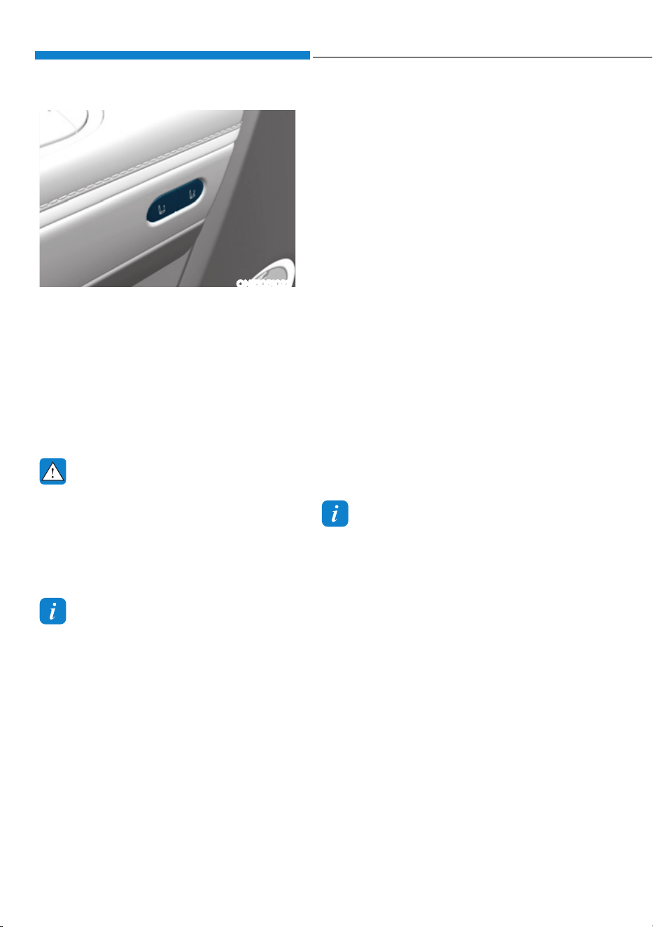
Convenience Features
5-40
,17(*5$7('0(025<6<67(0ǣ,)(48,33('Ǥ
ONE1051023
Integrated Memory System for the
driver’s seat is provided to store and
recall the following memory settings with
a simple button operation.
ś Driver’s seat position
ś Outside rearview mirror position
ś Head-Up Display (HUD) : display
mode, position, AR matching
adjustment (if equipped)
WARNING
Never attempt to operate the
integrated memory system while the
vehicle is moving.
This could result in loss of control, and
an accident causing death, serious
injury, or property damage.
Information
ś If the battery is disconnected, the
memory settings will be erased.
ś If integrated memory system does not
operate normally, have the system
inspected by an authorized HYUNDAI
dealer.
Storing Memory Positions
1. Shift to P (Park) while the Start/Stop
button is in the ON position.
2. Adjust the driver’s seat position,
outside rearview mirror position, and
head-up display height to the desired
position.
3. Hold the button (1 or 2). The system
will beep once and notify you ‘Driver
1 (or 2) settings saved’ will appear on
the infotainment screen.
Recalling Memory Positions
1. Shift to P (Park) while the Start/Stop
button is in the ON position.
2. Press the desired memory button (1
or 2). The system will beep once, and
then the driver’s seat position, outside
rearview mirror position, and head-
up display height will automatically
adjust to the stored positions.
3. ‘Driver 1 (or 2) settings applied’ will
appear on the infotainment screen.
Information
ś In order to adjust the memory button
(2) while adjusting the memory button
(1), press the memory button (1) to
pause the adjustment of (1), then press
memory button (2).
ś If you adjust the seat, rearview mirror,
head-up display while recalling the
stored positions, the manually adjusted
settings will be applied.

05
5-41
Resetting the System
Take the following procedures to reset
integrated memory system, when it does
not operate properly.
Resetting integrated memory
system
1. Stop the vehicle and open the driver’s
door with the Start/Stop button in the
ON position and the vehicle shifted to
P (Park).
2. Adjust the driver’s seat and seatback
to the foremost position.
3. Press the memory button 1 (or 2)
and push forward the driver’s seat
movement switch over 2 seconds
simultaneously.
While resetting integrated memory
system
1. Resetting starts with a notification
sound.
2. The driver’s seat and seatback is
adjusted to the rearward position with
the notification sound.
3. The driver’s seat and seatback is
re-adjusted to the default position
(central position) with the notification
sound.
However, in the following cases, the
resetting procedure and the notification
sound may stop.
ś The memory button is pressed.
ś The seat control switch is operated.
ś The gear is shifted out of P (Park).
ś The driving speed exceeds 3 km/h
(2 mph).
ś The driver’s door is closed.
NOTICE
ś While integrated memory system
is being reset, if the resetting
and notification sound stops
incompletely, restart the resetting
procedure again.
ś Make sure that there is no objects
around the driver’s seat in advance
of resetting the integrated memory
system.
ś After resetting the integrated
memory system, the adjustment for
the driver seat must be stored again
to recall the memory position.

Convenience Features
5-42
Seat Easy Access
Seat easy access will move the driver’s
seat and steering wheel automatically as
follows:
ś Exiting the vehicle:
The driver’s seat will move as follows
when the Start/Stop button is in the
OFF position with the gear in P (Park)
and the driver’s door open.
- Driver seat: Moves rearward
depending on the distance selected
from the Settings menu in the
infotainment system.
However, the driver’s seat may not
move rearward if there is not enough
space between the driver’s seat and
the rear seats.
ś Entering the vehicle:
The driver’s seat will move as follows
when the Start/Stop button is pressed
to the ACC, ON or START position
or while carrying the smart key, the
driver’s door is closed with the Start/
Stop button in the OFF position.
- Driver seat: Moves back to its
original position.
ś You can set the Seat Easy Access
function from the Settings menu
in the infotainment system screen.
Select:
- Driver seat
6HWXSƟ9HKLFOH6HWWLQJVƟ6HDWƟ
6HDWLQJ(DV\$FFHVVƟ'ULYHU6HDW
(DV\$FFHVVƟ1RUPDO([WHQGHG2II
For detailed information, refer to the
separately supplied infotainment
system manual.

05
5-43
0(025<6($7&21),*85$7,216ǣ,)(48,33('Ǥ
Memory seat configurations for the
seats are provided to store and recall the
following memory settings with a simple
operation on the infotainment system.
WARNING
Never attempt to operate the
integrated memory system while the
vehicle is moving.
This could result in loss of control, and
an accident causing death, serious
injury, or property damage.
CAUTION
The function requires a large amount of
electrical power. To prevent the battery
from discharging, refrain from using it
when the vehicle start switch is off.
ś If the battery is disconnected, the
memory settings will be erased.
ś If integrated memory system does
not operate normally, have the
system inspected by an authorized
HYUNDAI dealer.
Storing Memory Positions
ONE1051250L
You can save the position of each seat
on the Infotainment system screen as
below.
1. Shift to P (Park) while the Start/Stop
button is in the ON position.
2. Touch the Memory seat configuration
icon in the infotainment home screen.
3. Adjust the each seat position with
arrow icons to the desired position on
the infotainment screen.
4. To save the each seat that desired
position, touch the ‘Save’ icon.
5. Select the one of the mode on the
infotainment screen. The mode that
selected will be saved.
Recalling Memory Positions
1. Shift to P (Park) while the Start/Stop
button is in the ON position.
2. Touch the desired memory mode icon
(1,2 or 3) and touch ‘Apply’ icon on the
infotainment screen.
3. The seats will automatically adjust to
the stored positions.
4. To stop working while recalling the
saved mode, touch ‘Stop’ icon on the
infotainment screen.

Convenience Features
5-44
STEERING WHEEL
Electric Power Steering (EPS)
The system assists you with steering the
vehicle. If the vehicle is turned off or
if the power steering system becomes
inoperative, you may still steer the
vehicle, but it will require increased
steering effort.
Should you notice any change in the
effort required to steer during normal
vehicle operation, have the system
checked by an authorized HYUNDAI
dealer.
CAUTION
If Electric Power Steering does not
operate normally, the
warning light
and the message ‘Check motor driven
power steering’ will illuminate on the
instrument cluster. You may steer the
vehicle, but it will require increased
steering efforts. Take the vehicle to an
authorized HYUNDAI dealer and have
the system checked as soon as possible.
Information
The following symptoms may occur during
normal vehicle operation:
ś The steering effort may be high
immediately after pressing the Start/
Stop button to the ON position.
This happens as the system performs
WKH(36V\VWHPGLDJQRVWLFV:KHQWKH
diagnostics are completed, the steering
wheel effort will return to its normal
condition.
ś :KHQWKHEDWWHU\YROWDJHLVORZ\RX
might have to put more steering effort.
However, it is a temporary condition so
that it will return to normal condition
after charging the battery.
ś A click noise may be heard from the
(36UHOD\DIWHUWKH6WDUW6WRSEXWWRQLV
in the ON or OFF position.
ś 0RWRUQRLVHPD\EHKHDUGZKHQWKH
vehicle is at a stop or at a low driving
speed.
ś :KHQ\RXRSHUDWHWKHVWHHULQJZKHHO
in low temperatures, abnormal noise
may occur. If the temperature rises, the
noise will disappear. This is a normal
condition.
ś :KHQDQHUURULVGHWHFWHGIURP(36
the steering effort assist function will
not be activated in order to prevent
fatal accidents. Instrument cluster
warning lights may be on or the
steering effort may be high. If these
symptoms occur, drive the vehicle to
a safe area as soon as it is safe to do
so. Have the system checked by an
authorized HYUNDAI dealer as soon
as possible.
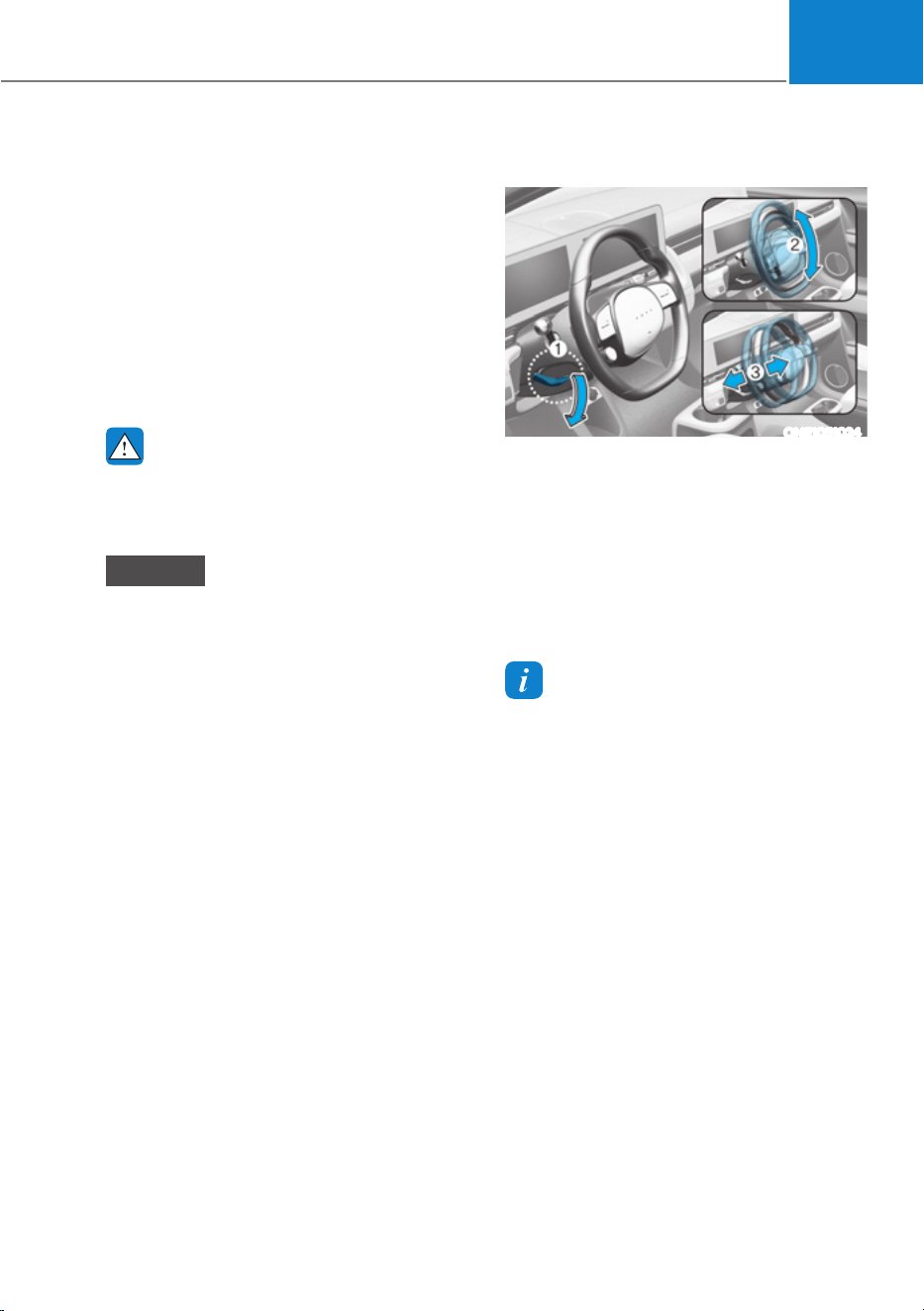
05
5-45
Tilt/Telescopic Steering
When adjusting the steering wheel to a
comfortable position, adjust the steering
wheel so that it points toward your chest,
not toward your face. Make sure you can
see the instrument cluster warning lights
and gauges. After adjusting, push the
steering wheel both up and down to be
certain it is locked in position.
Always adjust the position of the steering
wheel before driving.
WARNING
NEVER adjust the steering wheel while
driving. This may cause loss of vehicle
control resulting in an accident.
NOTICE
While adjusting the steering wheel
height, please do not push or pull it
hard since the fixture can be damaged.
Manual adjustment
ONE1051024
To adjust the steering wheel angle and
height:
1. Pull down the lock-release lever (1).
2. Adjust the steering wheel to the
desired angle (2) and distance
forward/back (3).
3. Pull up the lock-release lever to lock
the steering wheel in place.
Information
Sometimes the lock release lever may not
engage completely. This may occur when
the gears of the locking mechanism do not
completely mesh. If this occurs, pull down
on the lock-release lever, readjust the
steering wheel again, and then pull back
up on the release lever to lock the steering
wheel in place.
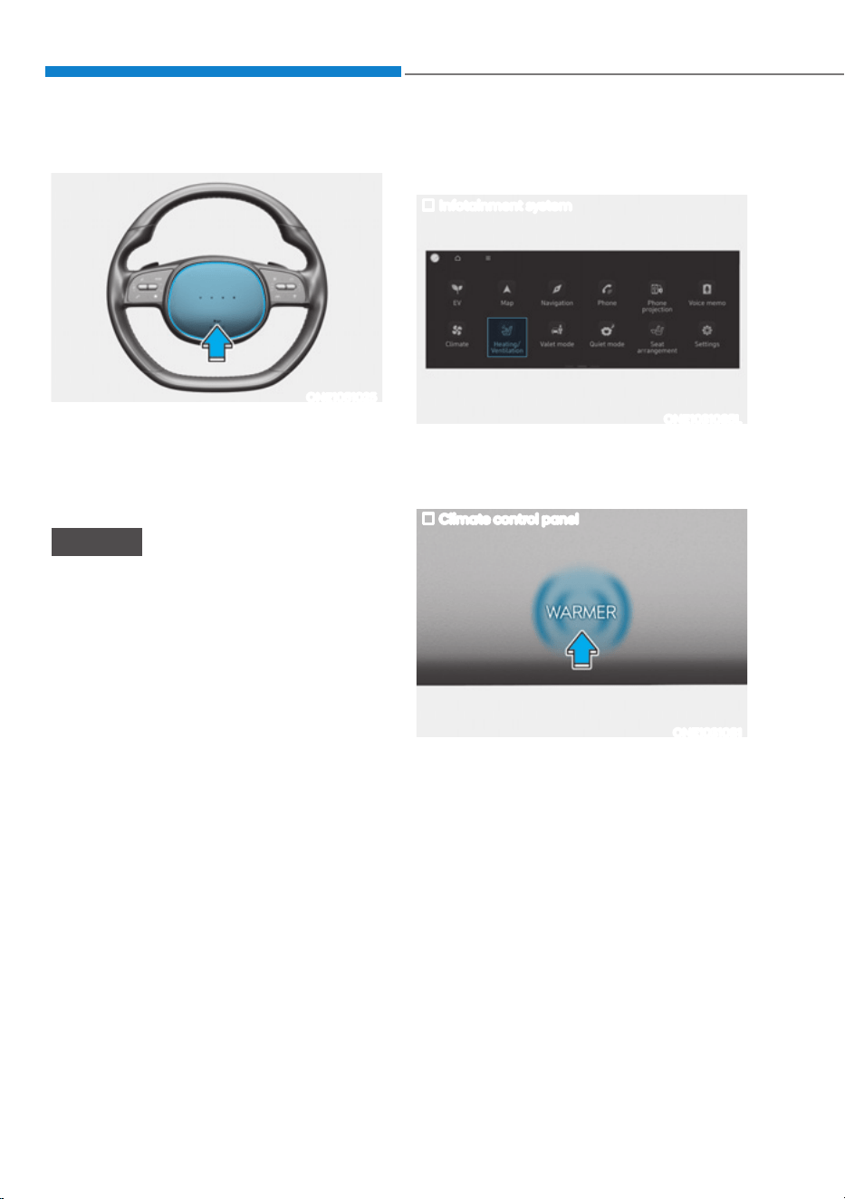
Convenience Features
5-46
Horn
ONE1051025
To sound the horn, press the area
indicated by the horn symbol on your
steering wheel (see illustration). The
horn will operate only when this area is
pressed.
NOTICE
Do not strike the horn severely to
operate it, or hit it with your fist. Do not
press on the horn with a sharp-pointed
object.
Heated Steering Wheel
(if equipped)
Infotainment system
ONE1031085L
While the vehicle is running, touch
Heating/Ventilation icon in the
infotainment home screen.
Climate control panel
ONE1031081
Press WARMER in the front climate
control panel

05
5-47
ONE1051216L
While the vehicle is running, touch the
heated steering wheel icon to warm the
steering wheel.
ś To warm the steering wheel, touch
the heated steering wheel icon in the
Heating/Ventilation seats.
ś Auto. Controls That Use Climate
Control Settings (for driver’s seat)
The heated steering wheel
automatically controls the steering
wheel temperature depending on
the ambient temperature when the
vehicle is running.
To use this function, it must be
enabled from the Settings menu in the
infotainment system screen.
Select:
- 6HWXSƟ9HKLFOH6HWWLQJVƟ6HDWƟ
+HDWHG9HQWLODWHG)HDWXUHVƟ$XWR
Controls That Use Climate Control
6HWWLQJVƟ+HDWHGVWHHULQJZKHHO
For detailed information, refer to the
separately supplied infotainment
system manual.
ś The heated steering wheel defaults
to the OFF position whenever the
Start/Stop button is pressed to
the ON position. However, if the
Auto. Controls That Use Climate
Control Settings function is ON, the
heated steering wheel will turn on
and off depending on the outside
temperature.
NOTICE
Do not install any cover or accessory
on the steering wheel. The cover or
accessory could cause damage to the
heated steering wheel system.
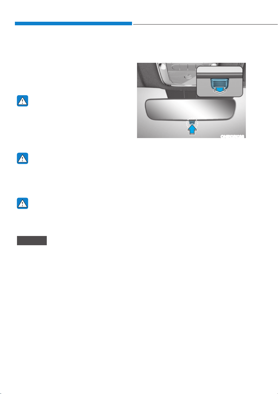
Convenience Features
5-48
0,55256
Inside Rearview Mirror
Before driving your vehicle, check to
see that your inside rearview mirror is
properly positioned. Adjust the rearview
mirror so that the view through the rear
window is properly centered.
WARNING
Make sure your line of sight is not
obstructed. Do not place objects in the
rear seat, cargo area, or behind the rear
head restraints which could interfere
with your vision through the rear
window.
WARNING
To prevent serious injury during an
accident or deployment of the air bag,
do not modify the rearview mirror and
do not install a wide mirror.
WARNING
NEVER adjust the mirror while driving.
This may cause loss of vehicle control
resulting in an accident.
NOTICE
When cleaning the mirror, use a paper
towel or similar material dampened
with glass cleaner. Do not spray glass
cleaner directly on the mirror as this
may cause the liquid cleaner to enter
the mirror housing.
Day/night rearview mirror
(if equipped)
ONE1051026
Make this adjustment before you start
driving and while the day/night lever is in
the day position.
Pull the day/night lever towards you to
reduce glare from the headlamps of the
vehicles behind you during night driving.
Remember that you lose some rearview
clarity in the night position.
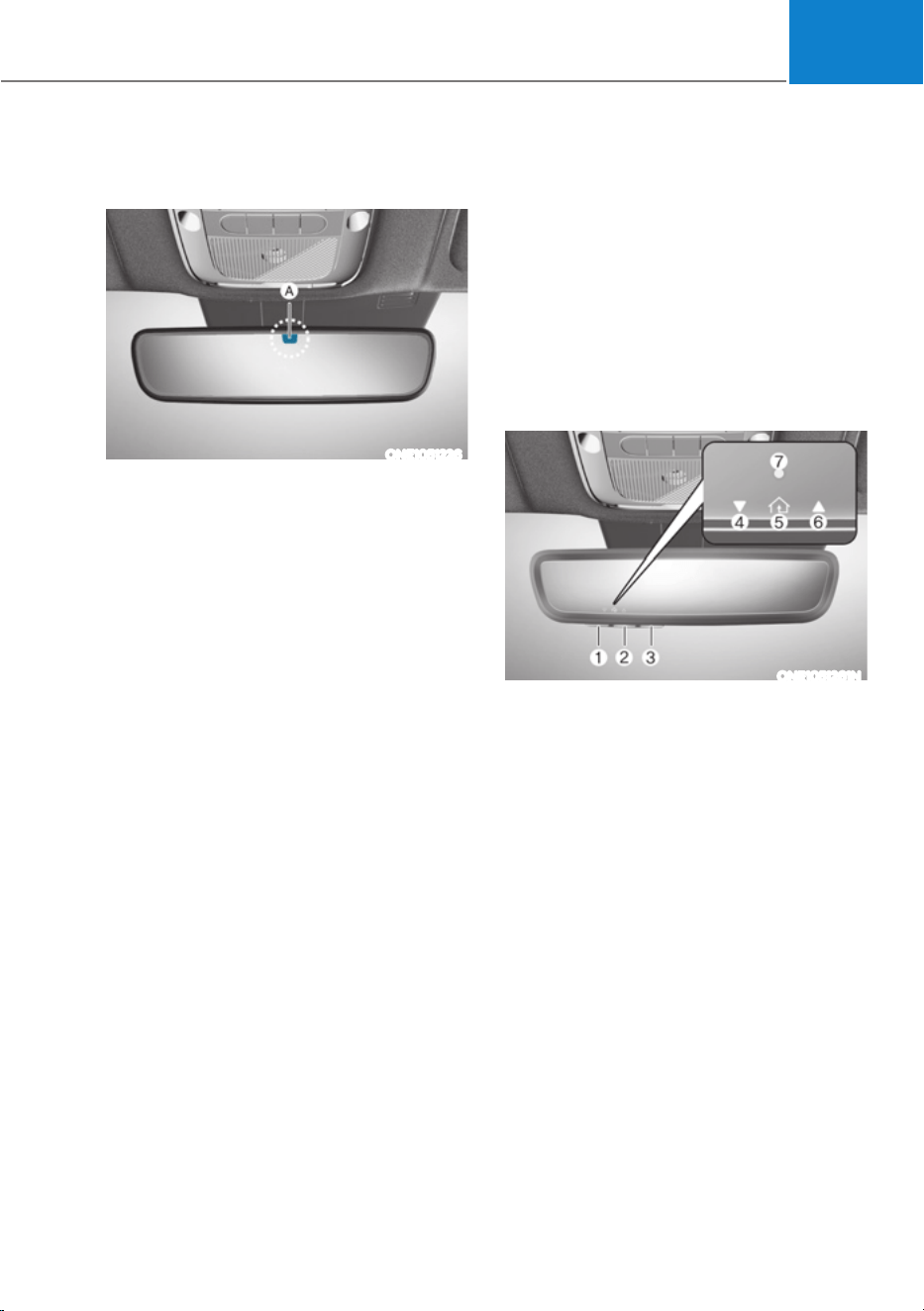
05
5-49
Electric Chromic Mirror (ECM)
(if equipped)
ONE1051226
[A] : Indicator
Some vehicles come equipped with an
electrochromic mirror that helps control
glare while driving at night or under low
light driving conditions.
When the vehicle is running, the glare is
automatically controlled by the sensor
mounted in the rearview mirror. The
sensor detects the light level around the
vehicle, and automatically adjusts to
control the headlamp glare from vehicles
behind you.
Whenever the the gear is shifted to R
(Reverse), the mirror will automatically
go to the brightest setting in order to
improve the driver’s view behind the
vehicle.
Electrochromic mirror (ECM) with
HomeLink® system (if equipped)
Your vehicle may be equipped with
a Gentex Automatic-Dimming Mirror
with an Integrated HomeLink® Wireless
Control System.
During nighttime driving, this feature
will automatically detect and reduce
rearview mirror glare. The HomeLink®
Universal Transceiver allows you to
activate your garage door(s), electric
gate, home lighting, etc.
ONE1051261N
(1) HomeLink Channel 1
(2) HomeLink Channel 2
(3) HomeLink Channel 3
(4) Garage Door Opener Status Indicator :
Closing or Closed
(5) HomeLink Operation Indicator
(6) Garage Door Opener Status Indicator :
Opening or Opened
(7) HomeLink User Interface Indicator

Convenience Features
5-50
$XWRPDWLF'LPPLQJ1LJKW9LVLRQ6DIHW\
196
®
0LUURULIHTXLSSHG
The NVS® Mirror automatically reduces
glare by monitoring light levels in the
front and the rear of the vehicle. Any
object that obstructs either light sensor
will degrade the automatic dimming
control feature.
For more information regarding NVS®
mirrors and other applications, please
refer to the Gentex website:
www.gentex.com
Your mirror will automatically dim
upon detecting glare from the vehicles
traveling behind you.
The mirror defaults to the ON position
each time the vehicle is started.
Integrated HomeLink
®
:LUHOHVV&RQWURO
System
The HomeLink® Wireless Control System
provides a convenient way to replace
up to three hand held radio-frequency
transmitters used to activate compatible
devices such as gate operators, garage
door openers, entry door locks, security
systems, and home lighting.
NOTICE
HomeLink® operates while the ignition
switch is in the ACC or ON position
for safety reasons. It is to prevent
unintentional security problems from
happening when the vehicle is parked
outside the garage.
WARNING
Before programming HomeLink® to a
garage door opener or gate operator,
make sure people and objects are out
of the way of the device to prevent
potential harm or damage. Do not
use the HomeLink® with any garage
door opener that lacks the safety
stop and reverse features required
by U.S. federal safety standards (this
includes any garage door opener model
manufactured before April 1, 1982).
A garage door that cannot detect an
object - signaling the door to stop and
reverse - does not meet current U.S.
federal safety standards. Using a garage
door opener without these features
increases the risk of serious injury or
death.
For more information, contact
HomeLink® at www.homelink.com, or
call Home-Link customer support at
1-800-355-3515.
It is also recommended that a new
battery be replaced in the handheld
transmitter of the device being trained
to HomeLink® for quicker training and
accurate transmission of the radio
frequency.
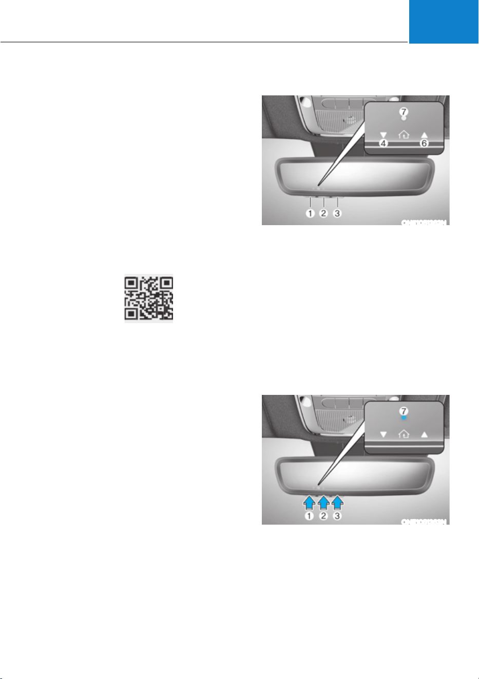
05
5-51
3URJUDPPLQJ+RPH/LQN
®
The following steps show how to
program HomeLink. If you have any
questions or are having difficulty
programming your HomeLink buttons,
refer to the HomeLink website or call the
HomeLink customer support toll-free
number. Do this, before going back to
the dealer who sold you the car.
ś Visit the HomeLink website at: www.
homelink.com. Then at the top of the
page, choose your vehicle make. Then
watch the You Tube video, and/or
access additional website information.
ś If you choose to access the website
via your cell phone, scan the QR code.
ś Or, call HomeLink customer support
at 1-800-355-3515 (Please have the
vehicle make/model AND the opener
device make/model readily available.)
1) Programming Preparation
ONE1051262N
1. When programming a garage door
opener, it is advised to park the
vehicle outside of the garage.
2. It is recommended that a new battery
be placed in the handheld transmitter
of the device being programmed to
HomeLink for quicker training and
accurate transmission of the radio-
frequency signal.
3. Place the ignition switch to the ACC
(Accessory) position for programming
of HomeLink.
2) Programming a New HomeLink®
ONE1051263N
1. Press and release the HomeLink
button (1), (2) or (3), you would like
to program. The HomeLink indicator
light (7) will flash orange slowly (if
not, perform the steps of “Erasing
HomeLink Buttons” section, and start
over).
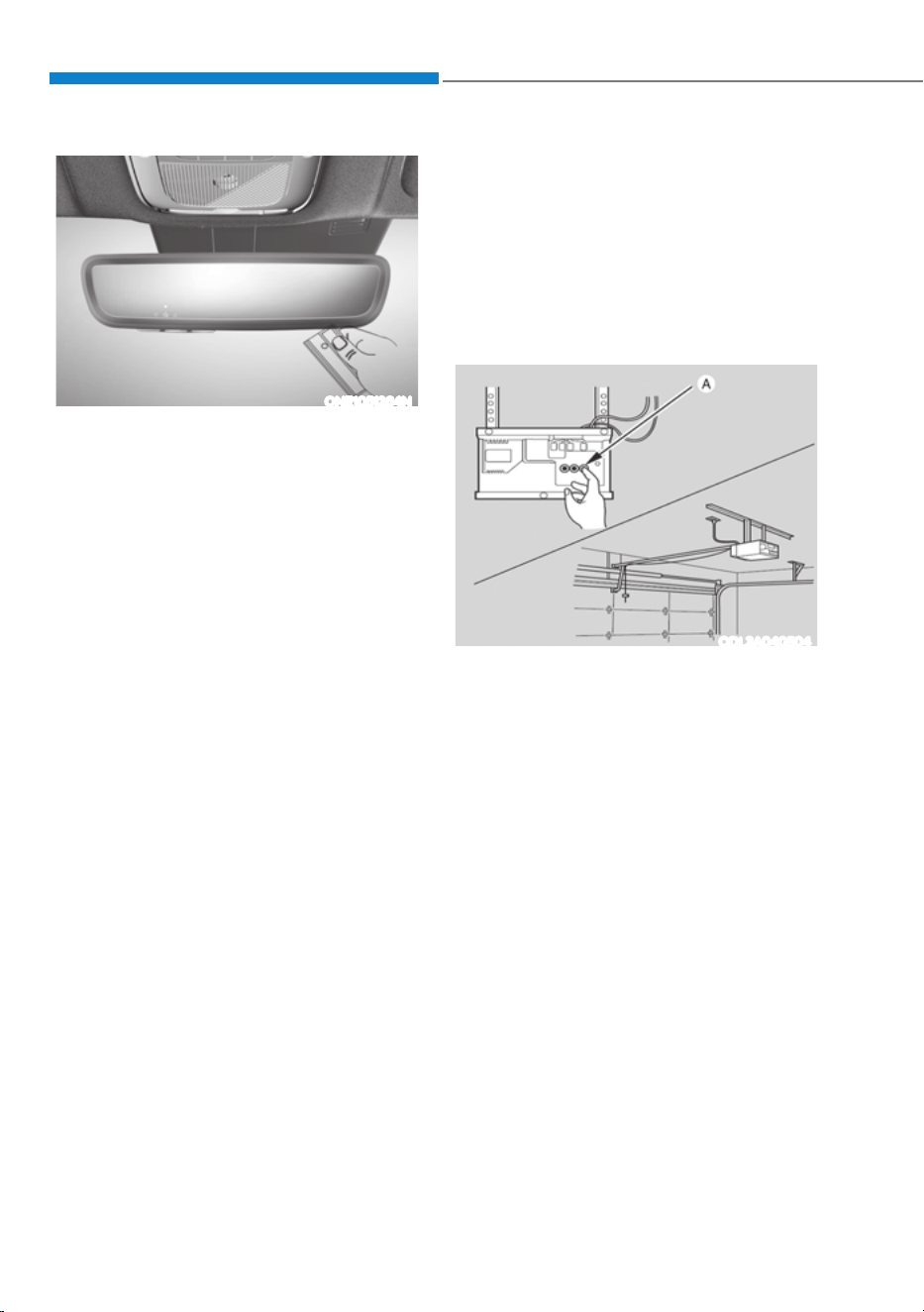
Convenience Features
5-52
ONE1051264N
2. Position the garage door opener
remote 1 – 3 inches (2 – 8cm) away
from the HomeLink buttons.
3. While the HomeLink indicator light (7)
is flashing orange, press and hold the
hand-held remote button. Continue
pressing the handheld remote button
until the HomeLink indicator light (7)
light changes from orange to green.
You may now release the handheld
remote button.
4. Wait until your garage door comes
to a complete stop, regardless of
position, before proceeding to the
next steps.
5. Press and release the HomeLink
button you are programming and
observe the indicator light.
śIf the indicator light remains solid
green, your device should operate
when the HomeLink button is
pressed. At this point, if your device
operates, programming is complete.
śIf the indicator light rapidly
flashes green, firmly press, hold
for two seconds and release the
HomeLink button up to three times
in a row slowly to complete the
programming process. Do not press
the HomeLink button rapidly. At
this point if your device operates,
programming is complete. If the
device does not operate, continue
with step 6.
6. At the garage door opener motor,
(security gate motor, etc.) locate the
“Learn”, “Smart”, “Set” or “Program”
button. This can usually be found
where the hanging antenna wire is
attached to the motor-head unit (see
the device’s manual to identify this
button). The name and color of the
button may vary by manufacturer.
ODL3A040504
à A ladder and/or second person may
simplify the following steps.
7. Firmly press and release the “Learn”,
“Smart”, “Set” or “Program” button.
You now have up to 30 seconds in
which to complete the next step.
8. Return to the vehicle and firmly press,
hold for two seconds and release,
the HomeLink button up to three
times in a row slowly. Do not press
the HomeLink button rapidly. As soon
as you see the garage door start to
move, stop pressing any buttons
until a few seconds after the garage
door has come to a complete stop,
regardless of position. At this point,
programming is complete and your
device should operate when the
HomeLink button is pressed and
released.

05
5-53
3) Two-Way Communication
Programming (For select garage
door openers)
If your garage door opener has the
‘myQ’ logo on its side, your opener
likely has Two-Way Communication
capability. HomeLink has the capability
to establish Two-Way Communication
with your garage door opener. HomeLink
can receive and display “closing”
or “opening” status messages from
compatible garage door openers. At
any time, Home-Link can also recall
and display the last recorded status
communicated by the garage door
opener to indicate your garage door
being “closed” or “opened”.
To check if your garage door opener is
compatible with this feature, refer to
www.homelink.com/compatible/Two-
way-Communication. If your garage
door opener has this functionality, AND
the Two-Way Communication indicators
(4), (6) in the mirror appear while the
garage door is opening/closing, then
no further steps are needed. Two-Way
Communication Programming is already
complete. However, if your garage door
opener has this functionality, AND the
Two-Way Communication indicators (4),
(6) in the mirror DO NOT appear while
the garage door is opening/closing, use
the following instructions to enable this
functionality.
1. In your vehicle, press and hold the
programmed HomeLink button for 2
seconds, then release. Confirm that
the garage door is moving. AFTER it
stops, you will have one minute to
complete the following steps:
à A ladder and/or second person may
simplify the following steps.
2. On your garage door opener in your
garage, locate the “Learn” button
(usually near where the hanging
antenna wire is attached to the garage
door opener). If there is difficulty
locating this button, reference the
device’s owner’s manual.
3. Press and release the “Learn” button.
4. A light on your garage door opener
may flash, and your Two-Way
Communication indicators (4), (6) in
your vehicle may flash, confirming
completion of the process.
5. Return to the vehicle and firmly
press and release the programmed
HomeLink button to activate
your garage door. The Two-Way
Communication indicators (4), (6)
flash in orange when the door is
moving. Do not make any additional
button presses until AFTER the garage
door has come to a complete stop.
6. Your Two-Way Communication
programming is now complete.
Information
If your garage door opener has Two-
:D\&RPPXQLFDWLRQIXQFWLRQDOLW\
it is possible for HomeLink to stop
functioning the garage door shortly
after initial programming, IF the Two-
:D\&RPPXQLFDWLRQ3URJUDPPLQJ
wasn’t properly completed. This
usually happens after the first 10 times
a programmed HomeLink button is
pressed. If you experience this, completing
WKH³3URJUDPPLQJD1HZ+RPH/LQN
%XWWRQ´DQG³7ZR:D\&RPPXQLFDWLRQ
3URJUDPPLQJ´ZLOOUHVWRUHGRRU
operation.
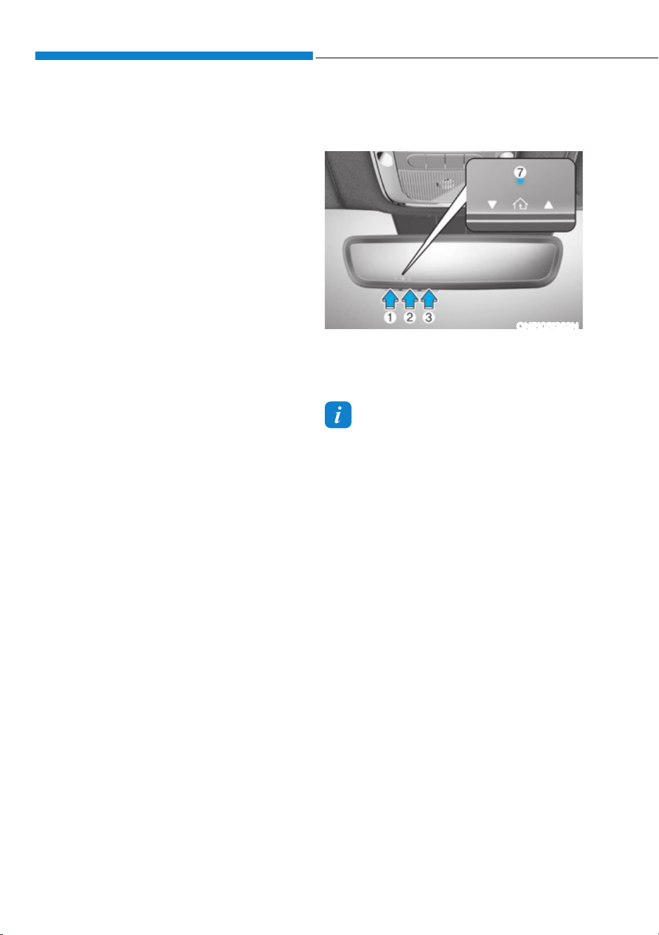
Convenience Features
5-54
4) Canadian Programming
Canadian radio-frequency laws require
transmitter remote signals to “time-
out” (or quit) after a couple seconds of
transmission, which may not be long
enough for HomeLink to pick up the
signal during programming.
If you live in Canada or you are having
difficulties programming a gate operator
or garage door opener by using the
programming procedures, replace
“Programming a New HomeLink Button”
step 3 with the following:
While the HomeLink indicator light (7)
is flashing orange, press and release
(“cycle”) your device’s handheld remote
every two seconds until the HomeLink
indicator light (7) changes from orange
to green. You may now release the hand-
held remote button. Then proceed with
“Programming a New HomeLink Button”
step 4.
2. Operating HomeLink
®
1) Operating HomeLink®
ONE1051263N
1. Press and release the desired
programmed HomeLink button (1, 2
or 3).
Information
The HomeLink indicator (7) should
light green, solid or flashing, and your
programmed device should operate.
If your device does not operate, the
HomeLink programming was not
successful, and you’ll need to reprogram
the button.
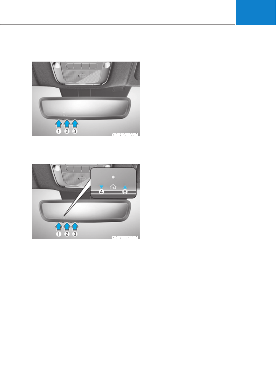
05
5-55
2) Two-Way Communication Display
Behavior
ONE1051265N
1. Press and release one of the
programmed HomeLink buttons (1, 2
or 3).
ONE1051266N
2. The indicator (4) and (6) operates as
below, if your garage door opener
has Two-Way Communication
functionality.
ś If the indicator (4) flashes in Orange,
it indicates that the garage door is
“Closing”.
ś The indicator (4) turns solid green
once the garage door has closed.
ś If the indicator (6) flashes in Orange,
it indicates that the garage door is
“Opening”.
ś The indicator (6) turns solid green
once the garage door has fully
opened.
ś If the indicator (4) or (6) does not
turn to green, it indicates that the
last status of garage door was not
received properly. The HomeLink
mirror tries to receive the last known
status of the garage door for a few
seconds.
3) Recalling Garage Door Status
HomeLink mirror with Two-Way
Communication provides a way to view
the last stored message from the garage
door opener. In order to recall the last
known status of the last activated device,
press the buttons “1 and 2” OR “2 and 3”
simultaneously.
ś If the indicator (4) appears solid
Green, it indicates that the last
activated device was “closed”
properly.
ś If the indicator (6) appears solid
Green, it indicates that the last
activated device was “open” properly.
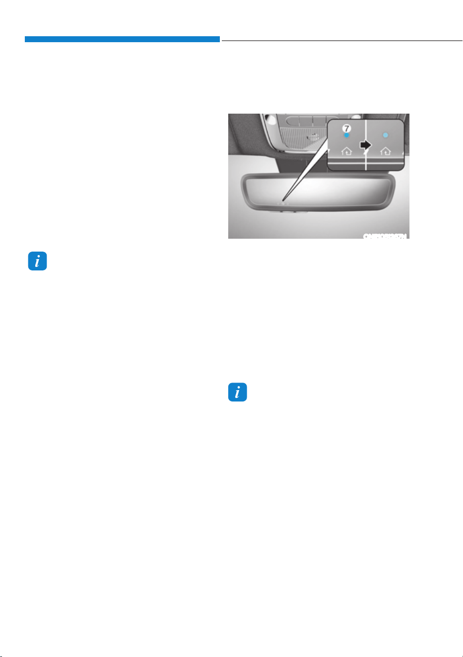
Convenience Features
5-56
3. Erasing HomeLink
®
Buttons
1) Erasing and Reprogramming a
Single HomeLink® Button:
1. Press and hold the desired HomeLink
button you want to re-program. DO
NOT release the button.
2. The HomeLink indicator light (7) will
illuminate solid green. Release the
button as soon as the HomeLink
indicator light (7) begins to flash
orange, usually about 20 seconds.
3. Proceed with the steps in the
“Programming a New HomeLink
Button” section.
Information
If you do not complete the re-
programming of a new device to the
button, it will revert to the previously
stored programming.
2) The following instructions will erase
ALL HomeLink® programming from
ALL buttons:
ONE1051267N
1. Press and hold the buttons (1) and (3)
simultaneously
2. The HomeLink indicator light (7) will
illuminate solid Orange for about 10
seconds
3. Release the buttons once the
HomeLink indicator light (7) changes
to Green and flashes rapidly
4. Now all three HomeLink buttons
(1), (2) and (3) are cleared of any
programming
Information
HomeLink
®
and the HomeLink
®
House
logo are registered trademarks of Gentex
Corporation.
The myQ logo is a registered trademark of
The Chamberlain Group, Inc.

05
5-57
FCC (USA) and ISED (Canada)
This device complies with FCC rules
part 15 and Innovation, Science, and
Economic Development Canada RSS-
210. Operation is subject to the following
two conditions: (1) This device may not
cause harmful interference, and (2) This
device must accept any interference that
may be received including interference
that may cause undesired operation.
WARNING: The transmitter has been
tested and complies with FCC and
ISED rules. Changes or modifications
not expressly approved by the party
responsible for compliance could void
the user’s authority to operate the
device.
This equipment complies with FCC
and ISED radiation exposure limits set
forth for an uncontrolled environment.
End Users must follow the specific
operating instructions for satisfying RF
exposure compliance. This transmitter
must be at least 20cm from the user and
must not be co-located or operating in
conjunction with any other antenna or
transmitter.
Cet appareil est conforme aux
règlements de la FCC, section 15, et
au CNR-210 d’Innovation, Sciences et
Dhveloppement économique Canada. Le
fonctionnement est assujetti aux deux
conditions suivantes : (1) cet appareil ne
doit pas causer d’interférences nuisibles
et (2) cet appareil doit accepter toute
interférence reçue, y compris celle qui
pourrait entraîner un dysfonctionnement.
MISE EN GARDE : L’émetteur a subi des
tests et est conforme aux règlements
de la FCC et d’ISDE. Les changements
ou modifications non approuvés
explicitement par la partie responsable
de la conformité pourraient rendre
caduque l’autorisation de l’utilisateur de
se servir du dispositif.
Cet appareil est conforme aux limites
d’exposition aux radiations de la FCC et
d’ISDE établies pour un environnement
non contrôlé. Les utilisateurs finaux
doivent respecter les instructions
d’utilisation spécifiques pour satisfaire
aux exigences de conformité aux
expositions de RF. L’émetteur doit
se trouver à 20 cm au minimum de
l’utilisateur et ne doit pas être situé au
même endroit que tout autre émetteur
ou antenne ni fonctionner avec un autre
émetteur ou antenne.
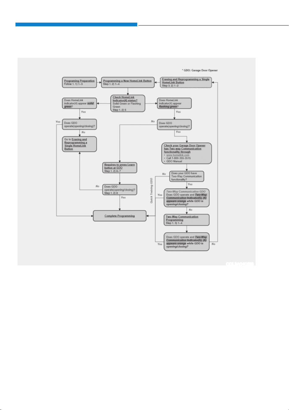
Convenience Features
5-58
+RPH/LQN3URJUDPLQJ)ORZ&KDUW
ODL3A040518
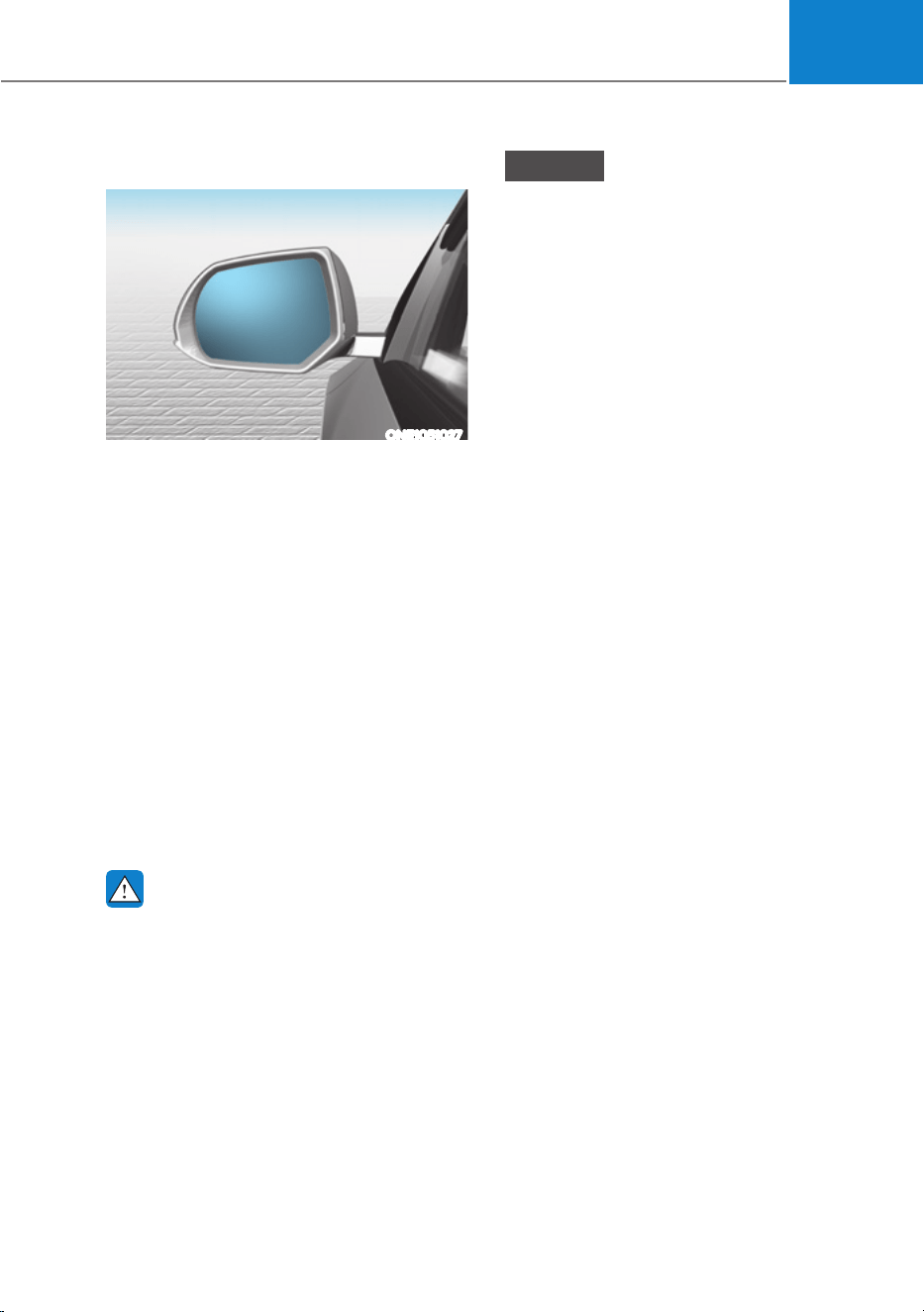
05
5-59
Side View Mirrors
ONE1051027
Your vehicle is equipped with both left-
hand and right-hand sideview mirrors.
The mirrors can be adjusted remotely
with the mirror adjustment control
switch. The sideview mirrors can be
folded to help prevent damage when
going through an automatic car wash or
when passing through a narrow street.
The right sideview mirror is convex.
Objects seen in the mirror are closer than
they appear.
Use the inside side view mirror or look
back directly to determine the actual
distance of other vehicles prior to
changing lanes.
Make sure to adjust the sideview mirrors
to your desired position before you begin
driving.
WARNING
Do not adjust or fold the sideview
mirrors while driving. This may cause
loss of vehicle control resulting in an
accident.
NOTICE
ś Do not scrape ice off the mirror face;
this may damage the surface of the
glass.
ś If the mirror is jammed with ice, do
not adjust the mirror by force. Use
an approved de-icer (not radiator
antifreeze) spray, or a sponge or soft
cloth with very warm water, or move
the vehicle to a warm place and
allow the ice to melt.
ś Do not clean the mirror with harsh
abrasives, fuel or other petroleum
based cleaning products.
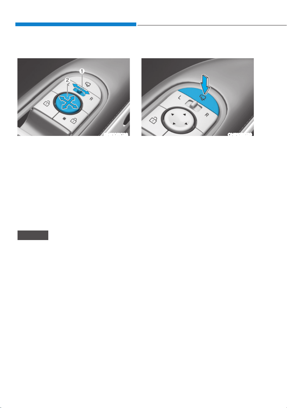
Convenience Features
5-60
Adjusting the rearview mirrors
ONE1051028
Adjusting the rearview mirrors:
1. When the START/STOP button is in
the ACC, ON or START position, press
either the L (Left side) or R (Right side)
button (1) to select the rearview mirror
you would like to adjust.
2. Use the mirror adjustment control
switch (2) to position the selected
mirror up, down, left or right.
3. After adjustment, move the lever (1)
to the middle to prevent inadvertent
adjustment.
NOTICE
ś The mirrors stop moving when
they reach the maximum adjusting
angles, but the motor continues to
operate while the switch is pressed.
Do not press the switch longer than
necessary, because this can damage
the motor.
ś Do not attempt to adjust the
rearview mirrors by hand, because
this can damage the motor.
Folding the rearview mirrors
ONE1051029
Folding button
The rearview mirrors can be folded or
unfolded by pressing the button.
Infotainment system setting
ś Enable on door unlock
,Iœ6HWXSƟ9HKLFOH6HWWLQJVƟ:HOFRPH
0LUURUƟ(QDEOHRQ'RRU8QORFNŔLV
selected from the Settings menu in
the infotainment system screen,
- The mirror will fold or unfold when
the door is locked or unlocked by
the smart key.
- The mirror will fold or unfold when
the door is locked or unlocked by
the touch sensor or button on the
outside door handle.
ś Enable on driver approach
,Iœ6HWXSƟ9HKLFOH6HWWLQJVƟ
&RQYHQLHQFHƟ:HOFRPH0LUURU
Ɵ(QDEOHRQ'ULYHU$SSURDFKŔLV
selected from the Settings menu in
the infotainment system screen, the
mirror will unfold when the vehicle
is approached with the smart key in
possession.
For detailed information, refer to the
separately supplied infotainment
system manual.
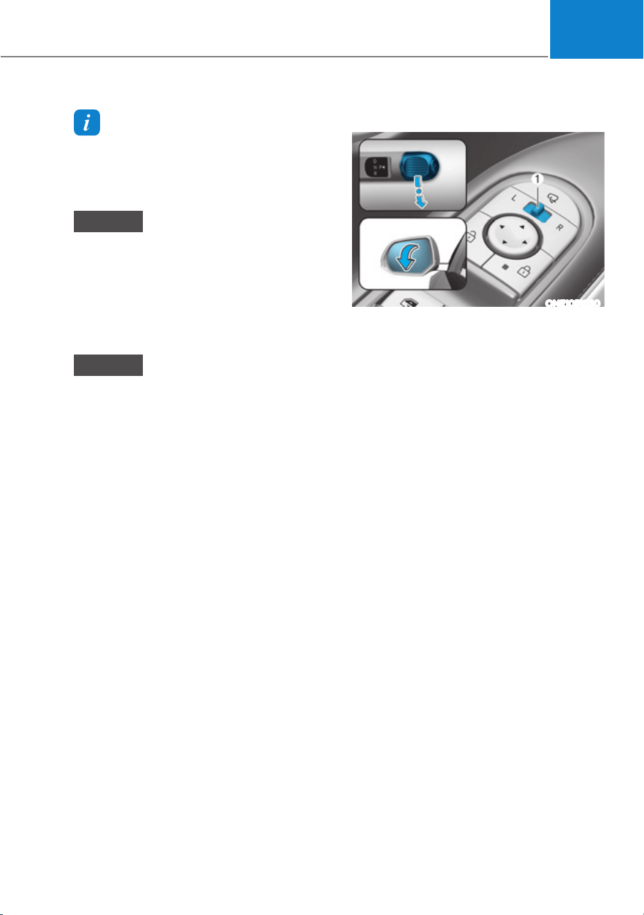
05
5-61
Information
For your safety, the side view mirrors
cannot be folded automatically when
driving at a speed of 9 mph (15 km/h) or
faster.
NOTICE
The electric type side view mirror
operates even though the Start/Stop
button is in the OFF position. However,
to prevent unnecessary battery
discharge, do not adjust the mirrors
longer than necessary while the vehicle
is not running.
NOTICE
Do not fold the electric type side view
mirror by hand. It could cause motor
failure.
Reverse Parking Aid (if equipped)
ONE1051030
When the gear is shifted to the R
(Reverse) position, the side view lever(s)
will rotate downwards to aid with driving
in reverse.
The state of the side view mirror lever (1)
determines whether or not the mirrors
will move:
How it works
ś Left/Right : When either the L (Left) or
R (Right) lever is selected, both side
view mirrors will move.
ś Neutral : When neither switch is
selected, the side view mirrors will not
move.
The side view mirrors will automatically
revert to their original positions if any of
the following occur:
ś The Start/Stop button is pressed to
either the OFF position or the ACC
position.
ś The gear is shifted to any position
except R (Reverse).
ś The side view mirror adjustment
button is not selected.

Convenience Features
5-62
Reverse parking aid user settings
mode
You may change the angle of the side
view mirror if it is difficult to see the rear
view with the basic downward mirror
angle provided when reversing.
When the vehicle is first delivered, the
set downward angle of the left and right
side view mirror are different to ensure
driver visibility.
1. Make sure the vehicle is stopped.
2. Depress the brake pedal and shift
the gear to R (Reverse). When L (Left)
or R (Right) button is pressed, both
side view mirror angle will move
downward to the basic set position.
3. Press either L or R button to select
the side view mirror you would like
to adjust. Then press “ź, Ÿ, Ż, Ź”
switch to adjust the side view mirror
to the desired angle.
4. After adjusting the angle to save the
adjusted side view mirror angle, shift
the gear to another position other
than R (Reverse), or change the L and
R buttons to the neutral position (L
and R buttons are not pressed).
5. Set the other side view mirror
following the above procedure 1 to 4.
Resetting reverse parking aid user settings
mode
To change the side view mirror angle
back to the basic angle, shift the gear to
R (Reverse), and adjust the mirror angle
higher than when the gear is in P (Park),
N (Neutral) and D (Drive).
NOTICE
When changing the angle of both side
view mirrors, it is recommended to
change the angle one side at a time
following the procedure 1 to 4.
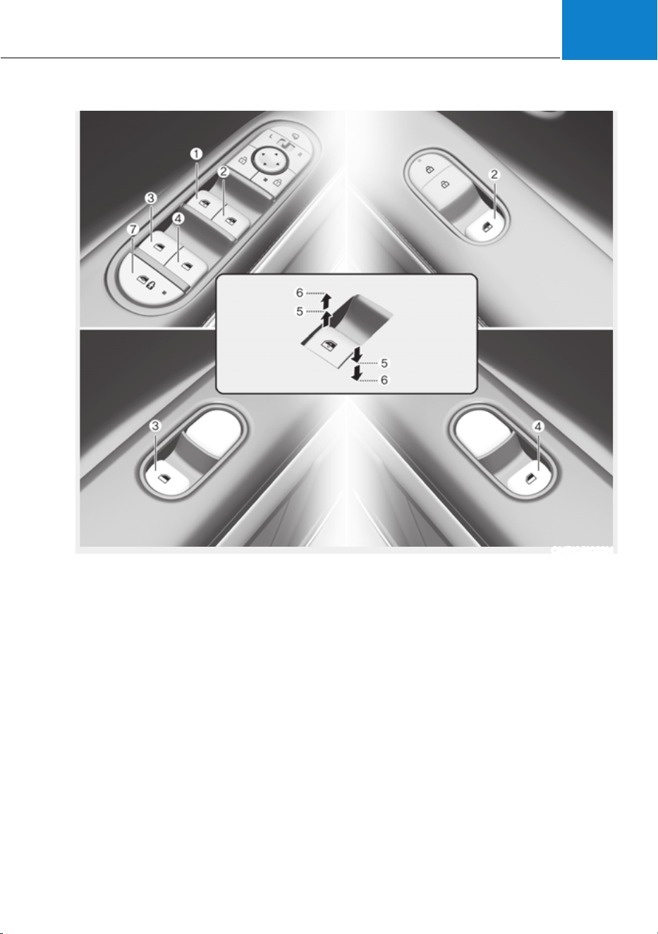
05
5-63
ONE1051032N
WINDOWS
(1) Driver’s door power window switch
(2) Front passenger’s door power
window switch
(3) Rear door (left) power window switch
(4) Rear door (right) power window
switch
(5) Window opening and closing
(6) Automatic power window
(7) Power window lock switch
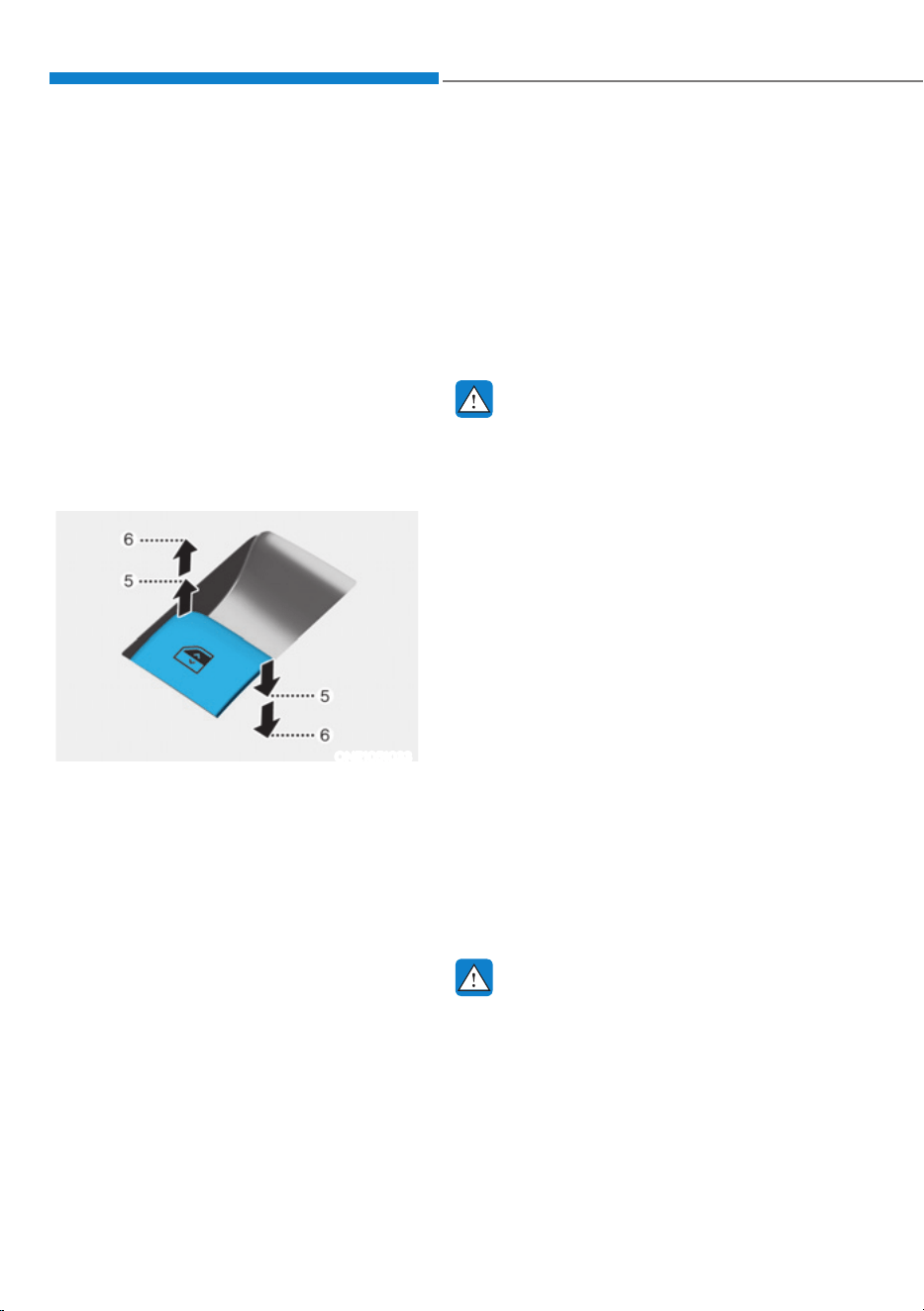
Convenience Features
5-64
Power Windows
The Start/Stop button must be in the
ON position to be able to raise or lower
the windows. Each door has a Power
Window switch to control that door’s
window. The driver has a Power Window
Lock button which can block the
operation of rear passenger windows.
The power windows will operate for
approximately 3 minutes after the
Start/Stop button is in the ACC or OFF
position. However, if the front doors are
opened, the Power Windows will not
operate even within the 3 minute period.
Window opening and closing
ONE1051033
To open:
Press the window switch down to the
first detent position (5). Release the
switch when you want the window to
stop.
To close:
Pull the window switch up to the first
detent position (5). Release the window
switch when you want the window to
stop.
Auto up/down window
Pressing the power window switch
momentarily to the second detent
position (6) completely lowers or lifts
the window even when the switch is
released. To stop the window at the
desired position while the window is in
operation, pull up or press down and
release the switch.
WARNING
ś Do not leave the vehicle running
and the key in your vehicle with
unsupervised children. Unattended
children could operate the window,
which could result in serious injury.
ś Do not extend your head, arms or any
other body parts or objects outside
the window while driving to avoid
serious injury.
Resetting the power windows
If the power windows do not operate
normally, the automatic power window
system must be reset as follows:
1. Press the Start/Stop button to the ON
position.
2. Close the window and continue
pulling up on the power window
switch for at least one second.
If the power windows do not operate
properly after resetting, have the system
inspected by an authorized HYUNDAI
dealer.
WARNING
The automatic reverse feature doesn’t
activate while resetting the power
window system.Make sure body parts
or other objects are safely out of the
way before closing the windows to
avoid injuries or vehicle damage.
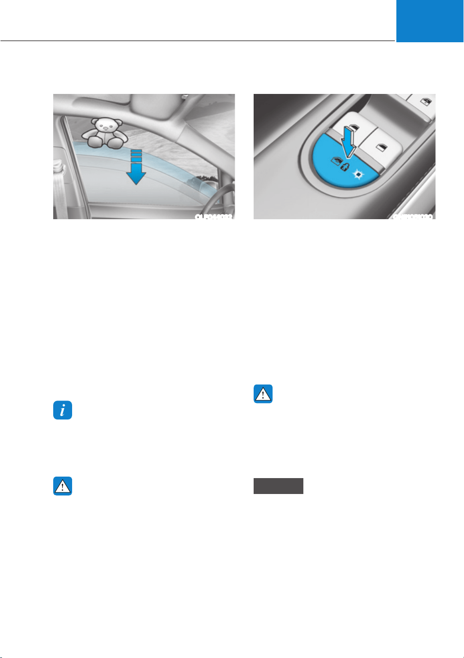
05
5-65
Automatic reverse
OLF044032
If a window senses any obstacle while it
is closing automatically, it will stop and
lower approximately 12 in. (30 cm) to
allow the object to be cleared.
If the window detects the resistance
while the power window switch is
pulled up continuously, the window
will stop upward movement then lower
approximately 1 in. (2.5 cm).
If the power window switch is pulled
up continuously again within 5 seconds
after the window is lowered by the
automatic window reverse feature,
the automatic window reverse will not
operate.
Information
The automatic reverse feature is only
DFWLYHZKHQWKH³$XWR8S´IHDWXUHLVXVHG
by fully pulling up the switch to the second
detent.
WARNING
Make sure body parts or other objects
are safely out of the way before closing
the windows to avoid injuries or vehicle
damage.
Objects less than 0.16 in. (4 mm) in
diameter caught between the window
glass and the upper window channel
may not be detected by the automatic
reverse window and the window will
not stop and reverse direction.
Power window lock button
ONE1051020
The driver can disable the power window
switches on the rear passenger doors by
pressing the power window lock button.
When the power window lock button is
pressed:
ś The rear passenger control will not
be able to operate the rear passenger
power window.
ś Note that the front passenger control
is still able to operate the front
passenger window, and that the driver
master control can still operate all the
power windows.
WARNING
Do not allow children to play with the
power windows. Keep the driver’s
door power window lock button in the
LOCK position. Serious injury or death
can result from unintentional window
operation by a child.
NOTICE
ś To prevent possible damage to the
power window system, do not open
or close two windows or more at the
same time. This will also ensure the
longevity of the fuse.
ś Never try to operate the main
switch on the driver’s door and the
individual door window switch in
opposite directions at the same time.
If this is done, the window will stop
and cannot be opened or closed.
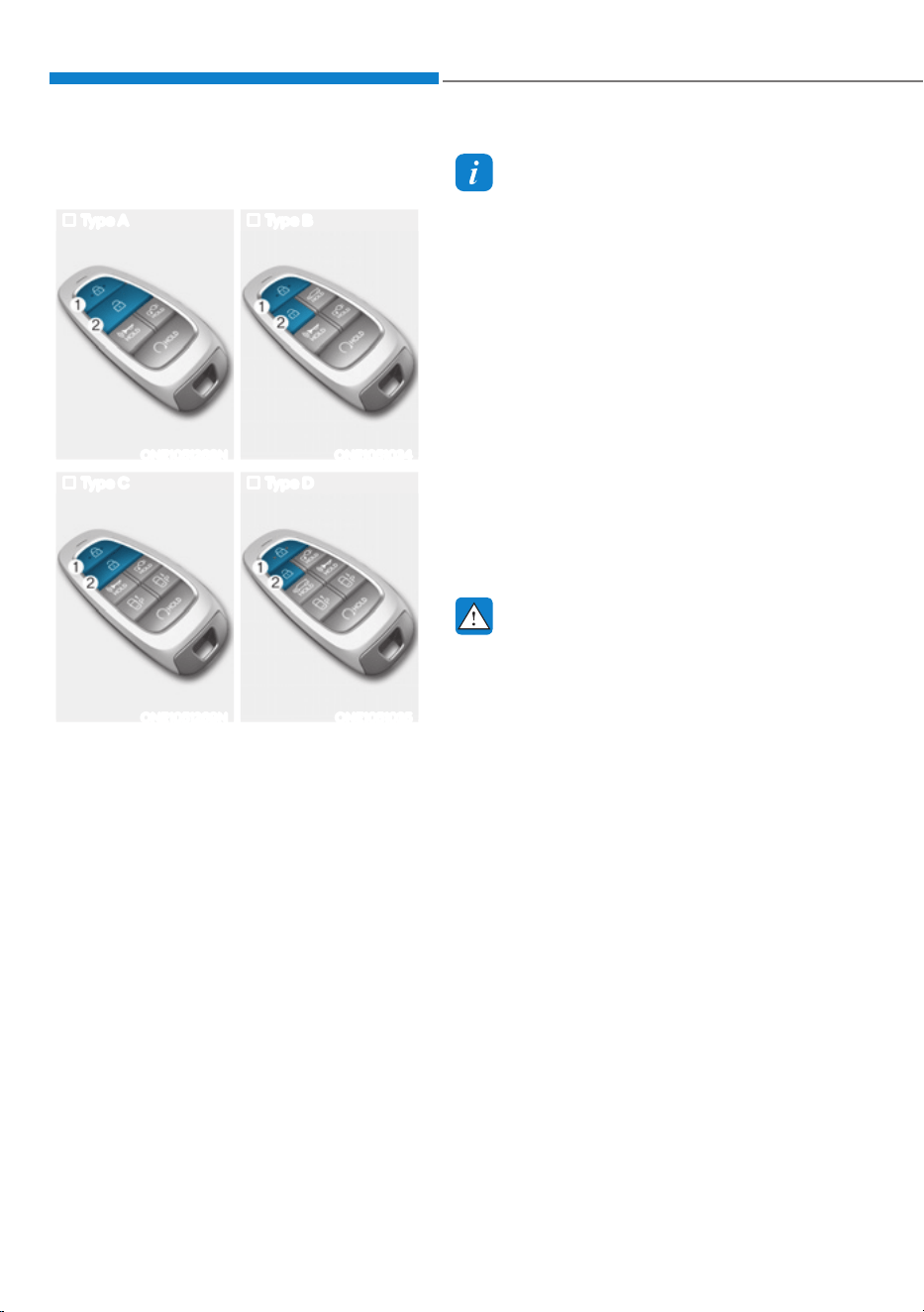
Convenience Features
5-66
Remote window opening/closing
function (if equipped)
Type A Type B
ONE1051268N ONE1051034
Type C Type D
ONE1051269N ONE1051035
You can still control the window
movement with the vehicle turned off by
pressing the Door Lock button (1) or the
Door Unlock button (2).
ś Press the door lock button for more
than 3 seconds. The doors will lock
and the windows will move up as long
as you press the door lock button.
ś Press the door unlock button for more
than 3 seconds. The doors will unlock
and the windows will move down as
long as you press the door unlock
button.
Information
ś The remote window opening/closing
function will be operated only with the
6DIHW\3RZHU:LQGRZVHTXLSSHG
ś The remote window opening/closing
function may abruptly stop when you
move away from your vehicle during
operation. Stay in close proximity from
your vehicle, while monitoring the
window movement.
ś One of the windows may stop operating
when the window is interrupted by
certain force. However, the other
ZLQGRZVZLOONHHSRSHUDWLQJ0DNH
sure that all windows are closed.
ś 3OHDVHEHDZDUHWKDWWKHGRRUVXQORFN
when the windows are opened using the
remote window open/closing function.
WARNING
Always double check to make
sure arms, hands, head and other
obstructions are safely out of the way
before using remote window closing
function.
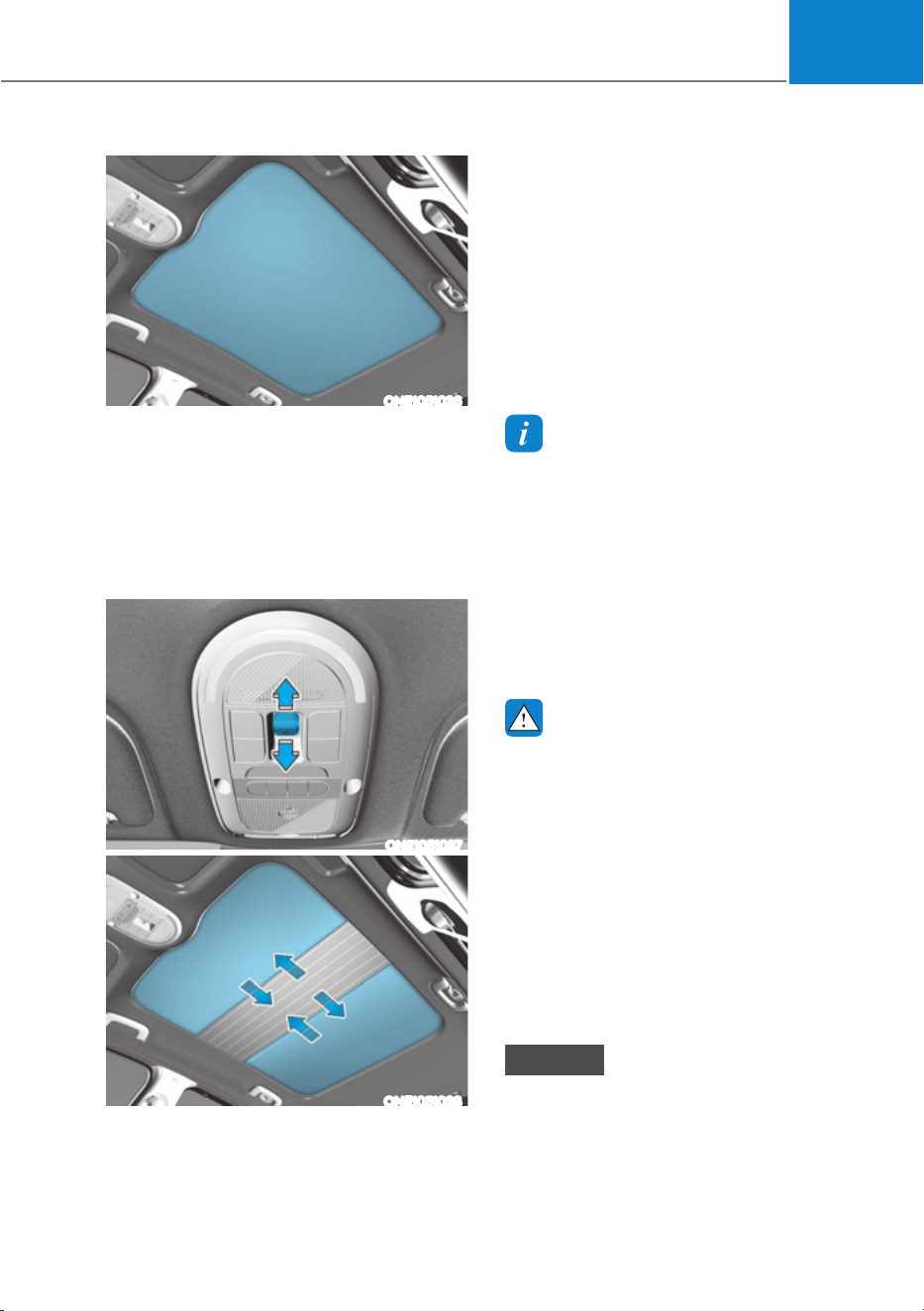
05
5-67
ONE1051036
If your vehicle is equipped with a vision
roof, you can slide open the power
sunshade and an all-glass roof appears.
Power sunshade
Use the power sunshade to block direct
sunlight coming through the vision roof
glass.
ONE1051037
ONE1051038
The power sunshade can only be
operated when Start/Stop button is in
the ON or START position.
ś Push the switch rearward, the power
sunshade automatically slides open.
ś Push the vision roof switch forward,
the power sunshade automatically
closes.
To stop the power sunshade at any point,
push the switch in any direction.
Information
ś The power sunshade can be operated
for approximately 3 minutes after the
Start/Stop button is in the ACC or OFF
position. However, if the front door
is open, the power sunshade cannot
be operated even within the 3 minute
period.
ś :ULQNOHVIRUPHGRQWKHSRZHU
sunshade are normal due to material
characteristic.
WARNING
ś Adjust the power sunshade when
your vehicle stops. This could result
in loss of control and an accident
that may cause injury, or property
damage.
ś Do not leave the vehicle running
and the key in your vehicle with
unsupervised children. Unattended
children could operate the power
sunshade, which could result in
injury.
ś Do not sit on the top of the vehicle. It
may cause injury or vehicle damage.
NOTICE
Do not pull or push the power sunshade
by hand as such action may damage
the power sunshade or cause it to
malfunction.
9,6,21522)ǣ,)(48,33('Ǥ
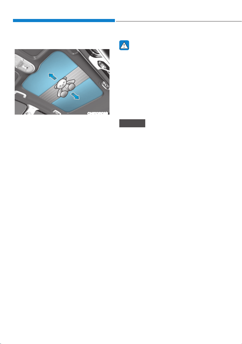
Convenience Features
5-68
Automatic reversal
ONE1051039
If the power sunshade senses any
obstacle while it is closing automatically,
it will reverse direction then stop at a
certain position.
The auto reverse function may not
work if an object thin or soft is caught
between the sliding power sunshade and
vision roof sash.
WARNING
ś Make sure heads, hands, arms or any
other body parts or objects are out of
the way before operating the power
sunshade . Body parts or objects may
get caught causing injuries or vehicle
damage.
ś Never deliberately use your body
parts to test the automatic reversal
function. The power sunshade may
reverse direction, but there is a risk
of injury.
NOTICE
Do not continue to push the switch after
the power sunshade is fully opened or
closed. Damage to the power sunshade
motor could occur.
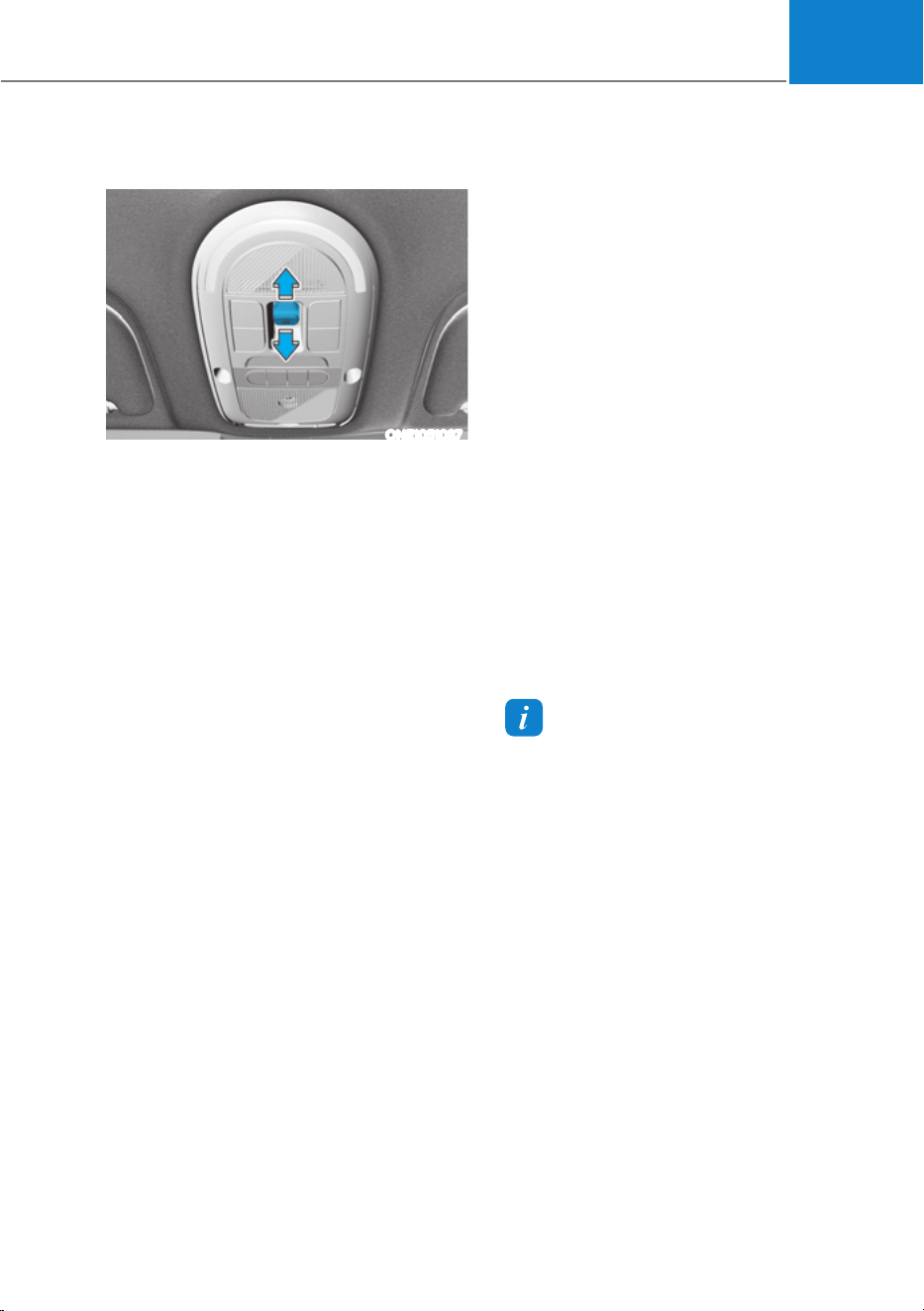
05
5-69
Resetting the Vision Roof
ONE1051037
In some circumstances resetting the
power sunshade operation may need to
be performed. Some instances where
resetting the power sunshade may be
required include:
ś When the 12-volt battery is either
disconnected or discharged
ś When the power sunshade fuse is
replaced
ś If the power sunshade one-touch
AUTO OPEN/CLOSE operation is not
functioning properly
Vision roof resetting procedure:
1. It is recommended to perform the
reset procedure with the vehicle in
the ready mode. Start the vehicle in P
(Park).
2. Make sure the power sunshade is in
the fully closed position. If the power
sunshade is open, push the switch
forward until the power sunshade and
is fully closed.
3. Release the switch when the power
sunshade is fully closed.
4. Push the switch forward until the
power sunshade moves slightly. Then
release the switch.
5. Once again push and hold the switch
forward until the power sunshade
slides open and close. Do not release
the switch until the operation is
completed.
If you release the switch during
operation, start the procedure again
from step 2.
Information
If the power sunshade is not reset when
the vehicle battery is disconnected or
discharged, or the power sunshade fuse
is blown, the power sunshade may not
operate normally.
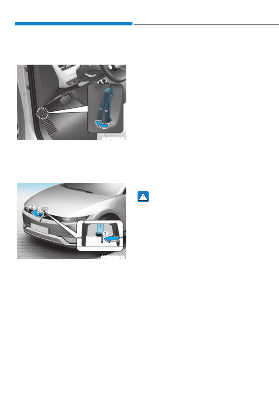
Convenience Features
5-70
EXTERIOR FEATURES
Hood
Opening the hood
ONE1051041
1. Park the vehicle and set the parking
brake.
2. Pull the release lever to unlatch the
hood. The hood should pop open
slightly.
ONE1051042
3. Go to the front of the vehicle, raise
the hood slightly, push to the left the
secondary latch (1) inside of the hood
center and lift the hood (2).
Closing the hood
1. Before closing the hood, check in and
around the motor compartment to
ensure the following:
- Any tools or other loose objects are
removed from the motor room area
or hood opening area
- All glove, rags, or other
combustible material is removed
from the motor compartment
- All filler caps are tightly and
correctly installed
2. Lower the hood halfway (lifted
approximately 30 cm (12 in.) from the
closed position) and push down to
securely lock in place. Then double
check to be sure the hood is secure.
If the hood can be raised slightly, it is
not securely locked. Open it again and
close it with more force.
WARNING
ś Before closing the hood, ensure
all obstructions are removed from
around the hood opening. The
hood will rise up or move down
automatically if the height is not
firmly adjusted. Be aware of the
damage caused by the unintended
hood movements.
ś Always double check to be sure that
the hood is firmly latched before
driving away. Check there is no
hood open warning light or message
displayed on the instrument cluster.
Driving with the hood opened may
cause a total loss of visibility, which
might result in an accident.
ś Do not move the vehicle with the
hood in the raised position, as vision
is obstructed, which might result in
an accident, and the hood could fall
or be damaged.
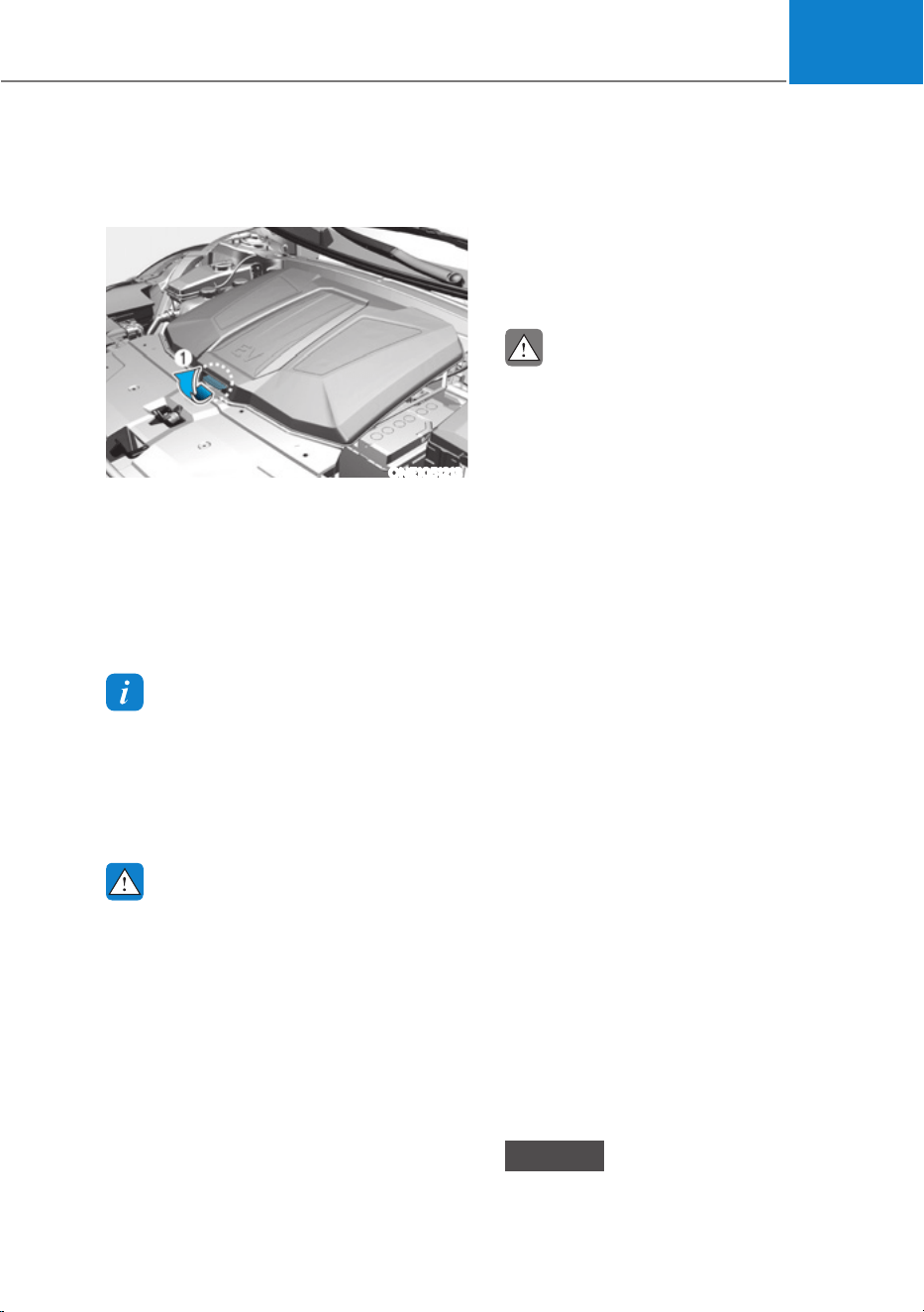
05
5-71
Front trunk
Opening the Front Trunk
ONE1051213
ś Open the hood
ś Lift up the front trunk cover while
depressing the front trunk lever (1).
Closing the Front Trunk
Push down the front trunk cover to the
right position.
Information
Available front trunk weight
ś :'OEVNJ
ś $:'OEVNJ
Available front trunk weight depends on
the specifications.
WARNING
ś NEVER make an attempt to get inside
the front trunk. It will cause a fatal
injury.
ś Before closing the hood, ensure
all obstructions are removed from
around the hood opening. The
hood will rise up or move down
automatically if the height is not
firmly adjusted. Be aware of the
damage caused by the unintended
hood movements.
ś Never store cigarette lighters,
propane cylinders, or other
flammable/explosive materials in
the vehicle. These items may catch
fire and/or explode if the vehicle
is exposed to hot temperatures for
extended periods.
CAUTION
ś Do not exceed the luggage volume
capacity of the front trunk. The
overweighted front trunk can be
severely damaged.
ś Do not store the fragile objects in the
front trunk.
ś ALWAYS keep the front trunk cover
closed securely while driving. Items
inside your vehicle are moving as fast
as the vehicle. If you have to stop or
turn quickly, or if there is a crash, the
items can be damaged.
ś Do not spray water in the front
trunk. Vehicle driving system may
get damaged since the front trunk
is located at the center of motor
compartment.
ś Be careful when you store any liquid
in the front trunk. If liquid leak
outside the front trunk, it will cause a
damage to the electric devices in the
motor compartment.
ś Do not press the front trunk cover
or place the objects on the front
trunk cover. It may be deformed or
damaged.
ś When closing the front trunk cover,
be careful not to touch objects
inside the trunk. Loaded objects or
the front trunk may be deformed or
damaged and the front trunk cover
may be opened during driving due to
poor closing, resulting in joints and
damage.
NOTICE
To avoid possible theft, do not leave
valuables in the storage compartments.
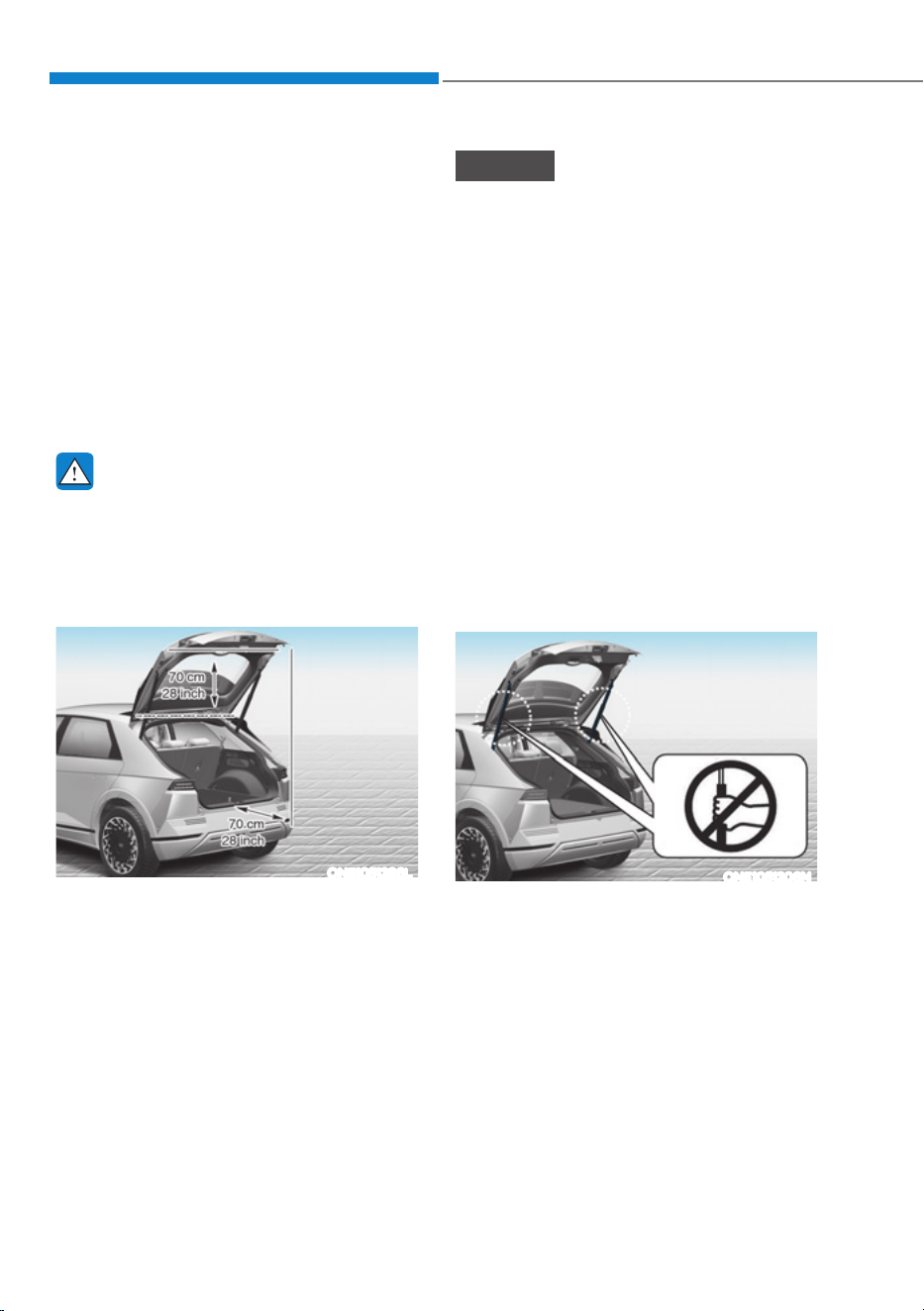
Convenience Features
5-72
Power Liftgate (If equipped)
Power liftgate operating conditions
The power liftgate operates when
the gear is in P (Park) with the vehicle
running. However, the power liftgate will
operate regardless of the gear position
when the vehicle is off. Also, the liftgate
can be opened only when vehicle speed
is below 1.8 mph (3 km/h).
For safety, before attempting to open or
close the liftgate, make sure the vehicle
is in P (Park).
WARNING
ś Never leave children or animals
unattended in your vehicle. Children
may operate the power liftgate.
Doing so can result in injury to
themselves or others and can
damage the vehicle.
ONE1051286L
ś Make sure that there are no people
or objects in the path of the power
liftgate or smart liftgate prior to
use. Serious injury, damage to the
vehicle or damage to surrounding
objects (for example, walls, ceilings,
vehicles, etc.) may result if contact
with the liftgate occurs.
NOTICE
ś Do not close or open the liftgate
manually. This may cause damage to
the power liftgate. If it is necessary
to close or open the liftgate manually
when the battery is discharged or
disconnected, do not apply excessive
force.
ś Do not operate the power liftgate
more than 10 times continuously
when the vehicle is not running. Use
the power liftgate with the vehicle
running when the power liftgate is
used repeatedly to prevent battery
discharge.
ś Do not leave the power liftgate open
for a long period of time. This may
drain the battery.
ś Do not apply excessive force when
the power liftgate is operating. Doing
so could result in vehicle damage.
ONE1051206N
ś Do not grab or hold on to the liftgate
support struts at any time. Damage
to the liftgate support struts could
result. Deformation of the liftgate
support struts may cause vehicle
damage and personal injury may
occur.
ś Do not modify or repair any part
of the power liftgate by yourself.
This must be done by an authorized
HYUNDAI dealer.

05
5-73
ś Do not operate the power liftgate
under the following conditions.
The power liftgate may not operate
properly.
- One side of the vehicle is lifted to
inspect the vehicle or change a tire
- Parking on an uneven road such as
a slope, etc.
ś Close the liftgate completely and
lock all doors and liftgate using the
central door lock button before using
an automatic car wash.
ś Do not spray high pressure water
directly on the power liftgate outside
open/close button. The liftgate may
open unintentionally.
Information
ś If the liftgate is not fully closed and
vehicle speed is at or above 1.8 mph (3
km/h), a warning will sound 10 times.
Immediately park the vehicle at a safe
place, close the liftgate, and check
that the liftgate open warning on the
instrument cluster is turned off.
ś In cold and wet climates, the outside
power liftgate open/close button may
not work properly due to freezing
conditions. If this occurs, remove the
ice before using the outside power
liftgate open/close button or use the
power liftgate open/close button on the
smart key or the instrument panel.
ś Operating the power liftgate more
than 5 times continuously could cause
damage to the operating motor. If
this occurs, the power liftgate will not
operate to prevent the motor from
overheating. If any of the power liftgate
buttons are pressed to try to open the
liftgate, the chime will sound 3 times,
but the liftgate will remain closed.
Allow the power liftgate system to cool
for about 1 minute before operating the
system again.
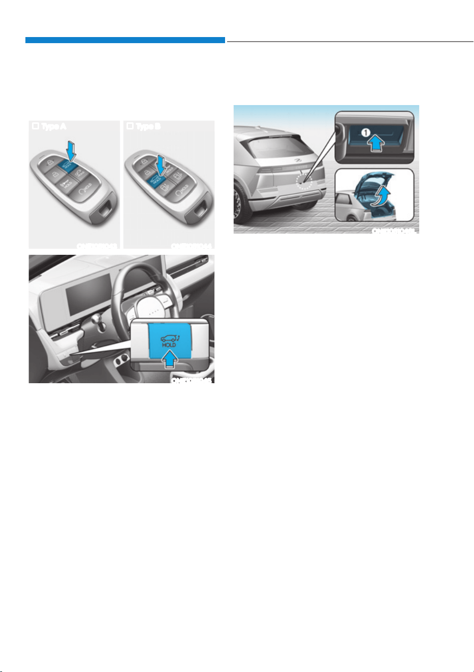
Convenience Features
5-74
Operating the power liftgate
3RZHUOLIWJDWHRSHQFORVHEXWWRQ6PDUW
key, Instrument panel)
Type A Type B
ONE1051043 ONE1051044
ONE1051045
When the liftgate is closed, press the
power liftgate open/close button for 1
second. The power liftgate opens with a
warning sound.
While the liftgate is opening, press the
button to stop liftgate operation.
When the power liftgate is opened, press
and hold the power tailgate open/close
button to close the liftgate. If you release
the button while the tailgate is closing,
power liftgate operation will stop with a
warning sound for 5 seconds.
Also, if the smart key is not within
operation range (approximately 394
in.(10 m)) from the vehicle, power liftgate
operation will stop with a warning sound
for 5 seconds.
3RZHUOLIWJDWHRSHQFORVHEXWWRQ2XWVLGH
the power liftgate)
ONE1051046L
When the liftgate is closed, press the
power liftgate open/close button (1) to
open the liftgate.
If the vehicle is locked, press the power
liftgate open/close button (1) with the
smart key in your possession.
If the liftgate is unlocked, the liftgate
will open or close with a warning sound
when the power liftgate open/close
button (1) is pressed without carrying the
smart key.
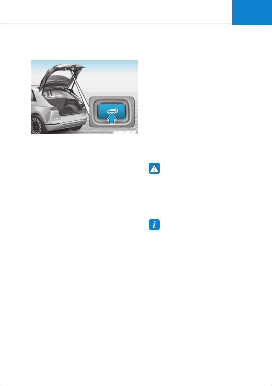
05
5-75
3RZHUOLIWJDWHRSHQFORVHEXWWRQ,QVLGH
the power liftgate)
ONE1051047
Press the power liftgate open/close
button. The liftgate opens or closes with
a warning sound.
Automatic reverse
During power liftgate operation if the
power liftgate senses any obstacle, the
liftgate will stop or will fully open. The
automatic reverse feature may not
operate properly, or it may operate
unexpectedly under the following
circumstances:
ś The automatic reverse feature may
not detect the resistance if the
detected resistance is below a certain
level, or if the liftgate is almost fully
closed near the latched position.
ś The automatic reverse feature may
operate if a strong impact is applied
with no obstructions placed.
WARNING
Never intentionally place any object
or part of your body in the path of
the power liftgate to make sure the
automatic reverse feature operates.
Serious injury, or damage to the vehicle
or object may occur.
Information
The power liftgate may stop operating if
the automatic reverse feature operates
more than two times while attempting to
open or close the liftgate. If this occurs,
carefully open or close the liftgate
manually, and then after 30 seconds try to
operate the power liftgate automatically
again.

Convenience Features
5-76
Setting the power liftgate
To use each feature, you must select the
opening speed or opening height from
the settings menu. Deselect the settings
when you do not want to use the feature.
3RZHUOLIWJDWHRSHQLQJVSHHG
To adjust the power liftgate speed,
VHOHFWœ6HWXSƟ9HKLFOH6HWWLQJVƟ'RRU
OLIWJDWHƟ3RZHUOLIWJDWH2SHQLQJ6SHHG
Ɵ)DVW6ORZŔLQWKHLQIRWDLQPHQWV\VWHP
(Default setting is ‘Fast’.)
3RZHUOLIWJDWHRSHQLQJKHLJKW
To adjust the power liftgate opening
KHLJKWVHOHFWœ6HWXSƟ9HKLFOH6HWWLQJV
Ɵ'RRUOLIWJDWHƟ3RZHUOLIWJDWH2SHQLQJ
+HLJKWƟ)XOO2SHQ/HYHO/HYHO/HYHO
1/User Height Setting’ in the infotainment
system.
The infotainment system may change
after updates. See additional information
in supplied Infotainment Manual.
User height setting
1. Position the liftgate manually to the
height you prefer.
2. Press the power liftgate open/close
button located inside the liftgate for
more than 3 seconds. If ‘User Height
Setting’ is selected for the power
liftgate opening height, the power
liftgate will automatically open to the
height manually set by you.
Information
ś If the power liftgate opening height
has not been manually set, the power
liftgate will fully open when ‘User
Height Setting’ from the infotainment
system is selected.
ś If one of the height setting (Full Open/
Level 3/Level 2/Level 1) is selected from
the settings menu in the infotainment
system, and then ‘User Height Setting’
is selected, the liftgate will open to the
height manually set by you.
ś The power liftgate opening speed
and opening height settings change
DFFRUGLQJWRWKHOLQNHG8VHU3URILOH
,IWKH8VHU3URILOHLVFKDQJHGSRZHU
liftgate opening speed and opening
height settings will change accordingly.
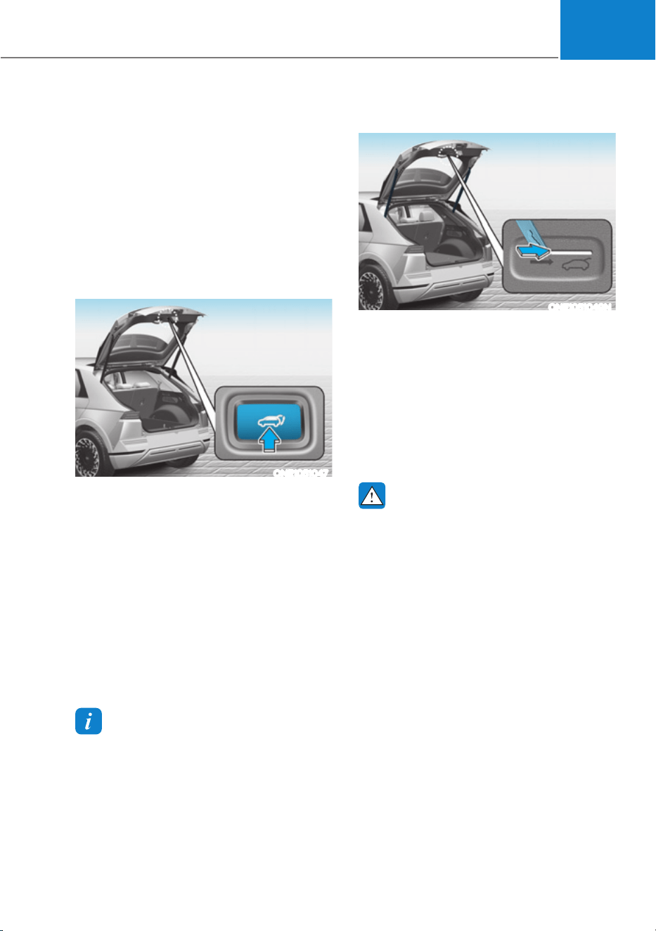
05
5-77
Resetting the power liftgate
In some circumstances resetting the
power liftgate operation may need to
be performed. Some instances where
resetting the power liftgate may be
required include:
ś When the 12-volt battery is recharged
ś When the 12-volt battery is reinstalled
after removal or replacement
ś When the related fuse is reinstalled
after removal or replacement
ONE1051047
1. With the vehicle off or running, put
the gear in P (Park).
2. Press the power liftgate open/close
inner button simultaneously until a
chime sounds.
3. Slowly close the liftgate manually.
4. Press the power liftgate open/close
outer button. The power liftgate will
open with a chime sound. Wait until
the liftgate fully opens to complete
resetting. If the liftgate stops before
it is fully open, resetting cannot be
completed.
Information
If the power liftgate does not operate
properly after the above procedure, have
the system inspected by an authorized
HYUNDAI dealer.
Emergency liftgate safety release
ONE1051049N
To unlock and open the liftgate manually
from inside the luggage compartment,
perform the following procedure:
1. Insert a long, flat object, such as a key
into the opening at the bottom of the
liftgate.
2. Slide the latch in the direction of the
arrow to unlock the liftgate.
3. Push the liftgate to open.
WARNING
ś For emergencies, be fully aware
of the location of the emergency
liftgate safety release latch in the
vehicle and how to open the liftgate
if you are accidentally locked in the
luggage compartment.
ś No one, including animals, should
be allowed to occupy the luggage
compartment of the vehicle at any
time. The luggage compartment is a
very dangerous location in the event
of an accident.
ś Use the release latch for
emergencies only. Use extreme
caution, especially while the vehicle
is in motion.
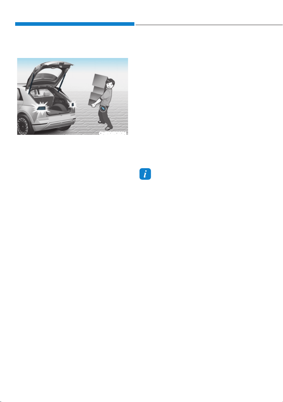
Convenience Features
5-78
Smart Liftgate (if equipped)
ONE1051050N
On a vehicle equipped with a smart key,
the liftgate can be opened with hands-
free activation using the smart liftgate
system.
Using smart liftgate
The hands-free smart liftgate system
can be opened automatically when the
following conditions are met:
ś The smart liftgate option is enabled in
the Settings menu in the infotainment
system screen.
ś The smart liftgate is activated and
ready 15 seconds after all the doors
are closed and locked.
ś The smart liftgate will open when
the smart key is detected in the area
behind the vehicle for 3 seconds.
ś When disconnecting the charging
connector, the smart liftgate is
activated.
Information
The smart liftgate will NOT operate when:
ś A door is not locked or closed.
ś The smart key is detected within
15 seconds from when the doors were
closed and locked.
ś The smart key is detected within
15 seconds after the doors are closed
and locked, and within 1.5 m (60 in.)
from the front door handles. (for
YHKLFOHVHTXLSSHGZLWK:HOFRPH
0LUURU
ś The smart key is in the vehicle.
ś The vehicle is on charge.
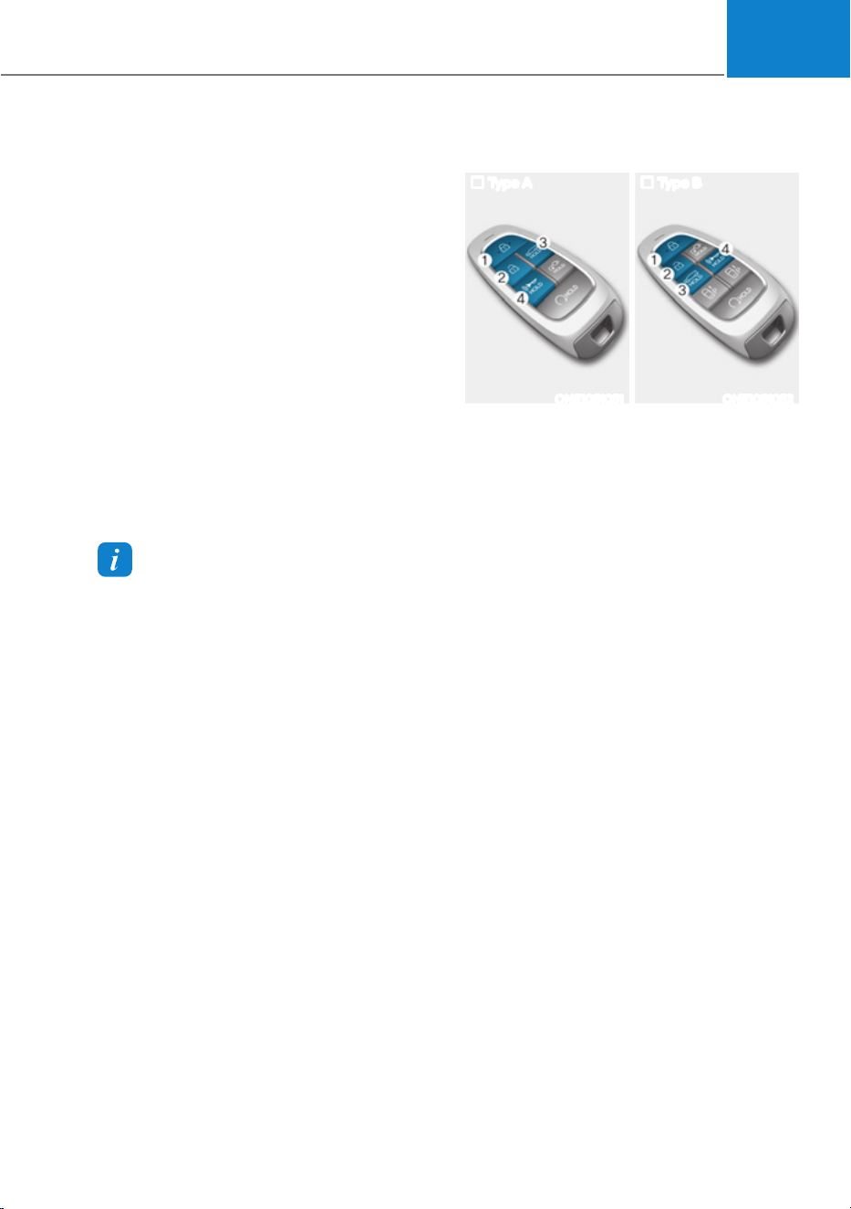
05
5-79
1. Settings
To use smart liftgate, it must be
enabled from the Settings menu in the
infotainment system screen. Select:
- 6HWXSƟ9HKLFOH6HWWLQJVƟ'RRU
/LIWJDWHƟ6PDUW/LIWJDWH
For detailed information, refer to the
separately supplied infotainment
system manual.
2. Detect and Alert
The smart liftgate detecting area
extends approximately 50-100 cm
(20-40 in.) behind the vehicle. If you
are positioned in the detecting area
and are carrying the smart key, the
hazard warning lights will blink and
the chime will sound to alert you that
the smart liftgate will open.
Information
Do not approach the detecting area if you
do not want the liftgate to open. If you
have unintentionally entered the detecting
area and the hazard warning lights and
chime starts to operate, move away from
the area behind the vehicle with the smart
key. The liftgate will remain closed.
3. Automatic opening
After the hazard warning lights blink
and the chime sounds 6 times, the
smart liftgate will open.
Deactivating smart liftgate
Type A Type B
ONE1051051 ONE1051052
1. Door lock
2. Door unlock
3. Liftgate open/close
4. Panic
If you press any button on the smart key
during the Detect and Alert stage, the
smart liftgate will be deactivated.
Make sure to be aware of how to
deactivate the smart liftgate for
emergency situations.
ś If you press the door unlock button
(2), the smart liftgate will be
deactivated temporarily. But, if you do
not open any door for 30 seconds, the
smart liftgate will be activated again.
ś If you press the liftgate open button
(3) for more than 1 second, the liftgate
opens.
ś The smart liftgate will still be activated
if you press the door lock button (1) or
liftgate open/close button (3) on the
smart key as long as the smart liftgate
is not already in the Detect and Alert
stage.
ś In case you have deactivated the
smart liftgate by pressing the smart
key button and opened a door, the
smart liftgate can be activated again
by closing and locking all doors.
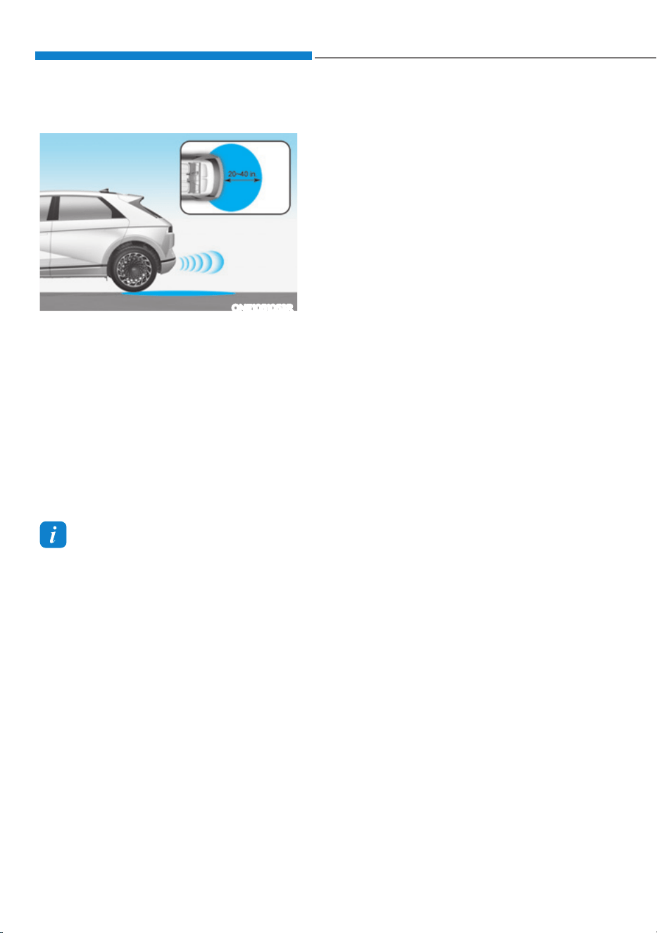
Convenience Features
5-80
Detecting area
ONE1051053R
ś The smart liftgate detecting area
extends approximately 50-100 cm
(20-40 in.) behind the vehicle. If you
are positioned in the detecting area
and are carrying the smart key, the
hazard warning lights will blink and
the chime will sound for about 3
seconds to alert you that the liftgate
will open.
ś The alert stops once the smart key is
moved outside of the detecting area
within the 3 second period.
Information
ś Smart liftgate may not operate
properly if any of the following occur:
- The smart key is close to a radio
transmitter such as a radio station or
an airport which can interfere with
normal operation of the transmitter.
- The smart key is near a mobile two
way radio system or a mobile phone.
- Another vehicle’s smart key is being
operated close to your vehicle.
ś Smart liftgate detecting area may
change when:
- The vehicle is parked on an incline
or slope.
- One side of the vehicle is raised or
lowered relative to the opposite side.

05
5-81
ELECTRIC CHARGING DOOR
ONE1Q011040
The driver can open and close the
charging door with the following
methods:
ś When the shift gear is in P (Park), push
the charging door to open/close
ś Push the Close button located inner
part of the charging door
ś Press the charging door button in the
smart key
ś Use the Voice Recognition
NOTICE
ś If the charging door does not open
because ice has formed around it,
tap lightly or push on the door to
break the ice and release the door.
If necessary, use hand temperature
to melt down the ice or move the
vehicle to a warm place and allow
the ice to melt. Do not pry on the
charging door or use unauthorized
tools to open the charging door.
ś After closing the charging door, push
the door again to ensure that the
charging door is completely closed.
ś Make sure that the charging door is
closed before driving the vehicle.
If the charging door is opened,
mechanical parts of the charging
door can be damaged.
ś After closed the charging door, be
sure to check the warning light is off.
ś After charging the vehicle, close
the charging inlet by the charging
inlet cover properly. If the charging
inlet cover is closed improperly, the
charging inlet and the charging door
can be damaged.
ś Do not pry on the charging door
while the charging door is opening.
The charging door may stop moving.
Also, the electrical mechanism of the
charging door and its related parts
can be severely damaged.
ś While washing the vehicle, do not
spray a high pressure water to the
charging door directly. The high
pressure can damage the charging
door.
CAUTION
ś The charging door opens upwards.
Check the surrounding while the
charging door is open or close. Be
aware of your head or limbs from
being hit or stuck to the charging
door.
ś Do not hold the hinge to prevent
damaging the charging door and
causing other accidents.
Information
ś The charging door automatically closes
when:
- The charging connector is
disconnected
- The door is opened and the charging
connector is not connected for a
certain period of time
- 7KHJHDULVQRWLQ33DUN
ś After replacing battery (12 volt), open
and close the charging door once to
check that the charging door automatic
opening mechanism is functioning
properly.
For more details, refer to “Charging
Electric Vehicle” section in chapter 1.
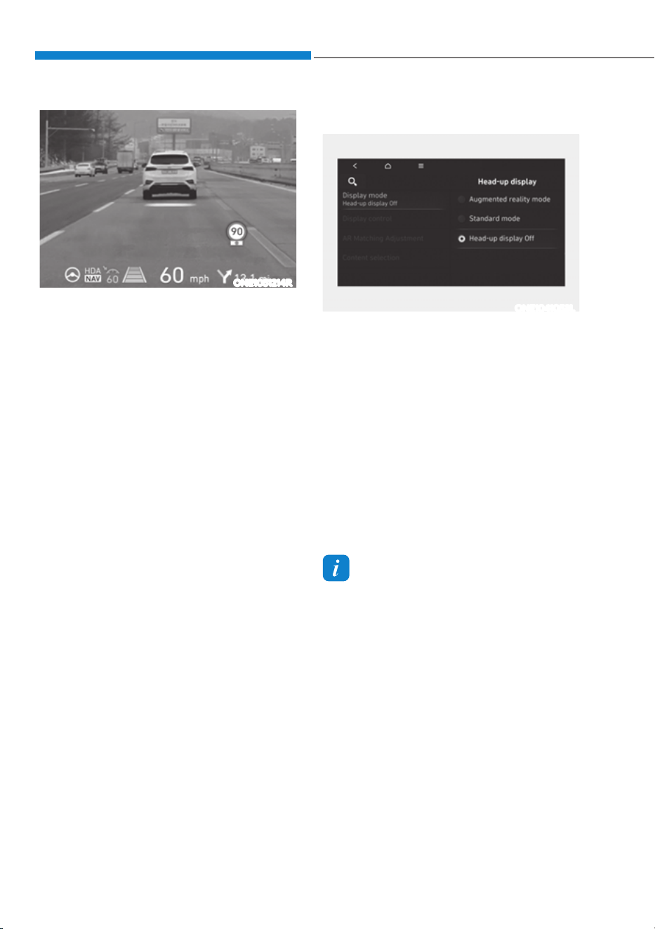
Convenience Features
5-82
ONE1051214R
The Head-Up Display is an optional
feature that allows the driver to view
information projected onto a transparent
screen while still keeping your eyes
safely on the road ahead while driving.
Head-up display Settings
ONE1041053L
ś Head-up display can be enabled
from the Settings menu in the
infotainment system screen. Select
either Augmented Reality (AR) mode
or Standard mode from:
- 6HWXSƟ9HKLFOHƟ+HDG8S'LVSOD\
Ɵ'LVSOD\PRGHƟ$XJPHQWHGUHDOLW\
mode / Standard mode
ś After turning on the head-up display,
you can change the settings of
‘Display control’, ‘AR Matching
Adjustment’ (When AR mode is
selected) and ‘Content selection’ of
the Head-up display.
Information
Standard mode is the basic setting for
Head-up display.
For detailed information, refer to the
separately supplied infotainment system
manual.
$8*0(17('5($/,7<+8'ǣ,)(48,33('Ǥ
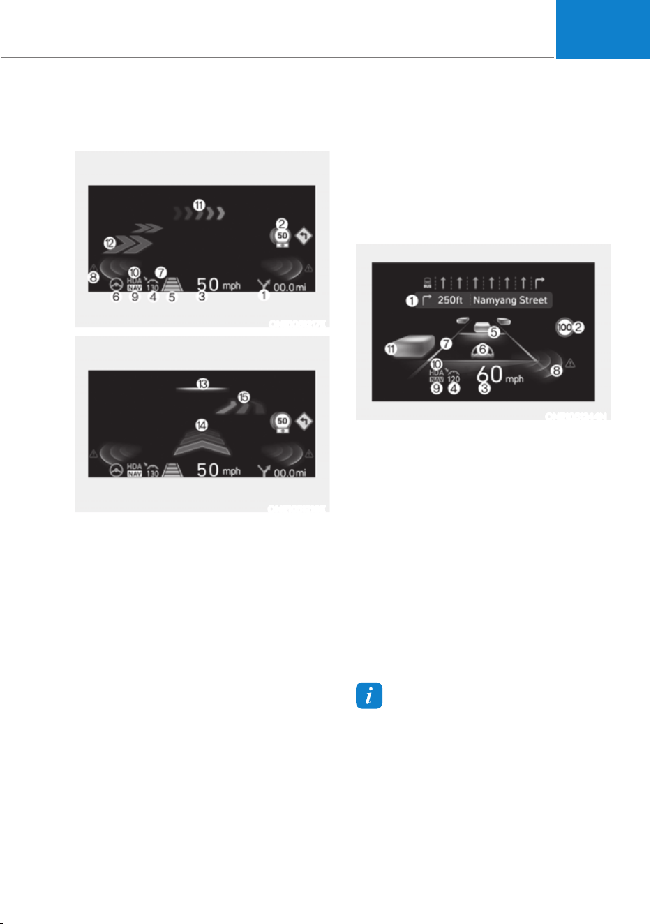
05
5-83
Head-up display Information
AR mode display information
ONE1051217E
ONE1051218E
1. Turn by Turn (TBT) navigation
information
2. Traffic information
3. Speedometer information
4. SCC set speed information
5. SCC vehicle distance information
6. Lane Following Assist information
7. Lane Safety information
8. Blind-Spot Safety information
9.
Highway Auto Speed Change
information
10.
Highway Driving Assist information
11.
Turn by turn (TBT) navigation
information (AR)
12.
Lane Safety Information (AR)
13.
Front Vehicle indicator (AR) (if
Highway Lane Change Assist function
equipped)
14.
Leading Vehicle Departure Alert (AR)
15.
Highway Lane Change Assist
information (AR)
Standard mode display information
ONE1051244N
1. Turn by Turn (TBT) navigation
information
2. Traffic information
3. Speedometer information
4. SCC set speed information
5. SCC vehicle distance information
6. Lane Following Assist information
7. Lane Safety information
8. Blind-Spot Safety information
9.
Highway Auto Speed Change
information
10.
Highway Driving Assist information
11.
Surrounding vehicle information
Information
Standard Head-up display information
may not be consistent based on the
different system settings menu.

Convenience Features
5-84
Precautions while Using the
Head-up display
ś It may sometimes be difficult to read
information on the Head-Up Display in
the following situations.
- The driver is improperly positioned
in the driver’s seat
- The driver wears polarizing-filter
sunglasses
- An object is located above the
head-up display cover
- The vehicle is driven on a wet road
- Any improper lighting accessory is
installed inside the vehicle, or there
is incoming light from outside of the
vehicle
- The driver wears glasses
- The driver wears contact lenses
When it is difficult to read the Head-
up display information, adjust the
image position, brightness level or
AR matching information from the
Settings menu in the infotainment
system screen.
ś The AR mode display information may
be difficult to recognize when the
vehicle is driven under severe weather
condition, such as heavy rain, heavy
snow, low visibility, etc.
ś Since the information displayed on
the head-up display partially overlaps
with the road ahead, you may feel
fatigue and discomfort while driving.
If you feel tired or uncomfortable,
adjust the image, and if the symptoms
persist, turn off the head-up display
before driving.
ś When the direct flash light or
sunlight hits the front windshield, a
warning message will appear. If the
temperature of the front windshield
keep rises, Head-up display will be
deactivated temporarily to protect
Head-up display from the high
temperature. When the temperature
drops, Head-up display will be
reactivated.
ś For your safety, make sure to stop the
vehicle before adjusting the settings.
ś Do not tint the front windshield glass
or add other types of metallic coating.
Otherwise, the Head-Up Display
image may be invisible.
ś Do not place any accessories on the
crash pad or attach any objects on the
windshield glass.
ś When replacing the front windshield
glass, replace it with a windshield
glass designed for Head-Up Display
operation. Otherwise, duplicated
images may be displayed on the
windshield glass.
WARNING
ś The warning information of Blind-
Spot Safety on the Head-Up Display
are supplemental. Do not solely
depend on them to change lanes.
Always take a look around before
changing lanes.
The driving route guidance display
in the augmented reality mode is an
auxiliary function. Be sure to check
the navigation screen together.
ś ALWAYS pay attention on the road
while driving when the Head-Up
Display is on.
Information
+HDG8S'LVSOD\LQFOXGHV*3//*3/
03/DQGRWKHURSHQVRXUFHOLFHQVH
softwares. All license notices including
related source code are provided at http://
www.mobis.co.kr/opensource/list.do.
If the driver requests on-board
VRIWZDUHRSHQVRXUFHFRGHYLD02%,6B
[email protected] within 3 years
DIWHUEX\LQJWKLVSURGXFWD&'520RU
other storage device will be sent with the
minimum cost covering storage device cost
and delivery cost.
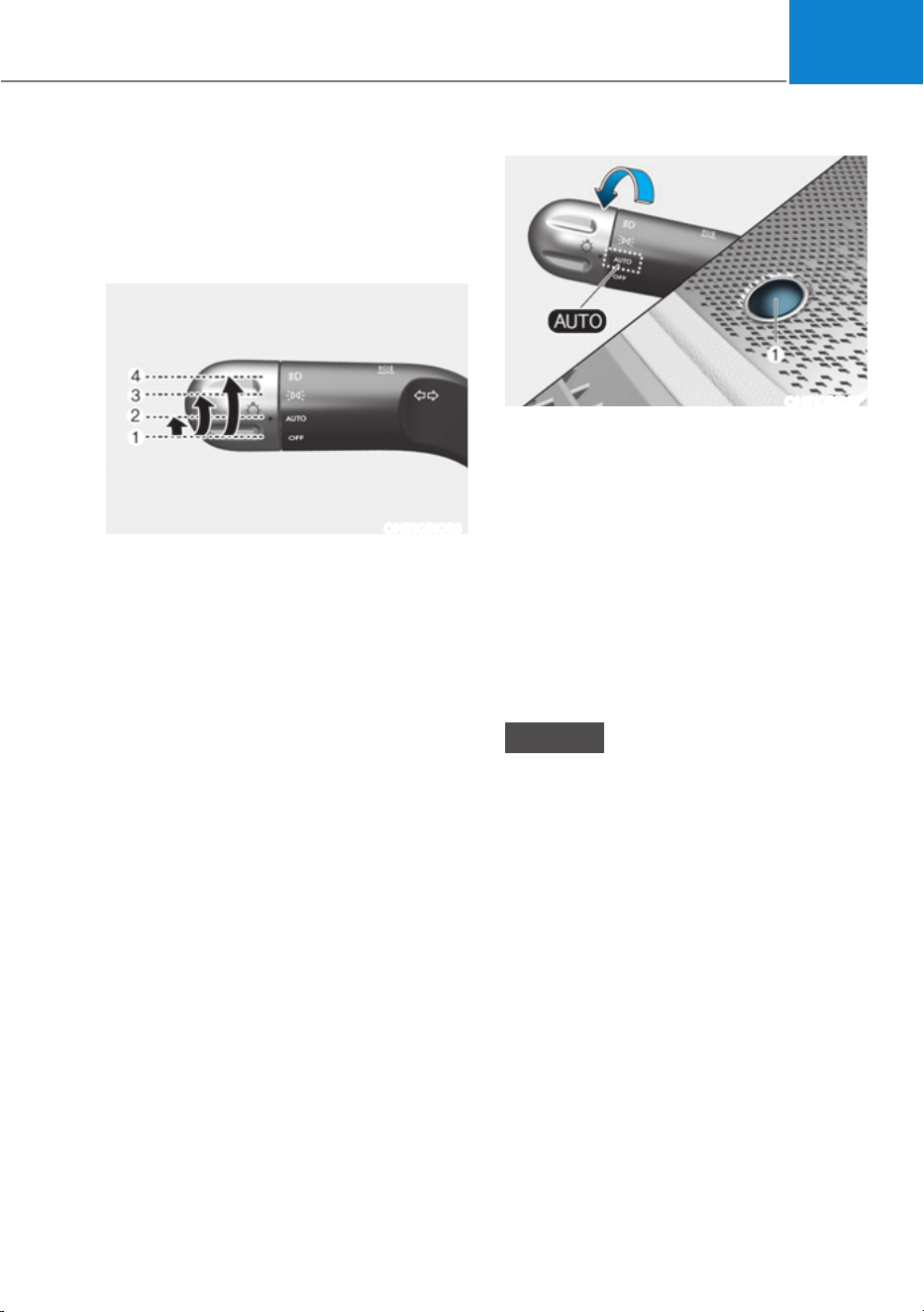
05
5-85
Exterior Lights
Lighting control
To operate the lights, turn the knob at
the end of the control lever to one of the
following positions:
ONE1051056
1. OFF position
2. AUTO headlamp position
3. Parking lamp position
4. Headlamp position
Daytime Running Light (DRL)
The Daytime Running Lights (DRL) can
make it easier for others to see the front
of your vehicle during the day, especially
after dawn and before sunset.
The DRL system will turn the dedicated
lamp OFF when :
ś The headlamps are ON.
ś The parking brake is applied.
ś The vehicle is turned off.
ONE1051057
AUTO headlamp position
The parking lamp and headlamp will
be turned ON or OFF automatically
depending on the amount of daylight as
measured by the ambient light sensor (1)
at the upper end of the windshield glass.
Even with the AUTO headlamp feature
in operation, it is recommended to
manually turn ON the headlamps when
driving at night or in a fog, driving in the
rain, or when you enter dark areas, such
as tunnels and parking facilities.
NOTICE
ś Do not cover or spill anything on the
sensor (1) located at the upper end of
the windshield glass.
ś Do not clean the sensor using
a window cleaner, the cleanser
may leave a light film which could
interfere with sensor operation.
ś If your vehicle has window tint or
other types of metallic coating on
the front windshield, the AUTO
headlamp system may not work
properly.
LIGHTING
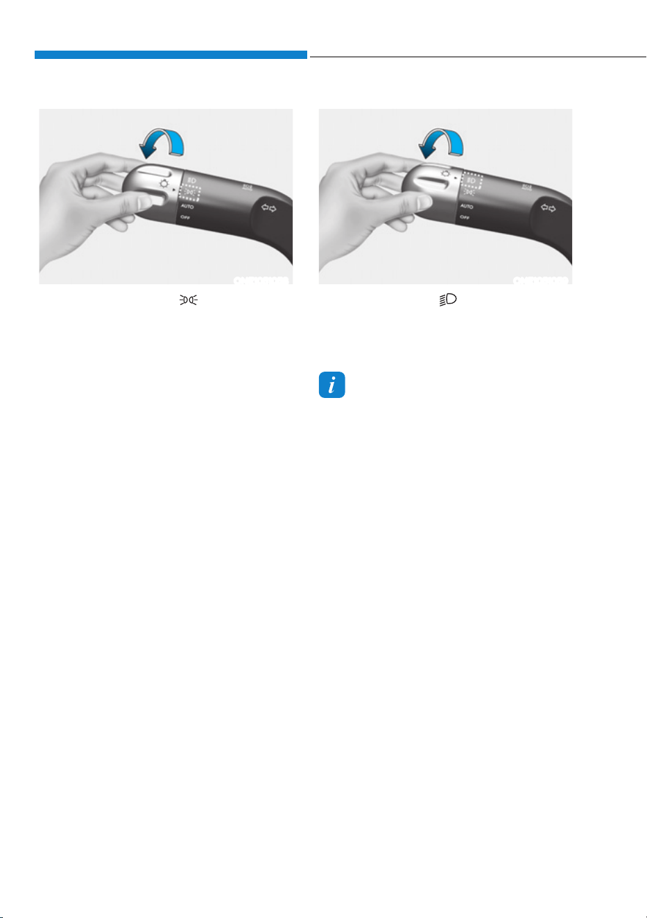
Convenience Features
5-86
ONE1051058
3DUNLQJODPSSRVLWLRQ( )
The parking lamp, license plate lamp and
instrument panel lamp are turned ON.
ONE1051059
Headlamp position ( )
The headlamp, parking lamp, license
plate lamp and instrument panel lamp
are turned ON.
Information
The Start/Stop button must be in the ON
position to turn on the headlamp.
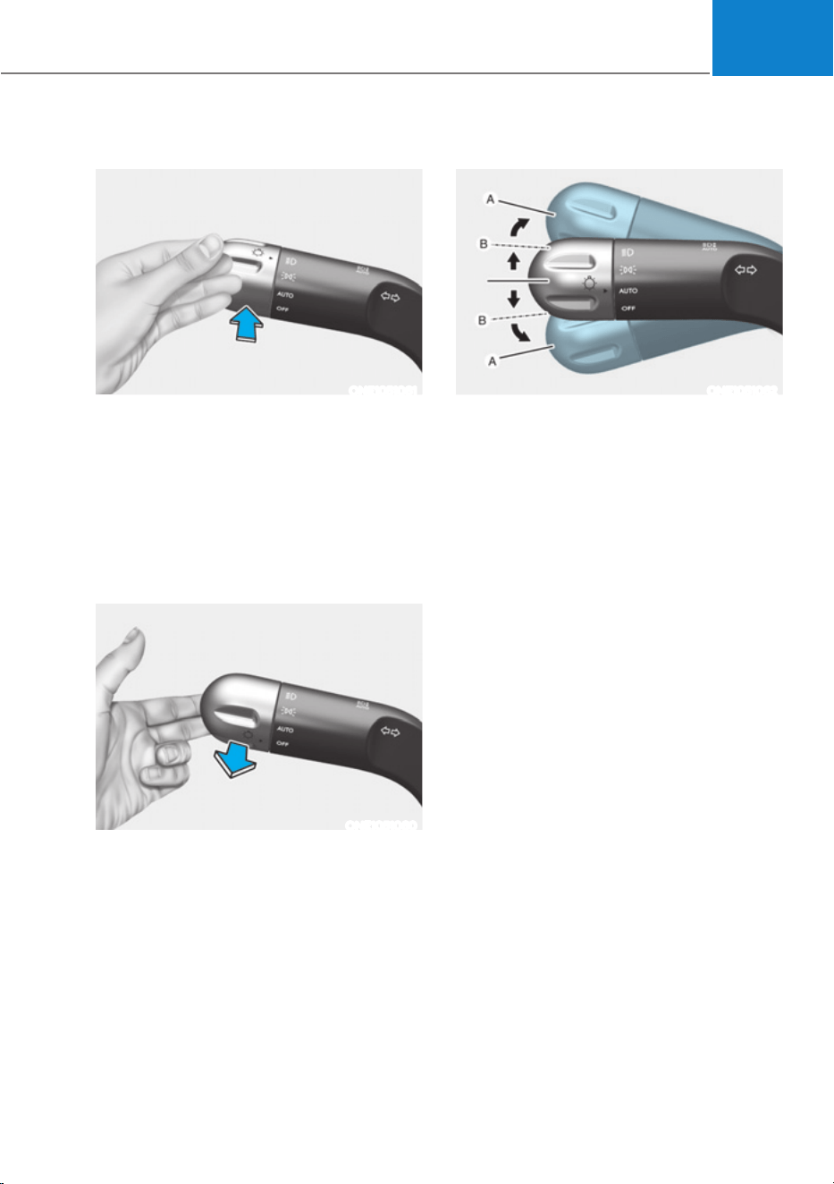
05
5-87
High beam operation
ONE1051061
To turn on the high beam headlamp,
push the lever away from you. The lever
will return to its original position.
The high beam indicator will light when
the headlamp high beams are switched
on.
To turn off the high beam headlamp, pull
the lever towards you. The low beams
will turn on.
ONE1051060
To flash the high beam headlamp, pull
the lever towards you, then release the
lever. The high beams will remain ON as
long as you hold the lever towards you.
Turn signals and lane change signals
ONE1051062
To signal a turn, push down on the lever
for a left turn or up for a right turn in
position (A).
If an indicator stays on and does not flash
or if it flashes abnormally, one of the turn
signal bulbs may be burned out and will
require replacement.
One touch turn signal
To use One Touch Turn Signal push the
turn signal lever up or down to position
(B) and then release it.
The lane change signals will blink 3, 5 or
7 times.
You can enable the One Touch Turn
Signal function or choose the number
RIEOLQNLQJE\VHOHFWLQJœ6HWXSƟ9HKLFOH
6HWWLQJVƟ/LJKWVƟ2QH7RXFK7XUQ6LJQDO
RU2QHWRXFKLQGLFDWRUƟIODVKHV
flashes/7 flashes/Off’ in the infotainment
system screen.
For detailed information, refer to the
separately supplied infotainment
system manual.

Convenience Features
5-88
Battery saver function
The purpose of this feature is to prevent
the battery from being discharged.
The system automatically turns off the
Parking lamp when the driver turns the
vehicle off and opens the driver-side
door.
With this feature, the Parking lamps will
turn off automatically if the driver parks
on the side of road at night.
However, the Parking lamps stay ON
even when the driver-side door is
opened if the light headlamp switch is
turned to the Parking lamp or AUTO (if
equipped) position after the vehicle is
turned off.
If necessary, to keep the lamps on
turn the Parking lamps OFF and ON
again using the headlamp switch on
the steering column after the vehicle is
turned off.
Headlamp delay function
If the Start/Stop button is in the ACC
position or the OFF position with the
headlamps ON, the headlamps (and/
or Parking lamps) remain on for about
5 minutes. However, if the driver’s door
is opened and closed, the headlamps
are turned off after 15 seconds. Also,
with the vehicle off if the driver’s door is
opened and closed, the headlamps (and/
or Parking lamps) are turned off after 15
seconds.
The headlamps (and/or Parking lamps)
can be turned off by pressing the lock
button on the smart key twice or turning
the headlamp switch to the OFF or AUTO
position.
You can enable the headlamp delay
IXQFWLRQE\VHOHFWLQJœ6HWXSƟ9HKLFOH
6HWWLQJVƟ/LJKWVƟ+HDGOLJKW'HOD\RU
Headlight time-out)’ in the infotainment
system screen.
For detailed information, refer to the
separately supplied infotainment
system manual.
NOTICE
If the driver exits the vehicle through
another door besides the driver
door, the battery saver function
does not operate and the headlamp
delay function does not turn OFF
automatically.
This may cause the battery to
discharge. To avoid battery discharge,
turn OFF the headlamps manually from
the headlamp switch before exiting the
vehicle.
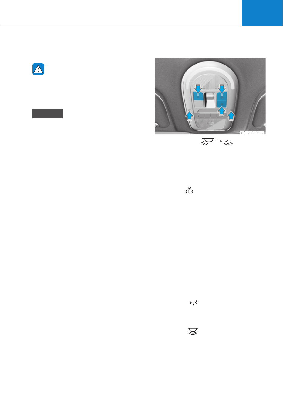
05
5-89
Interior Lights
WARNING
Do not use the interior lights when
driving in the dark. The interior lights
may obscure your view and cause an
accident.
NOTICE
Do not use the interior lights for
extended periods when the vehicle is
turned off or the battery will discharge.
Interior lamp AUTO cut
The interior lamps will automatically go
off approximately 20 minutes after the
vehicle is turned off and the doors are
closed. If a door is opened, the lamp
will go off 25 minutes after the vehicle
is turned off. If the doors are locked by
the smart key and the vehicle enters the
armed stage of the theft alarm system,
the lamps will go off five seconds later.
Front lamps
ONE1051065
Front map lamp ( ):
Touch either icons to turn the map lamp
on or off. This light produces a spot
beam for convenient use as a map lamp
at night or as a personal lamp for the
driver and the front passenger.
Door lamp ( ):
The front or rear room lamps come on
when the front or rear doors are opened.
When doors are unlocked by the smart
key, the front and rear lamps come on
for approximately 30 seconds as long as
any door is not opened. The front and
rear room lamps go out gradually after
approximately 30 seconds when the
door is closed. However, if the Start/Stop
button is in the ON position or all doors
are locked, the front and rear lamps will
turn off. If a door is opened with the
Start/Stop button in the ACC position
or the OFF position, the front and rear
lamps will stay on for about 5 minutes.
Room lamp ( )
Press the button to turn ON the room
lamp for the front/rear seats.
0RRGODPS( ) (if equipped)
Press the button to turn On the mood
lamp. Press again to turn the lamp off.
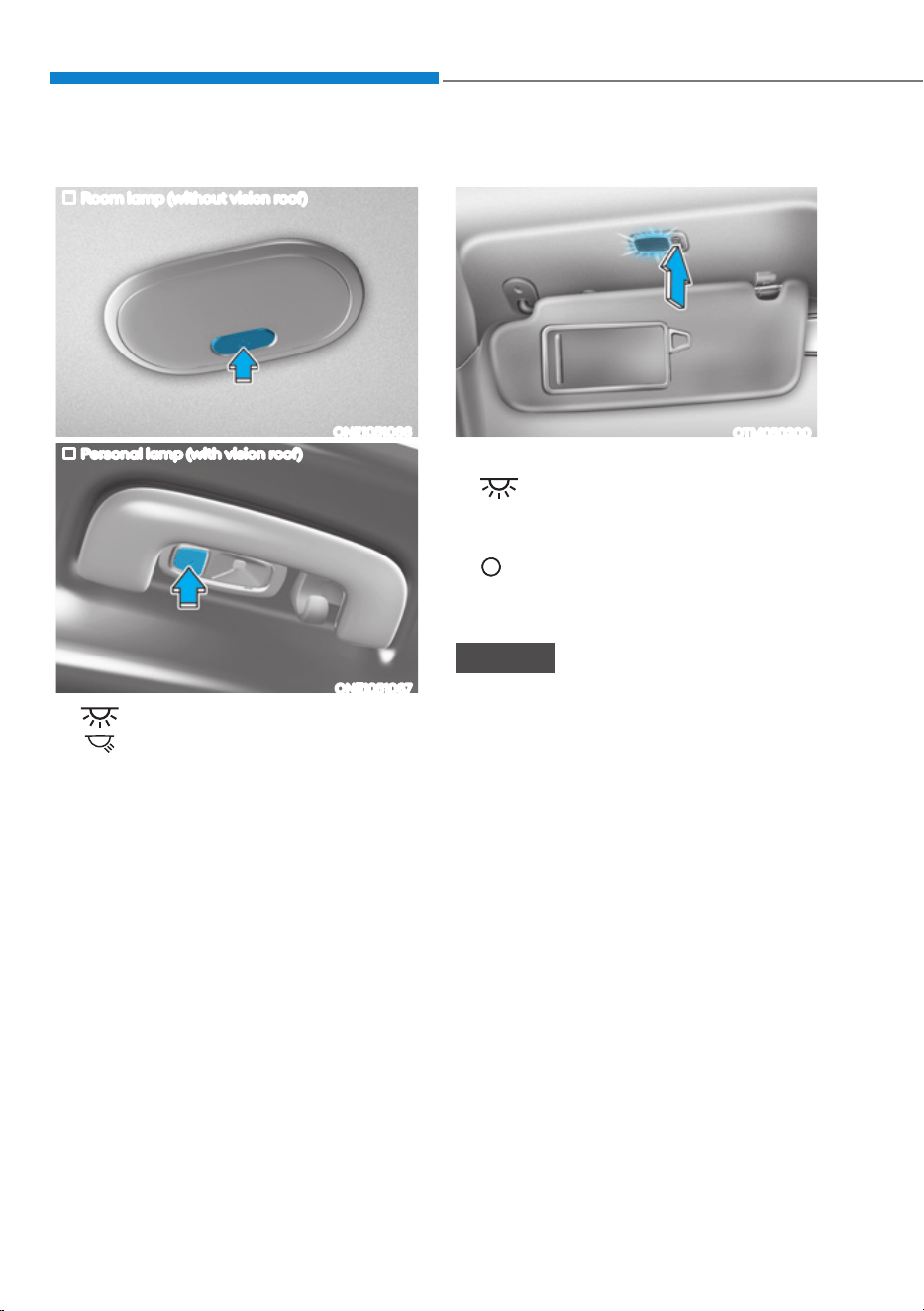
Convenience Features
5-90
Rear lamps
Room lamp (without vision roof)
ONE1051066
Personal lamp (with vision roof)
ONE1051067
ś
(Room lamp):
(Personal lamp):
Press the button to turn the lamp on
or off.
Vanity mirror lamp
OTM050200
Push the switch to turn the light on or off.
ś
:
The lamp will turn on if this button is
pressed.
ś
:
The lamp will turn off if this button is
pressed.
NOTICE
Always have the switch in the off
position when the vanity mirror lamp
is not in use. If the sunvisor is closed
without the lamp off, it may discharge
the battery or damage the sunvisor.
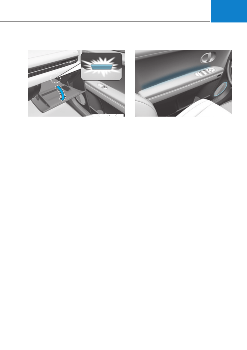
05
5-91
Glove box lamp
ONE1051068N
The glove box lamp turns on for about 20
minutes when the glove box is opened.
Door mood lamp
ONE1091026
ś Door mood lamp
To set the brightness and the color of
the door mood lamp, select ‘Setup
Ɵ9HKLFOH6HWWLQJVƟ/LJKWVƟ,QWHULRU
mood lamp’
ś When driving at night or under low
light driving conditions, the sensors
detect the light level around the
vehicle and automatically adjust the
brightness of the mood lamp.
To set the automatic brightness
adjustment turn On/Off, select ‘Setup
Ɵ9HKLFOH6HWWLQJVƟ/LJKWVƟ,QWHULRU
0RRG/DPSƟ%ULJKWQHVVFRQWUROŔ
ś There are different colors for different
drive modes.
To set the colors for the different
GULYHPRGHVVHOHFWœ6HWXSƟ9HKLFOH
6HWWLQJVƟ/LJKWVƟ,QWHULRU0RRG
/DPSƟ&RORUVIRUWKHGULYHPRGHVŔ
ś The color of the mood lamp turns
red when the vehicle speed exceeds
the speed limit in the speed control
section.
To set the color change function,
VHOHFWœ6HWXSƟ9HKLFOH6HWWLQJVƟ
/LJKWVƟ,QWHULRU0RRG/DPSƟ6SHHG
limit warning)’
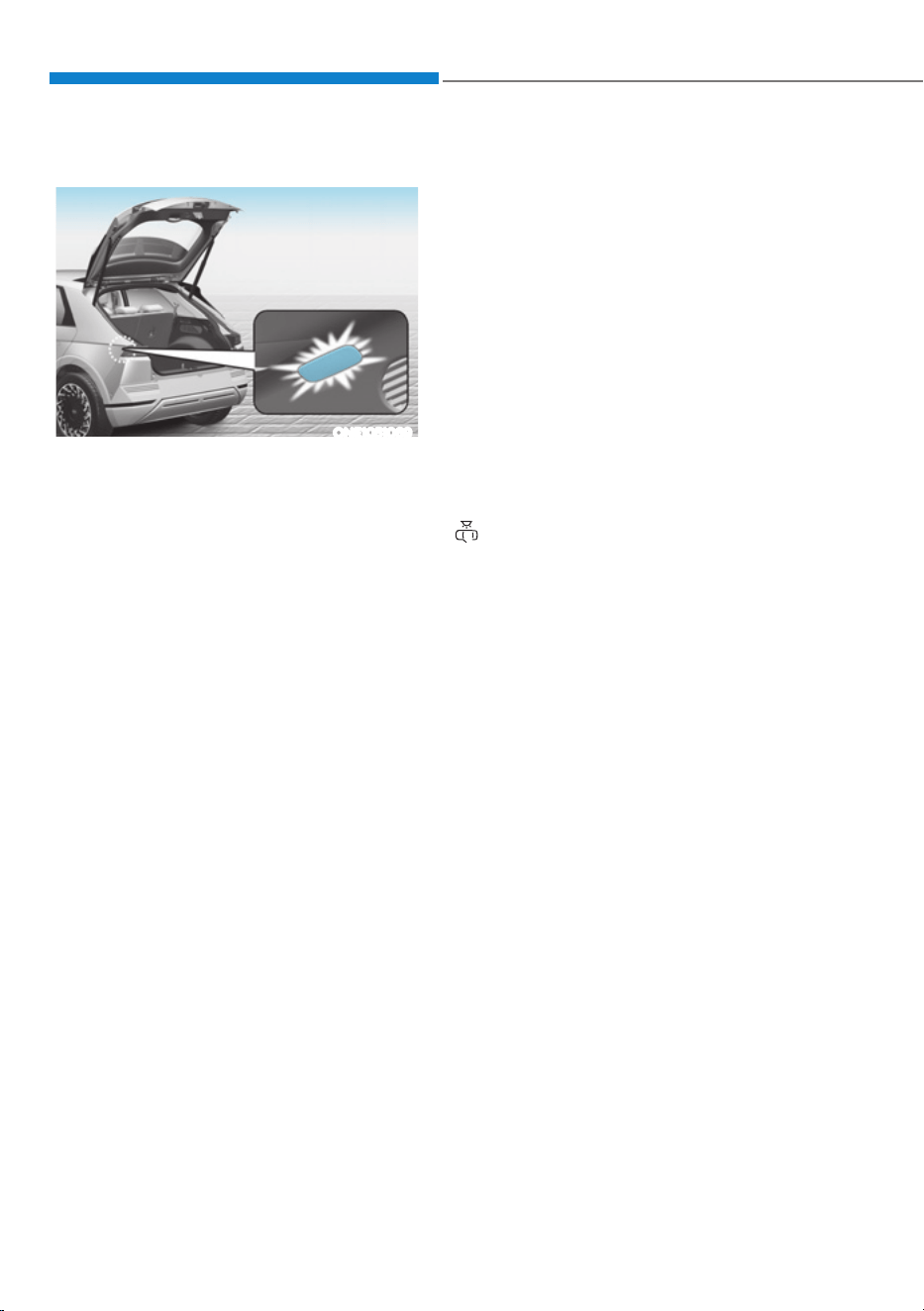
Convenience Features
5-92
Luggage compartment lamp
ONE1051069
The lamp turns on when the liftgate is
opened.
Headlamp and position lamp
When the light switch is ON, and all
the doors (and liftgate) are closed and
locked, the headlamp and position lamp
will turn on for approximately 15 seconds
if the door unlock button is pressed on
the smart key.
6HOHFWœ6HWXSƟ/LJKWVƟ+HDGOLJKW'HOD\Ŕ
from the Settings menu to turn on this
function.
For detailed information, refer to the
separately supplied infotainment
system manual.
Interior lamp
When the interior lamp switch is in the
position and all doors (and liftgate)
are closed and locked, the room lamp
will come on for 30 seconds if any of the
below is performed.
- When the door unlock button is
pressed on the smart key.
- When you touch the touch sensor on
the door handle while carrying the
smart key.
At this time, if you press the door lock
or unlock button on the smart key the
lamps will turn off immediately.
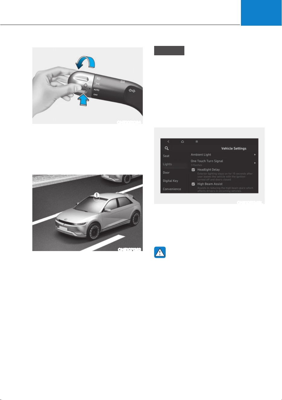
05
5-93
ONE1051064
High Beam Assist will automatically
adjust the headlamp range (switches
between high beam and low beam)
depending on the brightness of detected
vehicles and certain road conditions.
Detecting sensor
ONE1071262
[1] : front view camera
The front view camera is used as a
detecting sensor to detect ambient light
and brightness while driving.
Refer to the picture above for the
detailed location of the detecting sensor.
NOTICE
ś Always keep the front view camera in
good condition to maintain optimal
performance of High Beam Assist.
ś For more details on the precautions
of the front view camera, refer to
“Forward Collision-Avoidance Assist
(FCA)” section in chapter 7.
High Beam Assist Settings
Setting features
ONE1051248L
With the Start/Stop button in the ON
SRVLWLRQVHOHFWœ/LJKWVƟ+LJK%HDP
Assist’ from the Settings menu to turn on
High Beam Assist and deselect to turn off
the function.
WARNING
For your safety, change the Settings
after parking the vehicle at a safe
location.
+,*+%($0$66,67ǣ+%$Ǥǣ,)(48,33('Ǥ

Convenience Features
5-94
High Beam Assist Operation
Display and control
ś After selecting ‘High Beam Assist’
in the Settings menu, High Beam
Assist will operate by following the
procedure below.
- Place the headlamp switch in
the AUTO position and push
the headlamp lever towards the
instrument cluster. The High Beam
Assist (
) indicator light will
illuminate on the cluster and High
Beam Assist will be enabled.
- When High Beam Assist is enabled,
high beam will turn on when vehicle
speed is above 40 km/h (25 mph).
When vehicle speed is below 25
km/h (15 mph), high beam will turn
off.
- The High Beam (
) indicator light
will illuminate on the cluster when
high beam is on.
ś When High Beam Assist is operating, if
the headlamp lever or switch is used,
High Beam Assist operates as follow:
- If the headlamp lever is pulled
towards you when the high beam
is off, the high beam will turn on
without High Beam Assist canceled.
When you let go of the headlamp
lever, the lever will move to the
middle and the high beam will turn
off.
- If the headlamp lever is pulled
towards you when the high beam is
on by High Beam Assist, low beam
will turn on and the function will
turn off.
- If the headlamp switch is placed
from AUTO to another position
(headlamp/position/off), High
Beam Assist will turn off and the
corresponding lamp will turn on.
ś When High Beam Assist is operating,
high beam switches to low beam if
any of the following conditions occur:
- When the headlamp of an
oncoming vehicle is detected.
- When the tail lamp of a vehicle in
front is detected.
- When the headlamp or tail lamp of a
motorcycle or a bicycle is detected.
- When the surrounding ambient light
is bright enough that high beams
are not required.
- When streetlights or other lights are
detected.
Information
The images or colors may be displayed
differently depending on the specifications
of the instrument panel or theme.
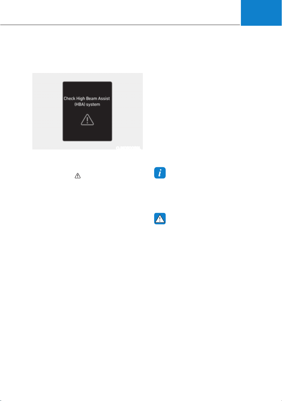
05
5-95
High Beam Assist Malfunction
and Limitations
High Beam Assist malfunction
OJK050059L
When High Beam Assist is not working
properly, the ‘Check High Beam Assist
(HBA) system’ warning message
will appear and
warning light will
illuminate on the cluster. Have the
function inspected by an authorized
HYUNDAI dealer.
Limitations of High Beam Assist
High Beam Assist may not work properly
in the following situations:
ś Light from an oncoming or front
vehicle is not detected because of
lamp damage, or because it is hidden
from sight, etc.
ś Headlamp of an oncoming or front
vehicle is covered with dust, snow or
water.
ś A front vehicle’s headlamps are off,
but the fog lamps are on, etc.
ś There is a lamp that has a similar
shape as a vehicle’s lamp.
ś Headlamps have been damaged or
not repaired properly.
ś Headlamps are not aimed properly.
ś Driving on a narrow curved road,
rough road, uphill or downhill.
ś Vehicle in front is partially visible on a
crossroad or curved road.
ś There is a traffic light, reflecting sign,
flashing sign or mirror ahead.
ś There is a temporary reflector or flash
ahead (construction area).
ś The road conditions are bad such as
being wet, iced or covered with snow.
ś A vehicle suddenly appears from a
curve.
ś The vehicle is tilted from a flat tire or
is being towed.
ś Light from an oncoming or front
vehicle is not detected due to
obstacles in the air such as exhaust
fume, smoke, fog, snow, or water spay
or blizzard on the road, or fogging in
the lamp, etc.
Information
For more details on the limitations of the
)URQW9LHZ&DPHUDUHIHUWR³)RUZDUG
&ROOLVLRQ$YRLGDQFH$VVLVW)&$´VHFWLRQ
in chapter 7.
WARNING
ś At times, High Beam Assist may not
work properly. High Beam Assist is
for your convenience only. It is the
responsibility of the driver for safe
driving practices and always check
the road conditions for your safety.
ś When High Beam Assist does
not operate properly, change
the headlamp position manually
between high beam and low beam.
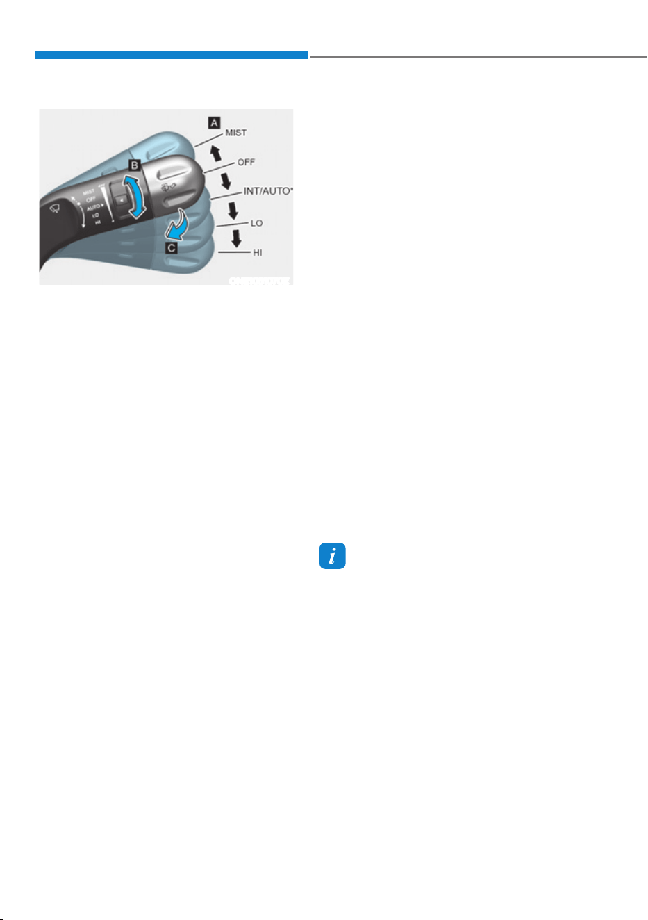
Convenience Features
5-96
:,3(56$1':$6+(56
ONE1051070E
A. Wiper speed control
śMIST – Single wipe
śOFF – Off
śINT – Intermittent wipe
AUTO* – Auto control wipe
śLO – Low wiper speed
śHI – High wiper speed
B. Intermittent wipe time adjustment/
Auto control wipe time adjustment*
C. Wash with brief wipes
* : if equipped
Front Windshield Wipers
Operates as follows when the Start/Stop
button is in the ON position.
MIST : For a single wiping cycle,
push the lever upward (or
downward) and release.
The wipers will operate
continuously if the lever is
held in this position.
OFF : Wiper is not in operation.
INT : Wiper operates intermittently
at the same wiping intervals.
To vary the speed setting, turn
the speed control knob (B).
AUTO : The rain sensor located on the
upper end of the windshield
glass senses the amount of
rainfall and controls the wiping
cycle for the proper interval.
The more it rains, the faster the
wiper operates. When the rain
stops, the wiper stops. To vary
the speed setting, turn the speed
control knob.
LO : The wiper runs at a lower speed.
HI : The wiper runs at a higher speed.
Information
If there is heavy accumulation of snow
or ice on the windshield, defrost the
windshield for about 10 minutes, or until
the snow and/or ice is removed before
using the windshield wipers to ensure
proper operation.
If you do not remove the snow and/or ice
before using the wiper and washer, it may
damage the wiper and washer system.
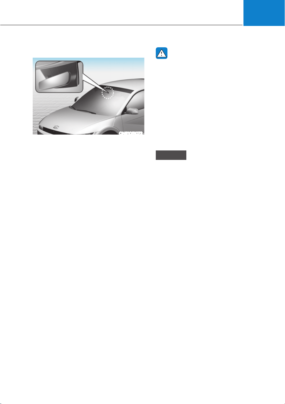
05
5-97
AUTO (Automatic) control
ONE1051072
The rain sensor located on the upper
end of the windshield glass senses
the amount of rainfall and controls the
wiping cycle for the proper interval.
The wiper operation time will be
automatically controlled depends on
rainfall.
When the rain stops, the wiper stops.
To vary the sensitivity setting, turn the
sensitivity control knob.
If the wiper switch is set in AUTO mode
when the Start/Stop button is in the ON
position, the wiper will operate once to
perform a self-check of the system. Set
the wiper to the OFF position when the
wiper is not in use.
WARNING
To avoid personal injury from the
windshield wipers, when the vehicle
is running and the windshield wiper
switch is placed in the AUTO mode:
ś Do not touch the upper end of the
windshield glass facing the rain
sensor.
ś Do not wipe the upper end of the
windshield glass with a damp or wet
cloth.
ś Do not put pressure on the
windshield glass.
NOTICE
ś When washing the vehicle, set the
wiper switch in the OFF position to
stop the auto wiper operation. The
wiper may operate and be damaged
if the switch is set in the AUTO mode
while washing the vehicle.
ś Do not remove the sensor cover
located on the upper end of the
passenger side windshield glass.
Damage to system components
could occur and may not be covered
by your vehicle warranty.
ś Because of using a photo sensor,
temporary malfunction could occur
according to sudden ambient light
change made by stone and dust
while driving.
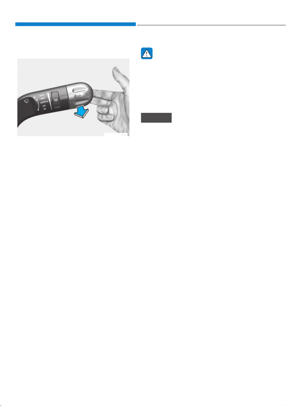
Convenience Features
5-98
Front Windshield Washers
ONE1051073
In the OFF position, pull the lever gently
toward you to spray washer fluid on the
windshield and to run the wipers 1-3
cycles. The spray and wiper operation
will continue until you release the lever. If
the washer does not work, you may need
to add washer fluid to the washer fluid
reservoir.
Recirculating air when washer fluid
is used
When washer fluid is used, in order to
reduce any objectionable scent of the
washer fluid from entering the cabin,
recirculation mode and air conditioning
are automatically activated depending
on the outside temperature. If you
select fresh mode while the function is
operating, the function will resume after
a certain amount of time. It may not work
in some conditions such as cold weather
or vehicle OFF.
For more details, refer to “Climate
Control Additional Features” section in
this chapter.
WARNING
When the outside temperature is below
freezing, ALWAYS warm the windshield
using the defroster to help prevent
the washer fluid from freezing on the
windshield and obscuring your vision
which could result in an accident and
serious injury or death.
NOTICE
ś To prevent possible damage to the
washer pump, do not operate the
washer when the fluid reservoir is
empty.
ś To prevent possible damage to the
wipers or windshield, do not operate
the wipers when the windshield is
dry.
ś To prevent damage to the wiper
arms and other components, do
not attempt to move the wipers
manually.
ś To prevent possible damage to the
wipers and washer system, use anti-
freezing washer fluids in the winter
season or cold weather.
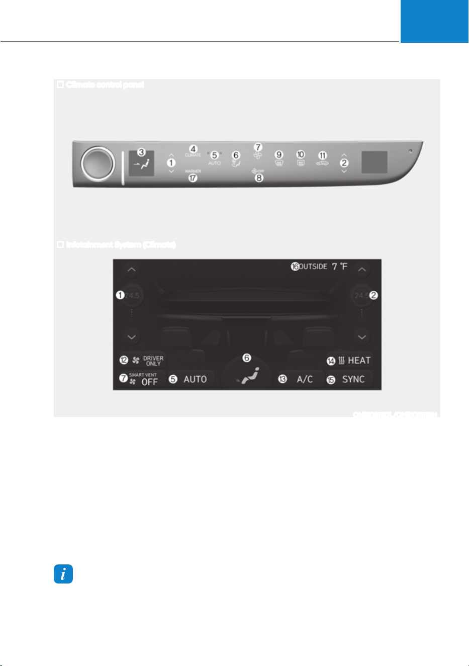
05
5-99
Information
Use a clean soft microfiber cloth to gently wipe any finger prints off the touch screen.
Climate control panel
Infotainment System (Climate)
The actual shape may differ from the illustration.
ONE1051127L/ONE1051115N
$8720$7,&&/,0$7(&21752/6<67(0
1. Driver’s temperature control
2. Passenger’s temperature control
3. Display the air flow direction
4. View climate infotainment screen
5. AUTO (automatic control)
6. Mode selection button
7. Fan speed up
8. Fan speed down / OFF
9. Front windshield defroster
10.
Rear windshield defroster
11.
Air intake control
12.
Driver only mode
13.
A/C (air conditioning) ON/OFF
14.
Heating ON/OFF
15.
SYNC
16.
Ambient temperature display
17.
Seat warmer/air ventilation
infotainment screen
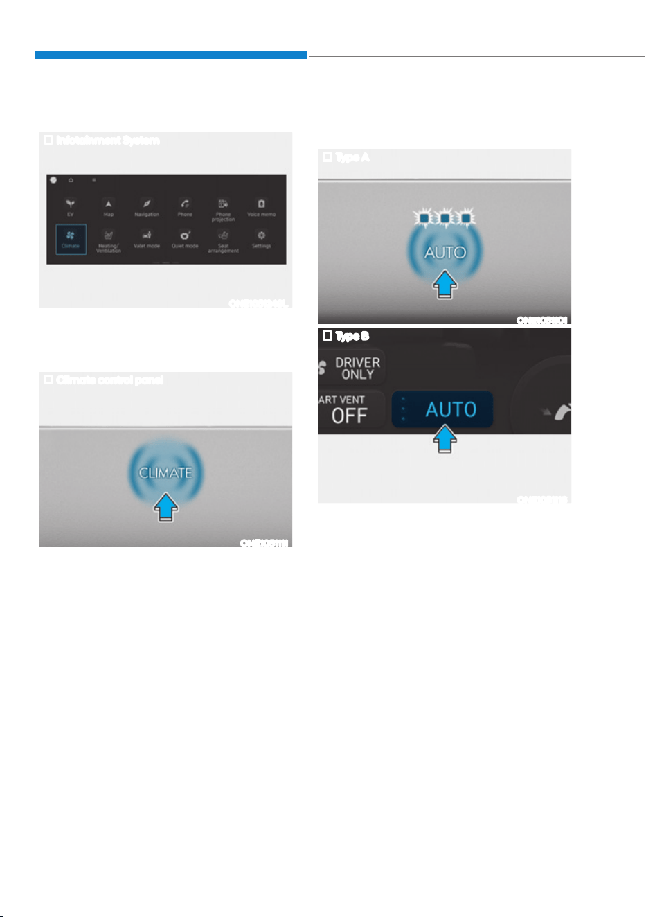
Convenience Features
5-100
Climate
Infotainment System
ONE1051249L
To view the climate information screen,
select Climate in the main infotainment
screen when the vehicle is ON.
Climate control panel
ONE1051111
Touch CLIMATE icon to view the climate
information in the infotainment screen.
Automatic Temperature Control
Mode
Type A
ONE1051101
Type B
ONE1051116
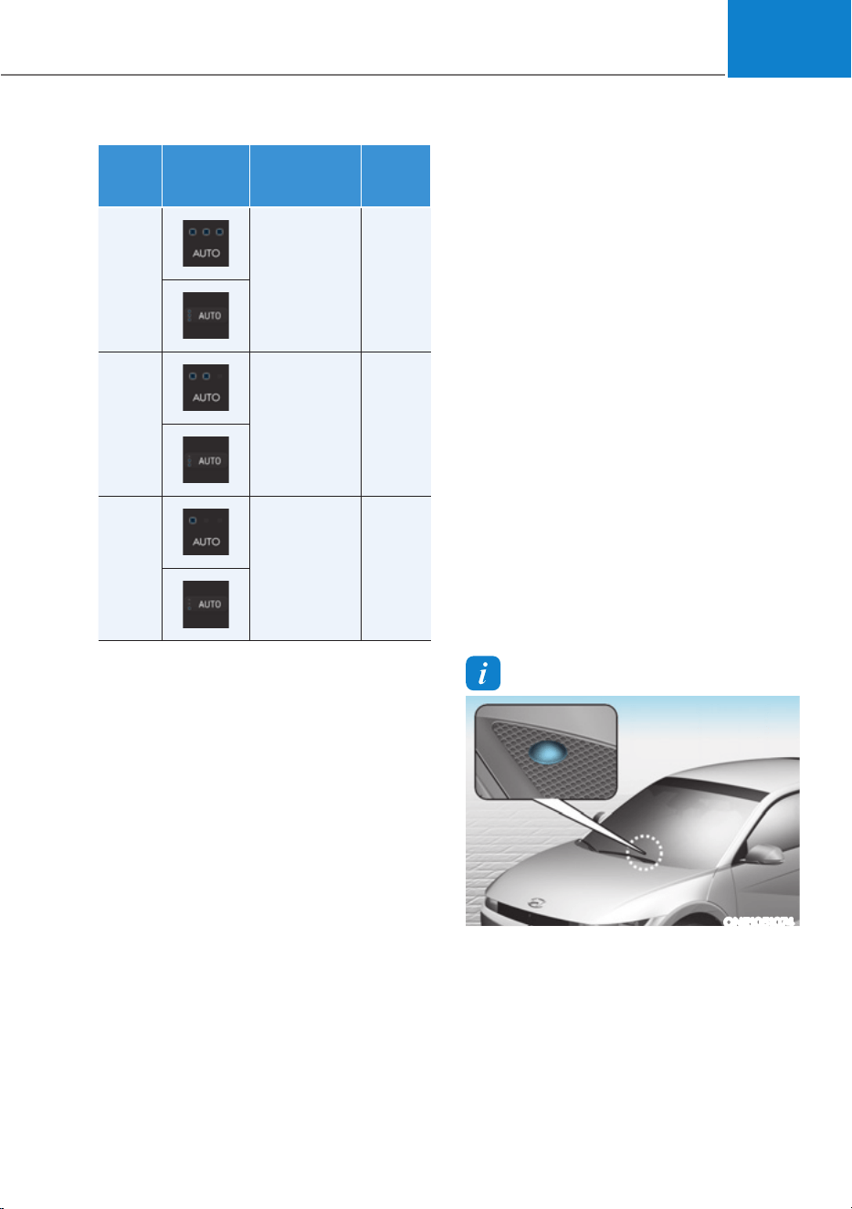
05
5-101
Level
AUTO
Indicator
Climate
Information
Fan
Speed
level
3 HIGH 1~8
2 MEDIUM 1~6
1 LOW 1~4
1. Press AUTO icon or touch the AUTO
icon in the infotainment screen to
select the fan speed (level1~3)
2. Adjust the temperature with the
temperature control icon.
The fan speed level only can be changed
manually.
The following systems can be
respectively adjusted while the AUTO
climate control is On. When those
systems are adjusted, AUTO indicator
lights will turn off.
- Fan speed level
- A/C (Air condition)
- Mode selection
- Front windshield defroster (When
defroster is turned off, AUTO
indicator light will illuminate)
For your convenience and to improve the
efficiency of the climate control, use the
AUTO button and set the temperature to
72°F (22°C).
To change the temperature unit from °C
to °F or °F to °C:
6HOHFWœ6HWXSƟ*HQHUDO6HWWLQJVƟ8QLW
Ɵ7HPSHUDWXUH8QLWƟr&r)ŔIURPWKH
Settings menu in the infotainment
system screen.
Information
ONE1051074
Never place anything near the ambient
light/solar sensor to ensure better control
of the heating and cooling system.
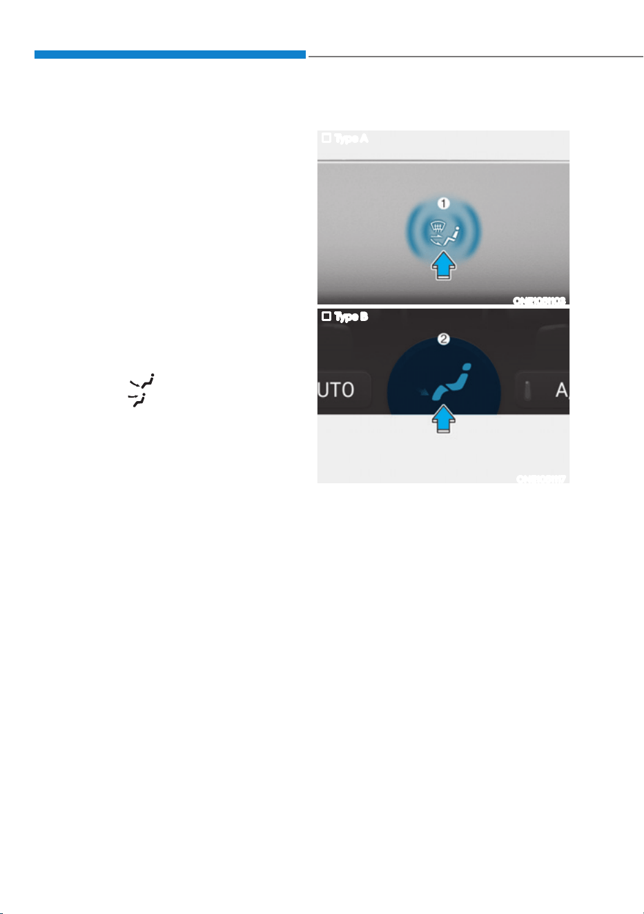
Convenience Features
5-102
Manual Temperature Control
Mode
The heating and cooling system can
be controlled manually by selecting
functions other than AUTO. In this case,
the system works sequentially according
to the order of the functions selected.
When selecting any other functions
except AUTO while using automatic
operation, the functions not selected will
be controlled automatically.
1. Start the vehicle.
2. Set the mode to the desired position.
To improve the effectiveness of
heating and cooling, select the mode
according to the following:
- Heating:
- Cooling:
3. Set the temperature control to the
desired value.
4. Set the air intake control to Fresh or
Recirculation mode.
5. Set the fan speed control to the
desired speed.
6. If air conditioning is desired, turn the
air conditioning system on.
7. Select AUTO to revert back to full
automatic control of the system.
Mode selection
Type A
ONE1051103
Type B
ONE1051117
Air flow direction
Touch the air flow direction icon (1) or (2)
in the infotainment screen to select the
desired air flow direction. The selected
air flow direction will be displayed on the
infotainment screen.
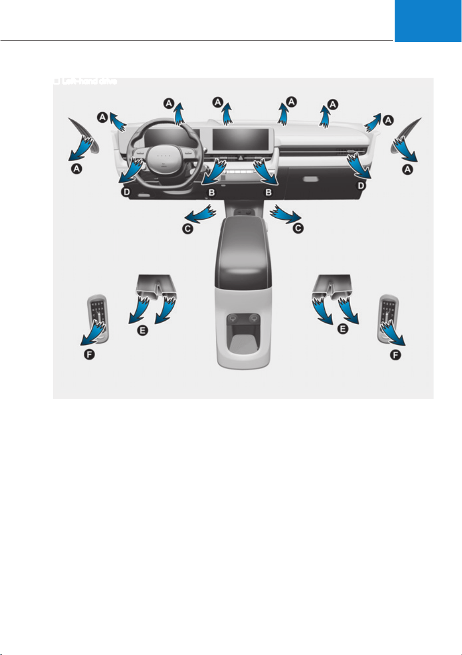
05
5-103
Left-hand drive
ONE1051104
Air flow direction
The mode selection Icon or button controls the direction of the air flow through the
ventilation system.
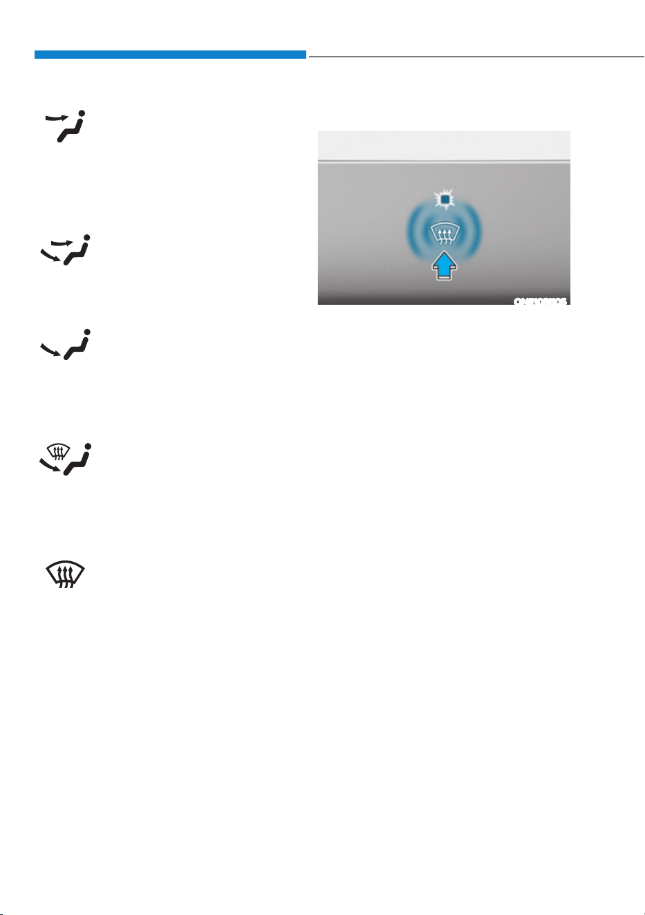
Convenience Features
5-104
Face-Level (B, D, F)
Air flow is directed toward the upper
body and face. Additionally, each outlet
can be controlled to direct the air
discharged from the outlet.
Bi-Level (B, D, C, E, F)
Air flow is directed towards the face and
the floor.
Floor-Level (A, C, D, E)
Most of the air flow is directed to the
floor, with a small amount of the air
being directed to the windshield and side
window defrosters.
Floor/Defrost-Level
(A, C, D, E)
Most of the air flow is directed to the
floor and the windshield with a small
amount directed to the side window
defrosters.
Defroster-Level (A, D)
Most of the air flow is directed to the
windshield with a small amount of air
directed to the side window defrosters.
Front windshield defroster
ONE1051105
Defrost-level (A, D)
Press the icon, and the indicator light will
illuminate and the windshield defroster
indicator will appear on the climate
control panel.
Most of the air flow is directed to the
windshield with a small amount of air
directed to the side window defrosters.
When Defogging logic is enabled, Fresh
mode is selected and air conditioning
is selected according to outside
temperature.
If the icon is pressed again, the indicator
light will turn off and the previous
settings will be selected.
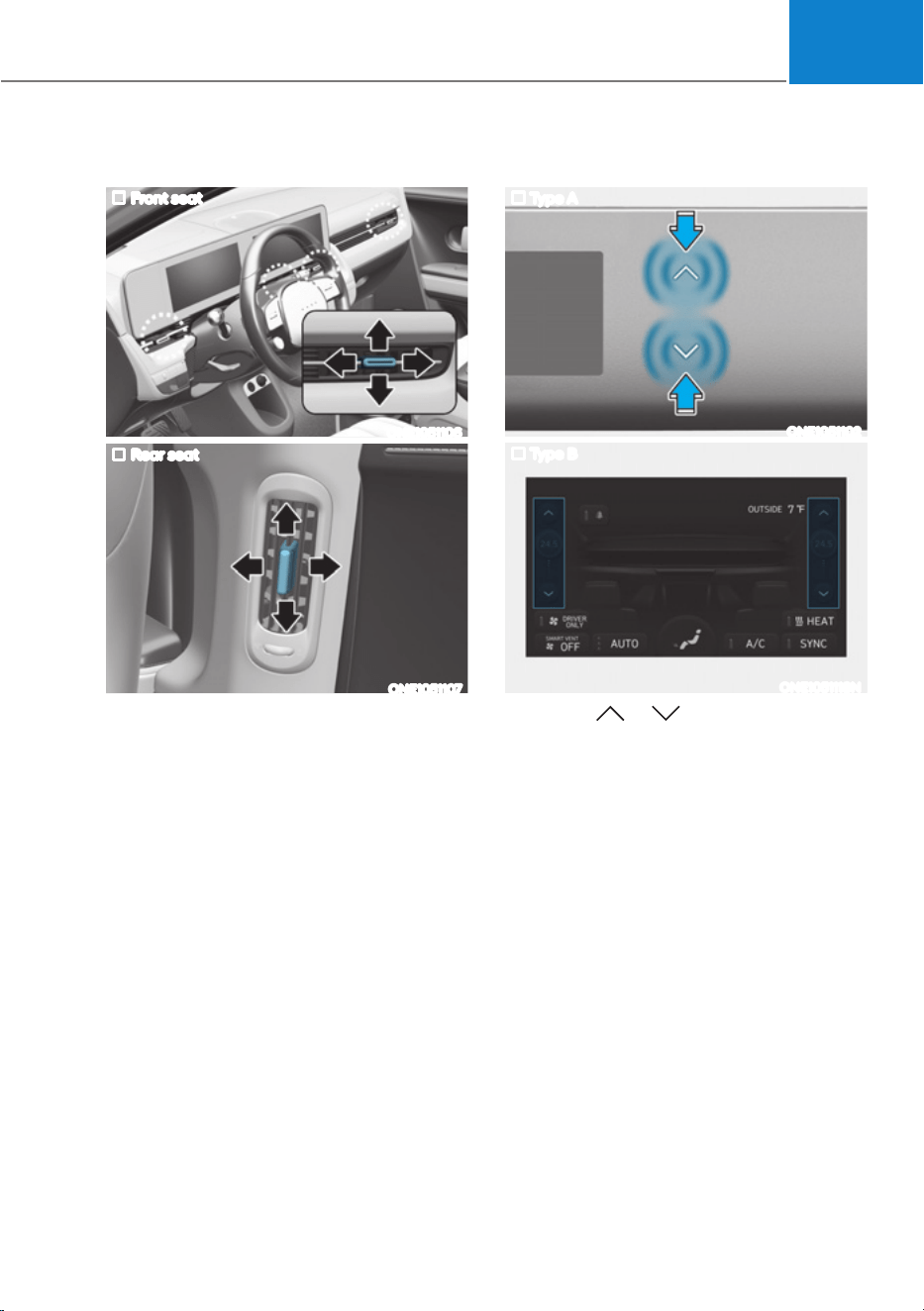
05
5-105
Instrument panel vents
Front seat
ONE1051106
Rear seat
ONE1051107
The instrument panel vent air flow can be
directed up/down or left/right using the
vent adjustment lever.
The air flow can also be CLOSED using
the vent adjustment lever.
Front seat
ś Move the lever away horizontally
from the seat to close until the levers
click and lock. Slightly move the lever
toward the seating position to unlock
and open.
Rear seat
ś Move the lever downward to close
the air flow. Move the lever upward to
open. the air flow.
Temperature control
Type A
ONE1051102
Type B
ONE1051118N
Touch the or icon to select the
temperature.
The temperature can be increased or
decreased by increments of 1°F (0.5°C)
for each incremental location. When set
to the lowest temperature setting, the air
conditioning will operate continuously
to quickly cool the interior of the vehicle
initially. After interior temperature has
been cooled down sufficiently, select
AUTO and set the temperature to 72 °F
(22 °C).
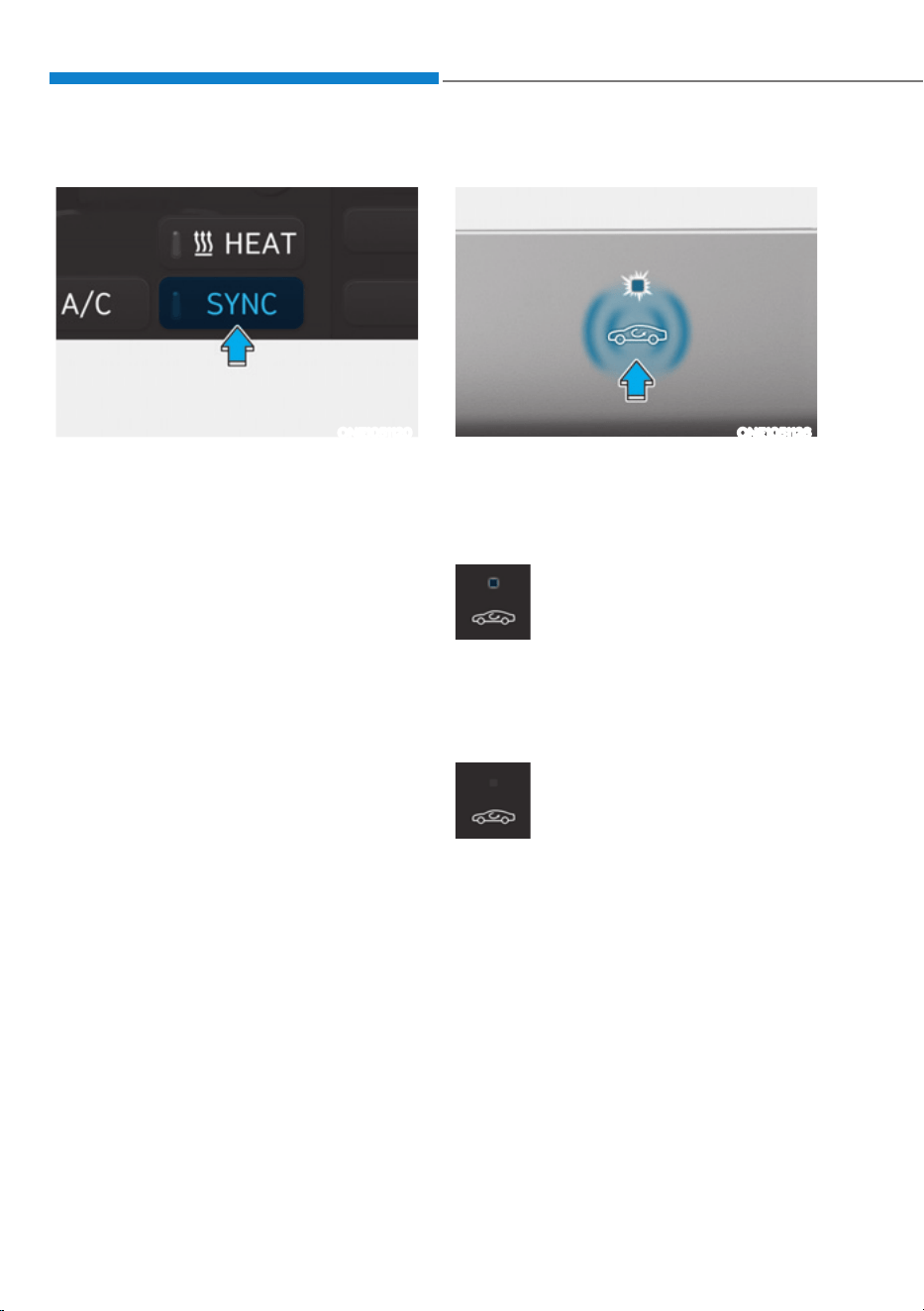
Convenience Features
5-106
SYNC
ONE1051120
Adjusting the temperature and air flow
direction equally
Press SYNC (indicator light ON), the
passenger’s temperature and air flow
direction will be adjusted same as the
driver’s control.
Adjusting the temperature and air flow
direction individually
Press SYNC (indicator light OFF), all seats
temperature and air flow direction will be
adjusted individually.
Air intake control
ONE1051126
Air intake control is used to select either
Fresh mode (outside air) or Recirculation
mode (cabin air).
Recirculation mode
When Recirculation mode
is selected, air from the
passenger compartment will
be recirculated through the
system and heated or cooled
according to the function
selected.
Fresh mode
When Fresh mode is selected,
air enters the vehicle from
outside and is heated or
cooled according to the
function selected.
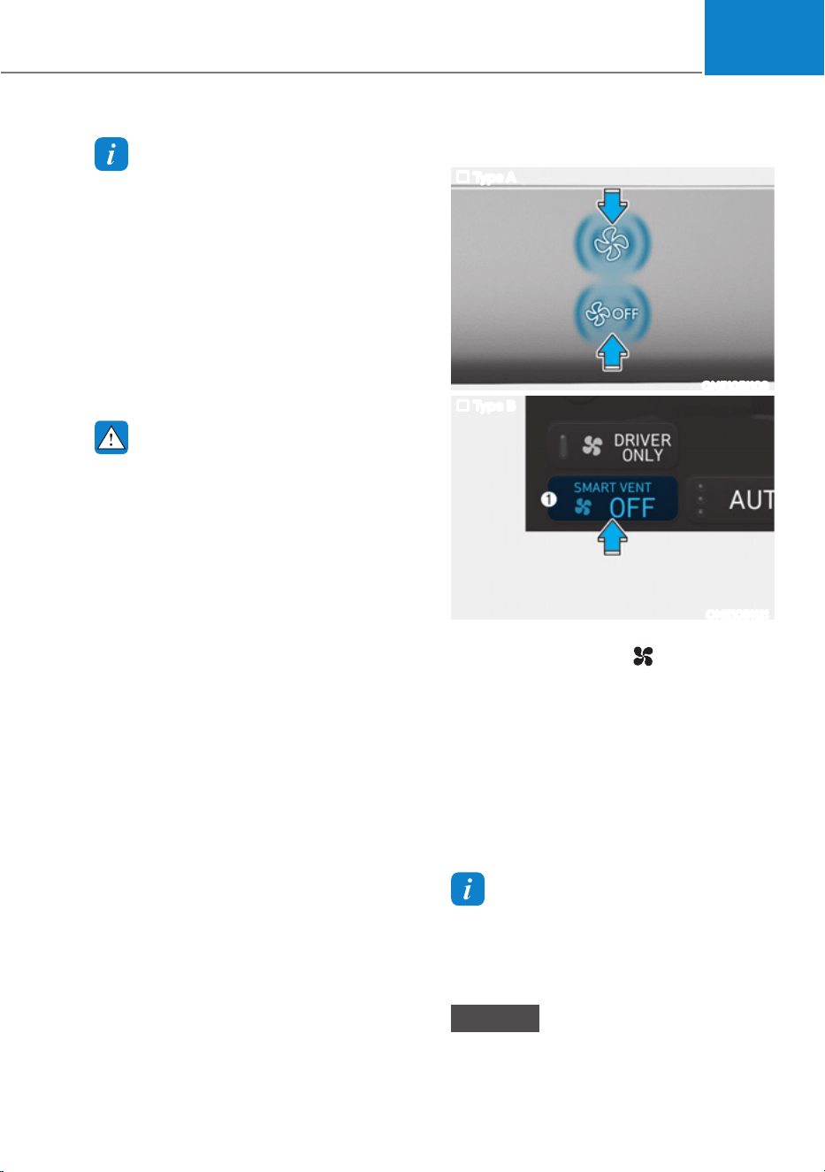
05
5-107
Information
Operating the system primarily in Fresh
mode is recommended. Use Recirculation
mode temporarily only when needed.
3URORQJHGRSHUDWLRQRIWKHKHDWHULQ
Recirculation mode and without the air
conditioning ON can cause fogging of the
windshield. In addition, prolonged use of
the air conditioning ON in Recirculation
mode may result in excessively dry,
dehumidified air in the cabin and may
promote formation of musty vent odor due
to stagnant air.
WARNING
ś Continued use of the climate control
system operation in Recirculation
mode for a prolonged period of
time may cause drowsiness to the
occupants in the cabin. This may lead
to loss of vehicle control which may
lead to an accident.
ś Continued use of the climate control
system operation in Recirculation
mode with the air conditioning OFF
may allow humidity to increase
inside the cabin. This may cause
condensation to accumulate on the
windshield and obscure visibility.
ś Do not sleep in your vehicle or
remain parked in your vehicle with
the windows up and either the
heater or the air conditioning ON for
prolonged periods of time. Doing so
may increase the levels of carbon
dioxide in the cabin which may lead
to serious injury or death.
Fan speed control
Type A
ONE1051109
Type B
ONE1051121
The fan speed can be set to the desired
speed by adjusting the
icon in the
climate control panel.
More air is delivered with higher fan
speeds.
Pressing the OFF icon or button turns off
the fan.
You can check the fan speed and auto
air circulation mode in the climate
information screen icon (1) in the
infotainment system.
Information
To help improve microphone voice input
sound, fan speed may automatically slow
down for a couple of minutes when you
activate voice recognition or hands free.
NOTICE
Operating the fan when the Start/Stop
button is in the OFF position could cause
the battery to discharge. Operate the fan
when the vehicle is running.
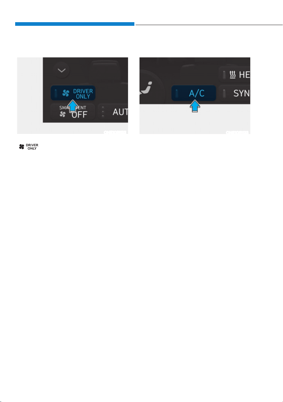
Convenience Features
5-108
Driver only
ONE1051122
If you touch the DRIVER ONLY icon
(
) and the indicator light
illuminates in the infotainment climate
control screen, cold air mostly blows
in the driver’s seat. However, some
of the cold air may come out of other
seating position ducts to keep indoor air
pleasant.
If you use the icon with no passenger
in the front passenger seat, energy
consumption will be reduced.
DRIVER ONLY icon will be turned off
under the following conditions:
1) Defrost on
2) DRIVER ONLY button re-touch
Air conditioning
ONE1051123
Touch the CLIMATE icon in the climate
control panel. The climate information
screen will appear on the infotainment
screen. Touch the A/C icon in the
infotainment screen to turn the air
conditioning on (indicator light ON) and
off.

05
5-109
HEAT icon
ONE1051124
Touch CLIMATE icon in the climate
control panel. The climate information
screen will appear on the infotainment
screen. Touch the HEAT icon in the
infotainment screen to turn the heater on
(indicator light will illuminate).
Touch the button again to turn the heater
off.
The air conditioner and heater uses
energy from the battery. If you use the
heater or air conditioner for too long,
distance to empty can be reduced due to
too much power consumption.
Turn off the heater and air conditioner if
you do not need them.
OFF mode
ONE1051110
Touch the OFF icon to turn the climate
control system off. You can still operate
mode selection and air intake control as
long as the Start/Stop button is in the ON
position.

Convenience Features
5-110
System Operation
Cooling / Ventilation
1. Select the Face Level ( ) mode in the
infotainment screen.
2. Set the air intake control to fresh or
recirculation mode.
3. Set the temperature to the desired
position.
4. Set the fan speed to the desired
speed.
Heating
1. Select the Floor Level ( ) mode in
the infotainment screen.
2. Set the air intake control to fresh or
recirculation mode.
3. Set the temperature to the desired
position.
4. Set the fan speed to the desired
speed.
5. If desired, turn the air conditioning ON
with the temperature set high in order
to dehumidify the air before it enters
into the cabin.
If the windshield fogs up, select the Front
Defrost (
) mode.
Operation Tips
ś To keep dust or unpleasant fumes
from entering the vehicle through the
ventilation system, temporarily set the
air intake control to the recirculation
mode. Return the control to the
Recirculation mode to the Fresh mode
when the unpleasant air outside has
diminished. This will help keep the
driver alert and comfortable.
ś To help prevent the inside of the
windshield from fogging, set the air
intake control to fresh mode and the
fan speed to the desired position, turn
on the air conditioning system, and
adjust the temperature control to the
desired temperature.
Air conditioning
Your HYUNDAI Vehicle air conditioning
system is filled with R-1234yf refrigerant.
1. Touch the [CLIMATE] icon to display
climate information the infotainment
screen.
2. Select A/C icon (indicator light ON)
in the climate information screen to
activate the air-condition.
3. Set the temperature low.
4. Set the direction of air flow by
touching the mode selection icon.
5. Touch the HEAT icon (indicator light
OFF) to turn on the air-condition.
When maximum cooling is desired, set
the temperature to the lowest position,
then set the fan speed control to the
highest setting.
Air conditioning system operation tips
ś If the vehicle has been parked in
direct sunlight during hot weather,
open the windows for a short time
to let the hot air inside the vehicle
escape.
ś After sufficient cooling has been
achieved, switch back from
recirculation mode to fresh mode.
ś To help reduce moisture inside of
the windows on rainy or humid
days, decrease the humidity inside
the vehicle by operating the air
conditioning system with the windows
and vision roof closed.
ś Use the air conditioning system
every month only for a few minutes
to ensure maximum system
performance.
ś If you operate air conditioner
excessively, the difference between
the temperature of the outside air and
that of the windshield could cause
the outer surface of the windshield to
fog up, causing loss of visibility. In this
case, set the mode selection to the
position and fan speed control to the
lowest speed.
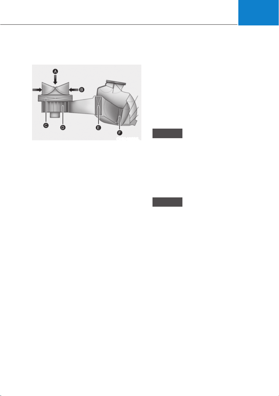
05
5-111
System Maintenance
Cabin air filter
OHI048581L
[A] : Outside air, [B] : Recirculated air
[C] : Cabin air filter, [D] : Blower
[E] : Evaporator core, [F] : PTC & Inner condenser
The cabin air filter is installed behind the
front trunk. It filters the dust or other
pollutants that enter the vehicle through
the heating and air conditioning system.
Have the cabin air filter replaced by an
authorized HYUNDAI dealer according to
the maintenance schedule. If the vehicle
is being driven in severe conditions such
as dusty or rough roads, more frequent
cabin air filter inspections and changes
are required.
If the air flow rate suddenly decreases,
have the system inspected at an
authorized HYUNDAI dealer.
Checking the amount of air
conditioner refrigerant and
compressor lubricant
When the amount of refrigerant is low,
the performance of the air conditioning
is reduced. Overfilling also reduces the
performance of the air conditixoning
system.
Therefore, if abnormal operation is
found, have the system inspected by an
authorized HYUNDAI dealer.
NOTICE
It is important that the correct type and
amount of oil and refrigerant is used.
Otherwise, damage to the compressor
and abnormal system operation may
occur. To prevent damage, the air
conditioning system in your vehicle
should only be serviced by trained and
certified technicians.
NOTICE
The refrigerant system should only
be serviced by trained and certified
technicians to insure proper and safe
operation.
The refrigerant system should be
serviced in a well-ventilated place.
The air conditioning evaporator (cooling
coil) shall never be repaired or replaced
with one removed from a used or
salvaged vehicle and new replacement
MAC evaporators shall be certified
(and labeled) as meeting SAE Standard
J2842.
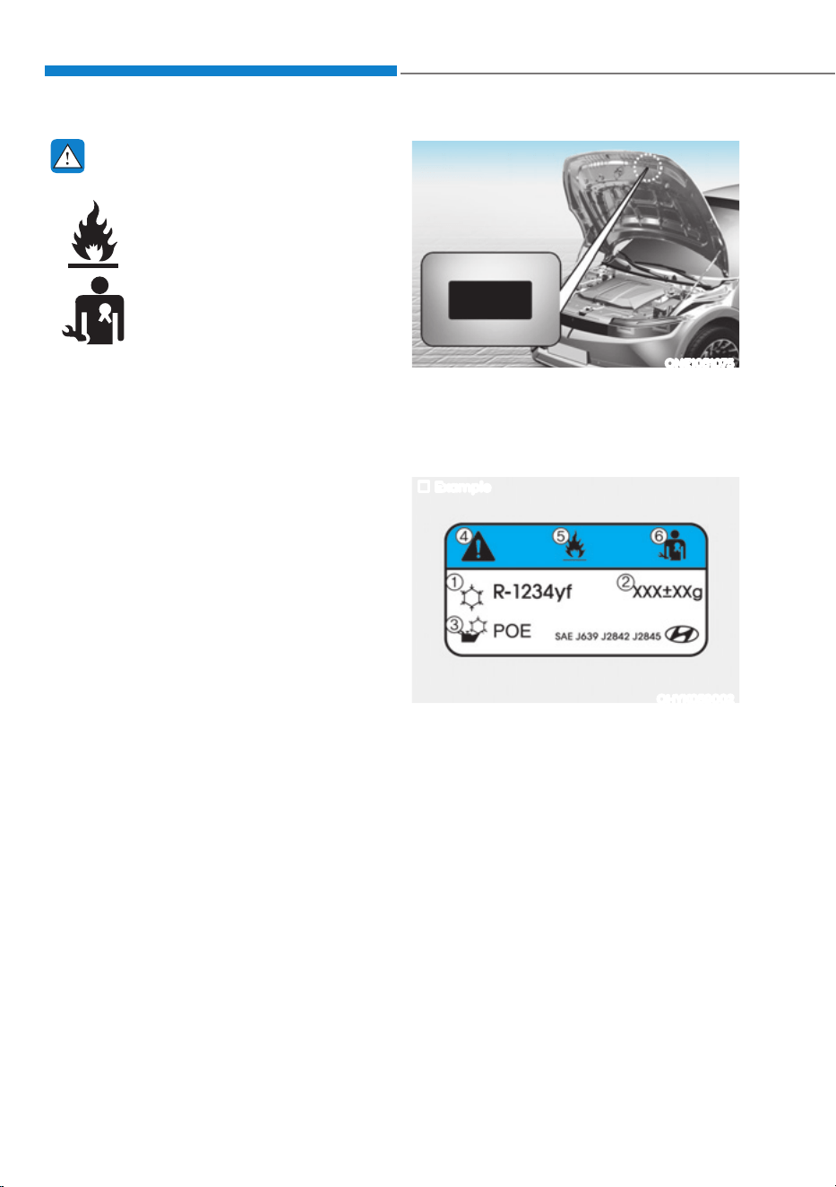
Convenience Features
5-112
WARNING
Vehicles equipped with R-1234yf
Since the refrigerant is
mildly flammable and
operated at high pressure,
the air conditioning system
should only be serviced
by trained and certified
technicians. It is important
that the correct type and
amount of oil and refrigerant
are used.
All refrigerants should be reclaimed
with proper equipment.
Venting refrigerants directly to the
atmosphere is harmful to individuals
and environment. Failure to heed these
warnings can lead to serious injuries.
ONE1051075
Air Conditioning refrigerant label
You can find out which air conditioning
refrigerant is applied to your vehicle on
the label located inside of the hood.
Example
OHYK059002
Each symbol and specification on the
air conditioning refrigerant label is
represented as below:
1. Classification of refrigerant
2. Amount of refrigerant
3. Classification of compressor lubricant
4. Caution
5. Flammable refrigerant
6. To require registered technician to
service air conditioning system
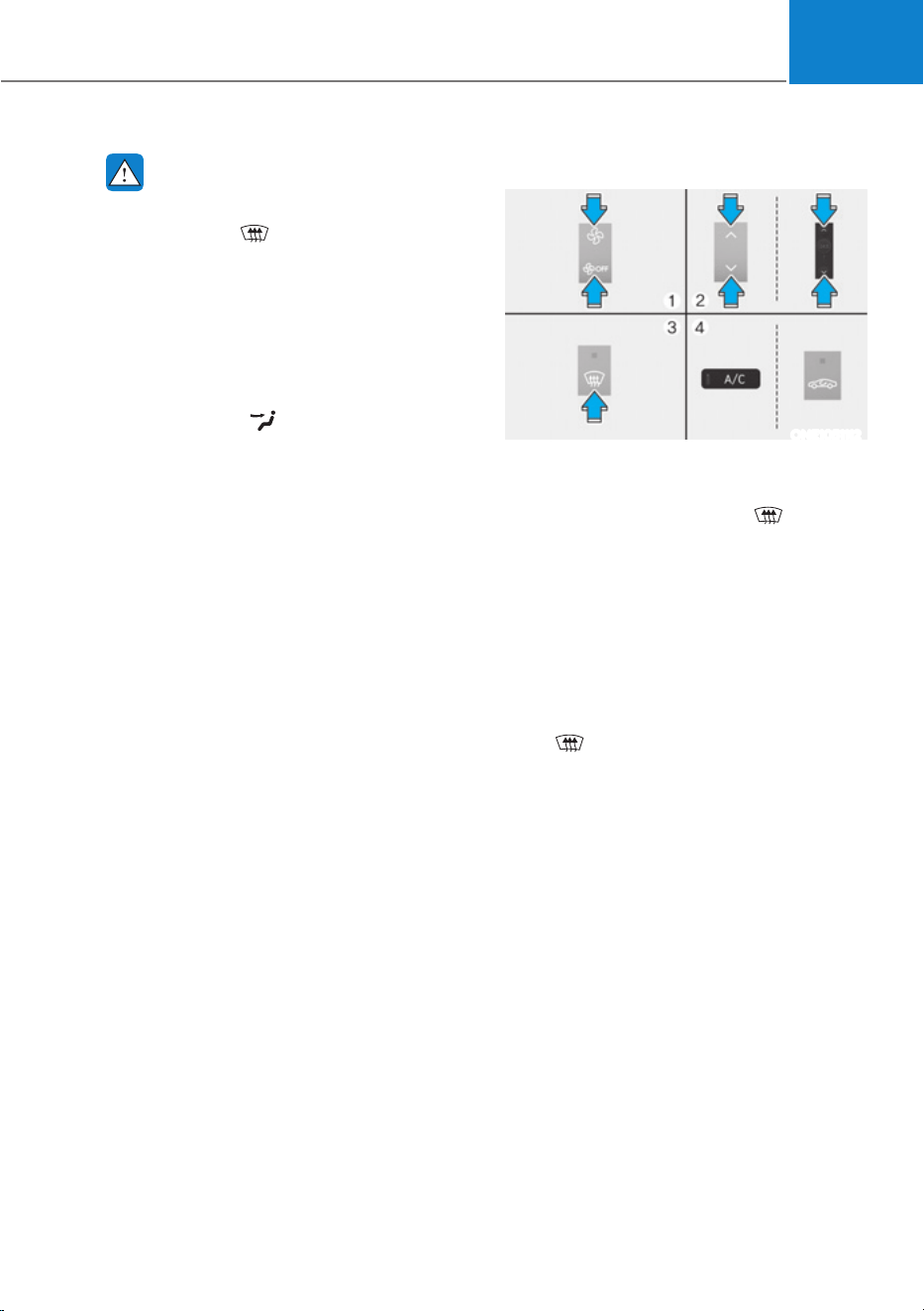
05
5-113
WINDSHIELD DEFROSTING AND DEFOGGING
WARNING
Windshield heating
Do not use the
position during
cooling operation in extremely humid
weather. The difference between the
temperature of the outside air and that
of the windshield could cause the outer
surface of the windshield to fog up,
causing loss of visibility could cause
an accident resulting in serious injury
or death. In this case, set the mode
selection to the
position and fan
speed control to a lower speed.
ś For maximum defrost performance,
set the temperature control to the
highest temperature setting and
the fan speed control to the highest
setting.
ś If warm air to the floor is desired while
defrosting or defogging, set the mode
to the floor-defrost position.
ś Before driving, clear all snow and ice
from the windshield, rear window,
outside rearview mirrors, and all side
windows.
ś Clear all snow and ice from the
hood and air inlet in the cowl grill
to improve heater and defroster
efficiency and to reduce the
probability of fogging up the inside of
the windshield.
To Defog Inside Windshield
ONE1051112
1. Select the desired fan speed.
2. Select the desired temperature.
3. Touch the defroster icon (
).
4. When the defogging logic is enabled,
Fresh mode is selected and air
conditioning is selected according to
outside temperature.
Check to make sure the air intake control
is in Fresh mode. If the air intake control
indicator light is illuminated, touch
the icon once to enable Fresh mode
(indicator light OFF).
If the
position is selected, the fan
speed is automatically increased.
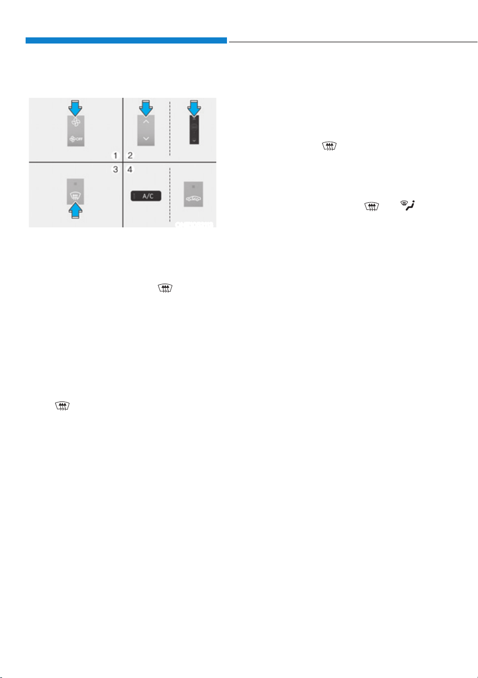
Convenience Features
5-114
To Defrost Outside Windshield
ONE1052113
1. Set the fan speed to the highest
position.
2. Set the temperature to the extreme
hot position.
3. Touch the defroster icon (
).
4. When Defogging logic is enabled,
Fresh mode is selected and air
conditioning is selected according to
outside temperature.
Check to make sure the air intake control
is in Fresh mode. If the air intake control
indicator light is illuminated, touch
the icon once to enable Fresh mode
(indicator light OFF).
If the
position is selected, lower fan
speed is adjusted to a higher fan speed.
Defogging Logic
To reduce the probability of fogging
up the inside of the windshield, the air
intake or air conditioning are controlled
automatically according to certain
conditions such as
positions. To
cancel or reset the defogging logic, do
the following.
1. Press the Start/Stop button to the ON
position.
2. Touch the defroster icon (
) or ( ).
3. While touching the A/C icon, touch
the air intake control icon at least 5
times within 3 seconds.
The air intake control indicator will blink
3 times to indicate that the defogging
logic has been disabled. Repeat the steps
again to re-enable the defogging logic.
The air intake control indicator will blink
6 times to indicate that the defogging
logic has been enabled.
If the battery has been discharged or
disconnected, it resets to the defog logic
status.
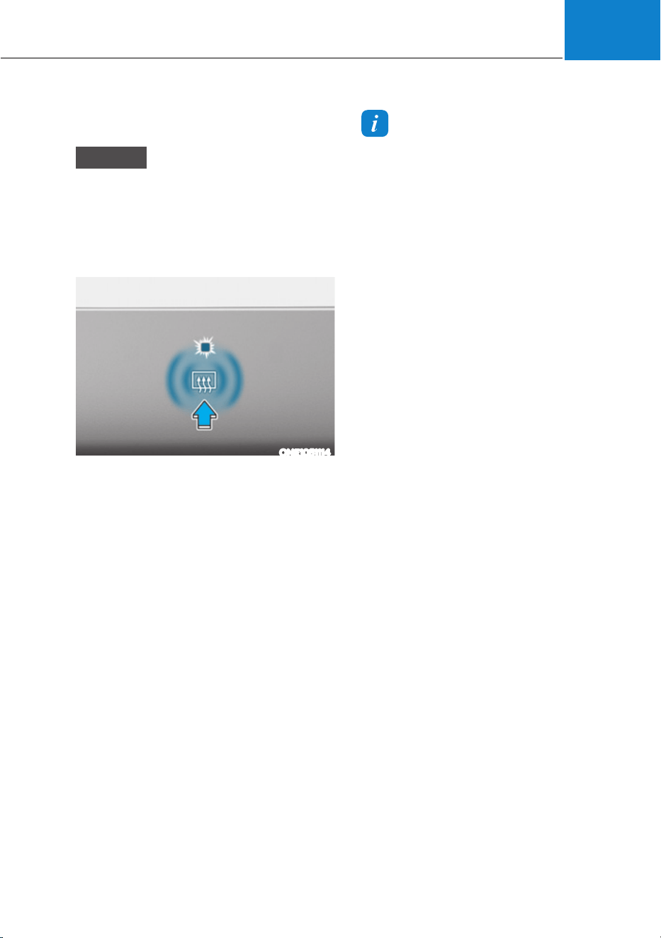
05
5-115
Rear Window Defroster
NOTICE
To prevent damage to the rear window
defroster conducting elements bonded
to the inside surface of the rear window,
never use sharp instruments or window
cleaners containing abrasives to clean
the window.
ONE1051114
The defroster heats the window to
remove frost, fog and thin ice from the
interior and exterior of the rear window,
while the vehicle is running.
ś To activate the rear window defroster,
touch the rear window icon located
in the center control panel. The
indicator on the rear window defroster
illuminates when the defroster is on.
ś To turn off the defroster, touch the
rear window defroster button again.
Information
ś If there is heavy accumulation of snow
on the rear window, brush it off before
operating the rear defroster.
ś The rear window defroster
automatically turns off after
approximately 20 minutes or when
the Start/Stop button is in the OFF
position.
Outside rearview mirror defroster
If your vehicle is equipped with the
rearview mirror defrosters, they will
operate at the same time you turn on the
rear window defroster.

Convenience Features
5-116
A/C Automatic Drying (if
equipped)
A/C Automatic Drying feature dries
the moisture in the air conditioner and
reduces air conditioner odor. The blower
motor automatically operates after 30
minutes the vehicle is turned off.
Turning A/C Automatic Drying On or
off
The A/C Automatic Drying feature can
be turned on and off by selecting ‘Setup
Ɵ9HKLFOH6HWWLQJVƟ&OLPDWHƟ&OLPDWH
)HDWXUHVƟ$&$XWRPDWLF'U\LQJŔIURP
the infotainment system. See additional
information in supplied Infotainment
Manual.
If the operating condition is satisfied
after setting the feature, the operating
condition is displayed on the
infotainment system screen and the
blower motor automatically operates.
When the A/C Automatic Drying feature
is activated, the air conditioner sets the
fan speed to the third level, selects Fresh
mode, and directs the air flow to the
floor.
Operating conditions
The A/C Automatic Drying feature
operates under the following conditions:
The vehicle is turned off after operating
the air conditioner for a certain period
The 12-volt battery level is sufficient The
outside temperature is above a certain
level
Non-operating conditions
The A/C Automatic Drying feature stops
operating under the following conditions:
- The A/C Automatic Drying feature has
operated for 3 minutes
- The Start/Stop button is pressed, or
the vehicle is on
- The climate control system is
operated remotely
Information
ś The A/C Automatic Drying feature
reduces air conditioner odors but may
not remove all odors.
ś The A/C Automatic Drying feature does
not operate if the remaining battery
level is insufficient to prevent battery
discharge.
&/,0$7(&21752/$'',7,21$/)($785(6
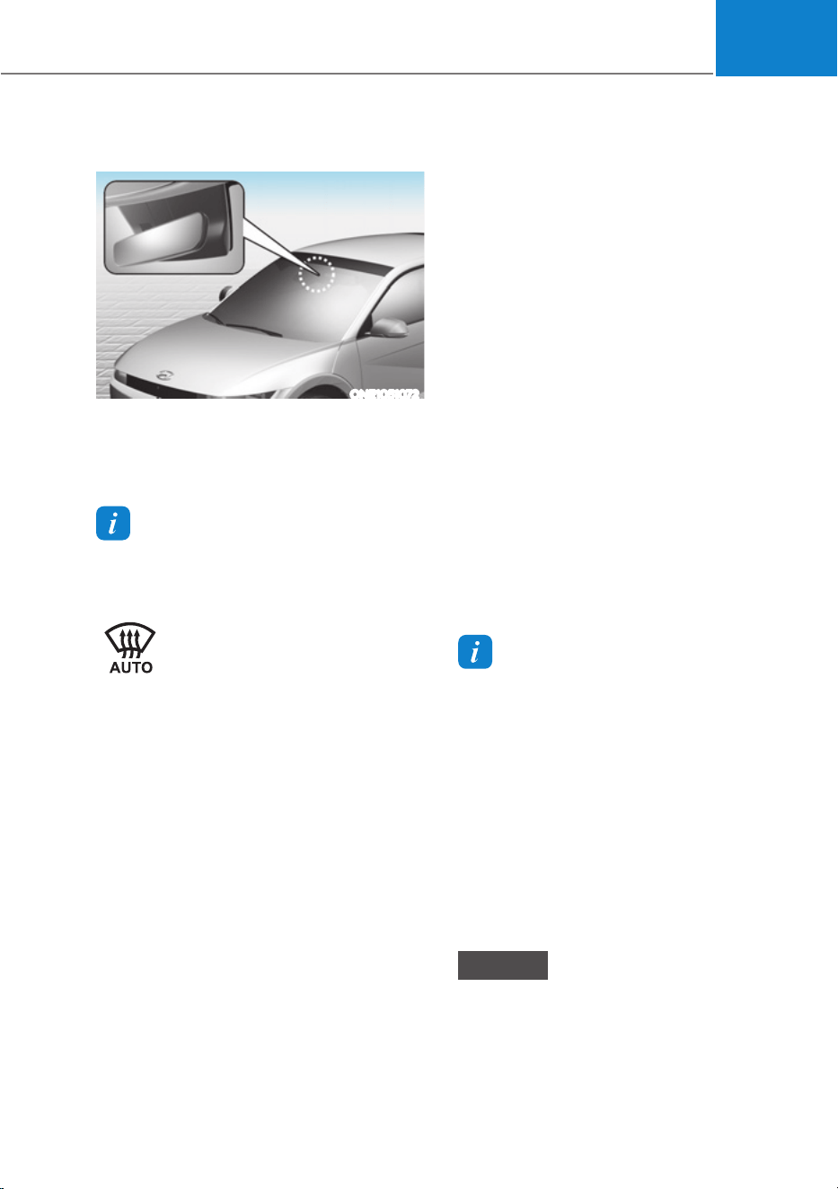
05
5-117
Auto Defogging System
ONE1051072
Auto defogging helps reduce the
possibility of fogging up the inside of the
windshield by automatically sensing the
moisture on inside the windshield.
Information
The auto defogging system may not
operate normally, when the outside
temperature is below 14 °F (-10 °C).
When the Auto Defogging
System operates, the indicator
will illuminate.
If a high amount of humidity is detected
in the vehicle, the Auto Defogging
System will be enabled. The following
steps will be performed automatically:
Step 1) Air conditioning will turn ON.
Step 2) Air intake control will change to
Fresh mode.
Step 3) Mode will change to defrost to
direct airflow to the windshield.
Step 4) Fan speed will be set to MAX.
If the air conditioning is off or
recirculation mode is manually selected
while Auto Defogging System is ON, the
Auto Defogging System will be canceled.
Turning the Auto Defogging System
ON or OFF
Climate control system
Touch the front windshield defroster
icon for 3 seconds when the Start/Stop
button is in the ON position. When the
Auto Defogging System is turned off, the
ADS OFF symbol will blink 3 times and
ADS OFF will be displayed on the climate
control information screen.
When the Auto Defogging System is
turned on, the ADS OFF symbol will blink
6 times without a signal.
Infotainment system
Auto Defogging System can be turned
RQDQGRIIE\VHOHFWLQJœ6HWXSƟ
9HKLFOH6HWWLQJVƟ&OLPDWHƟ'HIRJ
'HIURVW2SWLRQVƟ$XWR'HIRJŔIURPWKH
infotainment system screen.
For detailed information, refer to the
separately supplied infotainment
system manual.
Information
ś :KHQWKHDLUFRQGLWLRQLQJLVWXUQHG
on by Auto Defogging System, if you
try to turn off the air conditioning, the
indicator will blink 3 times and the air
conditioning will not be turned off.
ś To maintain the effectiveness and
efficiency of the Auto Defogging
System, do not select Recirculation
mode while the system is operating.
ś :KHQ$XWR'HIRJJLQJ6\VWHPLV
operating, fan speed adjustment,
temperature adjustment, and air intake
control selection are all disabled.
NOTICE
Do not remove the sensor cover located
on the upper end of the windshield
glass.
Damage to system parts could occur
and may not be covered by your vehicle
warranty.

Convenience Features
5-118
Auto Dehumidify (if equipped)
To increase cabin air quality and reduce
windshield misting, recirculation mode
switches off automatically after about
5 minutes, depending on the outside
temperature, and the air intake will
change to fresh mode.
Turning Auto Dehumidify ON or OFF
Climate control system
To turn the Auto Dehumidify feature on
or off, select Face level (
) mode and
touch the air intake control icon at least
five times within three seconds. When
Auto Dehumidify is turned on, the air
intake control button indicator will blink
6 times. When turned off, the indicator
will blink 3 times.
Infotainment system
Auto Dehumidify can be turned on and
RIIE\VHOHFWLQJœ6HWXSƟ9HKLFOH6HWWLQJV
Ɵ&OLPDWHƟ$XWRPDWLF9HQWLODWLRQƟ
Auto Dehumidify’ from the infotainment
system screen.
Information
,IWKHEDWWHU\9LVGLVFKDUJHGRU
disconnected, Auto dehumidify settings
will be reset. Readjust the settings to
turning Auto dehumidify option ON or
OFF.
For detailed information, refer to the
separately supplied infotainment system
manual.
Recirculating Air When Washer
Fluid Is Used
Recirculation mode automatically
activates to reduce any objectionable
scent of the washer fluid from entering
the cabin when the windshield washer is
used.
Turning Activate upon Washer Fluid
Use ON or OFF
Activate upon Washer Fluid Use can be
WXUQHGRQDQGRIIE\VHOHFWLQJœ6HWXSƟ
9HKLFOH6HWWLQJVƟ&OLPDWHƟ5HFLUFXODWH
$LUƟ$FWLYDWHXSRQ:DVKHU)OXLG8VH
(or Interlocking washer fluid)’ from the
infotainment system screen.
For detailed information, refer to the
separately supplied infotainment
system manual.

05
5-119
Auto. Controls That Use Climate
Control Settings (for driver’s
seat)
The temperature of the driver’s seat
warmer, air ventilated seat and heated
steering wheel is automatically
controlled depending on the inside and
outside temperature of the vehicle when
the vehicle is running.
To use these features, it must be
enabled from the Settings menu in the
infotainment system screen. Select:
- 6HWXSƟ9HKLFOH6HWWLQJVƟ6HDWƟ
+HDWHG9HQWLODWHG)HDWXUHVƟ+HDWHG
9HQWLODWHG)HDWXUHVƟ$XWR&RQWUROV
That Use Climate Control Settings
For more details on Auto Comfort
Control, refer to “Seat Warmers” and
“Air ventilation seats” section in chapter
3 and “Heated Steering Wheel” section
in this chapter.
Smart ventilation
The smart ventilation system maintains
pleasant/fresh air condition inside
the passenger compartment by
automatically detecting/controlling
the temperature and humidity, when
you drive the vehicle with the climate
control system in the OFF position.
When the smart ventilation system
starts to operate, the message “SMART
VENTILATION ON” appears for 5
seconds.
ś The smart ventilation system stops
operating, when the BLOWER DOWN
OFF button of the climate control
system is selected.
ś The smart ventilation system stops
operating, when any button of the
climate control system is selected for
operation.
ś The smart ventilation system may not
operate, when the vehicle is driven at
low speed.
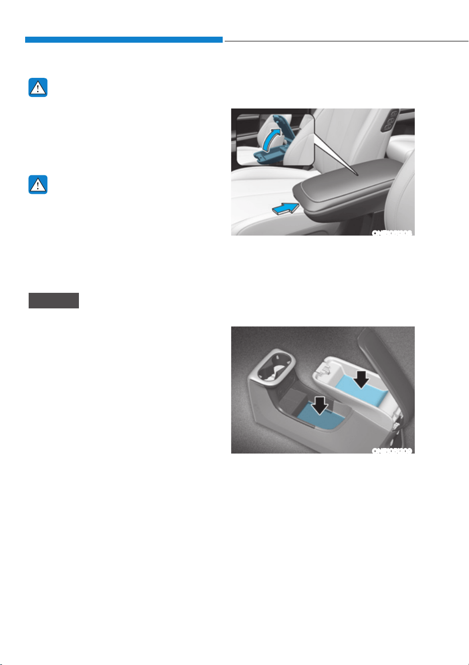
Convenience Features
5-120
WARNING
Never store cigarette lighters, propane
cylinders, or other flammable/explosive
materials in the vehicle. These items
may catch fire and/or explode if the
vehicle is exposed to hot temperatures
for extended periods.
WARNING
ALWAYS keep the storage compartment
covers closed securely while driving.
Items inside your vehicle are moving as
fast as the vehicle. If you have to stop
or turn quickly, or if there is a crash, the
items may fly out of the compartment
and may cause an injury if they strike
the driver or a passenger.
NOTICE
To avoid possible theft, do not leave
valuables in the storage compartments.
Center Console Storage
Console Box
ONE1051208
To open :
Grab and hold the latch on the arm rest
then lift the lid.
ś This space provides objects storing
compartment.
Console Storage
ONE1051209
This space provides object storing
compartment.
6725$*(&203$570(17
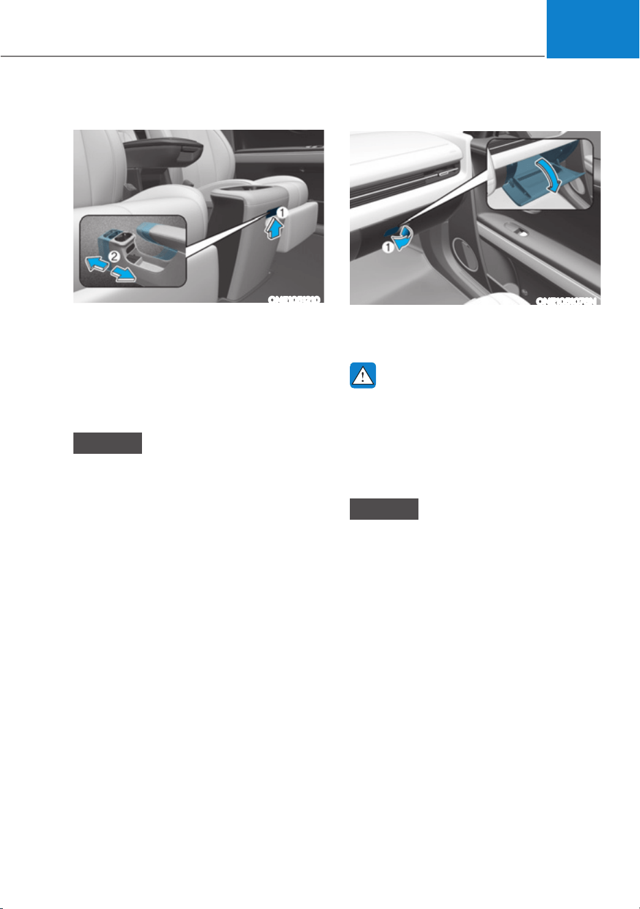
05
5-121
Sliding console (if equipped)
ONE1051210
To slide the console (2) forward/
backward, pressing the handle (1) and
pull or push the console to the desired
position.
Check if the console box makes a ‘click’
sound, after moving the center console
box.
NOTICE
Use of excessive force to the console
box may damage the sliding rail or the
control lever.
Glove Box
ONE1051076N
To open:
Pull the lever (1).
WARNING
ALWAYS close the glove box door after
use.
An open glove box door can cause
serious injury to the passenger in an
accident, even if the passenger is
wearing a seat belt.
NOTICE
Use of excessive force to the glove box
may damage the sliding rail or the lever.
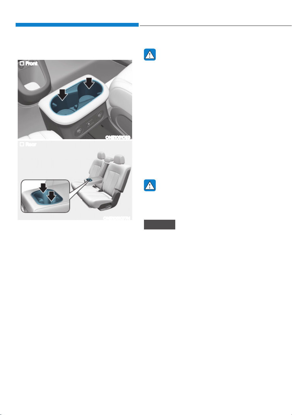
Convenience Features
5-122
INTERIOR FEATURES
Cup Holder
Front
ONE1051083
Rear
ONE1051077N
Cups or small beverages cups may be
placed in the cup holders.
WARNING
ś Avoid abrupt starting and braking
when the cup holder is in use to
prevent spilling your drink. If hot
liquid spills, you could be burned.
Such a burn to the driver could cause
loss of vehicle control resulting in an
accident.
ś Do not place uncovered or unsecured
cups, bottles, cans, etc., in the cup
holder containing hot liquid while
the vehicle is in motion. Injuries may
result in the event of a sudden stop
or collision.
ś Only use soft cups in the cup holders.
Hard objects can injure you in an
accident.
WARNING
Keep cans or bottles out of direct sun
light and do not put them in a hot
vehicle. It may explode.
NOTICE
ś Keep your drinks sealed while
driving to prevent spilling your drink.
If liquid spills, it may get into the
vehicle’s electrical/electronic system
and damage electrical/electronic
parts.
ś When cleaning spilled liquids do not
use hot air to blow out or dry the cup
holder. This may damage the interior.
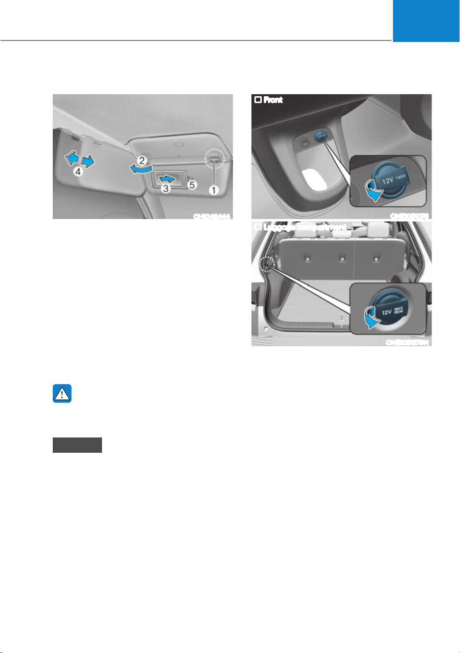
05
5-123
Sunvisor
OHI048444
To use the sunvisor, pull it downward.
To use the sunvisor to block the sun
from the side window, pull it downward,
release it from the bracket (1) and swing
it to the side (2) towards the window.
To use the vanity mirror, pull down the
sunvisor and slide the mirror cover (3).
Adjust the sunvisor forward or backward
(4) as needed (if equipped). Use the
ticket holder (5) to hold tickets.
Close the vanity mirror cover securely
and return the sunvisor to its original
position after use.
WARNING
For your safety, do not block your view
when using the sunvisor.
NOTICE
ś The tab (5) adjacent to the vanity
mirror on the sunvisor can be used
for toll road tickets or self parking
tickets. Use caution when inserting
tickets into the ticket holder to avoid
damage. Refrain from putting several
tickets in the ticket holder as this
could also damage the retaining tab.
ś Always have the switch in the off
position when the vanity mirror
lamp is not in use. If the sunvisor is
closed without the lamp off, it may
discharge the battery or damage the
sunvisor.
Power Outlet
Front
ONE1051078
Luggage compartment
ONE1051279N
The power outlet is designed to provide
power for mobile telephones or other
devices designed to operate with vehicle
electrical systems. The devices should
draw less than 180 watts with the vehicle
running.
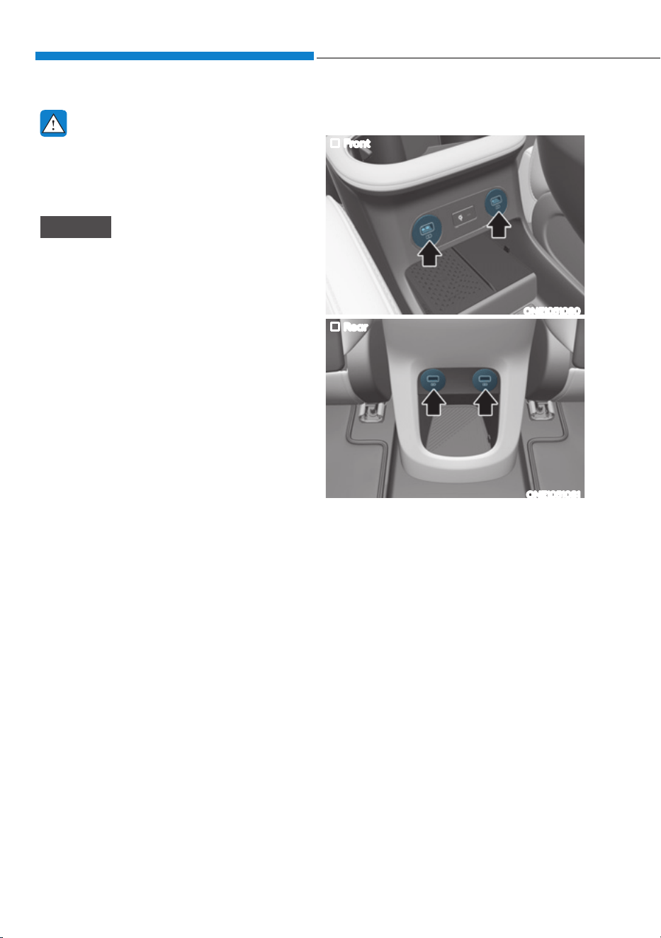
Convenience Features
5-124
WARNING
Avoid electrical shocks. Do not place
your fingers or foreign objects (pin, etc.)
into a power outlet or touch the power
outlet with a wet hand.
NOTICE
To prevent damage to the power
outlets:
ś Use the power outlet only when the
vehicle is running and remove the
accessory plug after use. Using the
accessory plug for prolonged periods
of time with the vehicle off could
cause the battery to discharge.
ś Only use 12 volts electric accessories
which are less than 180 watts in
electric capacity.
ś Adjust the air-conditioner or heater
to the lowest operating level when
using the power outlet.
ś Close the cover when not in use.
ś Some electronic devices can
cause electronic interference
when plugged into a vehicle’s
power outlet. These devices may
cause excessive audio static and
malfunctions in other electronic
systems or devices used in your
vehicle.
ś Push the plug in as far as it will go. If
good contact is not made, the plug
may overheat and the fuse may open.
ś Plug in battery equipped electrical/
electronic devices with reverse
current protection. The current
from the battery may flow into the
vehicle’s electrical/electronic system
and cause system malfunction.
USB Charger (if equipped)
Front
ONE1051080
Rear
ONE1051081
The USB charger is designed to recharge
batteries of small size electrical devices
using a USB cable.
The electrical devices can be recharged
when the Start/Stop button is in the ON
or START position.
The battery charging state may be
monitored on the electrical device.
Disconnect the USB cable from the USB
port after use.
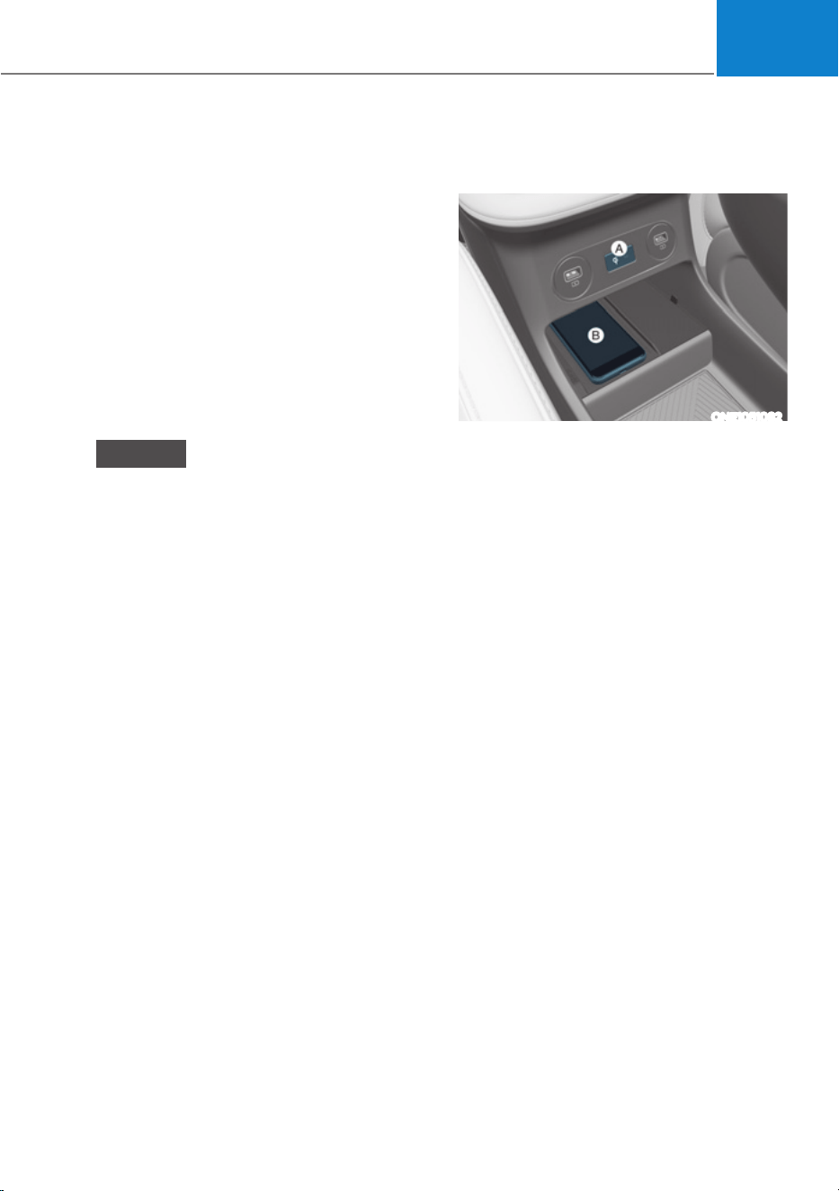
05
5-125
ś A smart phone or a tablet PC may
get warmer during the re-charging
process. It does not indicate any
malfunction with the charging system.
ś A smart phone or a tablet PC, which
adopts a different re-charging
method, may not be properly re-
charged. In this case, use an exclusive
charger of your device.
ś The charging terminal is only to
recharge a device. Do not use the
charging terminal either to turn ON
an audio or to play media In the
infotainment system.
NOTICE
ś Use the USB charger when the
vehicle is running. Using the USB
charger for prolonged periods of
time with the vehicle off could cause
the battery to discharge.
ś To prevent damage to the USB
charger:
- Do not insert foreign objects or
spill liquid into the outlet. The
USB charging terminal may be
damaged.
- Do not use devices with current
consumption exceeding 2,100 mA
(2.1 A).
Wireless Smart Phone Charging
System (if equipped)
ONE1051082
[A] : Indicator light, [B] : Charging pad
On certain models, the vehicle comes
equipped with a wireless smart phone
charger.
The system is available when all doors
are closed, and when the Start/Stop
button is in the ON or START position.

Convenience Features
5-126
Charging smart phone
The wireless smart phone charging
system charges only the Qi-enabled
smart phones (
). Read the label on
the smart phone accessory cover or
visit your smart phone manufacturer’s
website to check whether your smart
phone supports the Qi technology.
The wireless charging process starts
when you put a Qi-enabled smart phone
on the wireless charging unit.
1. Remove other items, including the
smart key, from the wireless charging
unit. If not, the wireless charging
process may be interrupted. Place
the smart phone on the center of the
charging pad.
2. The indicator light is orange when the
smart phone is charging. The indicator
light will turn blue when phone
charging is complete.
3. You can turn ON or OFF the wireless
charging function from the Settings
menu in the infotainment system
screen. Select:
- 6HWXSƟ9HKLFOHƟ&RQYHQLHQFHƟ
Wireless Charging
For detailed information, refer to the
separately supplied infotainment
system manual.
If your smart phone is not charging:
- Slightly change the position of the
smart phone on the charging pad.
- Make sure the indicator light is
orange.
The indicator light will blink orange for 10
seconds if there is a malfunction in the
wireless charging system.
In this case, temporarily stop the
charging process, and re-attempt to
charge your smart phone again.
The system warns you with a message on
the LCD display if the smart phone is still
on the wireless charging unit after the
vehicle is turned OFF and the front door
is opened.
For some manufacturer’s smart phones,
the system may not warn you even
though the smart phone is left on the
wireless charging unit. This is due to the
particular characteristic of the smart
phone and not a malfunction of the
wireless charging.
NOTICE
ś The wireless smart phone charging
system may not support certain
smart phones, which are not verified
for the Qi specification (
).
ś When placing your smart phone on
the charging pad, position the phone
in the middle of the mat for optimal
charging performance. If your smart
phone is off to the side, the charging
rate may be less and in some cases
the smart phone may experience
higher heat conduction.
ś In some cases, the wireless charging
may stop temporarily when the
smart key is used, either when
starting the vehicle or locking/
unlocking the doors, etc.

05
5-127
ś When charging certain smart
phones, the charging indicator may
not change to blue when the smart
phone is fully charged.
ś The wireless charging process may
temporarily stop, when temperature
abnormally increases inside the
wireless smart phone charging
system. The wireless charging
process restarts, when temperature
falls to a certain level.
ś The wireless charging process may
temporarily stop when there is
any metallic item, such as a coin,
between the wireless smart phone
charging system and smart phone.
ś When charging some smart phones
with a self-protection feature,
the wireless charging speed may
decrease and the wireless charging
may stop.
ś If the smart phone has a thick cover,
the wireless charging may not be
possible.
ś If the smart phone is not completely
contacting the charging pad,
wireless charging may not operate
properly.
ś Some magnetic items like credit
cards, phone cards or rail tickets may
be damaged if left with the smart
phone during the charging process.
ś When any smart phone without
a wireless charging function or a
metallic object is placed on the
charging pad, a small noise may
sound. This small sound is due to the
vehicle discerning compatibility of
the object placed on the charging
pad. It does not affect your vehicle or
the smart phone in any way.
Information
If the Start/Stop button is in the OFF
position, the charging also stops.
Information
7KLVGHYLFHFRPSOLHVZLWK3DUWRIWKH
FCC rules.
Operation is subject to the following three
conditions:
1. This device may not cause harmful
interference.
2. This device must accept any
interference received, including
interference that may cause undesired
operation.
3. Changes or modifications not expressly
approved by the party responsible
for compliance could void the user’s
authority to operate the device
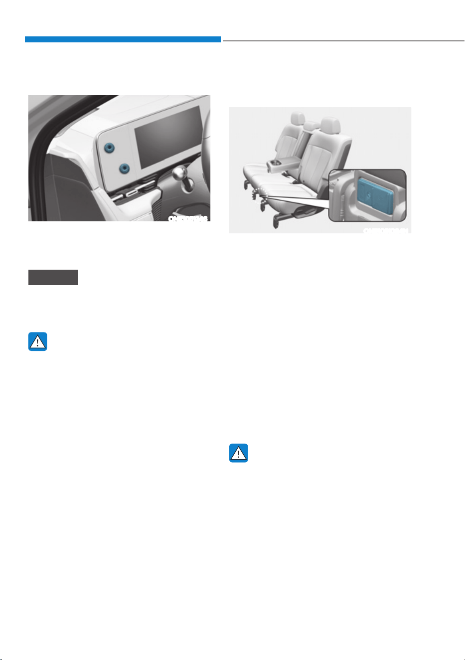
Convenience Features
5-128
Cluster Fascia Side Panel
ONE1051246
The cluster fascia side panel is a pad to
attach light items such as parking tickets,
receipts, etc., using its magnetic surface.
NOTICE
Do not attach heavy items such as
cellular phones. Dropping while driving,
the items can be damaged.
WARNING
Do not attach the cellular phones and
heavy or sharp items to the cluster
fascia side panel for safety reason.
This could result in loss of control, and
an accident causing death, serious
injury, or property damage.
Vehicle to Load (V2L) (if
equipped)
ONE1051084N
V2L(Vehicle to Load) is installed at the
central rear seat. V2L is a convenient
feature which provides enough
electricity to use diverse household
electrical appliances in the vehicle.
V2L is installed at the central rear seat
bottom.
For more details, refer to “Vehicle to
load(V2L)” section in chapter 1.
Clock
The clock can be set from the
infotainment system.
For detailed information, refer to the
separately supplied infotainment
system manual.
WARNING
Do not attempt to adjust the clock
while driving. Doing so may result in
distracted driving which may lead to
an accident involving personal injury or
death.
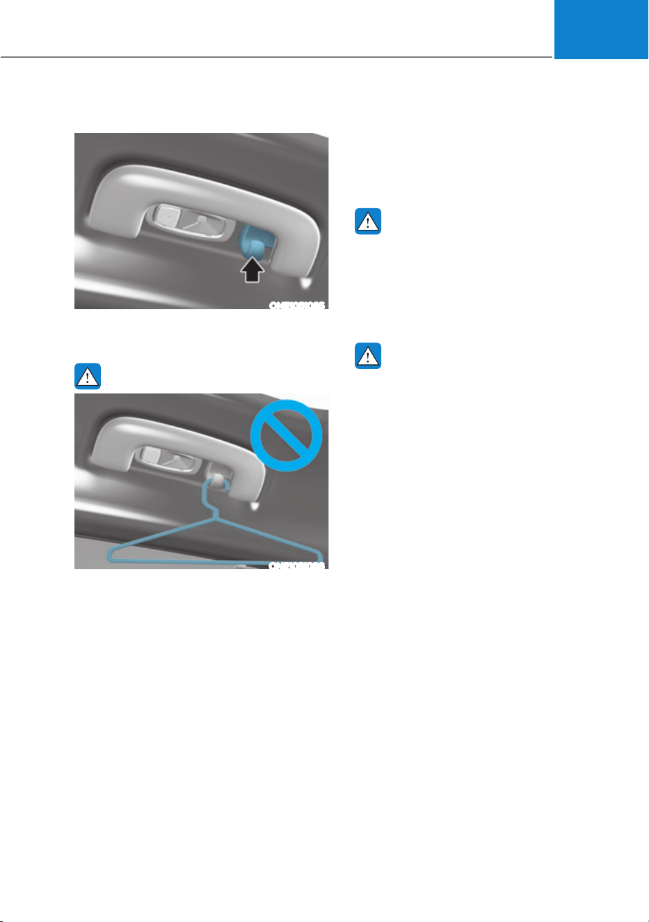
05
5-129
Coat Hook
ONE1051085
These hooks are not designed to hold
large or heavy items.
WARNING
ONE1051086
Do not hang other objects such
as hangers or hard objects except
clothes. Also, do not put heavy, sharp
or breakable objects in the clothes
pockets. In an accident or when the
curtain air bag is inflated, it may cause
vehicle damage or personal injury.
Floor Mat Anchor(s)
ALWAYS use the Floor Mat Anchors to
attach the front floor mats to the vehicle.
The anchors on the front floor carpet
keep the floor mats from sliding forward.
WARNING
Do not overlay additional mats or liners
over the floor mats. If using All Weather
mats, remove the carpeted floor mats
before installing them. Only use floor
mats designed to connect to the
anchors.
WARNING
The following must be observed when
installing ANY floor mat to the vehicle.
ś Ensure to remove a protective
film attached on the carpet
before attaching a floor mat on
the front floor carpet. Otherwise,
the floor mat may move freely on
the protective film and it could
result in unintentional braking or
accelerating.
ś Ensure that the floor mats are
securely attached to the vehicle’s
floor mat anchor(s) before driving
the vehicle.
ś Do not use ANY floor mat that cannot
be firmly attached to the vehicle’s
floor mat anchors.
ś Do not stack floor mats on top of one
another (for example, all-weather
rubber mat on top of a carpeted floor
mat). Only a single floor mat should
be installed in each position.
IMPORTANT Your vehicle was
manufactured with driver’s side
floor mat anchors that are designed
to securely hold the floor mat in
place. To avoid any interference with
pedal operation, HYUNDAI Vehicle
recommends that the HYUNDAI floor
mat designed for use in your vehicle be
installed.
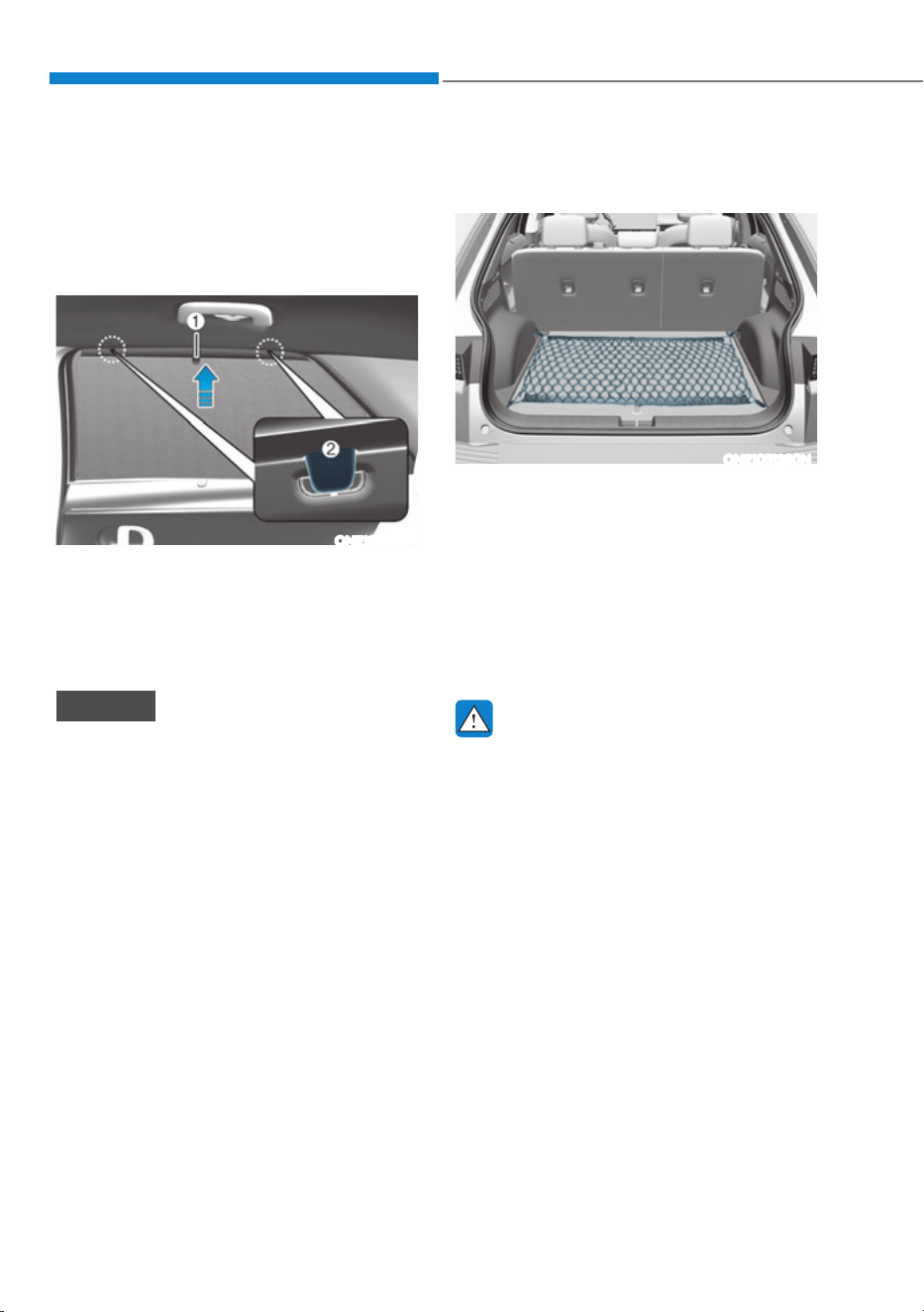
Convenience Features
5-130
Rear Side Window Sunshades (if
equipped)
Use the rear side window sunshade to
block external light coming through the
rear window glass.
ONE1051087
1. Lift the sunshade by the handle (1).
2. Hang the sunshade on both sides of
the hook (2). If the sunshade is hung
on one side of the hook, the sunshade
may be wrinkled.
NOTICE
ś Do not hang any other object except
the rear side window sunshade on
the hooks.
ś If you pull the rear side window
sunshade or apply force to return
the sunshade to its original position
after use, you may find the sunshade
wrinkled or out of shape. To lower
the sunshade, be sure to put the
handle downward and slowly return
the sunshade to its original position.
ś Sunshades may not work properly if
foreign objects (coins, toys, cookies,
etc.) are stuck in the door. Be careful
that the foreign objects do not get
into the door.
Luggage Net Holder (if
equipped)
ONE1051280N
To keep items from shifting in the
luggage compartment, you can use the 4
holders located in the luggage board to
attach the luggage net.
Make sure the luggage net is securely
attached to the holders in the luggage
board.
If necessary, contact your authorized
HYUNDAI dealer to obtain a luggage net.
WARNING
Avoid eye injury. DO NOT overstretch
the luggage net. ALWAYS keep your
face and body out of the luggage net’s
recoil path. DO NOT use the luggage net
when the strap has visible signs of wear
or damage.
Use the luggage net to keep only light
items from shifting in the luggage
compartment.
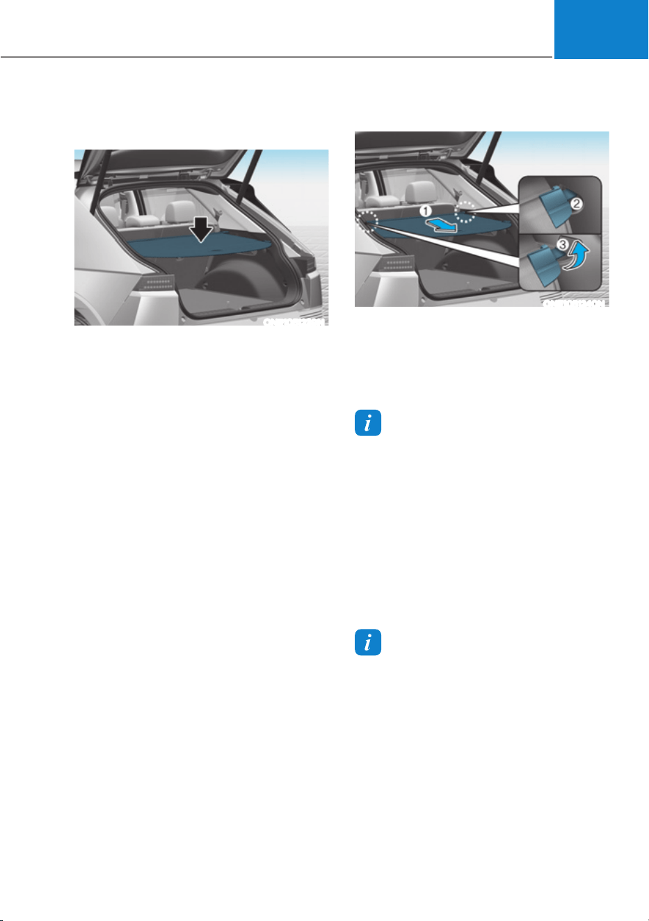
05
5-131
Cargo Security Screen (if
equipped)
ONE1051239N
Use the cargo security screen to cover
items stored in the cargo area.
Using the cargo security screen
ONE1051240N
1. Pull the cargo security screen towards
the rear of the vehicle by the handle
(1).
2. Insert the guide pin (2) into the guide
(3).
Information
3XOORXWWKHFDUJRVHFXULW\VFUHHQZLWKWKH
handle in the center to prevent the guide
pin from falling out of the guide.
:KHQWKHFDUJRVHFXULW\VFUHHQLVQRWLQ
use:
1. Pull the cargo security screen
rearward and down to release it from
the guides.
2. The cargo security screen will
automatically slide back in.
Information
The cargo security screen may not
automatically slide back in if the cargo
VHFXULW\VFUHHQLVQRWIXOO\SXOOHGRXW3XOO
the cargo screen out all the way and then
slowly allow the screen to retract back in.
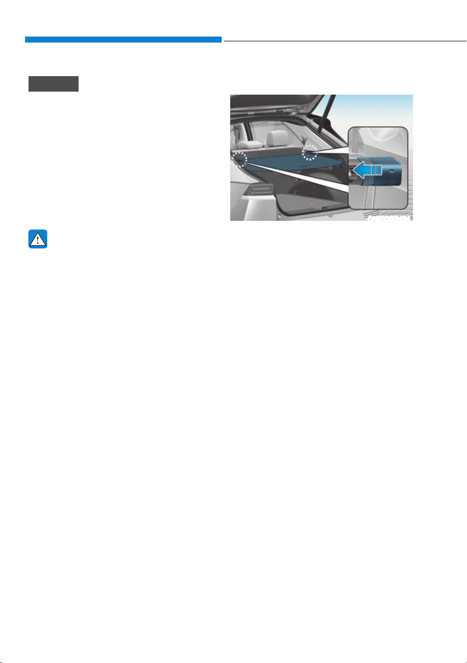
Convenience Features
5-132
NOTICE
ś Since the cargo security screen may
be damaged or malformed, do not
put luggage on it when it is used.
ś The cargo security screen and rear
seat may be damaged when the
rear seat slides forward/rearward or
when the rear seatback is reclined.
ś Note that if you release the handle
while pulling the luggage screen
handle all the way, the screen may
wind up quickly and be damaged.
WARNING
ś Do not place objects on the cargo
security screen. Such objects may be
thrown about inside the vehicle and
possibly injure vehicle occupants
during an accident or when braking.
ś Never allow anyone to ride in the
luggage compartment. It is designed
for luggage only.
ś Maintain the balance of the vehicle
and locate the weight as forward as
possible.
Removing the cargo security screen
ONE1051241N
1. Push one side of the cargo screen
inward to compress the spring and
release the screen from the vehicle.
2. While the spring is compressed, pull
out the cargo security screen.
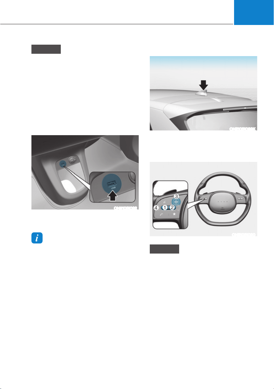
05
5-133
NOTICE
ś If you install an aftermarket HID
head lamp, your vehicle’s audio and
electronic devices may not function
properly.
ś Prevent chemicals such as perfume,
cosmetic oil, sun cream, hand
cleaner, and air freshener from
contacting the interior parts
because they may cause damage or
discoloration.
USB Port
ONE1051092
You can use an USB cable to connect
audio devices to the vehicle USB port.
Information
:KHQXVLQJDSRUWDEOHDXGLRGHYLFH
connected to the power outlet, noise may
occur during playback. If this happens,
use the portable audio device’s power
source.
Antenna
ONE1051089K
The shark fin antenna will receive AM,
FM broadcast signals and transmit data.
Steering Wheel Remote Controls
ONE1051090
NOTICE
Do not operate multiple audio remote
control buttons simultaneously.
,1)27$,10(176<67(0
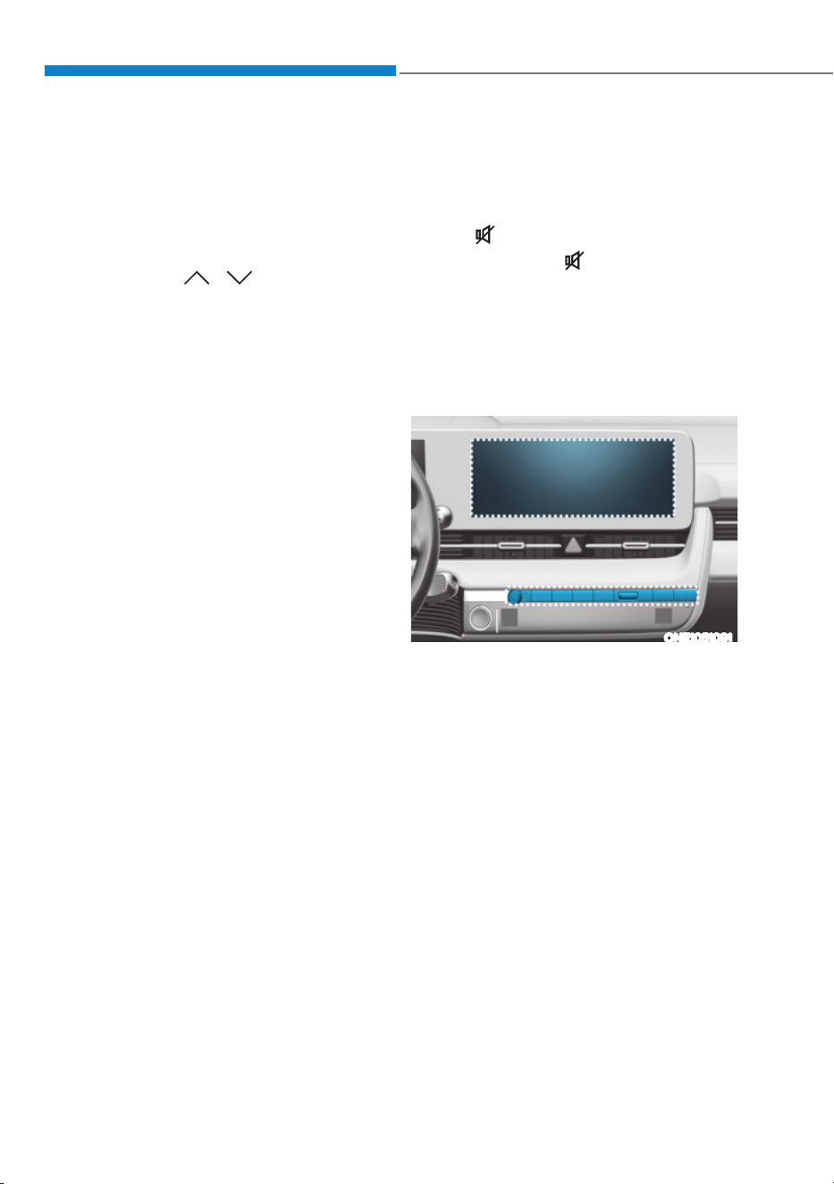
Convenience Features
5-134
VOLUME (VOL + / VOL -) (1)
ś Rotate the VOLUME scroll up to
increase volume.
ś Rotate the VOLUME scroll down to
decrease volume.
SEEK/PRESET ( / ) (2)
If the SEEK/PRESET switch is pressed up
or down and held for 0.8 second or more,
it will function in the following modes:
ś
RADIO mode
It will function as the AUTO SEEK
select button. It will SEEK until you
release the button.
ś
0(',$PRGH
It will function as the FF/RW button.
If the SEEK/PRESET switch is pressed up
or down, it will function in the following
modes:
ś RADIO mode
It will function as the PRESET STATION
UP/DOWN button.
ś
0(',$PRGH
It will function as the TRACK UP/
DOWN button.
MODE (3)
Press the MODE button to toggle
through Radio or AUX modes.
MUTE ( ) (4)
ś Press the MUTE( )button to mute or
activate the sound.
For detailed information, refer to the
separately supplied infotainment
system manual.
Infotainment System
ONE1051091
For detailed information, refer to the
separately supplied infotainment
system manual.
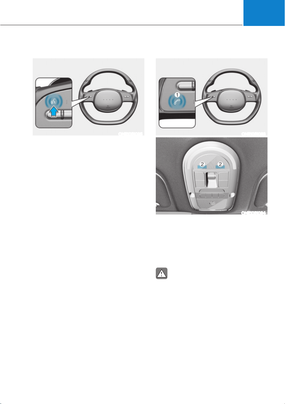
05
5-135
Voice Recognition
ONE1051095
For detailed information, refer to the
separately supplied infotainment
system manual.
Bluetooth® Wireless Technology
ONE1051093
ONE1051094
(1) Call / Answer / Call end button
(2) Microphone
For detailed information, refer to the
separately supplied infotainment
system manual.
CAUTION
To avoid driver distractions, do not
excessively operate the device while
driving the vehicle which may lead to
an accident.

6
6. Driving Your Vehicle
Before Driving ................................................................................................... 6-3
Before Entering the Vehicle .........................................................................................6-3
Before Starting .............................................................................................................6-3
Start/Stop Button ..............................................................................................6-4
Start/Stop Button Positions .........................................................................................6-5
Starting the Vehicle ..................................................................................................... 6-6
Turning Off the Vehicle ................................................................................................ 6-7
Remote Start ................................................................................................................ 6-8
Transmission (Reduction Gear) ........................................................................6-9
Rotary Shifter Operation ............................................................................................. 6-9
LCD Display Messages (Cluster) ................................................................................ 6-13
Good Driving Practices .............................................................................................. 6-15
Regenerative Braking System .........................................................................6-16
One Pedal Driving........................................................................................................6-17
i-Pedal ......................................................................................................................... 6-18
Smart Recuperation System ...........................................................................6-19
Smart Recuperation System Setting ......................................................................... 6-19
To Activate Smart Recuperation System .................................................................. 6-19
Ready to Operate ...................................................................................................... 6-20
How to Operate .......................................................................................................... 6-21
Smart Recuperation System Will Be Temporarily Cancelled When: ....................... 6-21
To Resume Smart Recuperation System .................................................................. 6-21
Vehicle-to-Vehicle Distance Recognition Sensor (Front Radar) .............................6-22
System Malfunction ...................................................................................................6-23
Limitations of the System ..........................................................................................6-23
Braking System ............................................................................................... 6-26
Power-Assist Brakes ...................................................................................................6-26
Disc Brakes Wear Indicator........................................................................................ 6-27
Electronic Parking Brake (EPB) .................................................................................. 6-27
Auto Hold ....................................................................................................................6-32
Anti-Lock Brake System (ABS) ...................................................................................6-35
Electronic Stability Control (ESC) .............................................................................6-37
Vehicle Stability Management (VSM) ...................................................................... 6-40
Hill-Start Assist Control (HAC) ................................................................................... 6-41
Good Braking Practices ............................................................................................ 6-42

6
All Wheel Drive (AWD) ...................................................................................6-43
Emergency Precautions ............................................................................................ 6-45
Drive Mode Integrated Control System (2WD) ............................................ 6-47
Drive Mode .................................................................................................................6-47
Drive Mode Integrated Control System (AWD) .............................................6-49
Drive Mode ................................................................................................................ 6-49
Drive Modes Characteristic ....................................................................................... 6-51
Active Air Flap ................................................................................................. 6-52
Malfunction ................................................................................................................6-52
Special Driving Conditions ............................................................................. 6-53
Hazardous Driving Conditions ..................................................................................6-53
Rocking the Vehicle ...................................................................................................6-53
Smooth Cornering ..................................................................................................... 6-54
Driving at Night ......................................................................................................... 6-54
Driving in the Rain ..................................................................................................... 6-54
Driving in Flooded Areas ............................................................................................6-55
Highway Driving .........................................................................................................6-55
Reducing the Risk of a Rollover ............................................................................... 6-56
Winter Driving ................................................................................................. 6-57
Snow or Icy Conditions ..............................................................................................6-57
Winter Precautions .................................................................................................... 6-60
Vehicle Load Limit ...........................................................................................6-61
The Loading Information Label ................................................................................ 6-62
Trailer Towing ..................................................................................................6-68
If You Decide to Pull a Trailer .................................................................................... 6-68
Trailer Towing Equipment ...........................................................................................6-71
Driving with a Trailer .................................................................................................. 6-72
Maintenance when Towing a Trailer ......................................................................... 6-75
Vehicle Weight ................................................................................................ 6-76
Overloading ................................................................................................................6-76

06
6-3
WARNING
CALIFORNIA PROPOSITION 65
WARNING
Engine exhaust and a wide variety of
automobile components including
components found in the interior
furnishings in a vehicle, contain or
emit harmful chemicals known to the
State of California to cause cancer and
birth defects and reproductive harm.
In addition, certain fluids contained
in vehicles and certain products of
components contain or emit chemicals
known to the State of California to
cause cancer and birth defects or other
reproductive harm.
Before Entering the Vehicle
ś Be sure all windows, outside mirror(s),
and outside lights are clean and
unobstructed.
ś Remove frost, snow, or ice.
ś Visually check the tires for uneven
wear and damage.
ś Check under the vehicle for any sign
of leaks.
ś Be sure there are no obstacles behind
you if you intend to back up.
Before Starting
ś Make sure the hood, the liftgate, and
the doors are securely closed and
locked.
ś Adjust the position of the seat and
steering wheel.
ś Adjust the inside and outside rearview
mirrors.
ś Verify all the lights work.
ś Fasten your seat belt. Check that all
passengers have fastened their seat
belts.
ś Check the gauges and indicators
in the instrument panel and the
messages on the instrument display
when the vehicle is in the ON position.
ś Check that any items you are carrying
are stored properly or fastened down
securely.
WARNING
To reduce the risk of SERIOUS INJURY or
DEATH, take the following precautions:
ś ALWAYS wear your seat belt. All
passengers must be properly belted
whenever the vehicle is moving.
For more information, refer to “Seat
Belts” section in chapter 3.
ś Always drive defensively. Assume
other drivers or pedestrians may be
careless and make mistakes.
ś Stay focused on the task of driving.
Driver distraction can cause
accidents.
ś Leave plenty of space between you
and the vehicle in front of you.
WARNING
NEVER drink or take drugs and drive.
Drinking or taking drugs and driving
is dangerous and may result in an
accident and SERIOUS INJURY or
DEATH.
Drunk driving is the number one
contributor to the highway death
toll each year. Even a small amount
of alcohol will affect your reflexes,
perceptions and judgment. Just
one drink can reduce your ability to
respond to changing conditions and
emergencies and your reaction time
gets worse with each additional drink.
Driving while under the influence
of drugs is as dangerous or more
dangerous than driving under the
influence of alcohol.
You are much more likely to have a
serious accident if you drink or take
drugs and drive. If you are drinking or
taking drugs, don’t drive. Do not ride
with a driver who has been drinking
or taking drugs. Choose a designated
driver or call a taxi.
BEFORE DRIVING
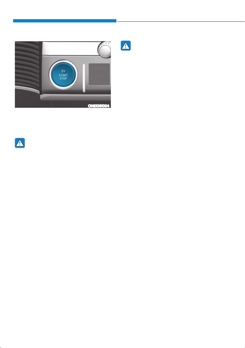
Driving Your Vehicle
6-4
ONE1061004
Whenever the front door is opened, the
Start/Stop button will illuminate and
will go off 30 seconds after the door is
closed.
WARNING
To turn the vehicle off in an emergency:
Press and hold the Start/Stop button
for more than two seconds OR Rapidly
press and release the Start/Stop button
three times (within three seconds).
If the vehicle is still moving, you can
restart the vehicle without depressing
the brake pedal by pressing the Start/
Stop button with the gear in the N
(Neutral) position.
WARNING
ś NEVER press the Start/Stop button
while the vehicle is in motion except
in an emergency. This will result in
the vehicle turning off and loss of
power assist for the steering and
brake systems. This may lead to loss
of directional control and braking
function, which could cause an
accident.
ś Before leaving the driver’s seat,
always make sure the gear is in the
P (Park) position, set the parking
brake, press the Start/Stop button
to the OFF position, and take the
Smart Key with you. Unexpected
vehicle movement may occur if these
precautions are not followed.
ś NEVER reach through the steering
wheel for the Start/Stop button or
any other control while the vehicle
is in motion. The presence of your
hand or arm in this area may cause a
loss of vehicle control resulting in an
accident.
START/STOP BUTTON

06
6-5
Start/Stop Button Positions
Button
Position
Action Notes
OFF
To turn off the vehicle, press the Start/
Stop button with the vehicle shifted to
P (Park).
Note if the Start/Stop button is
pressed with the vehicle shifted to
D (Drive), R (Reverse) or N (Neutral),
the gear will automatically shift to P
(Park).
If the Start/Stop button is pressed
with the gear shifted to N (Neutral),
the Start/Stop button will change to
the ACC position.
The steering wheel locks to protect
the vehicle from theft.
If the steering wheel is not locked
properly when you open the driver’s
door, the warning chime will sound.
ACC
Press the Start/Stop button when the
button is in the OFF position without
depressing the brake pedal.
Some of the electrical accessories are
usable.
The steering wheel unlocks.
śIf you leave the Start/Stop button in
the ACC position for more than one
hour, the battery power will turn off
automatically to prevent the battery
from discharging.
śIf the steering wheel doesn’t unlock
properly, the Start/Stop button
will not work. Press the Start/Stop
button while turning the steering
wheel right and left to release.
ON
Press the Start/Stop button while
it is in the ACC position without
depressing the brake pedal.
The warning lights can be checked
before the vehicle is started.
Do not leave the Start/Stop button
in the ON position when the vehicle
is not running to prevent the battery
from discharging.
START
To start the vehicle, depress the brake
pedal and press the Start/ Stop button
with the gear shifted to the P (Park)
position.
For your safety, start the vehicle
with the gear shifted to the P (Park)
position.
If you press the Start/Stop button
without depressing the brake pedal,
the vehicle does not start and the
Start/Stop button changes as follows:
2))Ɵ$&&Ɵ21Ɵ2))RU$&&
à To prevent vehicle battery discharge, the Start/Stop button changes to the OFF
position when the Start/Stop button is in the ACC or ON position with the gear in
P (Park) for a certain period of time. When the function operates, the tail lamps
will turn off. To use the tail lamps again, turn the headlamp switch located on the
steering column to the OFF and ON position again.
Driving Your Vehicle
6-6
Starting the Vehicle
WARNING
ś Always wear appropriate shoes when
operating your vehicle. Unsuitable
shoes, such as high heels, ski boots,
sandals, flipflops, etc., may interfere
with your ability to use the brake and
accelerator pedals.
ś Do not start the vehicle with the
accelerator pedal depressed.
The vehicle can move which can lead
to an accident.
Information
ś The vehicle will start by pressing the
Start/Stop button, only when the smart
key is in the vehicle.
ś Even if the smart key is in the vehicle,
and when it is far away from the driver,
the vehicle may not start.
ś When the Start/Stop button is in the
ACC or ON position, if any door is
open, the system checks for the smart
key. When the smart key is not in the
vehicle, the “
” indicator will
blink and the warning 'Key not in
vehicle' will come on. When all doors
are closed, the chime will also sound for
about 5 seconds. Keep the smart key in
the vehicle when in the ACC position
or if the vehicle is in the ready (
)
mode.
Starting the vehicle
1. Always carry the smart key with you.
2. Make sure the parking brake is
applied.
3. Make sure the gear is in P (Park).
4. Depress the brake pedal.
5. Press the START/STOP button. If the
vehicle starts, the "
" indicator
will come on.
Information
ś Always start the vehicle with your foot
on the brake pedal. Do not depress the
accelerator while starting the vehicle.
Do not race the motor while warming
it up.
ś If ambient temperature is low, the
“
” indicator may remain
illuminated longer than the normal
amount of time.
NOTICE
To prevent damage to the vehicle:
ś If the (
) indicator turns off
while you are in motion, do not
attempt to shift the gear to the P
(Park) position.
If traffic and road conditions permit,
you may put the gear in N (Neutral)
while the vehicle is still moving and
press the Start/Stop button in an
attempt to restart the vehicle.
ś Do not push or tow your vehicle to
start the vehicle.
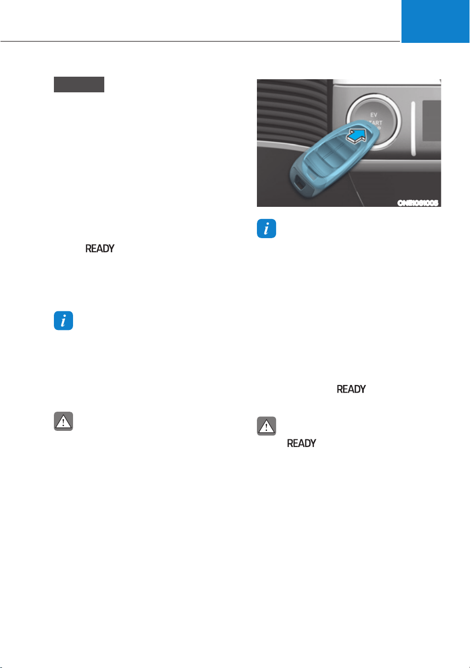
06
6-7
NOTICE
To prevent damage to the vehicle:
Do not press the Start/Stop button for
more than 10 seconds except when the
stop lamp fuse is blown.
When the stop lamp fuse is blown,
you cannot normally start the vehicle.
Replace the fuse with a new one. If you
are not able to replace the fuse, you
can start the vehicle by pressing and
holding the Start/Stop button for 10
seconds with the Start/Stop button in
the ACC position.
Pressing the brake pedal many times
while “
” indicator light is off will
increase the possibility of discharging
the 12V battery.
For your safety always depress the
brake pedal before starting the vehicle.
Information
Virtual Engine Sound System(VESS)
VESS generates virtual engine sound to
make pedestrians to aware. VESS operates
when the vehicle can be driven. When the
vehicle in P(parking) gear status, VESS
doesn't work.
CAUTION
ś Because the vehicle doesn't make
the engine sound, pay attention to
the surrounding environment and
drive carefully.
ś After parking or waiting for a traffic
light, please check around(children,
obstacle, etc.) before departure.
ś When reversing, check directly
behind you before driving.
Pedestrians may not be able to
recognize vehicle sounds.
ONE1061005
Information
If the smart key battery is weak or the
smart key does not work correctly, you
can start the vehicle by pressing the Start/
Stop button with the smart key in the
direction of the picture above.
Turning Off the Vehicle
1. Stop the vehicle and depress the
brake pedal fully.
2. Shift to P (Park).
3. Press the Start/Stop button to the OFF
position and apply the parking brake.
4. Make sure the ‘
’ indicator light
is off in the instrument cluster.
CAUTION
If the " " indicator light on the
instrument cluster is still on, the vehicle
is not turned off and can move when
the gear is in any position except P
(Park).
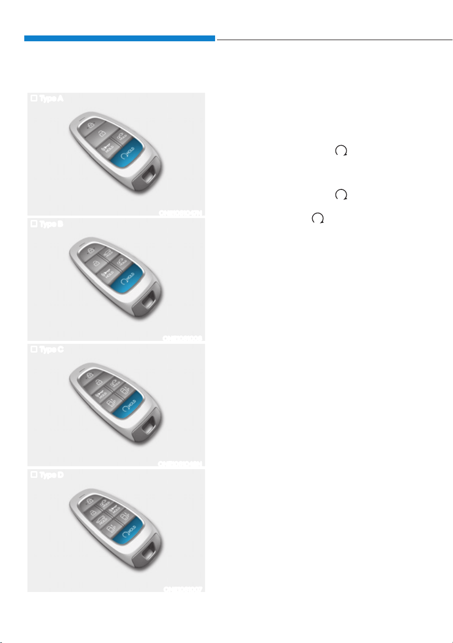
Driving Your Vehicle
6-8
Remote Start
Type A
ONE1061047N
Type B
ONE1061006
Type C
ONE1061048N
Type D
ONE1061007
You can start the vehicle using the
Remote Start button of the smart key.
To start the vehicle remotely:
1. Press the door lock button within 32
feet (10 m) from the vehicle.
2. Press the remote start (
) button for
over 2 seconds within 4 seconds after
locking the doors.
3. To turn off the remote start function,
press the remote start (
) button
once.
ś The remote start (
) button may not
operate if the smart key is not within
32 feet (10 m).
ś The vehicle will not remotely start if
the hood or liftgate is opened.
ś The vehicle must be in P (Park) for the
remote start function to start.
ś The vehicle turns off if you get in the
vehicle without a registered smart key.
ś The vehicle turns off if you do not get
in the vehicle within 10 minutes after
remotely starting the vehicle.
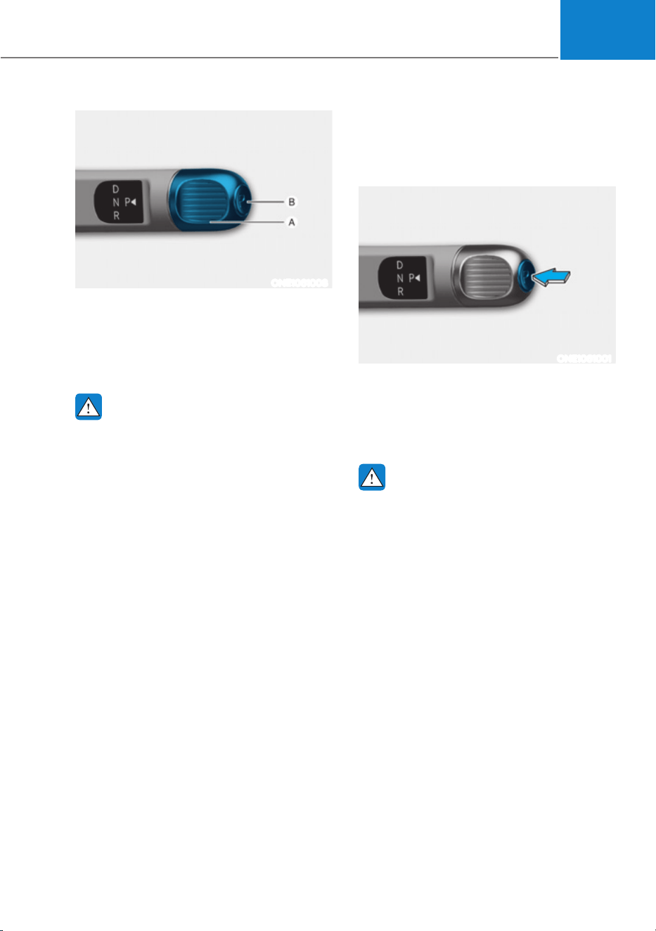
06
6-9
75$160,66,21ǣ5('8&7,21*($5Ǥ
ONE1061008
[A]: Rotary gear shift dial, [B]: P button
Rotary shifter operation
To change the gear, depress the brake
pedal and rotate the rotary gear shift dial.
WARNING
To reduce the risk of serious injury or
death:
ś ALWAYS check the surrounding
areas near your vehicle for people,
especially children, before shifting a
vehicle into D (Drive) or R (Reverse).
ś Before leaving the driver's seat,
always make sure the vehicle is
shifted to the P (Park) position, then
apply the parking brake, then press
the Start/Stop button to the OFF
position. Unexpected and sudden
vehicle movement can occur if these
precautions are not followed.
Rotary shifter/ Rotary gear shift dial
P (Park)
Always come to a complete stop before
shifting into P (Park).
ONE1061001
To shift the gear to P (Park), press the P
button while depressing the brake pedal.
If you turn the vehicle off in R (Reverse),
N (Neutral) or D (Drive), the gear will
automatically shift to P (Park).
WARNING
ś Shifting into P (Park) while the
vehicle is in motion may cause you to
lose control of the vehicle.
ś After the vehicle has stopped, always
make sure the vehicle is in P (Park),
apply the parking brake, and turn the
vehicle off.
ś When parking on an incline, shift
the gear to P (Park) and apply the
parking brake to prevent the vehicle
from rolling downhill.
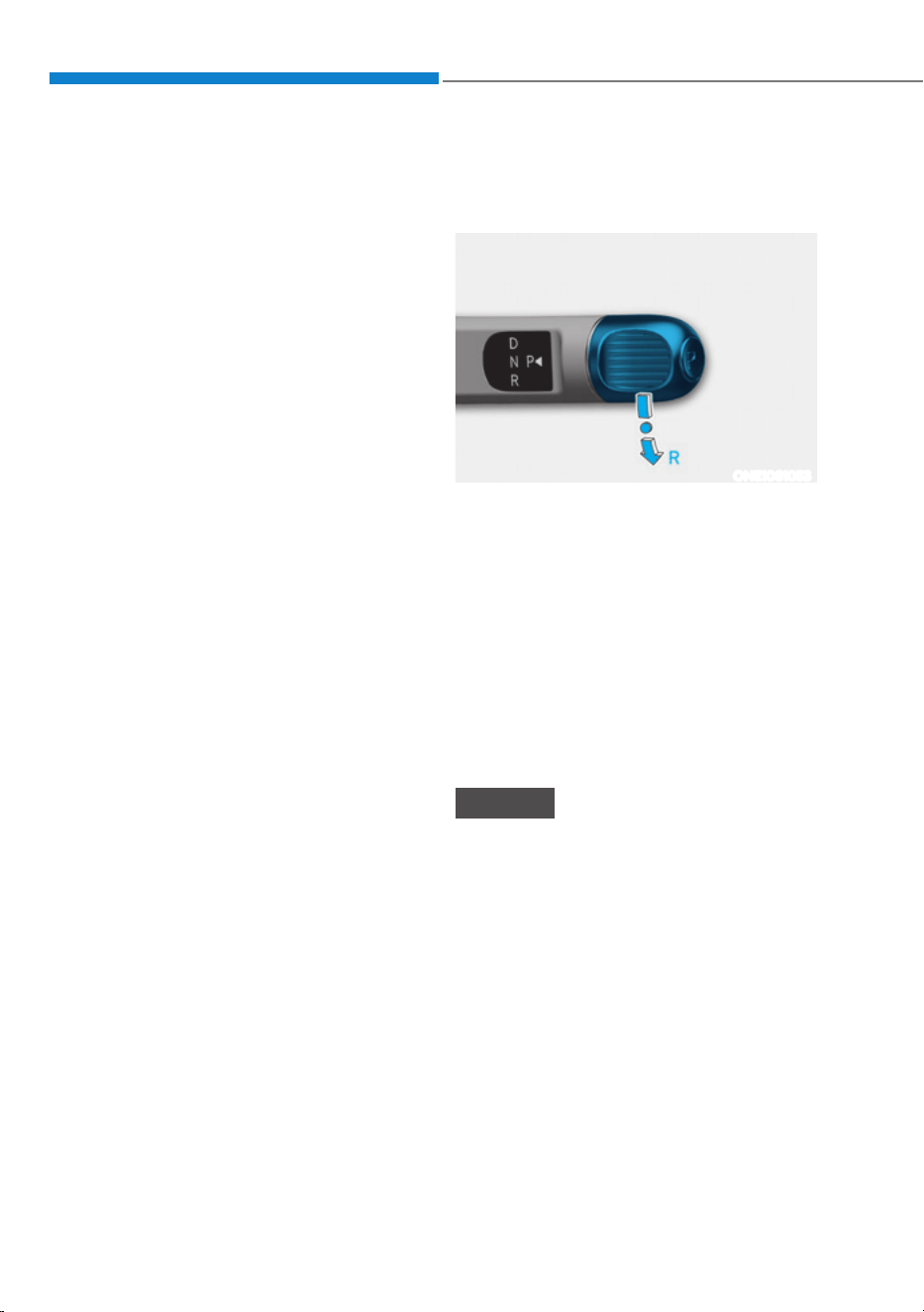
Driving Your Vehicle
6-10
Automatic gear shift to P (Park)
The gear is shifted to P (Park)
automatically for safety reasons under
the following conditions:
- When the vehicle is turned off with
the gear in R (Reverse), D (Drive) or N
(Neutral).
- When the driver’s door is open with
the vehicle running, the gear in R
(Reverse), D (Drive) or N (Neutral), and
the vehicle at a standstill.
- When the driver’s door is open with
the gear in N (Neutral) and the vehicle
is off.
In situations the gear must be in P (Park),
always check if the gear is shifted to P
(Park) by checking the cluster.
R (Reverse)
Use this position to drive the vehicle
rearward.
ONE1061053
To shift the gear to R (Rear), rotate the
rotary gear shift dial to R (Reverse) while
depressing the brake pedal.
When the vehicle is stopped in the
R (Reverse) position, if you open the
driver’s door, the gear will automatically
shift to P (Park).
However, if the vehicle is in motion, the
gear may not automatically shift to P
(Park) to prevent reduction gear damage.
The direction of the rotary gear shift dial
is the same as that of the wheel.
NOTICE
Always come to a complete stop before
shifting into or out of R (Reverse); you
may damage the reduction gear if you
shift into R (Reverse) while the vehicle is
in motion.
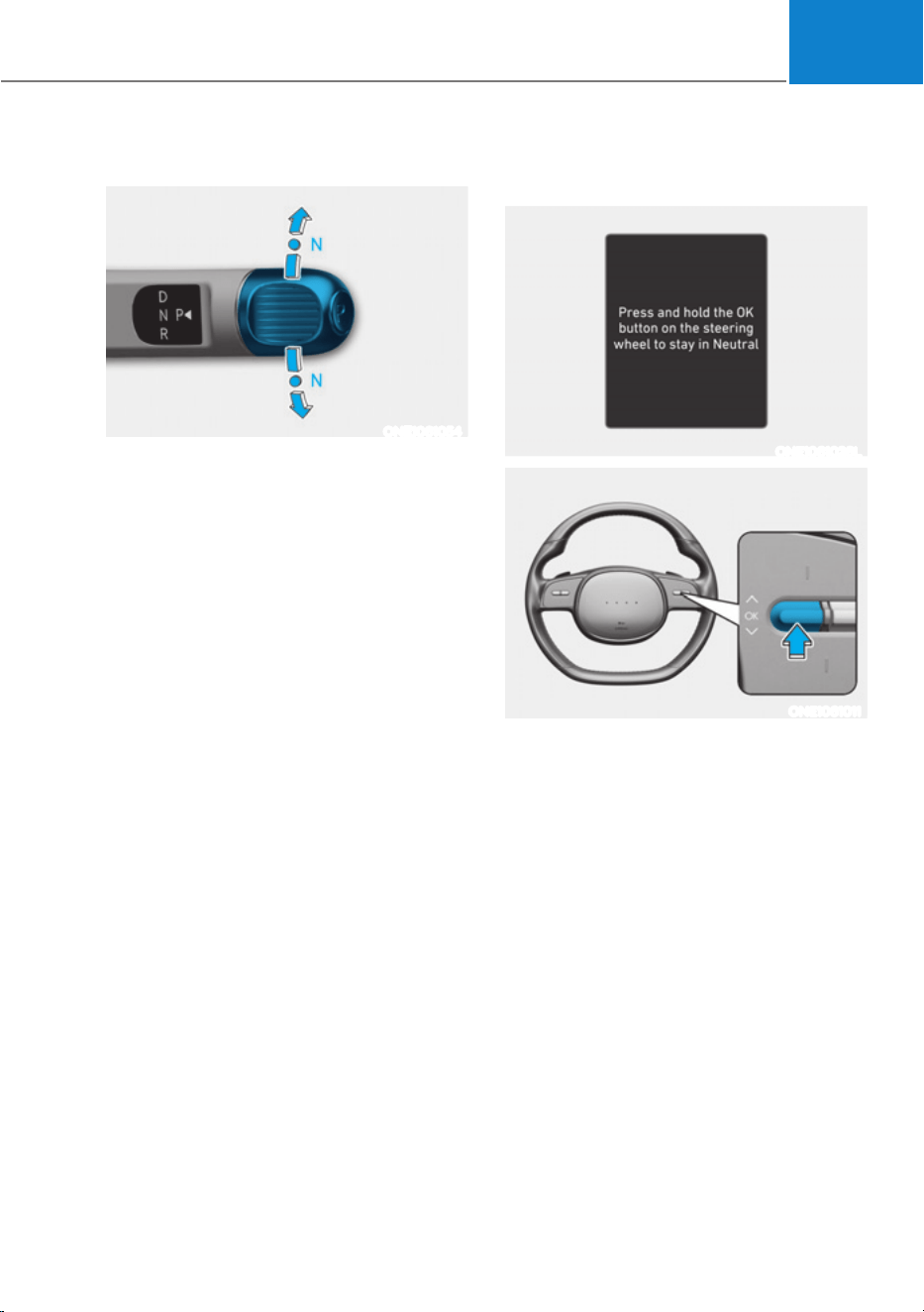
06
6-11
N (Neutral)
ONE1061054
To shift the gear to N (Neutral), rotate the
rotary gear shift dial to N (Neutral) while
depressing the brake pedal.
Always depress the brake pedal when
you are shifting from N (Neutral) to
another gear.
If you turn the vehicle off in N (Neutral),
the gear will automatically shift to P
(Park).
However, if you need to stay in N
(Neutral) with the vehicle off, refer to “To
stay in N (Neutral) when vehicle is OFF”
in the following description.
To rotate the rotary gear shift dial to N
(Neutral), rotate the rotary gear shift dial
once clockwise or counterclockwise.
If the current gear position is in D
(Drive), rotate the rotary gear shift
dial counterclockwise. When the gear
position is in R (Reverse), rotate the
rotary gear shift dial clockwise.
To stay in N (Neutral) when vehicle is
OFF
ONE1061026L
ONE1061011
If you want to stay in N (Neutral) after the
vehicle is OFF (in the ACC state), do the
following.
1. Turn off Auto Hold and release
Electronic Parking Brake when the
vehicle is running.
2. Rotate the shift to N (neutral) while
depressing the brake pedal.
3. When you take your foot off the brake
pedal, the message ‘Press and hold
OK button Press and hold the OK
button on the steering wheel to stay in
Neutral will appear on the cluster LCD
display.
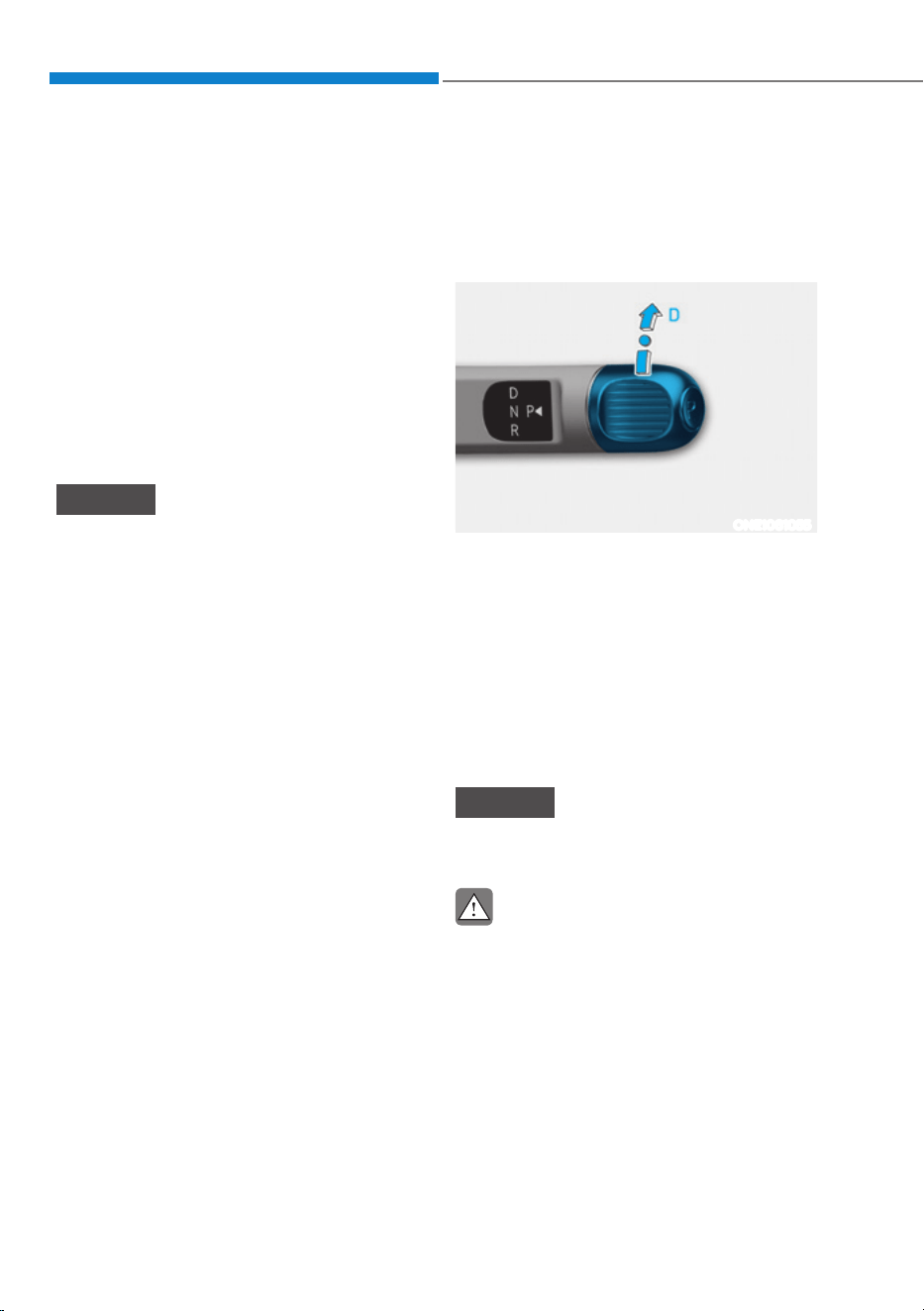
Driving Your Vehicle
6-12
4. Press and hold the OK button on
the steering wheel for more than 1
second.
5. When the message ‘Vehicle will stay in
(N). Change gear to cancel’ (or ‘N will
stay engaged when the vehicle is Off’)
will appear on the cluster LCD display,
press the Start/Stop button while
depressing the brake pedal.
However, if you open the driver’s door
within 3 minutes in the ACC state, the
gear will automatically shift to P (Park)
and the Start/Stop button will change
to the OFF position.
NOTICE
With the gear in N (Neutral) the Start/
Stop button will be in the ACC position.
Note that the doors cannot be locked
in the ACC position or the battery (12V)
may discharge if left in the ACC position
for a long period.
D (Drive)
This is the normal driving position.
The reduction gear automatically
activates the regenerative braking
system according to the road conditions.
ONE1061055
To shift the gear to D (Drive), rotate the
rotary gear shift dial to D (Drive) while
depressing the brake pedal.
When the vehicle is stopped in the D
(Drive) position, if you open the driver's
door, the gear will automatically shift to
P (Park).
However, if the vehicle is in motion, the
gear may not automatically shift to P
(Park) to prevent reduction gear damage.
NOTICE
Always come to a complete stop before
shifting into D (Drive).
CAUTION
When you start after stopping on a steep
incline, even if the gear is in D (Drive),
if you do not depress the accelerator
or brake pedal, the vehicle may roll
backwards, which can cause an accident.
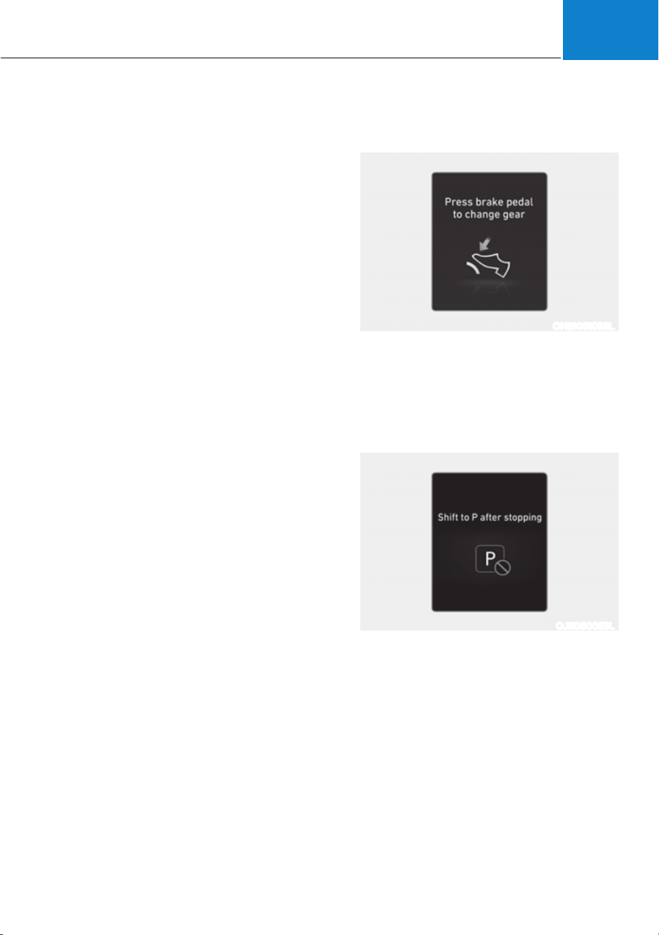
06
6-13
When the battery (12V) is discharged
You cannot shift gears, when the battery
is discharged.
Jump start your vehicle (refer to "Jump
Starting" in chapter 8) or contact an
authorized HYUNDAI dealer.
Parking
Always come to a complete stop and
continue to depress the brake pedal.
Shift the gear to P (Park), apply the
parking brake, and press the Start/Stop
button to the OFF position. Take the Key
with you when leaving the vehicle.
LCD Display Messages (Cluster)
Press brake pedal to change gear
ONE1061038L
This message is displayed when the
brake pedal is not depressed while
shifting the gear.
Depress the brake pedal and then shift
the gear.
Shift to P after stopping
OJK060053L
This message is displayed when the gear
is shifted to P (Park) while the vehicle is
moving.
Stop the vehicle before shifting to P
(Park).
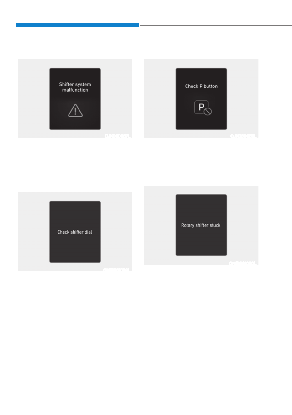
Driving Your Vehicle
6-14
Shifter system malfunction
OJK060057L
This message is displayed when the shift
gear does not properly operate in the P
(Park) position.
Have the vehicle inspected by an
authorized HYUNDAI dealer.
Check shifter dial
ONE1061029L
This message is displayed when there is
a malfunction with the rotary gear shift
dial.
Have the vehicle inspected by an
authorized HYUNDAI dealer.
Check P button
OJK060063L
This message is displayed when there is
a problem with the P button.
Have the vehicle inspected by an
authorized HYUNDAI dealer.
Rotary shifter stuck
ONE1061030L
This message is displayed when the
rotary gear shift dial does not return back
to it’s normal position after rotating it.
Have the vehicle inspected by an
authorized HYUNDAI dealer.

06
6-15
Good Driving Practices
ś Never shift the gear from P (Park) or
N (Neutral) to any other position with
the accelerator pedal depressed.
ś Never shift the gear into P (Park) when
the vehicle is in motion.
Be sure the vehicle is completely
stopped before you attempt to shift
into R (Reverse) or D (Drive).
ś Do not shift the gear to N (Neutral)
when driving. If the gear is shifted to
N (Neutral) while driving. Doing so
may increase the risk of an accident.
Also, shift the gear back to D (Drive)
while the vehicle is moving may
severely damage the reduction gear.
ś When driving uphill or downhill,
always shift to D (Drive) for driving
forward or shift to R (Reverse) for
driving backwards, and check the
gear position indicated on the cluster
or the rotary gear shift dial before
driving. Driving in the opposite
direction of the selected gear, can
lead to a dangerous situation by
shutting off the vehicle and affecting
the braking performance.
ś Do not drive with your foot resting
on the brake pedal. Even light, but
consistent pedal pressure can result
in the brakes overheating, brake wear
and possibly even brake failure.
ś Always apply the parking brake when
leaving the vehicle. Do not depend
on placing the shift gear in P (Park) to
keep the vehicle from moving.
ś Exercise extreme caution when
driving on a slippery surface. Be
especially careful when braking,
accelerating or shifting gears. On a
slippery surface, an abrupt change
in vehicle speed can cause the drive
wheels to lose traction and may cause
loss of vehicle control resulting in an
accident.
ś Optimum vehicle performance and
economy is obtained by smoothly
depressing and releasing the
accelerator.
WARNING
To reduce the risk of SERIOUS INJURY
or DEATH:
ś ALWAYS wear your seat belt. In a
collision, an unbelted occupant
is significantly more likely to be
seriously injured or killed than a
properly belted occupant.
ś Avoid high speeds when cornering or
turning.
ś Do not make quick steering wheel
movements, such as sharp lane
changes or fast, sharp turns.
ś The risk of rollover is greatly
increased if you lose control of your
vehicle at highway speeds.
ś Loss of control often occurs if two or
more wheels drop off the roadway
and the driver over steers to reenter
the roadway.
ś In the event your vehicle leaves
the roadway, do not steer sharply.
Instead, slow down before pulling
back into the travel lanes.
ś HYUNDAI Vehicle recommends you
to follow all posted speed limits.
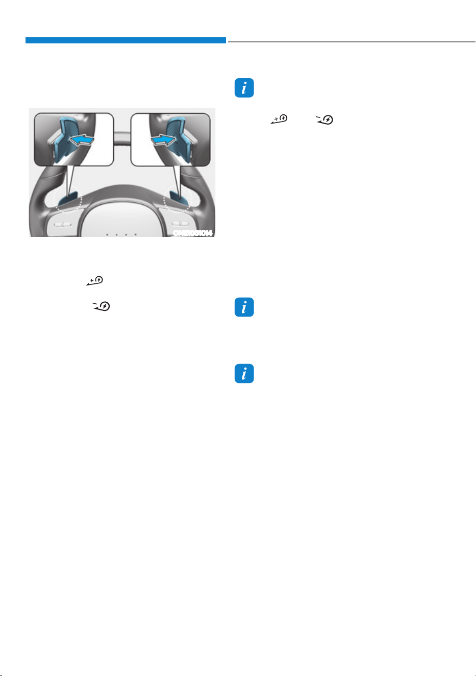
Driving Your Vehicle
6-16
Regenerative braking (Paddle
shifter)
ONE1061014
The paddle shifter is used to adjust the
regenerative braking level from 0 to 3
during decelerating.
ś Left side (
): Increases regenerative
braking and deceleration.
ś Right side ( ): Decreases
regenerative braking and deceleration.
ś Pull and hold the left side paddle
shifter for more than 0.5 seconds
and One pedal driving function is
operated, increasing the regenerative
braking. In this case, stopping the
vehicle is possible by keep on pulling
the paddle shifter.
Refer to the following pages on "One
pedal driving".
ś Pull and hold the right side paddle
shifter for over 1 second to turn on
and off the automatic change of the
regenerative braking.
Refer to the following pages on
"Smart Recuperation System".
Information
The paddle shifter does not operate when:
ś The [
] and [ ] paddle shifters are
pulled at the same time.
ś The vehicle is decelerating by
depressing the brake pedal.
ś The Cruise Control system or Smart
Cruise Control system is activated.
ś Selecting 0 step of the regenerative
braking system, the brake disc cleaning
function is operated around 10 times.
While operating to clean the brake
disc, the driving distance and the
regenerative braking performance
can be reduced. After finishing, the
regenerative braking performance will
be restored.
Information
2WD Long Range vehicles default to level
3 regenerative braking whenever the
vehicle is turned on.
Information
The regenerative braking system on 2WD
Long Range vehicles defaults to Level 3
(L3) in order to maximize vehicle’s all
electric range. This setting will default
to Level 3 (L3) whenever the vehicle is
turned ON. Driver is able to adjust the
regenerative system to their preference
after each vehicle start, but it will only
remain until the vehicle is shut down.
REGENERATIVE BRAKING SYSTEM
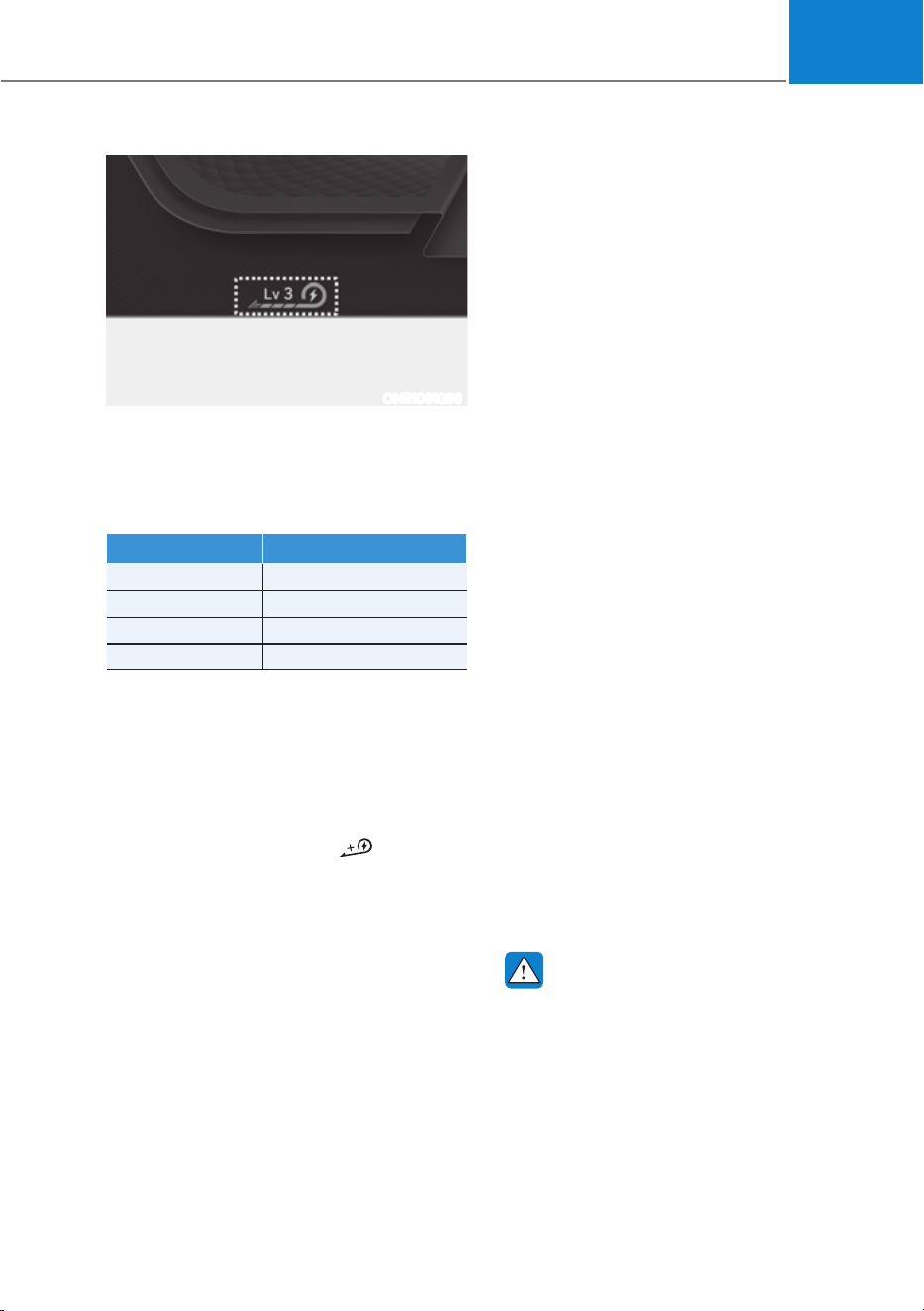
06
6-17
ONE1061036
The selected regenerative braking level is
displayed on the instrument cluster.
Initial setting of the regenerative
braking level and adjustable range vary
according to the selected Drive mode.
Drive mode Adjustable Range
SNOW 0 to 1
ECO 0 to 3
NORMAL 0 to 3
SPORT 0 to 3
For more details, refer to "Drive Mode
Integrated Control System" in this
chapter.
One Pedal Driving
The driver can stop the vehicle by pulling
the left side paddle shifter
.
To operate:
ś Pull and hold the left side paddle
shifter while coasting.
ś When the vehicle speed is above 1.8
mph (3 km/h), release the paddle
shifter to return to the preset
regenerative braking stage.
ś When the vehicle speed is below 1.8
mph (3 km/h), the function maintains
control to stop the vehicle even
though the paddle shifter is released.
ś While the One pedal driving is
operating, the driver can control the
vehicle stopping position using the
accelerator pedal.
Limitations
The vehicle may move even if one pedal
driving is normally operated. Therefore,
the driver should be careful to stop
the vehicle by this function under
circumstances as follows:
- Driving on icy, snowy, wet, sandy,
muddy roads, manhole/pit hole
surfaces
- Wheels not aligned
- Conditions in which wheel slip or spin
occurs
- On heavy loading
- By leaning left of right
- Under bad tire wear
- Driving uphill or downhill
- Driving where the slope starts or ends
- By repeating stop and go on ramp
Automatic engagement of EPB
After the vehicle is stopped by the
One Pedal Driving function, EPB is
automatically engaged when any of
these conditions occur:
ś The driver’s seatbelt is unfastened and
the driver’s door is open.
ś The hood is open.
ś The liftgate is open.
ś 5 minutes have passed after the
vehicle has stopped.
ś The system operation is limited due to
other reasons.
WARNING
ś Stopping the vehicle may not be
possible according to the vehicle and
road conditions. Pay attention to the
road condition ahead and apply the
brake if necessary.
ś Please refrain to use the one pedal
driving function with the road
conditions are bad such as being
wet, iced or covered with snow.

Driving Your Vehicle
6-18
CAUTION
When the vehicle is stopped or parked by
One Pedal Driving on the steep hills, be
sure to depress the brake pedal.
i-Pedal
i-Pedal is controlled by acceleration
pedal. i-Pedal provides vehicle speed
control (acceleration/deceleration,
stopping) without manually controlling
the paddle shifter.
To operate:
ś Pull the left side paddle shifter at level
3 regenerative braking system.
ś During the activation of i-Pedal, the
vehicle is stopped when the vehicle
speed is less than 1 mph (3 km/h) even
if the brake pedal is not pressed.
ś When you press the accelerator pedal
at the same time during one-pedal
driving by pulling the left paddle shift
lever, the vehicle cannot be stopped.
CAUTION
When the vehicle is stopped or parked
by i-Pedal on the steep hills, be sure to
depress the brake pedal.
To deactivate:
ś The i-Pedal is deactivated when the
driver turns off the vehicle. When the
vehicle is turned on, the regenerative
braking is set to be on level 3.
ś The i-Pedal is turned off and the
regenerative braking changes to level
3 when the gear is shifted to R.
Limitations
The vehicle may move even if one pedal
driving is normally operated. Therefore,
the driver should be careful to stop
the vehicle by this function under
circumstances as follows:
- Driving on icy, snowy, wet, sandy,
muddy roads, manhole/pit hole
surfaces
- Wheels not aligned
- Conditions in which wheel slip or spin
occurs
- On heavy loading
- By leaning left of right
- Under bad tire wear
- Driving uphill or downhill
- Driving where the slope starts or ends
- By repeating stop and go on ramp

06
6-19
60$575(&83(5$7,216<67(0
The Smart Recuperation System controls
the regenerative braking automatically
according to the road gradient and
driving condition of the vehicle in front.
The system minimizes the unnecessary
operation of the brake and acceleration
pedal, improving the electric energy
efficiency and assisting the driver.
Smart Recuperation System
Setting
Pull and hold the right side paddle shifter
for over 1 second to turn on and off the
automatic change of the regenerative
braking.
To Activate Smart Recuperation
System
ONE1041017
When Smart Recuperation System
is On in the infotainment system,
‘AUTO’ for the regenerative braking
level is displayed on the cluster. The
regenerative braking level is controlled
automatically when vehicle speed is
above 6 mph (10 km/h) and one of the
condition below is met.
- The road gradient changes
- Distance from the vehicle ahead reduces
or increases
- Speed of the vehicle ahead reduces or
increases
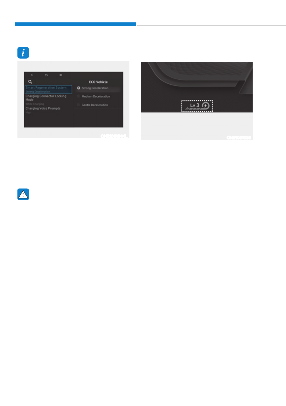
Driving Your Vehicle
6-20
Information
ONE1061044L
The regenerative braking level can
be adjusted based on the driver’s
deceleration style (strong/medium/gentle)
7RDGMXVWWKHOHYHOVHOHFW6HWWLQJVĺ(&2
YHKLFOHĺ6PDUW5HJHQHUDWLRQ6\VWHPLQ
the infotainment system.
WARNING
When vehicle speed is under 6 mph (10
km/h), the Smart Recuperation System
is cancelled. The driver must adjust
the vehicle speed by depressing the
accelerator or brake pedal according to
the road condition ahead and driving
condition.
Smart Recuperation System relies
on front view camera in the vehicle.
Foreign substances on the front view
camera may cause the malfunction of
Smart Recuperation System. Be sure to
maintain clear view for the front view
camera.
The Smart Recuperation System will not
operate when the Forward Collision-
Avoidance Assist (FCA) system warning
light illuminates on the cluster. The
driver must adjust the vehicle speed
by depressing the accelerator or brake
pedal according to the road condition
ahead and driving condition.
Ready to Operate
ONE1061036
Regenerative braking level is displayed
on cluster.
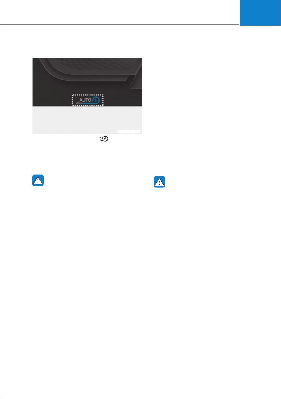
06
6-21
How to Operate
ONE1041017
Pulling the paddle-shift ( ) for 1 or
more seconds, the smart recuperation
system will operate. The indicator of the
regenerative braking will be changed to
'AUTO' from the level indicator.
WARNING
The Smart Recuperation System which
automatically controls the regenerative
braking level when coasting is only a
supplemental system for the driver's
convenience. The system cannot
completely stop the vehicle nor avoid
all collisions. The brake control may
be insufficient depending on the
speed of the vehicle in front and when
the vehicle in front suddenly stops,
a vehicle cuts in suddenly and there
is a steep slope. Always look ahead
cautiously to prevent unexpected and
sudden situations from occurring.
Smart Recuperation System Will
Be Temporarily Cancelled When:
ś Cancelled manually
Pulling and holding the right side
paddle shifter for more than 1 second.
The Smart Recuperation System turns
off temporarily and “AUTO” will be
replaced with regenerative braking
level indicator.
ś Cancelled automatically
- The vehicle is shifted to N (Neutral),
R (Reverse) or P (Park).
- Cruise Control system (including
Smart Cruise Control system) is in
activation.
- The ESC (Electronic Stability
Control) or ABS is operating.
WARNING
When the Smart Recuperation System
is cancelled automatically, adjust the
vehicle speed directly by depressing the
accelerator or brake pedal according to
the road condition ahead and driving
condition.
To Resume Smart Recuperation
System
To re-activate the Smart Recuperation
System while driving, pull and hold the
right side paddle shifter for more than
1 second again. Then, AUTO for the
regenerative braking level will appear on
the cluster.
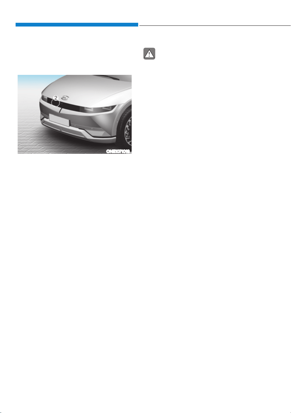
Driving Your Vehicle
6-22
Vehicle-to-Vehicle Distance
Recognition Sensor (Front
Radar)
ONE1071018
[2] : Front radar
For detail location of sensor, refer to the picture
above.
In order for the Smart Recuperation
System to operate properly, always make
sure the radar sensor cover is clean and
free of dirt, snow, and debris. Dirt, snow,
or foreign substances on the lens may
adversely affect the sensing performance
of the sensor. In this case, the system
operation may stop temporarily and not
operate normally.
CAUTION
ś Do not apply license plate frame or
foreign objects such as a bumper
sticker or a bumper guard near the
radar sensor. Doing so may adversely
affect the sensing performance of
the radar.
ś Always keep the radar sensor and
lens cover clean and free of dirt and
debris.
ś Use only a soft cloth to wash the
vehicle. Do not spray pressurized
water directly on the sensor or
sensor cover.
ś Be careful not to apply unnecessary
force on the radar sensor or sensor
cover. If the sensor is forcibly
moved out of proper alignment,
the Smart Recuperation System
may not operate correctly. In this
case, a warning message may not
be displayed. Have the vehicle
inspected by an authorized HYUNDAI
dealer.
ś If the front bumper becomes
damaged in the area around the
radar sensor, the Smart Recuperation
System may not operate properly.
Have the vehicle authorized
HYUNDAI dealer.
ś Use only genuine parts or the
equivalent specified for your vehicle
to repair or replace a damaged
sensor or sensor cover. Do not apply
paint to the sensor cover.
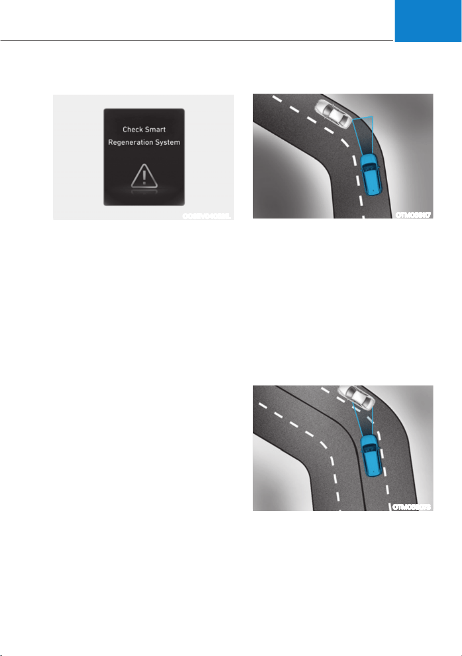
06
6-23
System Malfunction
OOSEV040521L
Check smart recuperation system
The message will appear when the
system is not functioning normally. The
system will be cancelled and the word
'AUTO' on the cluster will disappear and
instead display regenerative braking
level. Check for foreign substances on
the front radar. Remove any dirt, snow, or
foreign material that could interfere with
the radar sensors. If the system still does
not operate normally, take your vehicle
to an authorized HYUNDAI dealer and
have the system checked.
Limitations of the System
The Smart Recuperation System may
not operate properly in certain situations
when the driving condition is beyond the
performance of the front radar sensor.
Driver's attention is required in such
cases when the system does not react
properly or operate unintentionally.
On curves
OTM058117
When coasting on the curve, the system
may not detect the vehicle in your lane
and the regenerative braking level will
reduce automatically, making you feel
that the vehicle is accelerating.
Also, if the system suddenly recognizes
the vehicle in front, the regenerative
braking level will increase automatically,
making you feel that the vehicle is
decelerating.
The driver must maintain a safe braking
distance, and if necessary, depress the
brake pedal to reduce your driving speed
in order to maintain a safe distance.
OTM058073
Your vehicle speed can be reduced due
to a vehicle in the adjacent lane.
Apply the accelerator pedal and select
the appropriate speed. Check to be sure
that the road conditions permit safe
operation of the Smart Recuperation
System.
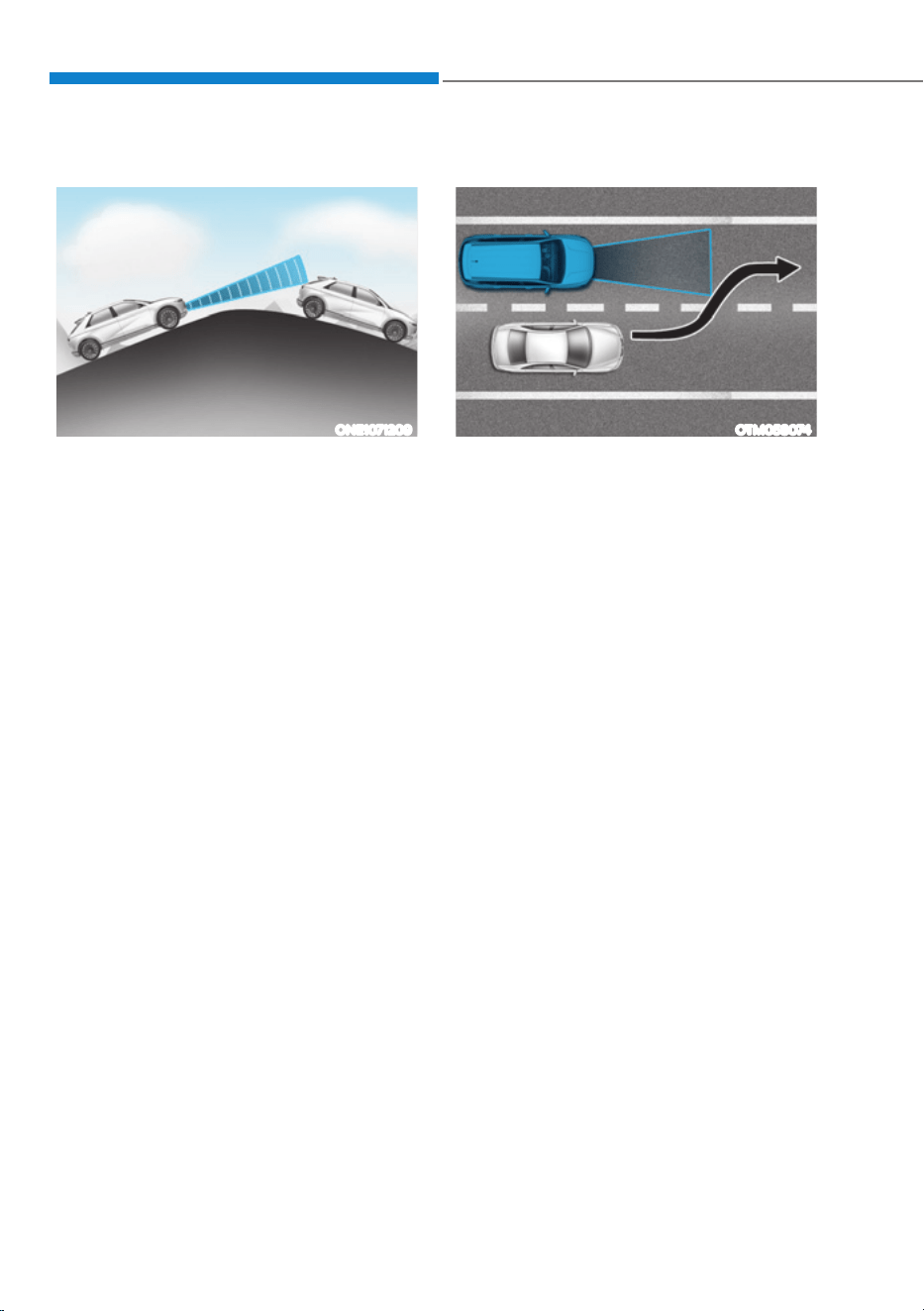
Driving Your Vehicle
6-24
On inclines
ONE1071209
When coasting on an uphill or downhill,
the system may not detect the vehicle in
your lane and the regenerative braking
level will reduce automatically, making
you feel that the vehicle is accelerating.
Also, if the system suddenly recognizes
the vehicle in front, the regenerative
braking level will increase automatically,
making you feel that the vehicle is
decelerating.
The driver must maintain a safe braking
distance, and if necessary, depress the
brake pedal to reduce your driving speed
in order to maintain a safe distance.
Lane changing
OTM058074
ś A vehicle which moves into your lane
from an adjacent lane cannot be
recognized by the sensor until it is in
the sensor's detection range.
ś The radar may not detect immediately
when a vehicle cuts in suddenly.
Always pay attention to the traffic,
road and driving conditions.
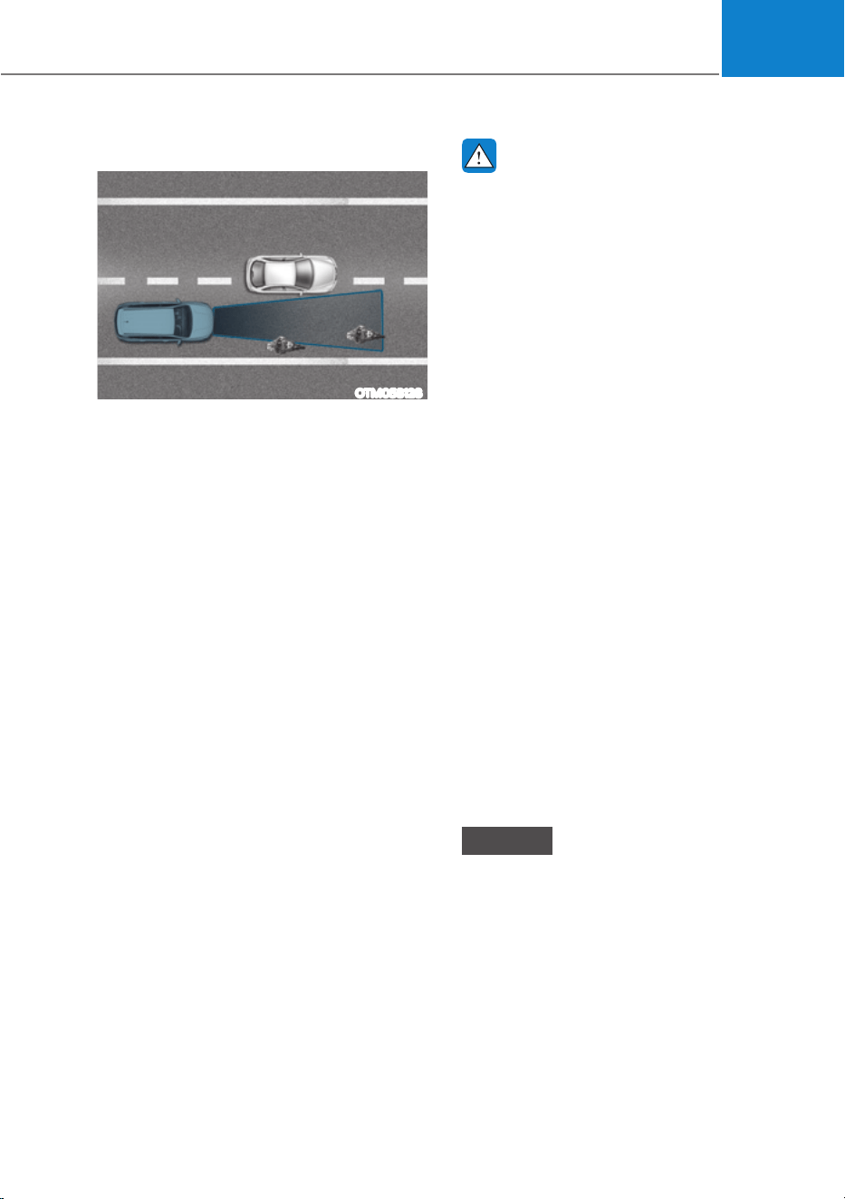
06
6-25
Vehicle recognition
OTM058128
Some vehicles in your lane cannot be
recognized by the sensor:
- Narrow vehicles such as motorcycles or
bicycles
- Vehicles offset to one side
- Slow-moving vehicles or sudden-
decelerating vehicles
- Stopped vehicles (When the vehicle
ahead drives away, the system may not
detect a stopped vehicle.)
- Vehicles with small rear profile such as
trailers with no loads
A vehicle ahead cannot be recognized
correctly by the sensor if any of following
occurs:
- When the vehicle is pointing upwards
due to overloading in the luggage
compartment.
- While the steering wheel is operating.
- When driving to one side of the lane.
- When driving on narrow lanes or on
curves.
- Apply the brake or accelerator pedal if
necessary.
WARNING
When using the Smart Recuperation
System take the following precautions:
ś If an emergency stop is necessary,
you must apply the brakes.
ś Keep a safe distance according to
road conditions and vehicle speed. If
the vehicle to vehicle distance is too
close during a high-speed driving, a
serious collision may result.
ś Always maintain sufficient braking
distance and decelerate your vehicle
by applying the brakes if necessary.
ś The Smart Recuperation System
cannot recognize a stopped vehicle,
pedestrians or an oncoming vehicle.
Always look ahead cautiously to
prevent unexpected and sudden
situations from occurring.
ś Vehicles moving in front of you with
a frequent lane changes may cause
a delay in the system's reaction or
may cause the system to react to a
vehicle actually in an adjacent lane.
Always drive cautiously to prevent
unexpected and sudden situations
from occurring.
ś The Smart Recuperation System
may not recognize complex driving
situations so always pay attention to
driving conditions and control your
vehicle speed.
NOTICE
The Smart Recuperation System may
not operate temporarily due to:
ś Electrical interference
ś Modifying the suspension
ś Differences of tire abrasion or tire
pressure
ś Installing different type of tires
Driving Your Vehicle
6-26
Power-Assist Brakes
Your vehicle has power-assisted brakes
that adjust automatically through normal
usage.
If the vehicle is not running or is turned
off while driving, the power assist for
the brakes will not work. You can still
stop your vehicle by applying greater
force to the brake pedal than typical.
The stopping distance, however, will be
longer than with power brakes.
When the vehicle is not running, the
reserve brake power is partially depleted
each time the brake pedal is applied.
Do not pump the brake pedal when the
power assist has been interrupted.
Information
ś When the brake pedal is depressed
under certain driving conditions
or weather conditions, you may
temporarily hear a noise. This is
normal and does not indicate a problem
with your brakes.
ś While driving on a road with deicing
chemicals, brake noise or abnormal
tire wear may occur due to deicing
chemicals. In a safe traffic condition,
additionally apply the brakes to remove
deicing chemicals on the brake discs
and pads.
WARNING
Take the following precautions:
ś Do not drive with your foot resting
on the brake pedal. This will create
abnormal high brake temperatures,
excessive brake lining and pad wear,
and increased stopping distances.
So increase the regeneration braking
level with the left paddle shift lever
to decrease the speed.
ś When descending down a long or
steep hill, use the paddle shifter to
increase the regeneration braking
level in order to decrease your
speed without using the brake
pedal excessively. Applying the
brakes continuously will cause
the brakes to overheat and could
result in a temporary loss of braking
performance.
ś Wet brakes may impair the vehicle's
ability to safely decelerate. Because
wet brakes increase braking distance
and cause noise troubles, select 0
step of the regenerative braking
system and depress the brake pedal
around 10 times, with keeping the
safe distance from other vehicles,
lightly in order to dry the braking
system. Such procedure may
decrease the driving distance by
restraining the regenerative braking
system, which is not a system
malfunction. Inspect the braking
system after car wash or driving over
wet road conditions.
NOTICE
ś Do not continue depressing
the brake pedal if the "
"
indicator is OFF. The battery may be
discharged.
ś Noise and vibration generated
during braking is normal.
ś Under normal operation, electric
brake pump noise and motor
vibration may occur temporarily in
below cases.
- When the pedal is depressed
suddenly.
- When the pedal is repeatedly
depressed in short intervals.
- When the ABS function is activated
while braking.
BRAKING SYSTEM
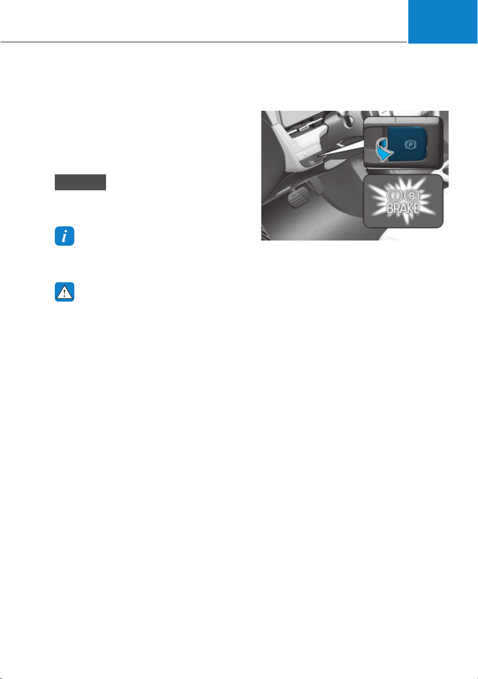
06
6-27
Disc Brakes Wear Indicator
When your brake pads are worn and new
pads are required, you will hear a high
pitched warning sound from your front
or rear brakes. You may hear this sound
come and go or it may occur whenever
you depress the brake pedal.
NOTICE
To avoid costly brake repairs, do not
continue to drive with worn brake pads.
Information
Always replace brake pads as complete
front or rear axle sets.
WARNING
Frequent braking may deform
components and worn the disc brake
causing vibration when braking.
Observe the speed limit to prevent
brake damage from excessive braking.
Brake wear, noise, vibration from
excessive braking or deformation of the
brakes caused by repeatedly braking in
high speed, racing on tracks, etc. can be
excluded from warranty coverage.
Electronic Parking Brake (EPB)
Applying the parking brake
ONE1061015
To apply EPB (Electronic Parking Brake):
1. Depress and hold the brake pedal.
2. Pull up the EPB switch.
Make sure the Parking Brake warning
light comes on.
EPB (Electronic Parking Brake) may be
automatically applied when:
ś Requested by other systems
ś The driver turns the vehicle off while
Auto Hold is operating.
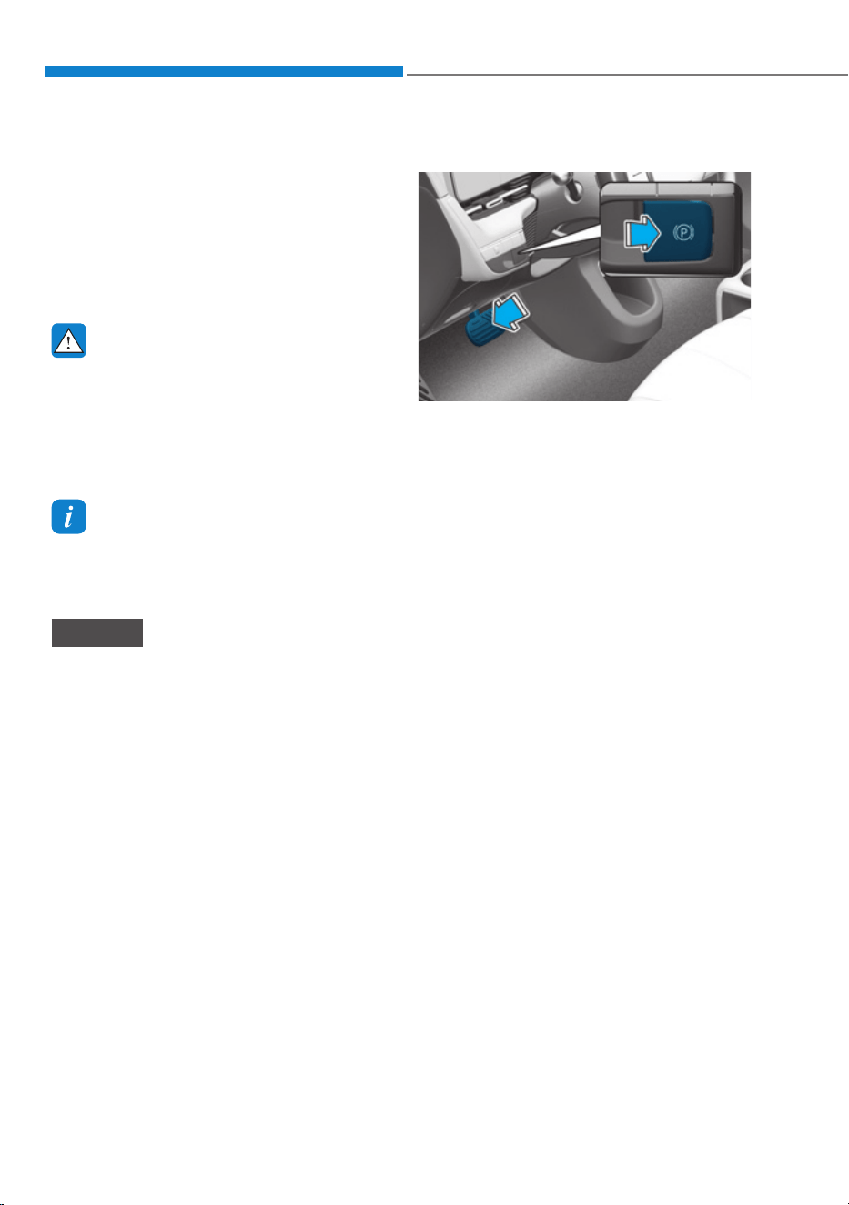
Driving Your Vehicle
6-28
Emergency braking
If there is a problem with the brake
pedal while driving, emergency braking
is possible by pulling up and holding
the EPB switch. Braking is possible only
while you are holding the EPB switch.
However, braking distance will be longer
than normal.
WARNING
To reduce the risk of SERIOUS INJURY
or DEATH, do not operate the EPB
while the vehicle is moving except
in an emergency situation. It could
damage the brake system and lead to
an accident.
Information
During emergency braking, the Parking
Brake warning light will illuminate to
indicate that the system is operating.
NOTICE
If you continuously notice a noise or
burning smell when the EPB is used for
emergency braking, have the system
checked by an authorized HYUNDAI
dealer.
Releasing the parking brake
ONE1061016
To release EPB (Electronic Parking
Brake):
1. Press the Start/Stop button to the ON
or START position.
2. Press the EPB switch while depressing
the brake pedal.
Make sure the Parking Brake warning
light goes off.
To release EPB (Electronic Parking Brake)
automatically:
ś Gear in P (Park)
With the vehicle running depress the
brake pedal and shift out of P (Park) to
R (Reverse) or D (Drive).
ś Gear in N (Neutral)
With the vehicle running depress
the brake pedal and shift out of N
(Neutral) to R (Reverse) or D (Drive).

06
6-29
ś Satisfy the following conditions
1. Ensure seat belts are fastened and the
doors, hood and liftgate are closed.
2. With the vehicle running, depress the
brake pedal and shift out of P (Park) to
R (Reverse), D (Drive) or Manual shift
mode.
3. Depress the accelerator pedal.
Make sure the Parking Brake warning
light goes off.
Information
ś For the Middle East, EPB is released
regardless of seat belt fastening.
ś For your safety, you can engage EPB
even though the Vehicle Stop/Start
button is in the OFF position (only if
battery power is available), but you
cannot release it.
ś For your safety, depress the brake
pedal and release the parking brake
manually with the EPB switch when
you drive downhill or when backing up
the vehicle.
NOTICE
ś If the Parking Brake warning light is
still on even though the EPB has been
released, have the system checked
by an authorized HYUNDAI dealer.
ś Do not drive your vehicle with EPB
applied. It may cause excessive brake
pad and brake rotor wear.
Warning messages
OJK060066L
To release EPB, close the doors, hood and
liftgate and fasten the seatbelt
ś If you try to drive with EPB applied, a
warning will sound and a message will
appear.
ś If the driver's seat belt is unfastened
and the hood or liftgate is opened, a
warning will sound and a message will
appear.
ś If there is a problem with the vehicle,
a warning may sound and a message
may appear.
If the situation occurs, depress the brake
pedal and release EPB by pressing the
EPB switch.

Driving Your Vehicle
6-30
WARNING
ś Whenever leaving the vehicle or
parking, always come to a complete
stop and continue to depress the
brake pedal.
Shift the gear into P (Park), pull the
EPB switch, and press the Start/Stop
button to the OFF position. Take
the Key with you when leaving the
vehicle.
Vehicles not fully engaged in P (Park)
with the parking brake set are at risk
for moving inadvertently and causing
injury to yourself or others.
ś NEVER allow anyone who is
unfamiliar with the vehicle to touch
the EPB switch. If EPB is released
unintentionally, serious injury may
occur.
ś Only release EPB when you are
seated inside the vehicle with your
foot firmly on the brake pedal.
NOTICE
ś Do not apply the accelerator pedal
while the parking brake is engaged.
If you depress the accelerator pedal
with EPB engaged, a warning will
sound and a message will appear.
Damage to the parking brake may
occur.
ś Driving with the parking brake on
can overheat the braking system and
cause premature wear or damage
to brake parts. Make sure EPB is
released and the Parking Brake
warning light is off before driving.
Information
ś A clicking sound may be heard while
operating or releasing the EPB. These
conditions are normal and indicate that
EPB is functioning properly.
ś When leaving your keys with a parking
attendant or assistant, make sure to
inform him/her how to operate EPB.
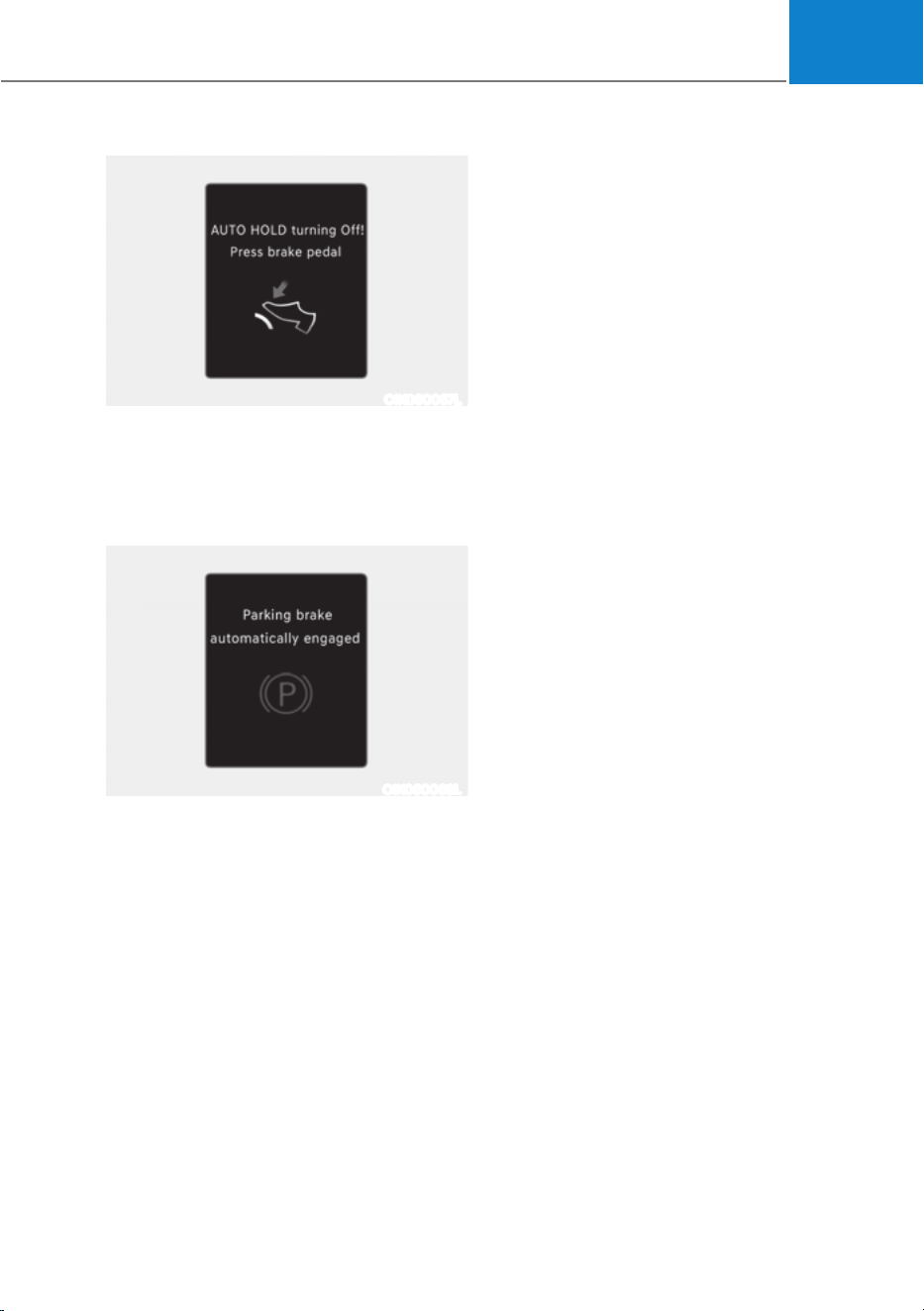
06
6-31
OIK060067L
AUTO HOLD turning Off! Press brake
pedal
When the conversion from Auto Hold to
EPB is not working properly a warning
will sound and a message will appear.
OIK060069L
Parking brake automatically engaged
When EPB is applied while Auto Hold
is activated, a warning will sound and a
message will appear.
EPB malfunction
Electronic Parking Brake (EPB) warning
light illuminates if the Start/Stop button
is pressed to the ON position and goes
off in approximately 3 seconds if the
system is operating normally.
If the EPB warning light remains on,
comes on while driving, or does not
come on when the Start/Stop button is
pressed to the ON position, this indicates
that the EPB may have malfunctioned.
If this occurs, have the system checked
by an authorized HYUNDAI dealer.
The EPB warning light may illuminate
when the ESC indicator comes on to
indicate that ESC is not working properly,
but it does not indicate a malfunction of
EPB.
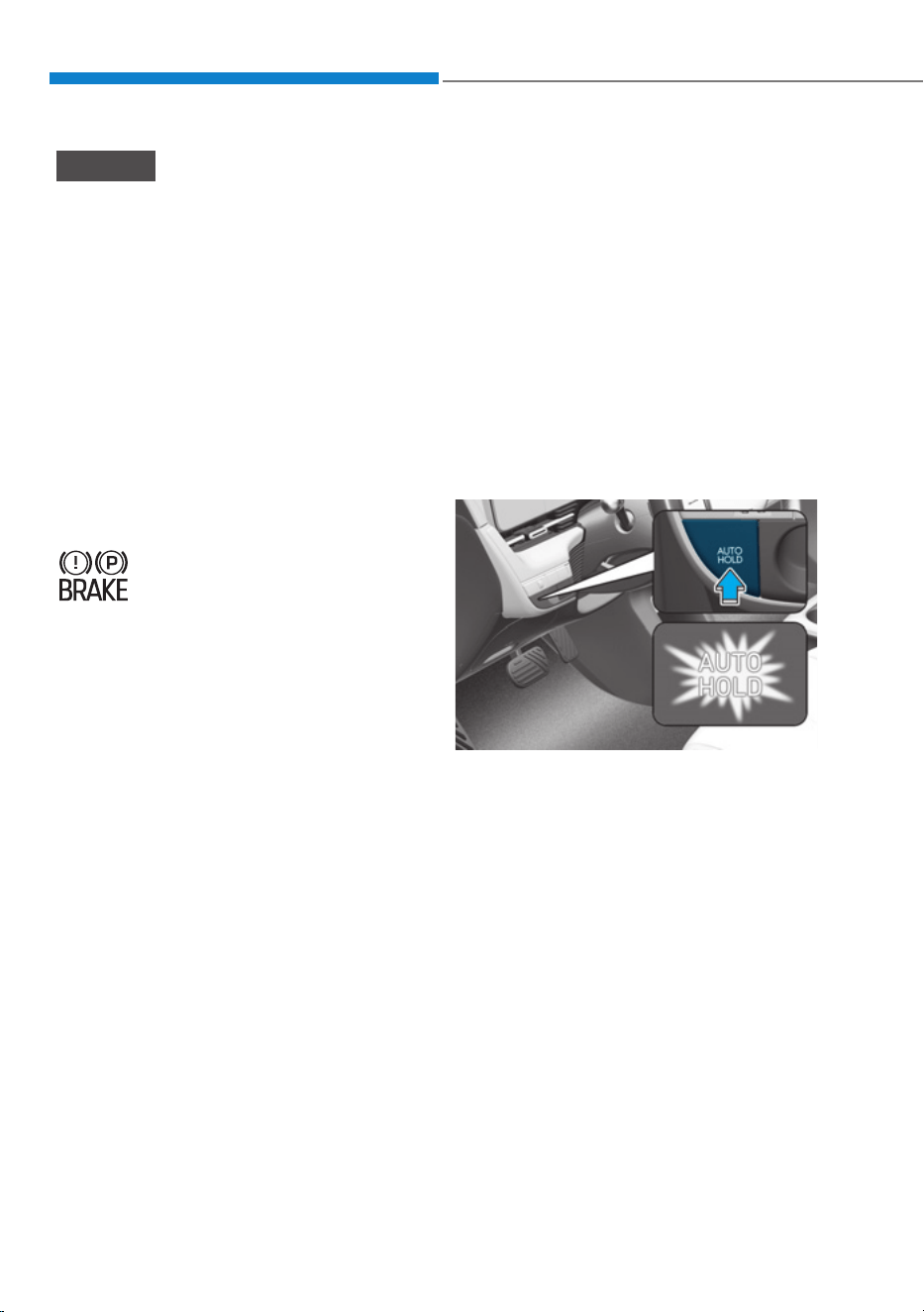
Driving Your Vehicle
6-32
NOTICE
ś If the EPB warning light is still on,
have the system checked by an
authorized HYUNDAI dealer.
ś If the Parking Brake warning light
does not illuminate or blinks even
though the EPB switch was pulled
up, EPB may not be applied.
ś If the Parking Brake warning light
blinks when the EPB warning light is
on, press the switch, and then pull it
up. Repeat this one more time. If the
EPB warning does not go off, have
the system checked by an authorized
HYUNDAI dealer.
Parking brake warning light
Check the Parking Brake
warning light by pressing the
Vehicle Stop/Start button to the
ON position.
This light will be illuminated when the
parking brake is applied with the Vehicle
Stop/Start button in the START or ON
position.
Before driving, be sure the parking
brake is released and the Parking Brake
warning light is OFF.
If the Parking Brake warning light
remains on after the parking brake is
released while the motor is running,
there may be a malfunction in the
brake system. Immediate attention is
necessary.
If at all possible, cease driving the vehicle
immediately. If that is not possible,
use extreme caution while operating
the vehicle and only continue to drive
the vehicle until you can reach a safe
location.
When the EPB (Electronic Parking
Brake) does not release
If the EPB does not release normally,
contact an authorized HYUNDAI dealer
by loading the vehicle on a flatbed tow
truck and have the system checked.
Auto Hold
Auto Hold maintains the vehicle in a
standstill even though the brake pedal is
not depressed after the driver brings the
vehicle to a complete stop by depressing
the brake pedal.
To apply:
ONE1061017
1. With the driver's door and hood
closed, depress the brake pedal and
then press the AUTO HOLD switch.
The white AUTO HOLD indicator will
come on and the system will be in the
standby position.
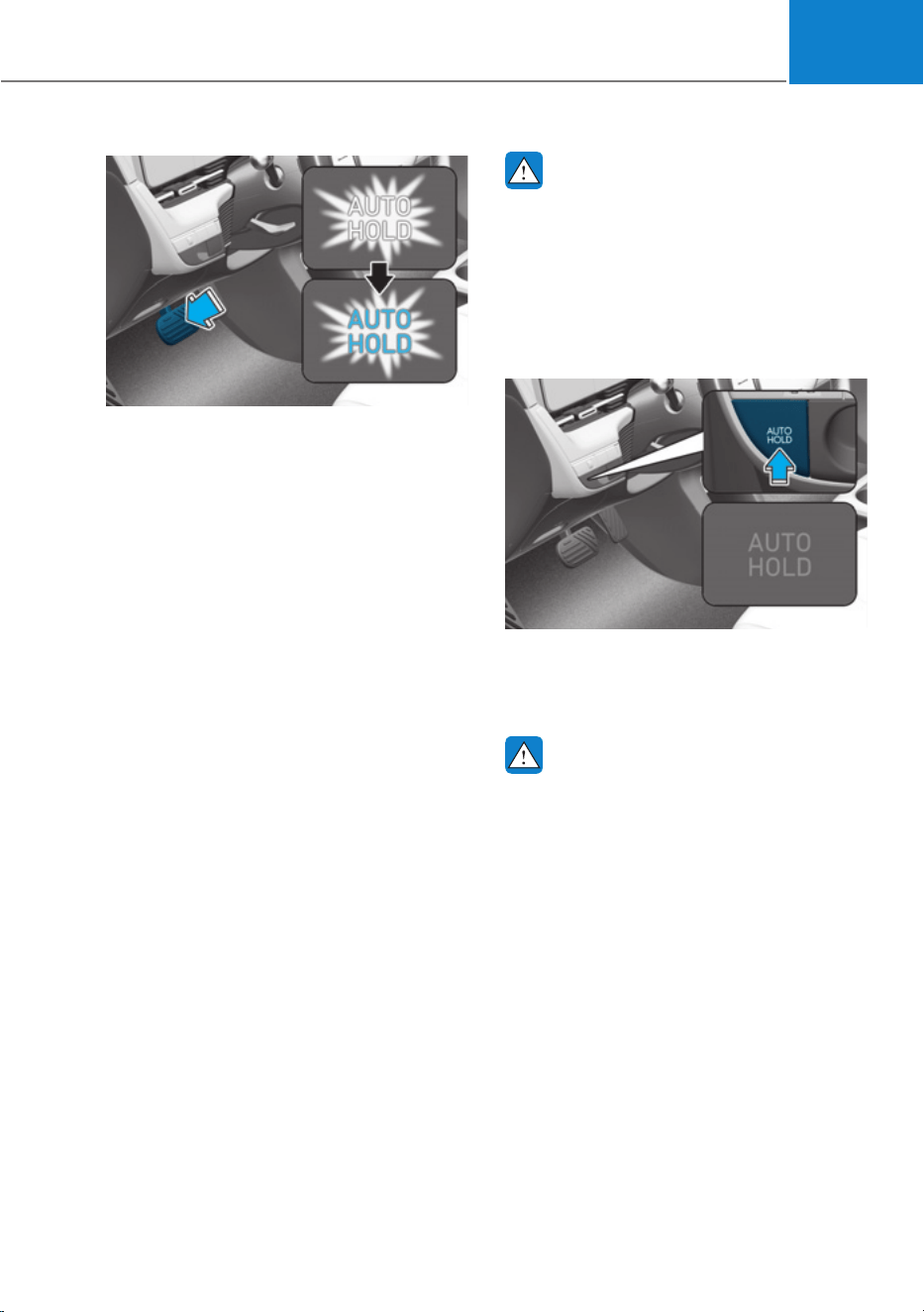
06
6-33
ONE1061018
2. When you stop the vehicle completely
by depressing the brake pedal, Auto
Hold maintains the brake pressure
to hold the vehicle stationary. The
indicator changes from white to
green.
3. The vehicle will remain stationary
even if you release the brake pedal.
4. If EPB is applied, Auto Hold will be
released.
To release:
If you depress the accelerator pedal
with the gear in D (Drive) or Manual shift
mode, the Auto Hold will be released
automatically and the vehicle will start
to move. The AUTO HOLD indicator
changes from green to white.
WARNING
When Auto Hold is automatically
released by depressing the accelerator
pedal, always take a look around your
vehicle.
Slowly depress the accelerator pedal
for a smooth start.
To cancel:
ONE1061019
1. Depress and hold the brake pedal.
2. Press the AUTO HOLD switch.
The AUTO HOLD indicator will turn off.
WARNING
To prevent, unexpected and sudden
vehicle movement, ALWAYS press your
foot on the brake pedal to cancel the
Auto Hold before you:
- Drive downhill.
- Drive the vehicle in R (Reverse).
- Park the vehicle.
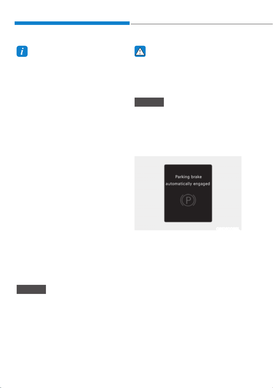
Driving Your Vehicle
6-34
Information
ś The Auto Hold does not operate when:
- The gear is in P (Park)
- EPB is applied
ś For your safety, the Auto Hold
automatically switches to EPB when:
- The driver's door is opened
- The tail gate is opened
- The hood is opened
- The vehicle is in a standstill for more
than 10 minutes
- The vehicle is standing on a steep
slope
- The vehicle moved several times
In these cases, the Parking Brake
warning light comes on, the AUTO
HOLD indicator changes from green
to white, and a warning sound and a
message will appear to inform you that
EPB has been automatically engaged.
Before driving off again, depress the
brake pedal, check the surrounding
area near your vehicle and release the
parking brake manually with the EPB
switch.
ś While operating Auto Hold, you may
hear mechanical noise. However, it is
normal operating noise.
ś If the vehicle is restarted with the Auto
Hold system is in the standby position
or operating, the Auto hold system
will continue to operate in the standby
position.
NOTICE
If the AUTO HOLD indicator changes
to yellow, Auto Hold is not working
properly. Contact an authorized
HYUNDAI dealer.
WARNING
ś Depress the accelerator pedal slowly
when you start the vehicle.
ś For your safety, cancel Auto Hold
when you drive downhill, back up the
vehicle or park the vehicle.
NOTICE
If there is a malfunction with the
driver's door or hood open detection
system, Auto Hold may not work
properly.
Contact an authorized HYUNDAI dealer.
Warning messages
OIK060069L
Parking brake automatically engaged
When EPB is applied while Auto Hold
is activated, a warning will sound and a
message will appear.
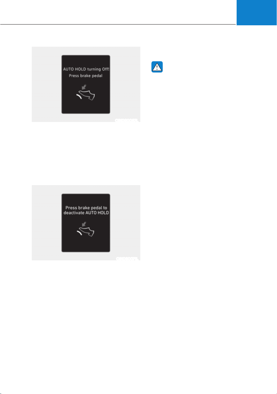
06
6-35
OIK060067L
AUTO HOLD turning Off! Press brake
pedal
When the conversion from Auto Hold to
EPB is not working properly a warning
will sound and a message will appear.
When this message is displayed, Auto
Hold and EPB may not operate. For your
safety, depress the brake pedal.
OIK060071L
Press brake pedal to deactivate AUTO
HOLD
If you did not apply the brake pedal when
you release Auto Hold by pressing the
AUTO HOLD switch, a warning will sound
and a message will appear.
Anti-Lock Brake System (ABS)
WARNING
Anti-Lock Braking System (ABS) or
Electronic Stability Control (ESC)
system will not prevent accidents
due to improper or dangerous driving
maneuvers. Even though vehicle
control is improved during emergency
braking, always maintain a safe
distance between you and objects
ahead of you. Vehicle speeds should
always be reduced during extreme
road conditions. The braking distance
for vehicles equipped with ABS or ESC
may be longer than for those without
these systems in the following road
conditions.
Drive your vehicle at reduced speeds
during the following conditions:
ś Rough, gravel or snow-covered
roads.
ś On roads where the road surface is
pitted or has different surface height.
ś Tire chains are installed on your
vehicle.
The safety features of ABS or ESC
equipped vehicle should not be tested
by high speed driving or cornering. This
could endanger the safety of yourself or
others.
ABS is an electronic braking system that
helps prevent a braking skid. ABS allows
the driver to steer and brake at the same
time.

Driving Your Vehicle
6-36
Using ABS
To obtain the maximum benefit from
your ABS in an emergency situation,
do not attempt to modulate your brake
pressure and do not try to pump your
brakes. Depress your brake pedal as hard
as possible.
When you apply your brakes under
conditions which may lock the wheels,
you may hear sounds from the brakes,
or feel a corresponding sensation in the
brake pedal. This is normal and it means
your ABS is active.
ABS does not reduce the time or distance
it takes to stop the vehicle.
Always maintain a safe distance from the
vehicle in front of you.
ABS will not prevent a skid that results
from sudden changes in direction, such
as trying to take a corner too fast or
making a sudden lane change. Always
drive at a safe speed for the road and
weather conditions.
ABS cannot prevent a loss of stability.
Always steer moderately when braking
hard. Severe or sharp steering wheel
movement can still cause your vehicle to
veer into oncoming traffic or off the road.
On loose or uneven road surfaces,
operation of the anti-lock brake system
may result in a longer stopping distance
than for vehicles equipped with a
conventional brake system.
The ABS (
) warning light will stay on
for several seconds after the Start/Stop
button is in the ON position.
During that time, ABS will go through
self-diagnosis and the light will go off if
everything is normal. If the light stays on,
you may have a problem with your ABS.
Contact an authorized HYUNDAI dealer
as soon as possible.
WARNING
If the ABS ( ) warning light is on and
stays on, you may have a problem with
the ABS. Your power brakes will work
normally. To reduce the risk of serious
injury or death, contact your authorized
HYUNDAI dealer as soon as possible.
NOTICE
When you drive on a road having poor
traction, such as an icy road, and apply
your brakes continuously, ABS will be
active continuously and the ABS (
)
warning light may illuminate. Pull your
vehicle over to a safe place and turn the
vehicle off.
Restart the vehicle. If the ABS warning
light is off, then your ABS system is
normal.
Otherwise, you may have a problem
with your ABS system. Contact an
authorized HYUNDAI dealer as soon as
possible.
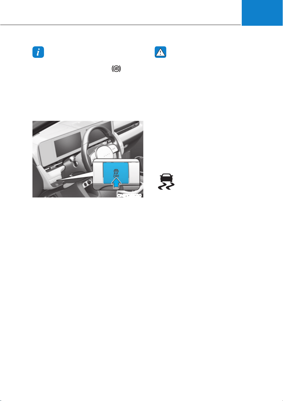
06
6-37
Information
When you jump start your vehicle because
of a drained battery, the ABS (
)
warning light may turn on at the same
time. This happens because of the low
battery voltage. It does not mean your
ABS is malfunctioning. Have the battery
recharged before driving the vehicle.
Electronic Stability Control (ESC)
ONE1061020
Electronic Stability Control helps to
stabilize the vehicle during cornering
maneuvers.
ESC checks where you are steering and
where the vehicle is actually going. ESC
applies braking pressure to any one of
the vehicle's brakes and intervenes in the
electric vehicle control system to assist
the driver with keeping the vehicle on the
intended path. It is not a substitute for
safe driving practices. Always adjust your
speed and driving to the road conditions.
WARNING
Never drive too fast for the road
conditions when cornering. ESC will not
prevent accidents.
Excessive speed in turns, abrupt
maneuvers, and hydroplaning on wet
surfaces can result in severe accidents.
ESC operation
ESC ON condition
When the Start/Stop button is in the ON
position, ESC and the ESC OFF indicator
lights illuminate for approximately three
seconds. After both lights go off, ESC is
enabled.
When operating
When ESC is in operation, the
ESC indicator light blinks:
ś When you apply your brakes under
conditions which may lock the wheels,
you may hear sounds from the brakes,
or feel a corresponding sensation in
the brake pedal. This is normal and it
means your ESC is active.
ś When ESC activates, the vehicle may
not respond to the accelerator as it
does under routine conditions.
ś If Cruise Control was in use when ESC
activates, Cruise Control automatically
disengages. Cruise Control can be
reengaged when the road conditions
allow. See “Cruise Control System”
section in chapter 7 (if equipped).
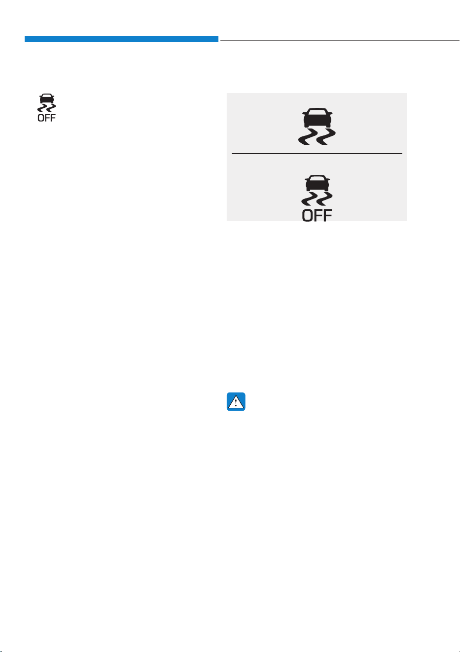
Driving Your Vehicle
6-38
ESC OFF condition
To cancel ESC operation:
ś State 1
Press the ESC OFF button briefly.
The ESC OFF indicator light and/or
message 'Traction Control disabled'
will illuminate. In this state, the traction
control function of ESC (electric vehicle
control management) is disabled, but the
brake control function of ESC (braking
management) still operates.
ś State 2
Press and hold the ESC OFF button
continuously for more than 3 seconds.
The ESC OFF indicator light and/or
message 'Traction & Stability Control
disabled' illuminates and a warning
chime sounds. In this state, both the
traction control function of ESC (electric
vehicle control management) and the
brake control function of ESC (braking
management) are disabled.
If the Start/Stop button is pressed to
the OFF position when ESC is off, ESC
remains off. Upon restarting the vehicle,
ESC will automatically turn on again.
When ESC (electric vehicle control) is
deactivated, the vehicle will loose the
traction and stability if the vehicle is
driven by abrupt steering wheel control.
It is possible that the tire may make a
collision with the connected parts of the
tire. We recommend to do not turn off
ESC while driving the vehicle for your
safety.
Indicator lights
Ŷ
ESC indicator light (blinks)
Ŷ
ESC OFF indicator light (comes on)
When the Start/Stop button is pressed
to the ON position, the ESC indicator
light illuminates, then goes off if the ESC
system is operating normally.
The ESC indicator light blinks whenever
ESC is operating.
If the ESC indicator light stays on, your
vehicle may have a malfunction with
the ESC system. When this warning light
illuminates , have the vehicle checked by
an authorized HYUNDAI dealer as soon
as possible.
The ESC OFF indicator light comes on
when ESC is turned off.
WARNING
When ESC is blinking, this indicates ESC
is active:
Drive slowly and NEVER attempt to
accelerate. NEVER turn ESC off while
the ESC indicator light is blinking or you
may lose control of the vehicle resulting
in an accident.

06
6-39
NOTICE
Driving with wheels and tires with
different sizes may cause the ESC
system to malfunction. Before replacing
tires, make sure all four tires and wheels
are the same size. Never drive the
vehicle with different sized wheels and
tires installed.
ESC OFF usage
When Driving
The ESC OFF mode should only be used
briefly to help free the vehicle if stuck in
snow or mud, by temporarily stopping
operation of ESC, to maintain wheel
torque.
To turn ESC off while driving, press the
ESC OFF button while driving on a flat
road surface.
NOTICE
To prevent damage to the reduction
gear:
ś Do not allow wheel(s) of one axle to
spin excessively while the ESC, ABS,
and Parking Brake warning lights
are displayed. The repairs would not
be covered by the vehicle warranty.
Reduce motor power and do not spin
the wheel(s) excessively while these
lights are displayed.
ś When operating the vehicle
on a dynamometer, make sure
ESC is turned off (ESC OFF light
illuminated).
Information
ś Turning ESC off does not affect ABS or
standard brake system operation.
ś Select 0 step of the regenerative
braking system and depress the brake
pedal around 10 times to efficiently
apply brake disc cleaning.
Brake disc cleaning may decrease the
driving distance by restraining the
regenerative braking system. After
brake disc cleaning, the regenerative
braking system may be restored.
If the regenerative braking system
is not restored after the brake disc
cleaning, have the vehicle inspected by
an authorized HYUNDAI dealer.

Driving Your Vehicle
6-40
Vehicle Stability Management
(VSM)
Vehicle Stability Management is a
function of the Electronic Stability
Control (ESC) system. It helps the vehicle
stay stable when accelerating or braking
suddenly on wet, slippery and rough
roads where traction over the four tires
can suddenly become uneven.
WARNING
Take the following precautions when
using Vehicle Stability Management:
ś ALWAYS check the speed and the
distance to the vehicle ahead. VSM
is not a substitute for safe driving
practices.
ś Never drive too fast for the road
conditions. VSM will not prevent
accidents. Excessive speed in bad
weather, on slippery and uneven
roads can result in severe accidents.
VSM operation
When operating
When you apply your brakes under
conditions which may activate ESC, you
may hear sounds from the brakes, or feel
a corresponding sensation in the brake
pedal. This is normal and it means your
VSM is active.
Information
VSM does not operate when:
ś Driving on a banked road such as
gradient or incline.
ś Driving in reverse.
ś The ESC OFF indicator light is on.
ś The EPS (Electric power steering)
warning light (
) is on or blinks.
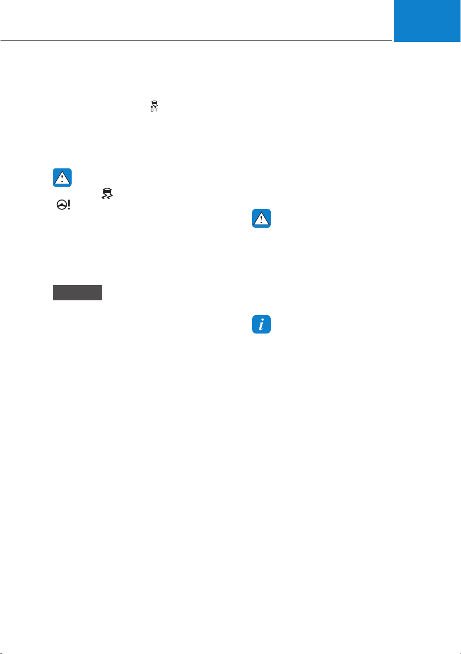
06
6-41
VSM OFF condition
To cancel VSM operation, press the ESC
OFF button. ESC OFF (
) indicator light
will illuminate.
To turn on VSM, press the ESC OFF
button again. The ESC OFF indicator light
will go out.
WARNING
If the ESC ( ) indicator light or EPS
(
) warning light stays illuminated
or blinks, your vehicle may have a
malfunction with the VSM system.
When the warning light illuminates
have the vehicle checked by an
authorized HYUNDAI dealer as soon as
possible.
NOTICE
Driving with wheels and tires with
different sizes may cause the VSM
system to malfunction. Before replacing
tires, make sure all four tires and wheels
are the same size. Never drive the
vehicle with different sized tires and
wheels installed.
Hill-Start Assist Control (HAC)
Hill-Start Assist Control helps prevent
the vehicle from rolling backwards
when starting a vehicle from a stop
on a hill. The system operates the
brakes automatically for approximately
2 seconds (maximum of 5 seconds
when the accelerator pedal is slightly
depressed during HAC operation) and
releases the brake after 2 seconds or
when the accelerator pedal is depressed.
WARNING
Always be ready to depress the
accelerator pedal when starting off
an incline. Hill-Start Assist Control
activates only for approximately 2
seconds (maximum of 5 seconds
when the accelerator pedal is slightly
depressed during HAC operation).
Information
ś Hill-Start Assist Control does not
operate when the gear is shifted to P
(Park) or N (Neutral).
ś Hill-Start Assist Control activates even
when the ESC (Electronic Stability
Control) is off. However, it does not
activate, when ESC does not operate
normally.

Driving Your Vehicle
6-42
Good Braking Practices
WARNING
Whenever leaving the vehicle or
parking, always come to a complete
stop and continue to depress the brake
pedal. Shift the gear to the P (Park)
position, then apply the parking brake,
and press the Start/Stop button to the
OFF position.
Vehicles parked with the parking brake
not applied or not fully engaged may
roll inadvertently and may cause injury
to the driver and others. ALWAYS apply
the parking brake before exiting the
vehicle.
Be aware of wet brakes. The brakes may
get wet if the vehicle is driven through
standing water or if it is washed. Your
vehicle will not stop as quickly if the
brakes are wet. Wet brakes may cause
the vehicle to pull to one side.
To dry the brakes, apply the brakes
lightly until the braking action returns to
normal. If the braking action does not
return to normal, stop as soon as it is safe
to do so and call an authorized HYUNDAI
dealer for assistance.
DO NOT drive with your foot resting on
the brake pedal. Even light, but constant
pedal pressure can result in the brakes
overheating, brake wear, and possibly
even brake failure.
If a tire goes flat while you are driving,
apply the brakes gently and keep the
vehicle pointed straight ahead while you
slow down. When you are moving slowly
enough for it to be safe to do so, pull off
the road and stop in a safe location.
Keep your foot firmly on the brake pedal
when the vehicle is stopped to prevent
the vehicle from rolling forward.

06
6-43
When All Wheel Drive(AWD) is
activated, driving forces are distributed
appropriately to front and rear wheels.
It could improve driving performance by
maximizing the driving force of vehicles
on severe road conditions such as steep
hills, unpaved, slippery, etc.
Advantage of electronic AWD
1. Improvement of straight stability
2. Improvement of driving performance
on curve
3. Secure stability on severe condition
such as wet and sandy roads.
4. Improvement of energy efficiency
from driving mode automatic control.
Information
AWD vehicles could change the
engagement status of the motor according
to the situation required. Auto changing
the driving mode(2WD/AWD)helps
improve energy efficiency and driving
stability.
WARNING
To reduce the risk of SERIOUS INJURY
or DEATH:
ś Avoid high speeds when cornering or
turning.
ś Do not make quick steering wheel
movements, such as sharp lane
changes or fast, sharp turns.
ś The risk of a rollover is greatly
increased if you lose control of your
vehicle at highway speeds.
ś Loss of control often occurs if two or
more wheels drop off the roadway
and the driver over steers to reenter
the roadway.
ś In the event your vehicle leaves
the roadway, do not steer sharply.
Instead, slow down before pulling
back into the travel lanes.
NOTICE
ś Do not drive in water if the level
is higher than the bottom of the
vehicle.
ś Check your brake condition once
you are out of mud or water. Depress
the brake pedal several times as you
move slowly until you feel normal
braking return.
ś Shorten your scheduled
maintenance interval if you drive in
off-road conditions such as sand,
mud or water (see "Maintenance
Under Severe Usage Conditions"
section in chapter 9).
ś Always wash your vehicle thoroughly
after off road use, especially the
bottom of the vehicle.
ś Be sure to equip the vehicle with four
tires of the same size and type.
ś Make sure that a full time AWD
vehicle is towed by a flat bed tow
truck.
$//:+((/'5,9(ǣ$:'Ǥǣ,)(48,33('Ǥ

Driving Your Vehicle
6-44
For safe AWD operation
Before driving
ś Make sure all passengers are wearing
seat belts.
ś Sit upright and closer to the steering
wheel than usual. Adjust the steering
wheel to a position comfortable for
you to drive.
Driving on snow-covered or icy roads
ś Start off slowly by applying the
accelerator pedal gently.
ś Use snow tires or tire chains.
ś Keep sufficient distance between your
vehicle and the vehicle in front of you.
ś Using regenerative braking helps the
steering on the downhill. However, it
may be difficult to adjust the vehicle
while coasting using regenerative
braking, so avoid using the third level
of regenerative braking as much as
possible.
ś Avoid speeding, rapid acceleration,
sudden brake applications, and sharp
turns to prevent skids.
ś It is difficult to start again if the
vehicle stops on an uphill road. Keep
your distance from other vehicles and
drive slowly.
Information
When using Snow Tires, mount them on
all four wheels.
When using tire chains, install them on the
rear tires.
However, driving speed must be below 30
km/h and minimize the driving distance.
High-speed or long-term driving with
tire chains installed may malfunction or
damage the AWD system.
For more details on Snow Tires and Tire
Chains, refer to "Winter Driving" section
later in this chapter.
Driving in sand or mud
ś Maintain slow and constant speed.
ś Use tire chains driving in mud if
necessary.
ś Keep sufficient distance between your
vehicle and the vehicle in front of you.
ś Reduce vehicle speed and always
check the road condition.
ś Avoid speeding, rapid acceleration,
sudden brake applications, and sharp
turns to prevent getting stuck.
NOTICE
When the vehicle is stuck in snow, sand
or mud, place a nonslip material under
the drive wheels to provide traction
OR slowly spin the wheels in forward
and reverse directions which causes
a rocking motion that may free the
vehicle.
Driving up or down hills
ś Driving uphill
- Before starting off, check if it is
possible to drive uphill.
- Drive as straight as possible.
ś Driving downhill
- Do not change gear while driving
downhill. Select gear before driving
downhill.
- Drive straight as possible.
WARNING
Exercise extreme caution driving up or
down steep hills. The vehicle may flip
over depending on the grade, terrain,
water and mud conditions.

06
6-45
WARNING
Do not drive across the contour of steep
hills. A slight change in the wheel angle
can destabilize the vehicle, or a stable
vehicle may lose stability if the vehicle
stops its forward motion. Your vehicle
may roll over and lead to a serious injury
or death.
Additional driving conditions
ś Become familiar with the off-road
conditions before driving.
ś Always pay attention when driving off-
road and avoid dangerous areas.
ś Drive slowly when driving in heavy
wind.
ś Reduce vehicle speed when
cornering. The center of gravity
of AWD vehicles is higher than
conventional 2WD vehicles, making
them more likely to roll over when you
rapidly turn corners.
ś Always hold the steering wheel firmly
when you are driving off-road.
WARNING
Do not grab the inside of the steering
wheel when you are driving off-road.
You may hurt your arm by a sudden
steering maneuver or from steering
wheel rebound due to an impact with
objects on the ground. You could lose
control of the steering wheel which may
lead to serious injury or death.
Emergency Precautions
Tires
When replacing tires, be sure to equip
all four tires with the same size, type,
tread patterns, brand and load-carrying
capacity.
WARNING
Do not use tire and wheel with different
size and type from the one originally
installed on your vehicle. It can affect
the safety and performance of your
vehicle, which could lead to steering
failure or rollover causing serious injury.
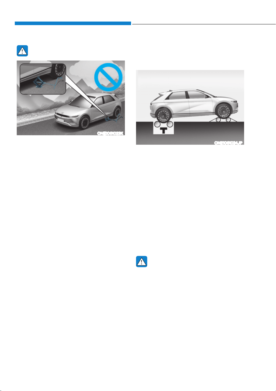
Driving Your Vehicle
6-46
WARNING
ONE1061023K
Never start or run the vehicle while
an AWD vehicle is raised on a jack.
The vehicle can slip or roll off of a jack
causing serious injury or death to you or
those nearby.
Towing
AWD vehicles must be towed with
a wheel lift and dollies or flatbed
equipment with all the wheels off the
ground. For more details, refer to
"Towing" section in chapter 8.
Vehicle inspection
ś If the vehicle needs to be operated on
a vehicle lift do not attempt to stop
any of the four wheels from turning.
This could damage the AWD system.
ś Never engage the parking brake while
running the vehicle on a car lift. This
may damage the AWD system.
Dynamometer testing
An AWD vehicle must be tested on a
special four wheel chassis dynamometer.
ONE1061024JP
[A] : Roll tester (Speedometer),
[B] : Temporary free roller
An AWD vehicle should not be tested
on a 2WD roll tester. If a 2WD roll tester
must be used, perform the following
procedure:
1. Check the tire pressures
recommended for your vehicle.
2. Place the rear wheels on the roll tester
for a speedometer test as shown in
the illustration.
3. Release the parking brake.
4. Place the front wheels on the
temporary free roller as shown in the
illustration.
WARNING
Keep away from the front of the vehicle
while the vehicle is in gear on the
dynamometer. The vehicle can jump
forward and cause serious injury or
death.
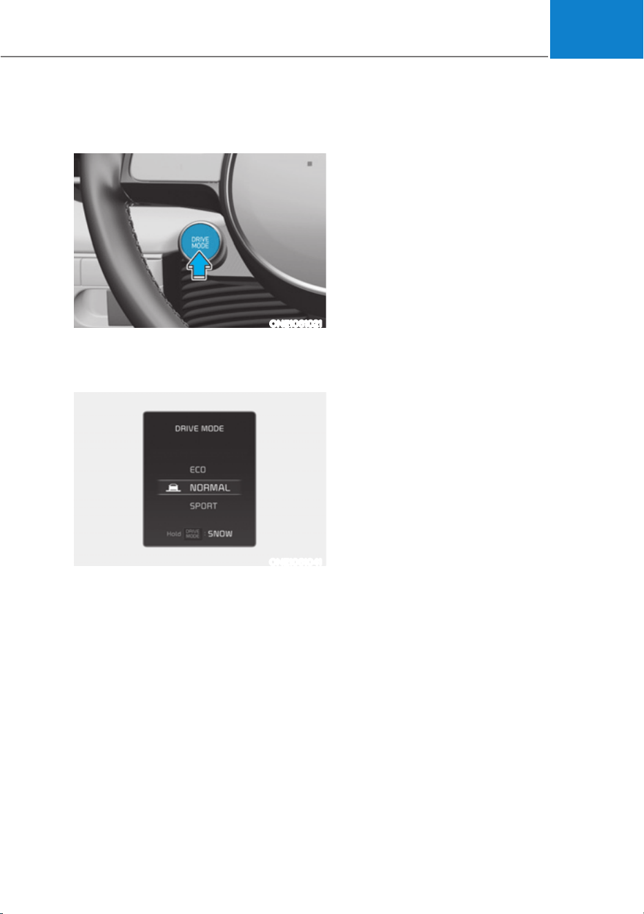
06
6-47
Drive Mode
ONE1061021
Drive mode may be selected according
to the driver's preference or road
condition.
ONE1061041
The mode changes whenever the driver
pushes the DRIVE MODE button.
NORMAL mode
Normal mode is a driving mode used
when driving on general roads, city
center and highways.
ECO mode
ECO mode is a driving mode improving
energy efficiency by controlling motors
and reduction gear.
Electric energy efficiency varies
according to the driver's driving habit
and road condition.
ś When ECO mode is selected, the
ECO indicator will illuminate on the
instrument cluster and the color of the
mood lamp will change.
ś When ECO mode is activated:
- The acceleration response may be
slightly reduced if the accelerator
pedal is depressed moderately.
- The air conditioner performance
may be limited.
The above situations are normal
conditions when ECO mode is
activated to help improve electric
energy efficiency.
Limitations of ECO mode
If the following conditions occur while
ECO mode is operating, the system
operation is limited even though there is
no change in the ECO indicator.
ś When coolant temperature is low:
The system will be limited until motor
performance becomes normal.
ś When driving up a hill:
The system will be limited to gain
power when driving uphill because
motor torque is restricted.
'5,9(02'(,17(*5$7('&21752/6<67(0ǣ:'Ǥ
ǣ,)(48,33('Ǥ

Driving Your Vehicle
6-48
SPORT mode
SPORT mode is a driving mode
improving driving performance by
controlling motors and reduction gear.
In SPORT mode, the electric energy
efficiency may decrease.
ś When SPORT mode is selected, the
SPORT indicator will illuminate on the
instrument cluster and the color of the
mood lamp will change.
ś Whenever the vehicle is restarted,
the drive mode will revert back to
NORMAL mode. If SPORT mode is
desired, re-select SPORT mode.
SNOW mode
SNOW mode provides safe driving on the
snowy roads.
ś Press and hold the drive mode button
to select SNOW mode.
ś When SNOW mode is selected, the
SNOW indicator will illuminate on the
instrument cluster and the color of the
mood lamp will change.
NOTICE
ś Depress the accelerator pedal softly
on the snow and the ice.
ś Keep the distance from the vehicle in
the front.
ś Prevent rapid acceleration,
deceleration and steering control.
Abrupt driving on the snow may
cause the accident.

06
6-49
Drive Mode
ONE1061021
Drive mode may be selected according
to the driver's preference or road
condition.
ONE1061041
The mode changes whenever the driver
pushes the DRIVE mode button.
NORMAL mode
Normal mode is a driving with auto
changing the driving mode(2WD/AWD)
on road condition.
ECO mode
ECO mode is a driving mode vehicles
could change the engagement status
of the motor according to the situation
required. Auto changing the driving
mode(2WD/AWD)helps improve energy
efficiency.
Electric energy efficiency varies
according to the driver's driving habit
and road condition.
ś When ECO mode is selected, the
ECO indicator will illuminate on the
instrument cluster and the color of the
mood lamp will change.
ś When ECO mode is activated:
- The acceleration response may be
slightly reduced if the accelerator
pedal is depressed moderately.
- The air conditioner performance
may be limited.
- The shift pattern of the reduction
gear may change.
The above situations are normal
conditions when ECO mode is
activated to help improve electric
energy efficiency.
'5,9(02'(,17(*5$7('&21752/6<67(0ǣ$:'Ǥ
ǣ,)(48,33('Ǥ

Driving Your Vehicle
6-50
Limitations of ECO mode
If the following conditions occur while
ECO mode is operating, the system
operation is limited even though there is
no change in the ECO indicator.
ś When coolant temperature is low:
The system will be limited until motor
performance becomes normal.
ś When driving up a hill:
The system will be limited to gain
power when driving uphill because
motor torque is restricted.
SPORT mode
SPORT mode is a driving mode
improving driving performance by fixing
AWD system and controlling reduction
gear.
In SPORT mode, the electric energy
efficiency may decrease.
ś When SPORT mode is selected, the
SPORT indicator will illuminate on the
instrument cluster and the color of the
mood lamp will change.
ś Whenever the vehicle is restarted,
the drive mode will revert back to
NORMAL mode. If SPORT mode is
desired, re-select SPORT mode.
SNOW mode
SNOW mode is a driving mode improving
driving performance by changing
the engagement status of the motor
according to the situation required. Auto
changing the driving mode(2WD/AWD)
helps improve driving stability.
ś Press and hold the drive mode button
to select SNOW mode.
ś When SNOW mode is selected, the
SNOW indicator will illuminate on the
instrument cluster and the color of the
mood lamp will change.
ś When SNOW mode is activated, the
driving power is distributed to four
wheels automatically, increasing the
stability of the vehicle.
NOTICE
ś Depress the accelerator pedal softly
on the snow and the ice.
ś Keep the distance from the vehicle in
the front.
ś Prevent rapid acceleration,
deceleration and steering control.
Abrupt driving on the snow may
cause the accident.

06
6-51
Drive Modes Characteristic
The characteristic of each components varies according to which drive mode is
selected.
Drive mode
SNOW NORMAL ECO SPORT
Characteristics
Snow driving
Normal driving
mode
High electric
energy efficiency
mode
Sporty driving
mode
Button activation
Press more
than 1 sec.
Press Press Press
Indicator on the
cluster
SNOW NORMAL ECO SPORT
Climate system
control
NORMAL NORMAL
ECO
(ECO/NORMAL)
*1
NORMAL
Speed Limit - - - -
Regenerative
braking level
0~1 0~3
BRAKE MODE NORMAL
NORMAL/
SPORT
*1
NORMAL
NORMAL/
SPORT
*1
*1 :
It is possible to set the driving condition for each drive mode, at the drive mode setting in
Infotainment system, For more information, refer to the separately supplied manual.
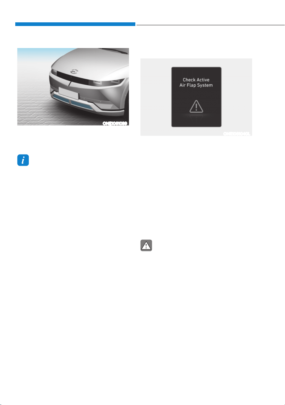
Driving Your Vehicle
6-52
ONE1061039
Active air flap system controls the air flap
below the front bumper to cool the vehicle
parts and improve energy efficiency.
Information
Active air flap system could be activate
regardless of the vehicle condition.(Parking,
driving, charging, etc.)
Malfunction
ONE1061040L
The active air flap system may not operate
normally if the air flap is temporarily
opened due to foreign factors or if the
controller is contaminated by snow or rain,
etc.
When “Check the active air flap system”
is popped up on display, stop the vehicle
in a safe place and check the status of
the air flap.
Start the vehicle after performing the
necessary work like foreign matter
removal and waiting 10 minutes. If
the pop-up remains up, contact an
authorized HYUNDAI dealer.
CAUTION
ś regardless of the pop-up, if the air
flaps aren't in the same position, stop
the vehicle and wait for 10 minutes
and start the vehicle and inspect the
air flap.
ś The active air flap system is actuated
by motors. Do not disturb actuation or
apply force excessively. It may cause
failure.
$&7,9($,5)/$3

06
6-53
Rocking the Vehicle
If it is necessary to rock the vehicle to
free it from snow, sand, or mud, first turn
the steering wheel right and left to clear
the area around your front wheels. Then,
shift back and forth between R (Reverse)
and a forward gear.
Try to avoid spinning the wheels, and do
not race the vehicle.
To prevent reduction gear wear, wait
until the wheels stop spinning before
shifting gears. Release the accelerator
pedal while shifting, and press lightly on
the accelerator pedal while the reduction
gear is in gear. Slowly spinning the
wheels in forward and reverse directions
causes a rocking motion that may free
the vehicle.
WARNING
If the vehicle is stuck and excessive
wheel spin occurs, the temperature
in the tires can increase very quickly.
If the tires become damaged, a tire
blow out or tire explosion can occur.
This condition is dangerous - you and
others may be injured. Do not attempt
this procedure if people or objects are
anywhere near the vehicle.
If you attempt to free the vehicle, the
vehicle can overheat quickly, possibly
causing an motor compartment fire or
other damage. Try to avoid spinning the
wheels as much as possible to prevent
overheating of either the tires or the
motor. DO NOT allow the vehicle to spin
the wheels above 35 mph (56 km/h).
Hazardous Driving Conditions
When hazardous driving elements
are encountered such as water, snow,
ice, mud and sand, take the following
precautions:
ś Drive cautiously and maintain a longer
braking distance.
ś Avoid abrupt braking or steering.
ś When your vehicle is stuck in snow,
mud, or sand, accelerate slowly to
avoid unnecessary wheel spin.
ś Put sand, rock salt, tire chains or other
non-slip materials under the wheels to
provide additional traction while the
vehicle becomes stuck in ice, snow,
or mud.
WARNING
Changing the tire speed suddenly could
cause the tires to skid while driving
on slippery surface. Be careful when
driving on slippery surfaces.
63(&,$/'5,9,1*&21',7,216

Driving Your Vehicle
6-54
Information
The ESC system must be turned OFF
before rocking the vehicle.
NOTICE
If you are still stuck after rocking the
vehicle a few times, have the vehicle
pulled out by a tow vehicle to avoid
motor overheating, possible damage
to the reduction gear, and tire damage.
See “Towing” section in chapter 8.
Smooth Cornering
Avoid braking or gear changing in
corners, especially when roads are wet.
Ideally, corners should always be taken
under gentle acceleration.
Driving at Night
Night driving presents more hazards than
driving in the daylight. Here are some
important tips to remember:
ś Slow down and keep more distance
between you and other vehicles, as it
may be more difficult to see at night,
especially in areas where there may
not be any street lights.
ś Adjust your mirrors to reduce the glare
from other drivers’ headlamps.
ś Keep your headlamps clean and
properly aimed. Dirty or improperly
aimed headlamps will make it much
more difficult to see at night.
ś Avoid staring directly at the
headlamps of oncoming vehicles. You
could be temporarily blinded, and it
will take several seconds for your eyes
to readjust to the darkness.
Driving in the Rain
Rain and wet roads can make driving
dangerous. Here are a few things to
consider when driving in the rain or on
slick pavement:
ś Slow down and allow extra following
distance. A heavy rainfall makes
it harder to see and increases the
distance needed to stop your vehicle.
ś Turn OFF your Cruise Control. (if
equipped)
ś Replace your windshield wiper blades
when they show signs of streaking or
missing areas on the windshield.
ś Be sure your tires have enough tread.
If your tires do not have enough tread,
making a quick stop on wet pavement
can cause a skid and possibly lead to
an accident. See “Tire Tread” section
in chapter 9.
ś Turn on your headlamps to make it
easier for others to see you.
ś Driving too fast through large puddles
can affect your brakes. If you must go
through puddles, try to drive through
them slowly.
ś If you believe your brakes may be wet,
apply them lightly while driving until
normal braking operation returns.

06
6-55
Hydroplaning
If the road is wet enough and you are
going fast enough, your vehicle may
have little or no contact with the road
surface and actually ride on the water.
The best advice is SLOW DOWN when
the road is wet.
The risk of hydroplaning increases as
the depth of tire tread decreases, refer
to “Tire Tread” section in chapter 9.
Driving in Flooded Areas
Avoid driving through flooded areas
unless you are sure the water is no
higher than the bottom of the wheel hub.
Drive through any water slowly. Allow
adequate stopping distance because
brake performance may be reduced.
After driving through water, dry the
brakes by gently applying them several
times while the vehicle is moving slowly.
Highway Driving
Tires
Adjust the tire inflation, as specified.
Under-inflation may overheat or damage
the tires.
Do not install worn-out or damaged tires,
which may reduce traction or fail the
braking operation.
Information
Never over-inflate your tires above the
maximum inflation pressure, as specified
on your tires.
Coolant and high voltage battery
Driving at higher speeds on the highway
consumes more electric energy and is
less efficient than driving at a slower,
more moderate speed. Maintain a
moderate speed in order to conserve
electric energy when driving on the
highway.
Be sure to check both the coolant level
and the electric energy level before
driving.

Driving Your Vehicle
6-56
Reducing the Risk of a Rollover
Your multi-purpose passenger vehicle is
defined as a Sports Utility Vehicle (SUV).
SUV’s have higher ground clearance
and a narrower track to make them
capable of performing in a wide variety
of off-road applications. The specific
design characteristics give them a higher
center of gravity than ordinary vehicles
making them more likely to roll over if
you make abrupt turns. Utility vehicles
have a significantly higher rollover rate
than other types of vehicles. Due to this
risk, driver and passengers are strongly
recommended to buckle their seat belts.
In a rollover crash, an unbelted person
is significantly more likely to die than a
person wearing a seat belt.
There are steps that a driver can make
to reduce the risk of a rollover. If at all
possible, avoid sharp turns or abrupt
maneuvers, do not load your vehicle
with heavy cargo on the roof, and never
modify your vehicle in any way.
WARNING
Utility vehicles have a significantly
higher rollover rate than other types of
vehicles. To prevent rollovers or loss of
control:
ś Take corners at slower speeds than
you would with a passenger vehicle.
ś Avoid sharp turns and abrupt
maneuvers.
ś Do not modify your vehicle in any
way that you would raise the center
of gravity.
ś Keep tires properly inflated.
ś Do not carry heavy cargo on the roof.
WARNING
In a rollover crash, an unbelted person
is significantly more likely to die than a
person wearing a seat belt. Make sure
all passengers are wearing their seat
belts.

06
6-57
The severe weather conditions of winter
quickly wear out tires and cause other
problems. To minimize winter driving
problems, you should take the following
suggestions:
Snow or Icy Conditions
You need to keep sufficient distance
between your vehicle and the vehicle in
front of you.
Apply the brakes gently. Speeding, rapid
acceleration, sudden brake applications,
and sharp turns are potentially very
hazardous practices. Sudden brake
applications on snowy or icy roads may
cause the vehicle to skid.
To drive your vehicle in deep snow, it
may be necessary to install tire chains on
your tires.
Always carry emergency equipment.
Some of the items you may want to carry
include tire chains, tow straps or chains,
a flashlight, emergency flares, sand, a
shovel, jumper cables, a window scraper,
gloves, ground cloth, coveralls, a blanket,
etc.
Summer tires (if equipped)
ś Summer tires are used to maximize
the driving performance on dry roads.
ś If the temperature is below 7°C or
you are driving on snowy or icy roads,
the summer tires lose their brake
performance and traction as the tire
grip weakens significantly.
ś If the temperature is below 7°C or
you are driving on snowy or icy roads,
mount snow tires or all-season tires
of the same size with your vehicle’s
standard tire for safe driving. Both
snow and all-season tires have M+S
markings.
ś When using the M+S tires, use tires
with the same tread produced by the
same manufacturer for safe driving.
ś When driving with the M+S tires with
the lower maximum allowable speed
than that of the vehicle’s standard
summer tire, be careful not to exceed
the speed allowed for the M+S tires.
WINTER DRIVING
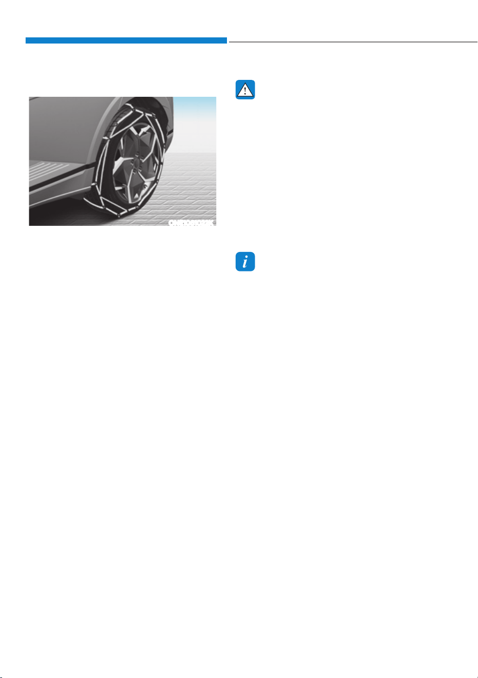
Driving Your Vehicle
6-58
Tire chains (Wire chains)
ONE1061022K
Since the sidewalls of radial tires are
thinner than other types of tires, they
may be damaged by mounting some
types of tire chains on them. Therefore,
the use of snow tires is recommended
instead of tire chains. If tire chains must
be used, use genuine Hyundai parts
and install the tire chain after reviewing
the instructions provided with the tire
chains. Damage to your vehicle caused
by improper tire chain use is not covered
by your vehicle manufacturer’s warranty.
When using tire chains, install tire chains
only on the rear tires.
WARNING
The use of tire chains may adversely
affect vehicle handling:
ś Drive less than 20 mph (30 km/h)
or the chain manufacturer’s
recommended speed limit,
whichever is lower.
ś Drive carefully and avoid bumps,
holes, sharp turns, and other road
hazards, which may cause the
vehicle to bounce.
ś Avoid sharp turns or locked wheel
braking.
Information
ś Install tire chains only in pairs and on
the rear tires. It should be noted that
installing tire chains on the tires will
provide a greater driving force, but will
not prevent side skids.
ś Do not install studded tires without
first checking local and municipal
regulations for possible restrictions
against their use.
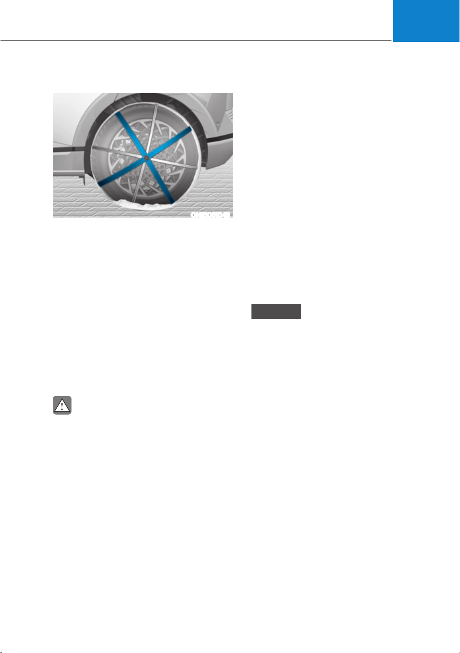
06
6-59
Tire chains (Auto sock)
ONE1061045
Since the sidewalls of radial tires are
thinner, they can be damaged by
mounting some types of snow chains on
them. Therefore, the use of snow tires is
recommended instead of snow chains.
Do not mount tire chains on vehicle
equipped with aluminum wheels;
snow chains may cause damage to the
wheels. If snow chains must be used, use
AutoSock (fabric snow chain). Damage
to your vehicle caused by improper snow
chain use is not covered by your vehicle
manufacturer’s warranty.
When using tire chains, install tire chains
only on the rear tires.
CAUTION
Always check chain installation
for proper mounting after driving
approximately 0.3 to 0.6 miles (0.5 to 1
km) to ensure safe mounting. Retighten
or remount the chains if they are loose.
Chain Installation
When installing tire chains, follow the
manufacturer’s instructions and mount
them as tightly possible. Drive slowly
(less than 20 mph (30 km/h)) with
chains installed. If you hear the chains
contacting the body or chassis, stop and
tighten them. If they still make contact,
slow down until the noise stops. Remove
the tire chains as soon as you begin
driving on cleared roads.
When mounting snow chains, park the
vehicle on level ground away from traffic.
Turn on the vehicle Hazard Warning
Flasher and place a triangular emergency
warning device behind the vehicle (if
available). Always place the vehicle in P
(Park), apply the parking brake and turn
off the vehicle before installing snow
chains.
NOTICE
When using tire chains:
ś Wrong size chains or improperly
installed chains can damage your
vehicle’s brake lines, suspension,
body and wheels.
ś Use SAE “S” class or wire chains.
ś If you hear noise caused by chains
contacting the body, retighten the
chain to prevent contact with the
vehicle body.
ś To prevent body damage, retighten
the chains after driving 0.3~0.6 miles
(0.5~1.0 km).
ś Do not use tire chains on vehicles
equipped with aluminum wheels. If
unavoidable, use a wire type chain.
ś Install tire chains that meet the
specifications of each tire size to
prevent damage your vehicle.
- 19 in. tires use wire chains less than
0.47in. (12 mm).
- 20 in. tires use AutoSock (fabric
snow chain).

Driving Your Vehicle
6-60
Winter Precautions
Check battery and cables
Winter temperatures affect battery
performance. Inspect the battery and
cables, as specified in chapter 9. The
battery charging level can be checked
by an authorized HYUNDAI dealer or in a
service station.
To prevent locks from freezing
To prevent the locks from being frozen,
spray approved de-icing fluid or glycerin
into key holes. When a lock opening is
already covered with ice, spray approved
de-icing fluid over the ice to remove it.
When an internal part of a lock freezes,
try to thaw it with a heated key. Carefully
use the heated key to avoid an injury.
Use approved window washer anti-
freeze solution in system
To prevent the window washer from
being frozen, add authorized window
washer anti-freeze solution, as specified
on the window washer container.
Window washer anti-freeze solution is
available from an authorized HYUNDAI
dealer, and most vehicle accessory
outlets. Do not use coolant or other types
of anti-freeze solution, to prevent any
damage to the vehicle paint.
Do not let your parking brake freeze
Under some conditions your parking
brake can freeze in the engaged position.
This is most likely to happen when there
is an accumulation of snow or ice around
or near the rear brakes or if the brakes
are wet. When there is the risk that your
parking brake may freeze, temporarily
apply it with the gear in P (Park). Also,
block the rear wheels in advance, so the
vehicle may not roll. Then, release the
parking brake.
Do not let ice and snow accumulate
underneath
Under some conditions, snow and ice
can build up under the fenders and
interfere with the steering. When driving
in such conditions during the severe
winter, you should check underneath
the vehicle on a regular basis, to ensure
that the front wheels and the steering
components is unblocked.
Carry emergency equipment
In accordance with weather conditions,
you should carry appropriate emergency
equipment, while driving. Some of the
items you may want to carry include tire
chains, tow straps or chains, flashlight,
emergency flares, sand, shovel, jumper
cables, window scraper, gloves, ground
cloth, coveralls, blanket, etc.
Do not place objects or materials in the
motor compartment
Putting objects or materials in the motor
compartment may cause an motor
failure. Such damage will not be covered
by the manufacturer’s warranty.

06
6-61
Two labels on your driver’s door sill
show how much weight your vehicle
was designed to carry: the Tire and
Loading Information Label and the
Certification Label.
Before loading your vehicle,
familiarize yourself with the
following terms for determining
your vehicle’s weight ratings, from
the vehicle’s specifications and the
Certification Label:
Base Curb Weight
This is the weight of the vehicle
including a full tank of fuel and
all standard equipment. It does
not include passengers, cargo, or
optional equipment.
Vehicle Curb Weight
This is the weight of your new
vehicle when you picked it up from
your dealer plus any aftermarket
equipment.
Cargo Weight
This figure includes all weight added
to the Base Curb Weight, including
cargo and optional equipment.
GAW (Gross Axle Weight)
This is the total weight placed on
each axle (front and rear) - including
vehicle curb weight and all payload.
GAWR (Gross Axle Weight Rating)
This is the maximum allowable
weight that can be carried by a single
axle (front or rear). These numbers
are shown on the Certification Label.
The total load on each axle must
never exceed its GAWR.
GVW (Gross Vehicle Weight)
This is the Base Curb Weight
plus actual Cargo Weight plus
passengers.
GVWR (Gross Vehicle Weight
Rating)
This is the maximum allowable
weight of the fully loaded vehicle
(including all options, equipment,
passengers and cargo). The GVWR
is shown on the Certification Label
located on the driver’s door sill.
9(+,&/(/2$'/,0,7
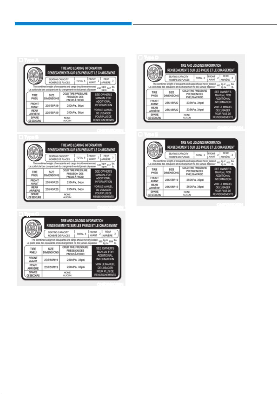
Driving Your Vehicle
6-62
The Loading Information Label
Type A
ONE1061056N
Type B
ONE1061057N
Type C
ONE1061058N
Type D
ONE1061061N
Type E
ONE1061062N
The label located on the driver’s door
sill gives the original tire size, cold
tire pressures recommended for your
vehicle, the number of people that
can be in your vehicle and vehicle
capacity weight.

06
6-63
Vehicle capacity weight
5 persons (Standard type) :
947 lbs. (430 kg)
5 persons (Extended type) :
859 lbs. (390 kg)
Vehicle capacity weight is the
maximum combined weight of
occupants and cargo. If your
vehicle is equipped with a trailer,
the combined weight includes the
tongue load.
Seating capacity
Total : 5 persons (Front seat : 2
persons, Rear seat : 3 persons)
Seating capacity is the maximum
number of occupants including
a driver, your vehicle may carry.
However, the seating capacity may
be reduced based upon the weight
of all of the occupants, and the
weight of the cargo being carried or
towed. Do not overload the vehicle
as there is a limit to the total weight,
or load limit including occupants and
cargo, the vehicle can carry.
Towing capacity
With brake system :
2,000 lbs (907 kg)
Without brake system :
1,653 lbs (750 kg)
Towing capacity is the maximum
trailer weight including its cargo
weight, your vehicle can tow.
Cargo capacity
The cargo capacity of your vehicle
will increase or decrease depending
on the weight and the number of
occupants and the tongue load,
if your vehicle is equipped with a
trailer.

Driving Your Vehicle
6-64
Steps for determining correct load
limit
1. Locate the statement "The
combined weight of occupants
and cargo should never exceed
XXX kg or XXX lbs." on your
vehicle's placard.
2. Determine the combined weight
of the driver and passengers that
will be riding in your vehicle.
3. Subtract the combined weight of
the driver and passengers from
XXX kg or XXX lbs.
4. The resulting figure equals
the available amount of cargo
and luggage load capacity. For
example, if the "XXX" amount
equals 1400 lbs. and there will
be five 150 lb passengers in your
vehicle, the amount of available
cargo and luggage load capacity
is 650 lbs. (1400 - 750 (5 x 150) =
650 lbs.)
5. Determine the combined weight
of luggage and cargo being
loaded on the vehicle. That
weight may not safely exceed the
available cargo and luggage load
capacity calculated in Step 4.
6. If your vehicle will be towing a
trailer, load from your trailer will
be transferred to your vehicle.
Consult this manual to determine
how this reduces the available
cargo and luggage load capacity
of your vehicle.
WARNING
Do not overload the vehicle as
there is a limit to the total weight,
or load limit, including occupants
and cargo, the vehicle can carry.
Overloading can shorten the life
of the vehicle. If the GVWR or the
GAWR is exceeded, parts on the
vehicle can break, and it can change
the handling of your vehicle. These
could cause you to lose control and
result in an accident.
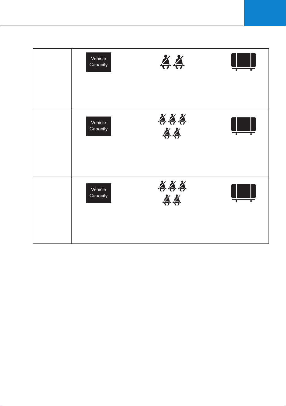
06
6-65
Example 1
ŧ +
Maximum
Load
(1400 lbs.)
(635 kg)
Passenger Weight
(150 lbs. × 2 = 300
lbs.)
(68 kg × 2 = 136 kg)
Cargo Weight
(1100 lbs.)
(499 kg)
Example 2
ŧ +
Maximum
Load
(1400 lbs.)
(635 kg)
Passenger Weight
(150 lbs. × 5 = 750
lbs.)
(68 kg × 5 = 340 kg)
Cargo Weight
(650 lbs.)
(295 kg)
Example 3
ŧ +
Maximum
Load
(1400 lbs.)
(635 kg)
Passenger Weight
(172 lbs. × 5 = 860
lbs.)
(78 kg × 5 = 390 kg)
Cargo Weight
(540 lbs.)
(245 kg)
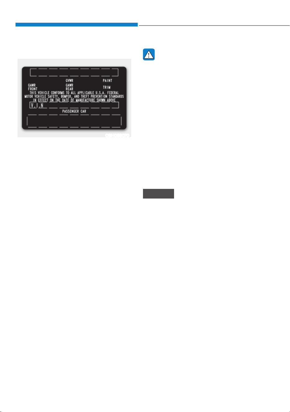
Driving Your Vehicle
6-66
Certification label
OBH059070
The certification label is located on
the driver's door sill at the center
pillar and shows the maximum
allowable weight of the fully loaded
vehicle. This is called the GVWR
(Gross Vehicle Weight Rating). The
GVWR includes the weight of the
vehicle, all occupants, fuel and
cargo.
This label also tells you the maximum
weight that can be supported by the
front and rear axles, called Gross
Axle Weight Rating (GAWR).
The total weight of the vehicle,
including all occupants, accessories,
cargo, and trailer tongue load must
not exceed the Gross Vehicle Weight
Rating (GVWR) or the Gross Axle
Weight Rating (GAWR). To find out
the actual loads on your front and
rear axles, you need to go to a weigh
station and weigh your vehicle. Be
sure to spread out your load equally
on both sides of the centerline.
WARNING
Overloading
ś Never exceed the GVWR for your
vehicle, the GAWR for either the
front or rear axle and vehicle
capacity weight. Exceeding these
ratings can affect your vehicle's
handling and braking ability, and
cause an accident.
ś Do not overload your vehicle.
Overloading your vehicle can
cause heat buildup in your
vehicle's tires and possible
tire failure, increased stopping
distances and poor vehicle
handling-all of which may result
in a crash.
NOTICE
Overloading your vehicle may cause
damage. Repairs would not be
covered by your warranty. Do not
overload your vehicle.

06
6-67
WARNING
If you carry items inside your
vehicle (for example, suitcases,
tools, packages, or anything else),
they are moving as fast as the
vehicle. If you have to stop or turn
quickly, or if there is a crash, the
items will keep going and can cause
an injury if they strike the driver or a
passenger.
ś Put items in the cargo area of
your vehicle. Try to spread the
weight evenly.
ś Do not stack items, like suitcases,
inside the vehicle above the tops
of the seats.
ś Do not leave an unsecured child
restraint in your vehicle.
ś When you carry something inside
the vehicle, secure it.

Driving Your Vehicle
6-68
If you are considering to tow with your
vehicle, you should first your country’s
legal requirements. As laws vary the
requirements for towing trailers, cars, or
other types of vehicles or apparatus may
differ. Ask an authorized HYUNDAI dealer
for further details before towing.
Remember that trailering is different
than just driving your vehicle by itself.
Trailering means changes in handling,
durability, and electric energy economy.
Successful, safe trailering requires
correct equipment, and it has to be used
properly. Damage to your vehicle caused
by improper trailer towing is not covered
by your vehicle manufacturer’s warranty.
This section contains many time-tested,
important trailering tips and safety
rules. Many of these are important for
your safety and that of your passengers.
Please read this section carefully before
you pull a trailer.
WARNING
Take the following precautions:
ś If you don’t use the correct
equipment and/or drive improperly,
you can lose control of the vehicle
when you are pulling a trailer. For
example, if the trailer is too heavy,
the braking performance may be
reduced. You and your passengers
could be seriously or fatally injured.
Pull a trailer only if you have followed
all the steps in this section.
ś Before towing, make sure the
total trailer weight, GCW (Gross
Combination Weight), GVW (Gross
Vehicle Weight), GAW (Gross Axle
Weight) and trailer tongue load are
all within the limits.
If You Decide to Pull a Trailer
Here are some important points if you
decide to pull a trailer:
ś Consider using a sway control. You
can ask a trailer hitch dealer about
sway control.
ś Do not do any towing with your
vehicle during its first 1,200 miles
(2,000 km) in order to allow the
vehicle to properly break in. Failure to
heed this caution may result in serious
motor damage.
ś When towing a trailer, consult an
authorized HYUNDAI dealer for
further information on additional
requirements such as towing kit etc.
ś Always drive your vehicle at a
moderate speed (less than 60 mph
(100 km/h)) or posted towing speed
limit.
ś On a long uphill grade, do not exceed
45 mph (70 km/h) or the posted
towing speed limit, whichever is
lower.
ś Carefully observe the weight and load
limits provided in the following pages.
TRAILER TOWING
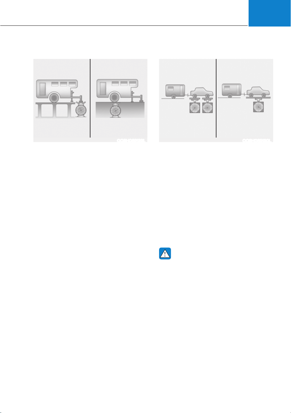
06
6-69
Trailer weight
Tongue Load Total Trailer Weight
OOSH069129L
What is the maximum safe weight of a
trailer? It should never weigh more than
the maximum trailer weight with trailer
brakes. But even that can be too heavy.
It depends on how you plan to use your
trailer. For example, speed, altitude,
road grades, outside temperature and
how often your vehicle is used to pull a
trailer are all important. The ideal trailer
weight can also depend on any special
equipment that you have on your vehicle.
Tongue load
Gross Axle Weight Gross Vehicle Weight
OOSH069130L
The tongue load is an important weight
to measure because it affects the
total Gross Vehicle Weight (GVW) of
your vehicle. The trailer tongue should
weigh a maximum of 10% of the total
loaded trailer weight, within the limits
of the maximum trailer tongue load
permissible.
After you’ve loaded your trailer,
weigh the trailer and then the tongue,
separately, to see if the weights are
proper. If they aren’t, you may be able
to correct them simply by moving some
items around in the trailer.
WARNING
Take the following precautions:
ś Never load a trailer with more weight
in the rear than in the front. The front
should be loaded with approximately
60% of the total trailer load; the rear
should be loaded with approximately
40% of the total trailer load.
ś Never exceed the maximum weight
limits of the trailer or trailer towing
equipment. Improper loading can
result in damage to your vehicle and/
or personal injury. Check weights
and loading at a commercial scale or
highway patrol office equipped with
scales.

Driving Your Vehicle
6-70
Reference weight and distance when towing a trailer
ltem Standard type Extended type
Maximum trailer weight
lbs. (kg)
With brake
system
- 2000 (907)
Without brake
system
- 1653 (750)
Maximum permissible static vertical load on
the coupling device
lbs. (kg)
- 220 (100)
Recommended distance from rear wheel
center to coupling point
inch (mm)
- 34 (867)
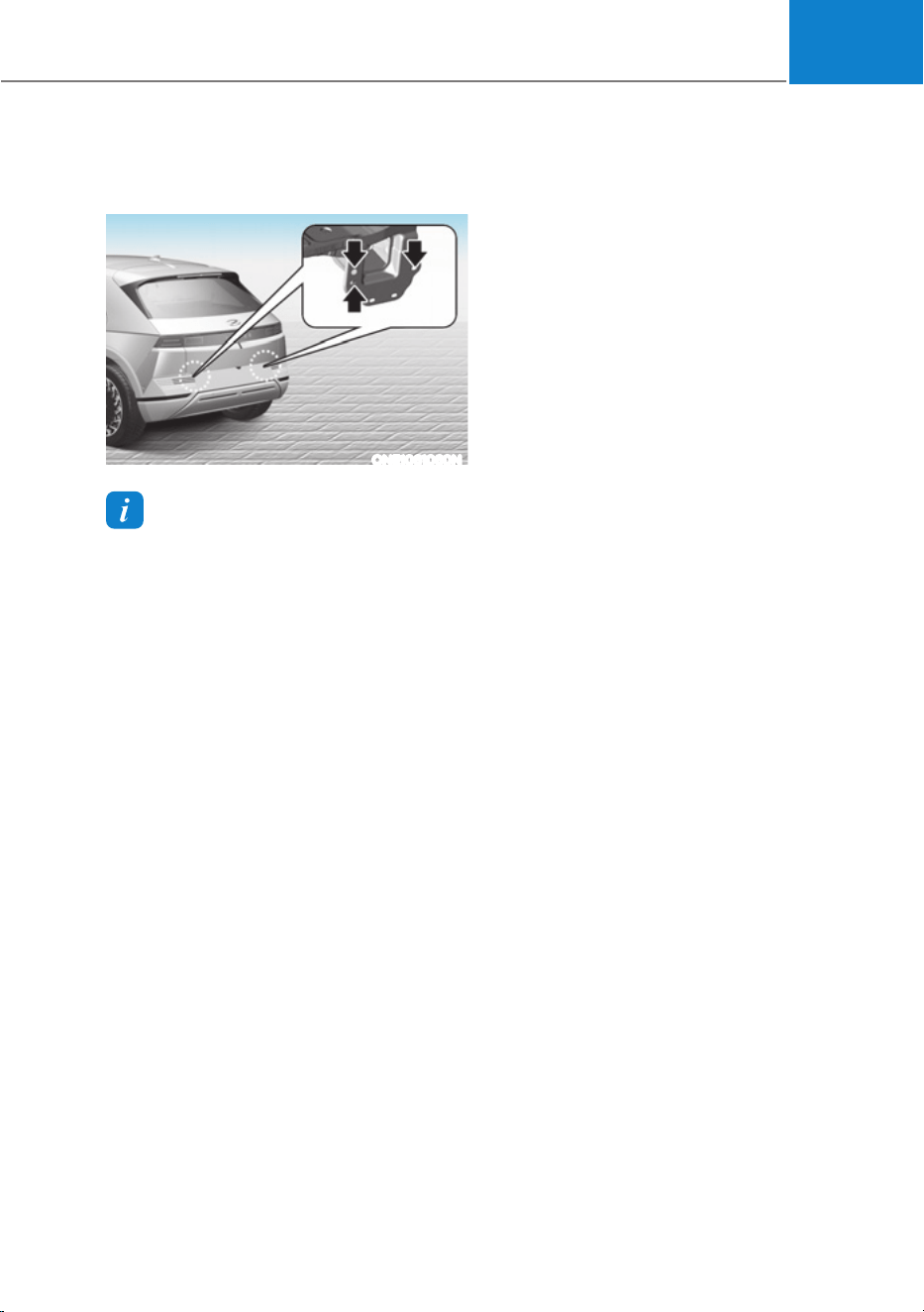
06
6-71
Trailer Towing Equipment
Hitches
ONE1061060N
Information
The mounting hole for hitches are located
on both sides of the underbody behind the
rear tires.
It’s important to have the correct hitch
equipment. Crosswinds, large trucks
going by, and rough roads are a few
reasons why you’ll need the right hitch.
Here are some rules to follow:
ś Do you have to make any holes in
the body of your vehicle when you
install a trailer hitch? If you do, then
be sure to seal the holes later when
you remove the hitch. If you don’t seal
them, dirt and water can get into your
vehicle.
ś The bumpers on your vehicle are not
intended for hitches. Do not attach
rental hitches or other bumper-type
hitches to them. Use only a frame-
mounted hitch that does not attach to
the bumper.
ś Any part of the rear number plate or
lighting devices of the vehicle must
not be obscured by the mechanical
coupling device.
If the rear number plate and/or
lighting devices can be obscured
partially by any part of the mechanical
coupling device, mechanical coupling
devices that can not be easily
removed or repositioned without use
of any tools, except an easily operated
(for example, an effort not exceeding
20Nm) release key which is supplied
by the manufacturer of the coupling
device, are not permitted for use.
Please note that the mechanical
coupling device that is fitted and
not in use must always be removed
or repositioned if the rear number
plate and/or rear lighting devices
are obscured by any part of the
mechanical coupling device.
ś A HYUNDAI Vehicle trailer hitch
accessory is available at an authorized
HYUNDAI dealer.

Driving Your Vehicle
6-72
Safety chains
You should always attach chains between
your vehicle and your trailer.
Instructions about safety chains may
be provided by the hitch manufacturer
or trailer manufacturer. Follow the
manufacturer’s recommendation for
attaching safety chains. Always leave just
enough slack so you can turn with your
trailer. And, never allow safety chains to
drag on the ground.
Trailer brakes
If your trailer is equipped with a braking
system, make sure it conforms to
your country’s regulations and that
it is properly installed and operating
correctly.
If your trailer weighs more than the
maximum trailer weight without trailer
brakes loaded, then it needs its own
brakes and they must be adequate. Be
sure to read and follow the instructions
for the trailer brakes so you’ll be able
to install, adjust and maintain them
properly. Be sure not to modify your
vehicle’s brake system.
WARNING
Do not use a trailer with its own brakes
unless you are absolutely certain that
you have properly set up the brake
system. This is not a task for amateurs.
Use an experienced, competent trailer
shop for this work.
Driving with a Trailer
Towing a trailer requires a certain
amount of experience. Before setting
out for the open road, you must get to
know your trailer. Acquaint yourself with
the feel of handling and braking with the
added weight of the trailer. And always
keep in mind that the vehicle you are
driving is now longer and not nearly as
responsive as your vehicle is by itself.
Before you start, check the trailer hitch
and platform, safety chains, electrical
connector(s), lights, tires and brakes.
During your trip, occasionally check
to be sure that the load is secure, and
that the lights and trailer brakes are still
working.
Information
When the ambient temperature is lower
than 32°F (0°C) and the remaining high
voltage battery is low, the power of the
vehicle with a trailer can be dropped,
causing a trouble in acceleration or drop
of the speed when driving hills.
When driving with a trailer, be sure to
charge the high voltage battery more than
50% if the ambient temperature is lower
than 32°F (0°C).

06
6-73
Distance
Stay at least twice as far behind the
vehicle ahead as you would when driving
your vehicle without a trailer. This can
help you avoid situations that require
heavy braking and sudden turns.
Passing
You will need more passing distance up
ahead when you’re towing a trailer. And,
because of the increased vehicle length,
you’ll need to go much farther beyond
the passed vehicle before you can return
to your lane.
Backing up
Hold the bottom of the steering wheel
with one hand. Then, to move the trailer
to the left, move your hand to the left. To
move the trailer to the right, move your
hand to the right. Always back up slowly
and, if possible, have someone guide
you.
Making turns
When you’re turning with a trailer, make
wider turns than normal. Do this so your
trailer won’t strike soft shoulders, curbs,
road signs, trees, or other objects. Avoid
jerky or sudden maneuvers. Signal well in
advance.
Turn signals
When you tow a trailer, your vehicle has
to have a different turn signal flasher and
extra wiring. The green arrows on your
instrument panel will flash whenever you
signal a turn or lane change. Properly
connected, the trailer lights will also flash
to alert other drivers you’re about to turn,
change lanes, or stop.
When towing a trailer, the green arrows
on your instrument panel will flash for
turns even if the bulbs on the trailer
are burned out. Thus, you may think
drivers behind you are seeing your
signals when, in fact, they are not. It’s
important to check occasionally to be
sure the trailer bulbs are still working.
You must also check the lights every time
you disconnect and then reconnect the
wires.
WARNING
Do not connect a trailer lighting system
directly to your vehicle’s lighting
system. Use an approved trailer wiring
harness. Failure to do so could result
in damage to the vehicle electrical
system and/or personal injury. Consult
an authorized HYUNDAI dealer for
assistance.

Driving Your Vehicle
6-74
Driving on hills
Reduce speed before you start down a
long or steep downgrade.
On a long uphill grade, reduce your
speed to around 45 mph (70 km/h)
to reduce the possibility of motor
overheating.
NOTICE
To prevent motor overheating:
When towing a trailer, your vehicle
speed may be much slower than the
general flow of traffic, especially when
climbing an uphill grade. Use the right
hand lane when towing a trailer on an
uphill grade. Choose your vehicle speed
according to the maximum posted
speed limit for vehicles with trailers, the
steepness of the grade, and your trailer
weight.
Parking on hills
Generally, if you have a trailer attached
to your vehicle, you should not park your
vehicle on a hill.
However, if you ever have to park your
trailer on a hill, here’s how to do it:
1. Pull the vehicle into the parking space.
Turn the steering wheel in the
direction of the curb (right if headed
down hill, left if headed up hill).
2. Shift the gear to P (Park).
3. Set the parking brake and shut off the
vehicle.
4. Place wheel chocks under the trailer
wheels on the down hill side of the
wheels.
5. Start the vehicle, hold the brakes, shift
to neutral, release the parking brake
and slowly release the brakes until the
trailer chocks absorb the load.
6. Reapply the brakes and parking
brakes.
7. Shift the gear to P (Park) when the
vehicle is parked on a uphill grade and
in R (Reverse) on a downhill.
8. Shut off the vehicle and release the
vehicle brakes but leave the parking
brake set.

06
6-75
WARNING
To prevent serious or fatal injury:
ś Do not get out of the vehicle without
the parking brake firmly set. If you
have left the vehicle running, the
vehicle can move suddenly. You and
others could be seriously or fatally
injured.
ś Do not apply the accelerator pedal to
hold the vehicle on an uphill.
Driving the vehicle after it has been
parked on a hill
1. With the gear in P (Park), apply your
brakes and hold the brake pedal down
while you:
śStart your vehicle;
śShift into gear; and
śRelease the parking brake.
2. Slowly remove your foot from the
brake pedal.
3. Drive slowly until the trailer is clear of
the chocks.
4. Stop and have someone pick up and
store the chocks.
Maintenance when Towing a
Trailer
Your vehicle will need service more
often when you regularly pull a trailer.
Important items to pay particular
attention to include reduction gear fluid,
axle lubricant and cooling system fluid.
Brake condition is another important
item to frequently check. If you’re
trailering, it’s a good idea to review these
items before you start your trip. Don’t
forget to also maintain your trailer and
hitch. Follow the maintenance schedule
that accompanied your trailer and check
it periodically. Preferably, conduct the
check at the start of each day’s driving.
Most importantly, all hitch nuts and bolts
should be tight.
NOTICE
To prevent vehicle damage:
ś Due to higher load during trailer
usage, overheating might occur on
hot days or during uphill driving.
ś When towing check reduction gear
fluid more frequently.

Driving Your Vehicle
6-76
Two labels on your driver’s door sill show
how much weight your vehicle was
designed to carry: the Tire and Loading
Information Label and the Certification
Label.
Before loading your vehicle, familiarize
yourself with the following terms for
determining your vehicle’s weight
ratings, from the vehicle’s specifications
and the Certification Label:
Base Curb Weight
This is the weight of the vehicle
including high voltage battery and
all standard equipment. It does not
include passengers, cargo, or optional
equipment.
Vehicle Curb Weight
This is the weight of your new vehicle
when you picked it up from your dealer
plus any aftermarket equipment.
Cargo Weight
This figure includes all weight added to
the Base Curb Weight, including cargo
and optional equipment.
GAW (Gross Axle Weight)
This is the total weight placed on each
axle (front and rear) - including vehicle
curb weight and all payload.
GAWR (Gross Axle Weight Rating)
This is the maximum allowable weight
that can be carried by a single axle (front
or rear). These numbers are shown on
the Certification Label. The total load on
each axle must never exceed its GAWR.
GVW (Gross Vehicle Weight)
This is the Base Curb Weight plus actual
Cargo Weight plus passengers.
GVWR (Gross Vehicle Weight Rating)
This is the maximum allowable weight
of the fully loaded vehicle (including
all options, equipment, passengers
and cargo). The GVWR is shown on the
Certification Label located on the driver’s
door sill.
Overloading
WARNING
The Gross Axle Weight Rating (GAWR)
and the Gross Vehicle Weight Rating
(GVWR) for your vehicle are on the
Certification Label attached to the
driver’s (or front passenger’s) door.
Exceeding these ratings can cause an
accident or vehicle damage. You can
calculate the weight of your load by
weighing the items (and people) before
putting them in the vehicle. Be careful
not to overload your vehicle.
9(+,&/(:(,*+7

7
Driving Safety
Forward Collision–Avoidance Assist (FCA) ............................................................. 7-2
Lane Keeping Assist (LKA) ...................................................................................... 7-26
Blind-Spot Collision-Avoidance Assist (BCA) ........................................................ 7-32
Safe Exit Assist (SEA) ..............................................................................................7-46
Manual Speed Limit Assist (MSLA) ......................................................................... 7-53
Intelligent Speed Limit Assist (ISLA) .......................................................................7-56
Driver Attention Warning (DAW) ............................................................................ 7-62
Blind-Spot View Monitor (BVM) .............................................................................7-68
Driving Convenience
Smart Cruise Control (SCC)..................................................................................... 7-70
Navigation-based Smart Cruise Control (NSCC) ..................................................7-89
Lane Following Assist (LFA) .................................................................................... 7-97
Highway Driving Assist (HDA) ............................................................................... 7-101
Parking Safety
Rear View Monitor (RVM) ........................................................................................7-113
Surround View Monitor (SVM) .............................................................................. 7-116
Rear Cross-Traffic Collision-Avoidance Assist (RCCA) ........................................ 7-122
Reverse Parking Distance Warning (PDW) ...........................................................7-134
Forward/Reverse Parking Distance Warning (PDW) ............................................ 7-137
Reverse Parking Collision-Avoidance Assist (PCA) ..............................................7-142
Parking convenience
Remote Smart Parking Assist (RSPA) ....................................................................7-150
Declaration of Conformity ............................................................................................ 7-175
7. Driver Assistance System
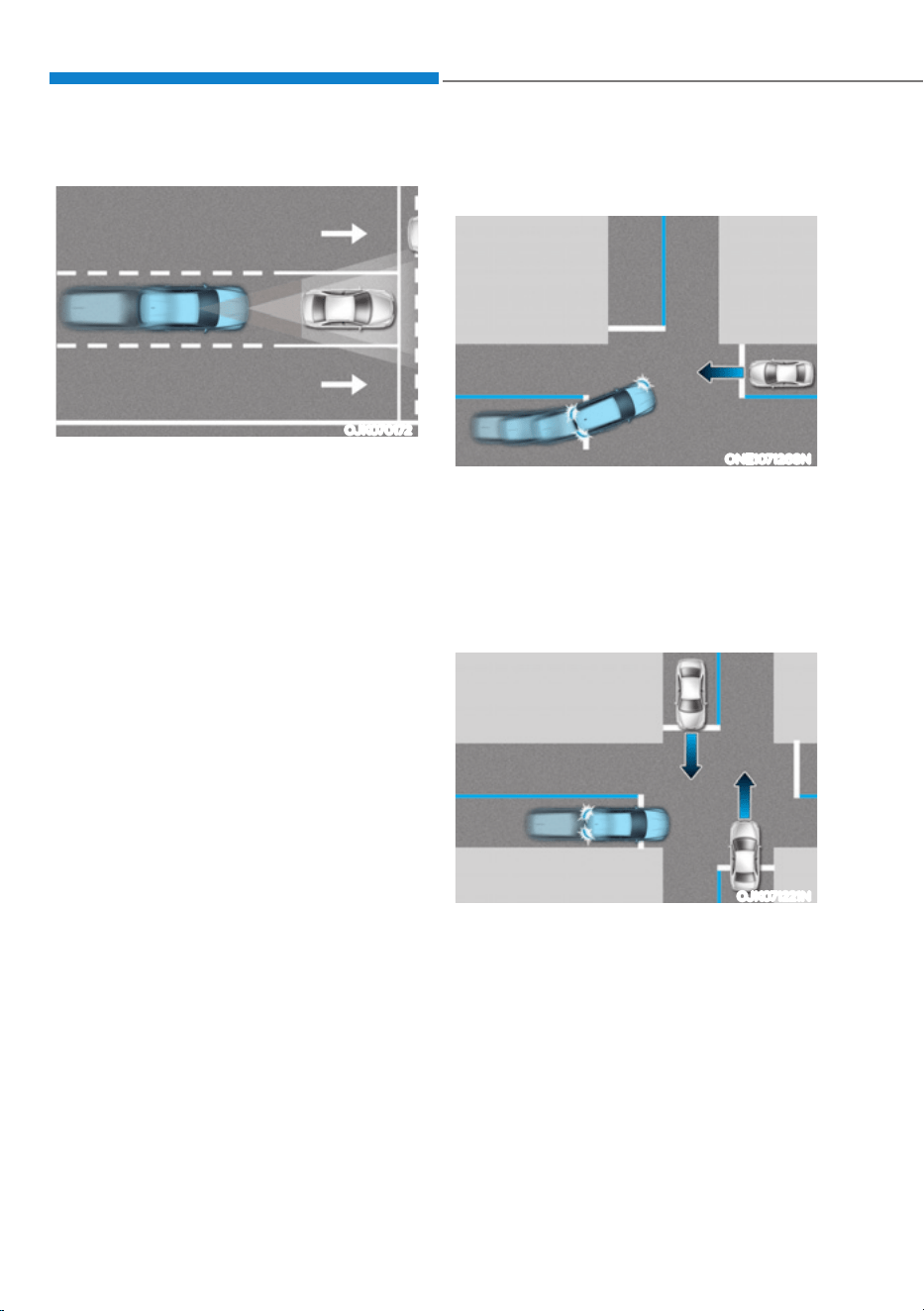
Driver Assistance System
7-2
OJK070172
Forward Collision-Avoidance Assist is
designed to help detect and monitor the
vehicle ahead or help detect a pedestrian
or cyclist in the roadway and warn the
driver that a collision is imminent with
a warning message and an audible
warning, apply emergency braking.
In addition, if equipped with front corner
radars, when driving at high speeds,
Forward Collision-Avoidance Assist helps
detect vehicles in front and adjacent
lanes. If a collision is imminent when
changing lanes, Forward Collision-
Avoidance Assist will apply emergency
braking to help prevent a collision.
Junction Turning function
ONE1071268N
Junction Turning function helps avoid
a collision with an oncoming vehicle in
an adjacent lane when turning left at
a crossroad with the turn signal on by
applying emergency braking.
Junction Crossing function (if
equipped)
OJK071221N
Junction Crossing function helps avoid
a collision with oncoming vehicles on
the left or right side when crossing an
intersection by applying emergency
braking.
)25:$5'&2//,6,21Ǚ$92,'$1&($66,67ǣ)&$Ǥǣ,)
(48,33('Ǥ
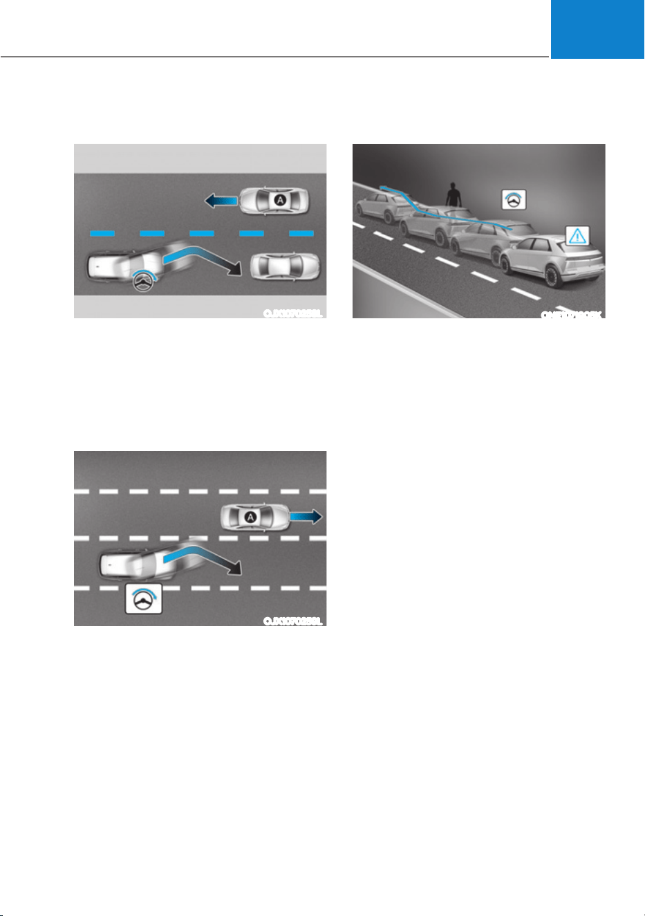
07
7-3
Lane-Change Oncoming function (if
equipped)
OJX1070258L
[A] : Oncoming vehicle
Lane-Change Oncoming function helps
avoid a collision with an oncoming
vehicle when changing lanes by assisting
the driver’s steering.
Lane-Change Side function (if
equipped)
OJX1070259L
[A] : Front-side vehicle
Lane-Change Side function helps avoid
a collision with the vehicle ahead in
the next lane when changing lanes by
assisting the driver’s steering.
Evasive Steering Assist function (if
equipped)
ONE1071005K
ś Driver steering assist
Evasive Steering Assist function
helps avoid a collision with a vehicle,
pedestrian or cyclist ahead in the
same lane. When a risk of collision
is detected, Evasive Steering Assist
function will warn the driver and if the
driver steers to avoid collision it will
assist the driver’s steering.
ś Evasive steering assist
Evasive Steering Assist function helps
avoid a collision with a pedestrian or
cyclist ahead in the same lane. When
a risk of collision is detected, Evasive
Steering Assist function will warn the
driver and if there is space to avoid
collision in the lane, it will assist the
driver’s steering.
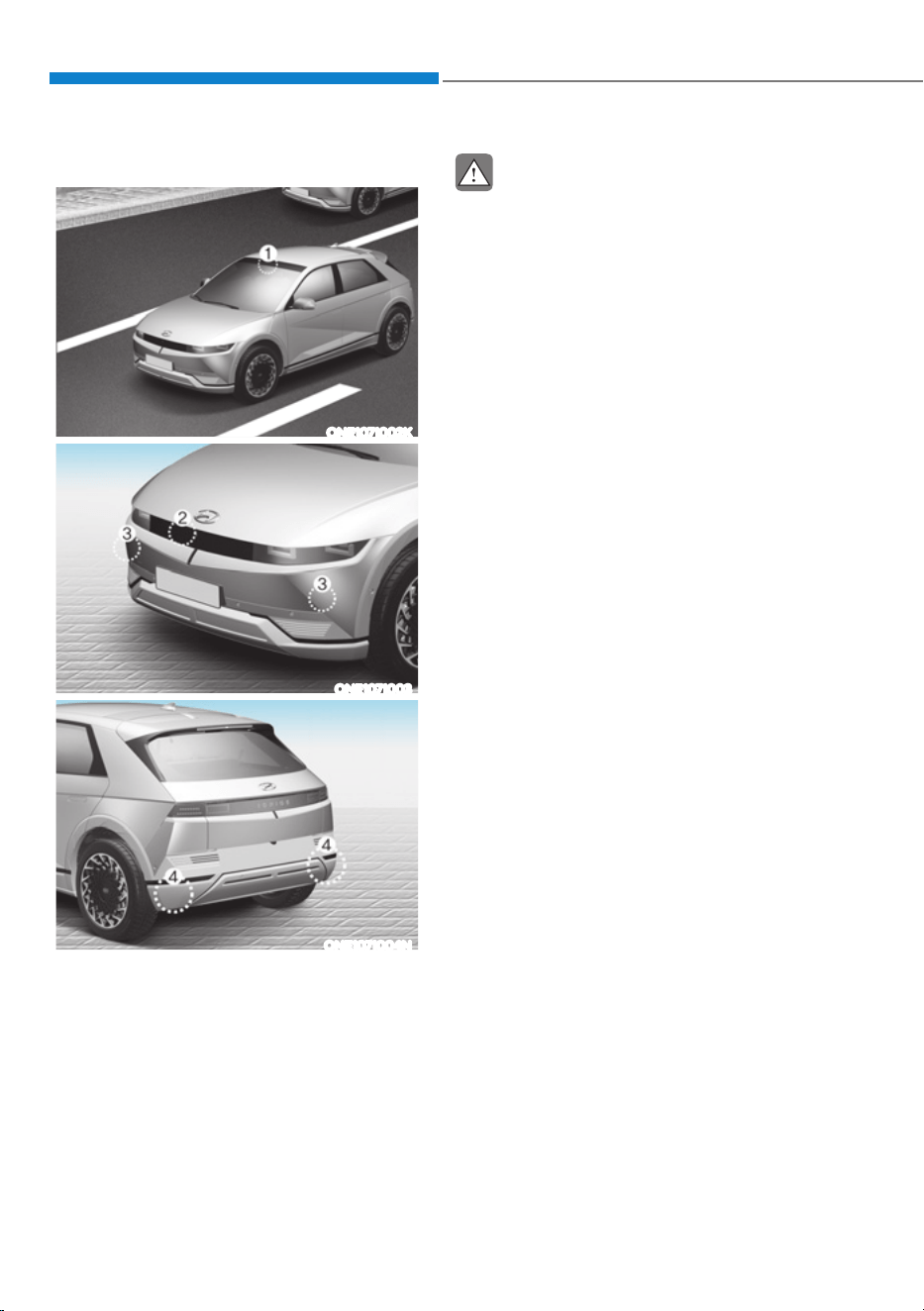
Driver Assistance System
7-4
Detecting sensor
ONE1071002K
ONE1071003
ONE1071004N
[1]: Front view camera, [2]: Front radar,
[3]: Front corner radar (if equipped),
[4]: Rear corner radar (if equipped)
Refer to the picture above for the
detailed location of the detecting
sensors.
CAUTION
Take the following precautions to
maintain optimal performance of the
detecting sensor:
ś Never disassemble the detecting
sensor or sensor assembly, or cause
any damage to it.
ś If the detecting sensors have
been replaced or repaired, have
the vehicle be inspected by an
authorized HYUNDAI dealer.
ś Never install any accessories or
stickers on the front windshield, or
tint the front windshield.
ś Pay extreme caution to keep the
front view camera dry.
ś Never place any reflective objects
(for example, white paper, mirror)
over the dashboard.
ś Do not place any objects near the
front windshield or install any
accessories on the front windshield.
It can affect the performance of the
defogging and defrosting function
of the climate control system, which
may prevent the Driver Assistance
systems from operating
ś Do not place objects or mount
structures near the windshield.
When operating the air conditioner,
moisture and defrost performance
may be poor, and driver assistance
functions may not work.
ś Do not apply license plate frame or
objects, such as a bumper sticker,
film or a bumper guard, near the
front radar cover.
ś Always keep the front radar and
cover clean and free of dirt and
debris.
Use only a soft cloth to wash the
vehicle. Do not spray pressurized
water directly on the sensor or
sensor cover.

07
7-5
ś If unnecessary force has been
applied to the radar or around the
radar, Forward Collision-Avoidance
Assist may not properly operate
even though a warning message
does not appear on the cluster.
Have the vehicle be inspected by an
authorized HYUNDAI dealer.
ś Use only genuine parts to repair or
replace a damaged front radar cover.
Do not apply paint to the front radar
cover.
ś Vehicles equipped with front corner
radar and/or rear corner radar
- Do not apply license plate frame or
objects, such as a bumper sticker,
film or a bumper guard, near the
front corner radar or rear corner
radar.
- The function may not work
properly when the bumper has
been replaced, or the surroundings
of the front corner radar or rear
corner radar has been damaged or
paint has been applied.
- If a trailer, carrier, etc., is installed,
it may adversely affect the
performance of the rear corner
radar or Forward Collision-
Avoidance Assist may not operate
properly.
Forward Collision-Avoidance
Assist Settings
Setting features
ONE1071206L
Forward Safety
With the vehicle on, select or deselect
œ'ULYHU$VVLVWDQFHƟ)RUZDUG6DIHW\ŔIURP
the Settings menu to set whether or not
to use each function.
- If ‘Active Assist’ is selected, Forward
Collision-Avoidance Assist will warn
the driver with a warning message
and an audible warning depending on
the collision risk levels. Braking assist
or steering assist (if equipped) will be
applied depending on the collision
risk level.
- If ‘Warning Only’ is selected, Forward
Collision-Avoidance Assist will warn
the driver with a warning message
and an audible warning depending
on the collision risk levels. Braking
and steering (if equipped) will not be
assisted. The driver must apply the
brake pedal or steer the vehicle if
necessary.
- If ‘Off’ is selected, Forward Collision-
Avoidance Assist will turn off. The
warning light illuminates on the
cluster.
The driver can monitor Forward
Collision-Avoidance Assist On/Off
status from the Settings menu. If the
warning light remains on when Forward
Collision-Avoidance Assist is on, have the
vehicle be inspected by an authorized
HYUNDAI dealer.
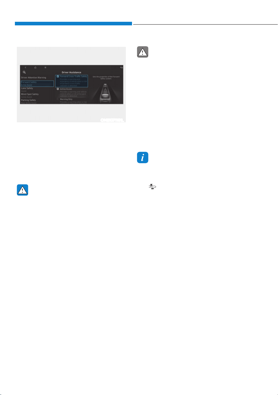
Driver Assistance System
7-6
ONE1071181L
Forward Cross-Traffic Safety (if
equipped)
With the vehicle on, select ‘Driver
$VVLVWDQFHƟ)RUZDUG6DIHW\Ɵ)RUZDUG
Cross-Traffic Safety’ from the Settings
menu to turn on Junction Crossing
function and deselect to turn off the
function.
WARNING
When the vehicle is restarted, Forward
Collision-Avoidance Assist will always
turn on. However, if ‘Off’ is selected, the
driver should always be aware of the
surroundings and drive safely.
CAUTION
ś If ‘Warning Only’ is selected, braking
and steering (if equipped) is not
assisted.
ś The settings for Forward Safety
include ‘Basic function’, ‘Junction
Turning’, ‘Lane-Change Oncoming’,
‘Lane-Change Side’ and ‘Evasive
Steering Assist’ (if equipped).
ś If Forward Safety is set to ‘Off’,
Junction Crossing function will
not operate even when ‘Forward
Cross-Traffic Safety’ (if equipped) is
selected.
Information
Forward Collision-Avoidance Assist
will turn off when ESC is turned off by
pressing and holding the ESC OFF button.
The
warning light will illuminate on
the cluster.

07
7-7
ONE1071282N
Warning Timing
With the vehicle on, select ‘Driver
$VVLVWDQFHƟ:DUQLQJ7LPLQJŔIURPWKH
Settings menu to change the initial
warning activation time for Forward
Collision-Avoidance Assist.
When the vehicle is first delivered,
Warning Timing is set to ‘Normal’. If you
change the Warning Timing, the Warning
Timing of other Driver Assistance
systems may change.
ONE1071202N
Warning Volume
With the vehicle on, select ‘Driver
$VVLVWDQFHƟ:DUQLQJ9ROXPHŔIURPWKH
Settings menu to change the Warning
Volume to ‘High’, ‘Medium’ or ‘Low’ for
Forward Collision-Avoidance Assist.
If you change the warning volume,
the Warning Volume of other Driver
Assistance systems may change.
CAUTION
ś The setting of the Warning Timing
and Warning Volume applies to
all functions of Forward Collision-
Avoidance Assist.
ś Even though ‘Normal’ is selected for
Warning Timing, if the front vehicle
suddenly stops, the warning may
seem late.
ś Select ‘Late’ for Warning Timing
when traffic is light and when driving
speed is slow.
Information
If the vehicle is restarted, Warning Timing
and Warning Volume will maintain the
last setting.
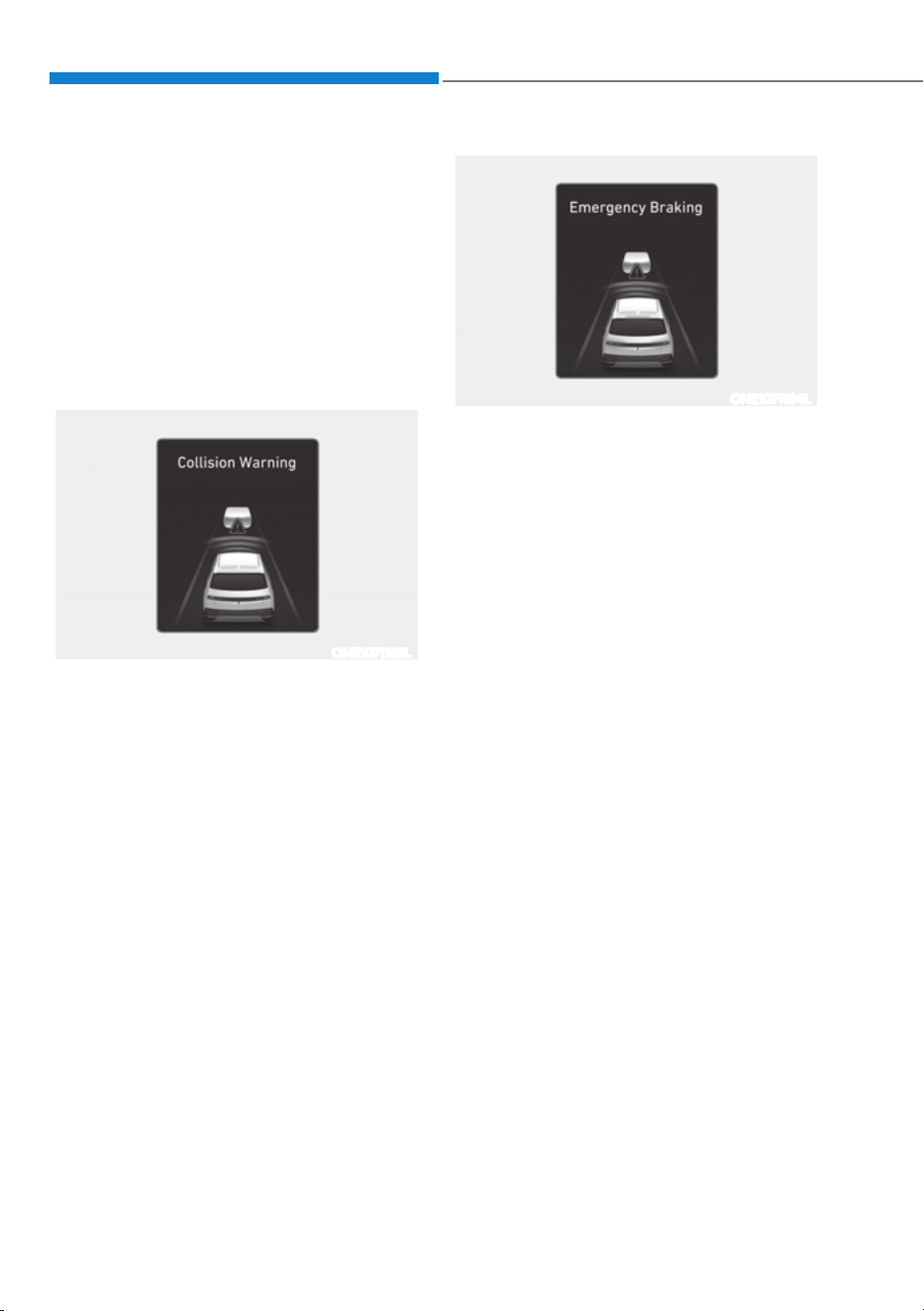
Driver Assistance System
7-8
Forward Collision-Avoidance
Assist Operation
Basic function
Warning and control
The basic function for Forward Collision-
Avoidance Assist is to warn and help
control the vehicle depending on the
collision risk level: ‘Collision Warning’,
‘Emergency Braking’ and ‘Stopping
vehicle and ending brake control’.
ONE1071183L
Collision Warning
ś To warn the driver of a collision, the
‘Collision Warning’ warning message
will appear on the cluster, an audible
warning will sound.
ś If a vehicle is detected in front,
the function will operate when
your vehicle speed is between
approximately 6
- 124 mph (10 - 200
km/h).
ś If a pedestrian or cyclist is detected
in front, the function will operate
when your vehicle speed is between
approximately 6
- 53 mph (10 - 85
km/h).
ś If ‘Active Assist’ is selected, braking
may be assisted.
ONE1071184L
Emergency Braking
ś To warn the driver that emergency
braking will be assisted, the
‘Emergency Braking’ warning
message will appear on the cluster, an
audible warning will sound.
ś If a vehicle is detected in front,
the function will operate when
your vehicle speed is between
approximately 6
- 47 mph (10 - 75
km/h).
ś If Forward Collision- Avoidance
Assist judges that avoiding a collision
is difficult even by changing the
driving lane, the function will operate
when your vehicle speed is between
approximately 6
- 62 mph (10 - 100
km/h) (if equipped with front corner
radar).
The function operation range may
decrease due to the front traffic
condition or the surroundings of the
vehicle.
ś If a pedestrian or cyclist is detected
in front, the function will operate
when your vehicle speed is between
approximately 6
- 40 mph (10 - 65
km/h).
ś In emergency braking situation,
braking is assisted with strong braking
power by the function to help prevent
collision with the vehicle, pedestrian
or cyclist ahead.
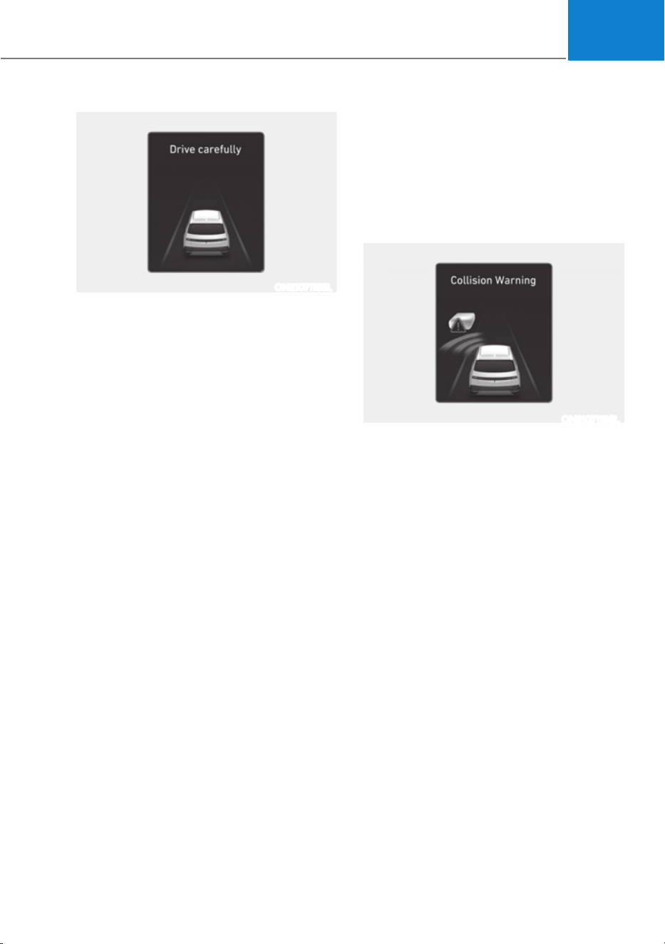
07
7-9
ONE1071185L
Stopping vehicle and ending brake control
ś When the vehicle is stopped due
to emergency braking, the ‘Drive
carefully’ warning message will
appear on the cluster.
For your safety, the driver should
depress the brake pedal immediately
and check the surroundings.
ś Brake control will end after the vehicle
is stopped by emergency braking for
approximately 2 seconds.
Junction Turning function
Warning and control
Junction Turning function will warn and
control the vehicle depending on the
collision risk level: ‘Collision Warning’,
‘Emergency Braking’ and ‘Stopping
vehicle and ending brake control’
ONE1071186L
Collision Warning
ś To warn the driver of a collision, the
‘Collision Warning’ warning message
will appear on the cluster, an audible
warning will sound.
ś The function will operate when
your vehicle speed is between
approximately 6
- 19 mph (10 - 30
km/h) and the oncoming vehicle
speed is between approximately 19
-
44 mph (30 - 70 km/h).
ś If ‘Active Assist’ is selected, braking
may be assisted.
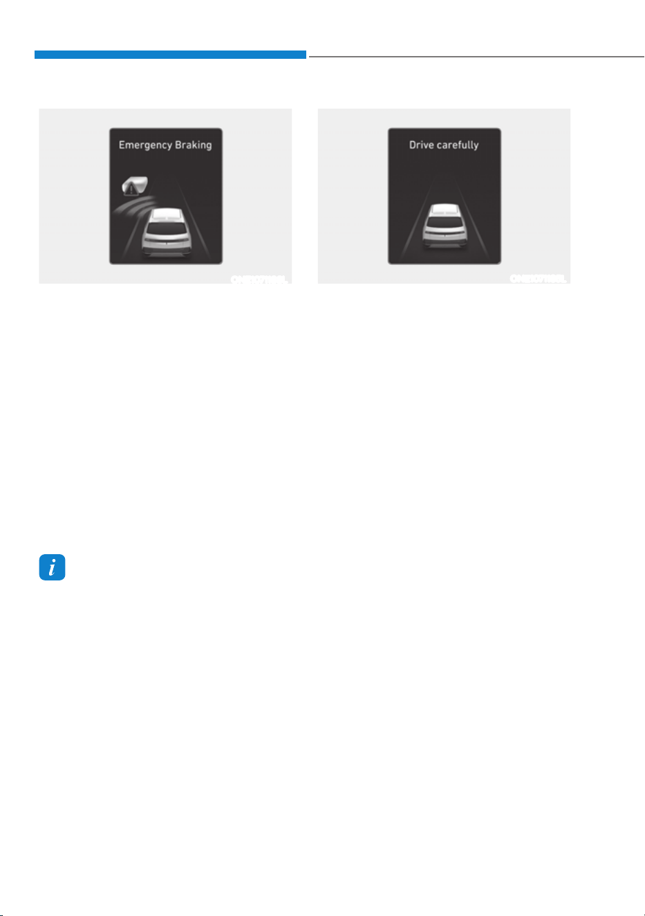
Driver Assistance System
7-10
ONE1071188L
Emergency Braking
ś To warn the driver that emergency
braking will be assisted, the
‘Emergency Braking’ warning
message will appear on the cluster, an
audible warning will sound.
ś The function will operate when
your vehicle speed is between
approximately 6
- 19 mph (10 - 30
km/h) and the oncoming vehicle
speed is between approximately 19
-
44 mph (30 - 70 km/h).
ś In emergency braking situation,
braking is assisted with strong braking
power by the function to help prevent
collision with the oncoming vehicle.
Information
If the driver's seat is on the left side,
Junction Turning function will operate
only when the driver turns left. If the
driver's seat position is on right side, the
function will operate only when you turn
right.
ONE1071185L
Stopping vehicle and ending brake control
ś When the vehicle is stopped due
to emergency braking, the ‘Drive
carefully’ warning message will
appear on the cluster.
For your safety, the driver should
depress the brake pedal immediately
and check the surroundings.
ś Brake control will end after the vehicle
is stopped by emergency braking for
approximately 2 seconds.
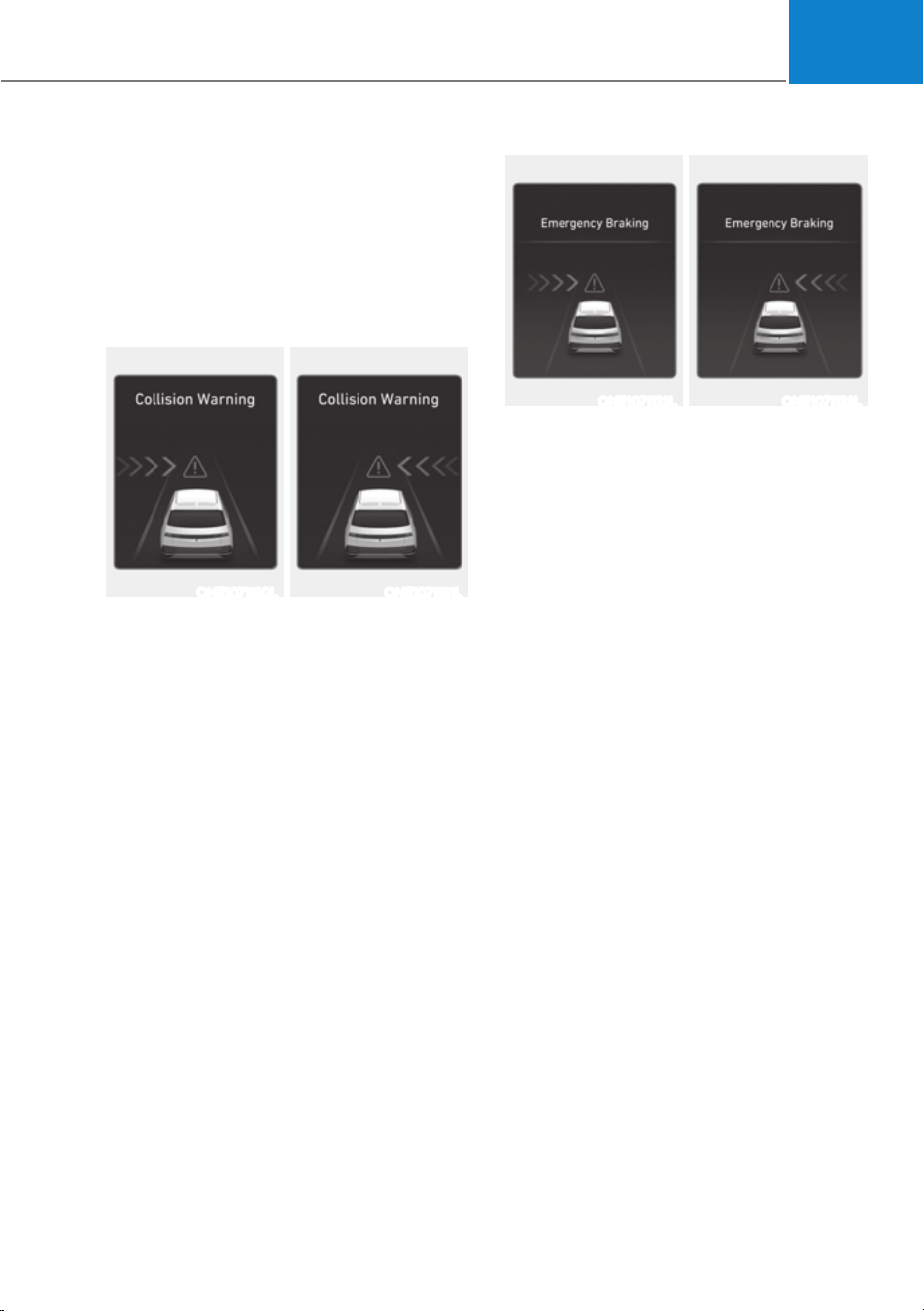
07
7-11
Junction Crossing function (if
equipped)
Warning and control
Junction Crossing function will warn
and control the vehicle depending on
collision risk level: ‘Collision Warning’,
‘Emergency Braking’ and ‘Stopping
vehicle and ending brake control’
ONE1071190L ONE1071191L
Collision Warning
ś To warn the driver of a collision, the
‘Collision Warning’ warning message
will appear on the cluster, an audible
warning will sound.
ś The function will operate when
your vehicle speed is between
approximately 6
- 19 mph (10 - 30
km/h) and the crossing vehicle speed
is between approximately 6
- 37 mph
(10
- 60 km/h).
ś If ‘Active Assist’ and 'Forward Cross-
Traffic Safety' are selected, braking
may be assisted.
ONE1071122L ONE1071123L
Emergency Braking
ś To warn the driver that emergency
braking will be assisted, the
‘Emergency Braking’ warning
message will appear on the cluster, an
audible warning will sound.
ś The function will operate when
your vehicle speed is between
approximately 6
- 19 mph (10 - 30
km/h) and the crossing vehicle speed
is between approximately 6
- 12 mph
(10
- 20 km/h).
ś In emergency braking situation,
braking is assisted with strong braking
power by the function to help prevent
collision with the crossing vehicle.
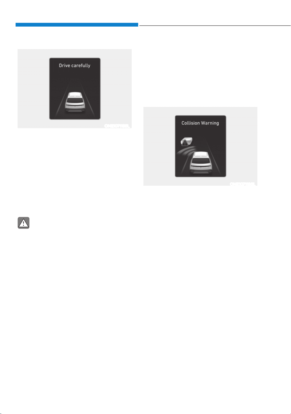
Driver Assistance System
7-12
ONE1071185L
Stopping vehicle and ending brake control
ś When the vehicle is stopped due
to emergency braking, the ‘Drive
carefully’ warning message will
appear on the cluster.
For your safety, the driver should
depress the brake pedal immediately
and check the surroundings.
ś Brake control will end after the vehicle
is stopped by emergency braking for
approximately 2 seconds.
CAUTION
If the collision angle with the crossing
vehicle is beyond a certain range,
Junction Crossing function warning and
control may be late or may not operate.
Lane-Change Oncoming function (if
equipped)
Warning and control
Lane-Change Oncoming function will
warn and control the vehicle depending
on collision risk level: ‘Collision Warning’
and ‘Emergency Steering’
ONE1071186L
Collision Warning
ś To warn the driver of a collision, the
‘Collision Warning’ warning message
will appear on the cluster, an audible
warning will sound.
ś The function will operate when
your vehicle speed is between
approximately 25
- 90 mph (40 - 145
km/h) and the oncoming vehicle
speed is approximately above 6 mph
(10 km/h) and the relative speed with
your vehicle is approximately below
124 mph (200 km/h).
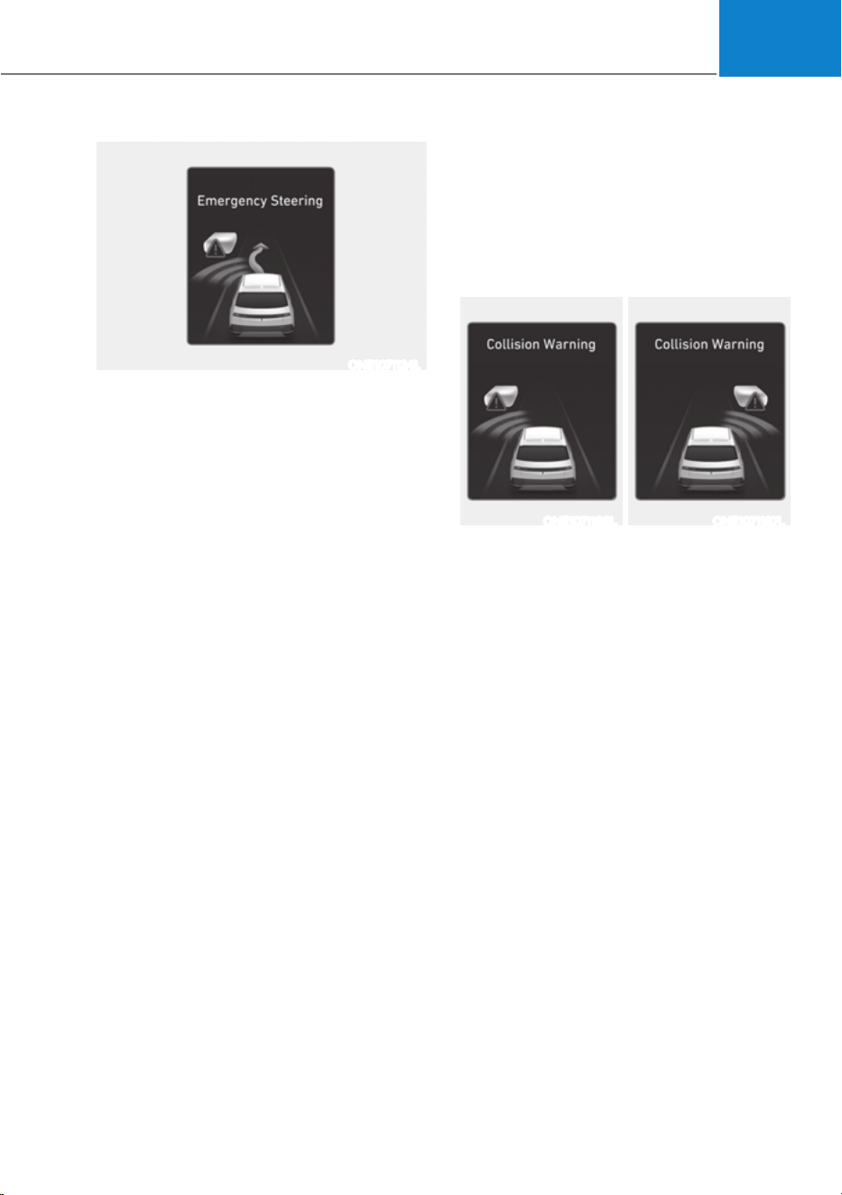
07
7-13
ONE1071124L
Emergency Steering
ś To warn the driver that emergency
steering will be assisted, the
‘Emergency Steering’ warning
message will appear on the cluster, an
audible warning will sound.
ś The function will operate when
your vehicle speed is between
approximately 25
- 90 mph (40 - 145
km/h) and the oncoming vehicle
speed is approximately above 6 mph
(10 km/h) and the relative speed with
your vehicle is approximately below
124 mph (200 km/h).
ś In emergency steering situation,
steering is assisted by the function
to help prevent collision with the
oncoming vehicle.
Lane-Change Side function (if
equipped)
Warning and control
Lane-Change Side function will warn
and control the vehicle depending on
collision risk level: ‘Collision Warning’
and ‘Emergency Steering’
ONE1071186L ONE1071187L
Collision Warning
ś To warn the driver of a collision, the
‘Collision Warning’ warning message
will appear on the cluster, an audible
warning will sound.
ś The function will operate when
your vehicle speed is between
approximately 25
- 90 mph (40 - 145
km/h).
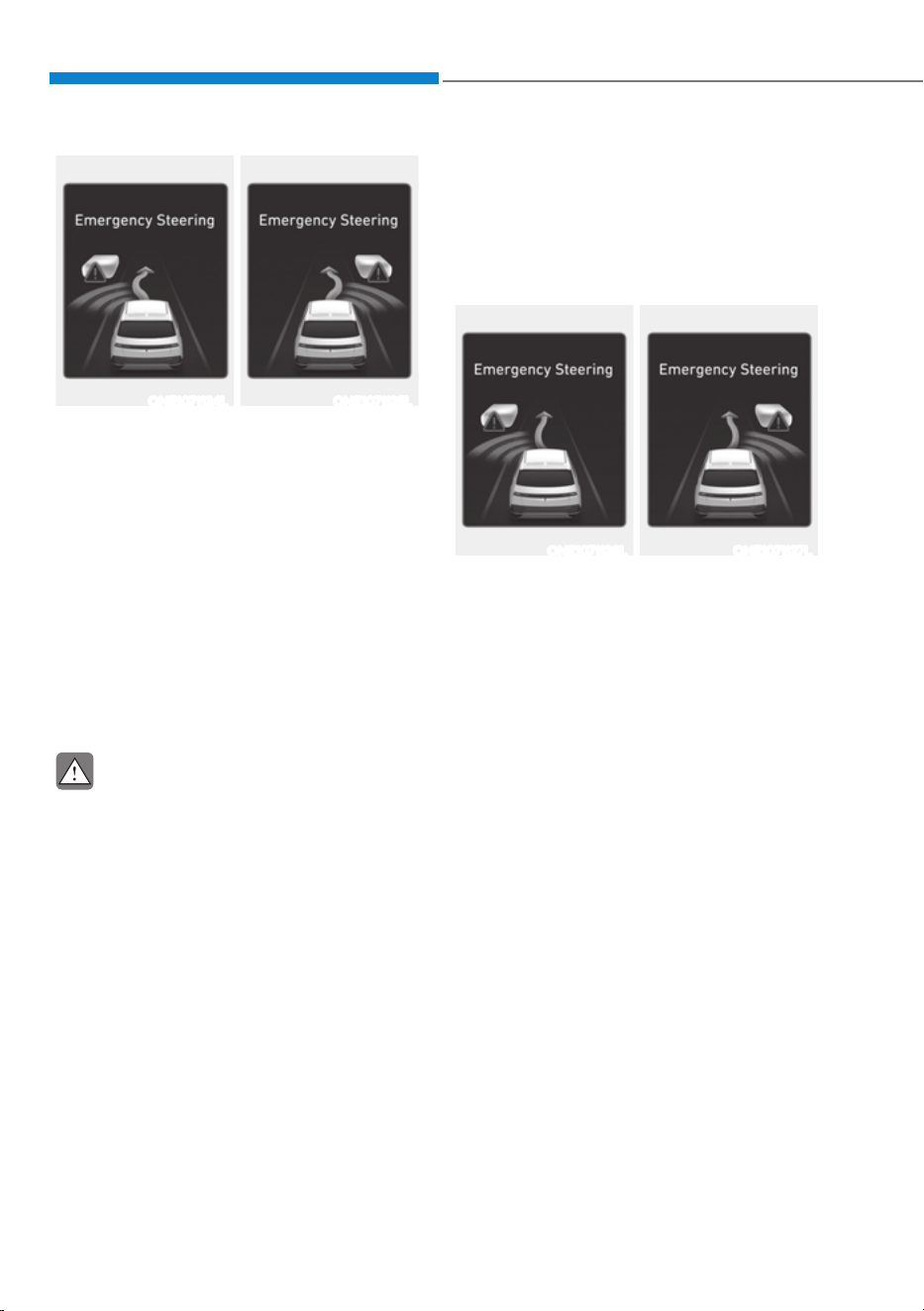
Driver Assistance System
7-14
ONE1071124L ONE1071125L
Emergency Steering
ś To warn the driver that emergency
steering will be assisted, the
‘Emergency Steering’ warning
message will appear on the cluster, an
audible warning will sound.
ś The function will operate when
your vehicle speed is between
approximately 25
- 90 mph (40 - 145
km/h).
ś In emergency steering situation,
steering is assisted by the function to
help prevent collision with the front-
side vehicle.
CAUTION
Lane-Change Side function does not
operate if the vehicle speed of the
oncoming vehicle from the front side is
0 mph (0 km/h).
Evasive Steering Assist function (if
equipped)
Warning and control
Evasive Steering Assist function will warn
and control the vehicle with ‘Emergency
steering’.
ONE1071126L ONE1071127L
Emergency Steering (Driver steering
assist)
ś To warn the driver that emergency
steering will be assisted, the
‘Emergency Steering’ message will
appear on the cluster, an audible
warning will sound.
ś The function will operate when
your vehicle speed is between
approximately 25
- 53 mph (40 - 85
km/h).
ś If there is a risk of collision with a
vehicle, pedestrian and cyclist in
front, the steering will be assisted to
help prevent collision when the driver
steers the vehicle to avoid collision.

07
7-15
ONE1071126L ONE1071127L
Emergency Steering (Evasive steering
assist)
ś To warn the driver that emergency
steering will be assisted, the
‘Emergency Steering’ message will
appear on the cluster, an audible
warning will sound.
ś The function will operate when
your vehicle speed is between
approximately 40
- 47 mph (65 - 75
km/h).
ś If there is high risk of collision with a
pedestrian and cyclist in front, and the
vehicle speed to operate emergency
braking is within the operation range,
the steering will be assisted to help
prevent collision when there is space
to avoid collision in the driving lane.
CAUTION
ś The steering wheel may turn
automatically when emergency
steering is operating.
ś Emergency steering will
automatically cancel when risk
factors disappear. If necessary, the
driver must steer the vehicle.
ś Emergency steering may not operate
or may cancel during operation if
the steering wheel is held tight or
steered in the opposite direction.
ś When steering is assisted to avoid
collision with a vehicle, pedestrian
and cyclist, Evasive steering assist
will be canceled if collisions with
other objects (vehicles, pedestrians,
or cyclists) are expected.
ś Evasive steering assist may not
operate if space to avoid collision in
the driving lane is insufficient.
Information
For more details on warning messages,
refer to Collision Warning in “Basic
Function”.
Information
The images or colors may be displayed
differently depending on the specifications
of the instrument panel or theme.

Driver Assistance System
7-16
WARNING
Take the following precautions when
using Forward Collision-Avoidance
Assist:
ś For your safety, change the Settings
after parking the vehicle at a safe
location.
ś With ‘Active Assist’ or ‘Warning Only’
selected, when ESC is turned off by
pressing and holding the ESC OFF
button, Forward Collision-Avoidance
Assist will turn off automatically.
In this case, Forward Collision-
Avoidance Assist cannot be set
from the Settings menu and the
warning light will illuminate on the
cluster which is normal. If ESC is
turned on by pressing the ESC OFF
button, Forward Collision-Avoidance
Assist will maintain the last setting.
ś Forward Collision-Avoidance Assist
does not operate in all situations or
cannot avoid all collisions.
ś The driver should hold the
responsibility to control the vehicle.
Do not solely depend on Forward
Collision-Avoidance Assist. Rather,
maintain a safe braking distance, and
if necessary, depress the brake pedal
to reduce driving speed or to stop
the vehicle.
ś Never deliberately operate Forward
Collision-Avoidance Assist on people,
objects, etc. It may cause serious
injury or death.
ś Forward Collision-Avoidance
Assist may not operate if the driver
depresses the brake pedal to avoid
collision.
ś Depending on the road and driving
conditions, Forward Collision-
Avoidance Assist may warn the driver
late or may not warn the driver.
ś During Forward Collision-Avoidance
Assist operation, the vehicle may
stop suddenly injuring passengers
and shifting loose objects. Always
have the seat belt on and keep loose
objects secured.
ś If any other system’s warning
message is displayed or audible
warning is generated, Forward
Collision-Avoidance Assist warning
message may not be displayed
and audible warning may not be
generated.
ś You may not hear the warning sound
of Forward Collision-Avoidance
Assist if the surrounding is noisy.
ś Forward Collision-Avoidance
Assist may turn off or may not
operate properly or may operate
unnecessarily depending on the road
conditions and the surroundings.
WARNING
ś Even if there is a problem with
Forward Collision-Avoidance
Assist, the vehicle’s basic braking
performance will operate properly.
ś During emergency braking, braking
control by Forward Collision-
Avoidance Assist will automatically
cancel when the driver excessively
depresses the accelerator pedal or
sharply steers the vehicle.
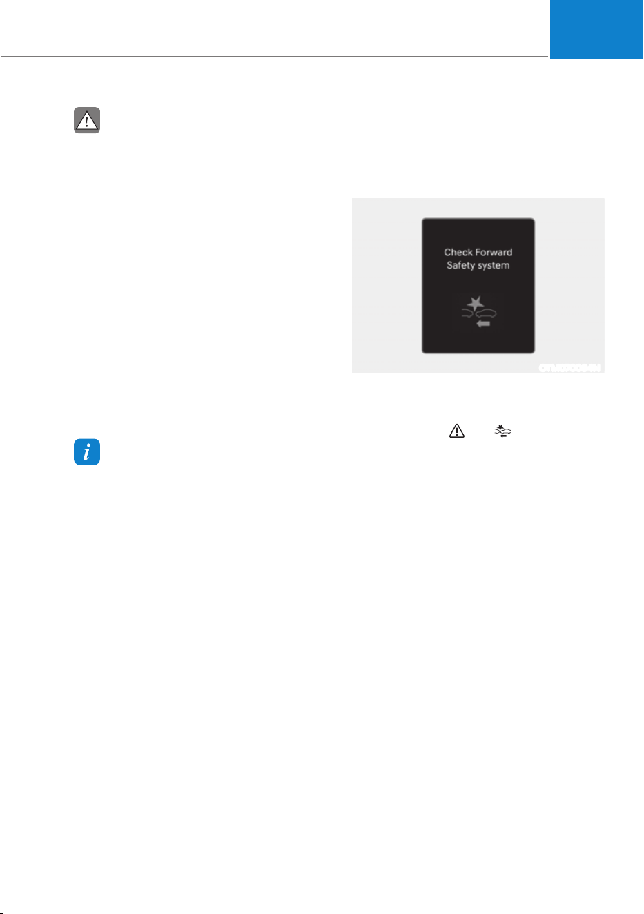
07
7-17
CAUTION
ś Depending on the condition of the
vehicle, pedestrian and cyclist in
front and the surroundings, the
speed range to operate Forward
Collision-Avoidance Assist may
reduce. Forward Collision-Avoidance
Assist may only warn the driver, or it
may not operate.
ś Forward Collision-Avoidance Assist
will operate under certain conditions
by judging the risk level based on
the condition of the oncoming
vehicle, driving direction, speed and
surroundings.
ś When a collision with a surrounding
vehicle is expected, Lane-Change
Oncoming, Lane-Change Side and
Evasive Steering Assist functions will
only warn the driver (if equipped).
Information
ś In a situation where collision is
imminent, braking may be assisted by
Forward Collision-Avoidance Assist
when braking is insufficient by the
driver.
ś The images and colors in the
instrument cluster may differ
depending on the cluster type or theme
selected from the instrument cluster.
Forward Collision-Avoidance
Assist Malfunction and
Limitations
Forward Collision-Avoidance Assist
malfunction
OTM070094N
When Forward Collision-Avoidance
Assist is not working properly, the ‘Check
Forward Safety’ warning message will
appear, and the
and warning lights
will illuminate on the cluster. Have the
vehicle be inspected by an authorized
HYUNDAI dealer.
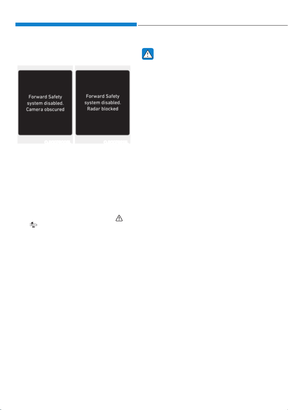
Driver Assistance System
7-18
Forward Collision-Avoidance Assist
disabled
OJX1079005L OJX1079212L
When the front windshield where the
front view camera is located, front radar
cover, bumper or sensor is covered with
foreign material, such as snow or rain, it
can reduce the detecting performance
and temporarily limit or disable Forward
Collision-Avoidance Assist.
If this occurs the ‘Forward Safety system
disabled. Camera obscured’ or the
‘Forward Safety system disabled. Radar
blocked’ warning message, and the
and
warning lights will illuminate on
the cluster.
Forward Collision-Avoidance Assist will
operate properly when snow, rain or
foreign material is removed.
If Forward Collision-Avoidance Assist
does not operate properly after
obstruction (snow, rain, or foreign
material) is removed (including trailer,
carrier, etc., from the rear bumper), have
the vehicle inspected by an HYUNDAI
dealer.
WARNING
ś Even though the warning message or
warning light does not appear on the
cluster, Forward Collision-Avoidance
Assist may not properly operate.
ś Forward Collision-Avoidance Assist
may not properly operate in an area
(for example, open terrain), where
any objects are not detected after
turning ON the vehicle.
Limitations of Forward Collision-
Avoidance Assist
Forward Collision-Avoidance Assist may
not operate properly, or it may operate
unexpectedly under the following
circumstances:
ś The detecting sensor or the
surroundings are contaminated or
damaged
ś The temperature around the front
view camera is high or low due to
surrounding environment
ś The camera lens is contaminated due
to tinted, filmed or coated windshield,
damaged glass, or sticky foreign
material (sticker, bug, etc.) on the
glass
ś Moisture is not removed or frozen on
the windshield
ś Washer fluid is continuously sprayed,
or the wiper is on
ś Driving in heavy rain or snow, or thick
fog
ś The field of view of the front view
camera is obstructed by sun glare
ś Street light or light from an oncoming
traffic is reflected on the wet road
surface, such as a puddle on the road
ś An object is placed on the dashboard

07
7-19
ś Your vehicle is being towed
ś The surrounding is very bright
ś The surrounding is very dark, such as
in a tunnel, etc.
ś The brightness changes suddenly, for
example when entering or exiting a
tunnel
ś The brightness outside is low, and the
headlamps are not on or are not bright
ś Driving through steam, smoke or
shadow
ś Only part of the vehicle, pedestrian or
cyclist is detected
ś The vehicle in front is a bus, heavy
truck, truck with an unusually shaped
cargo, trailer, etc.
ś The vehicle in front has no tail lights,
tail lights are located unusually, etc.
ś The brightness outside is low, and the
tail lamps are not on or are not bright
ś The rear of the front vehicle is small
or the vehicle does not look normal,
such as when the vehicle is tilted,
overturned, or the side of the vehicle
is visble, etc.
ś The front vehicle’s ground clearance is
low or high
ś A vehicle, pedestrian or cyclist
suddenly cuts in front
ś The bumper around the front radar is
impacted, damaged or the front radar
is out of position
ś The temperature around the front
radar is high or low
ś Driving through a tunnel or iron bridge
ś Driving in vast areas where there
are few vehicles or structures (for
example, desert, meadow, suburb,
etc.)
ś Driving near areas containing metal
substances, such as a construction
zone, railroad, etc.
ś A material is near that reflects very
well on the front radar, such as a
guardrail, nearby vehicle, etc.
ś The cyclist in front is on a bicycle
made of material that does not reflect
on the front radar
ś The vehicle in front is detected late
ś The vehicle in front is suddenly
blocked by an obstacle
ś The vehicle in front suddenly changes
lane or suddenly reduces speed
ś The vehicle in front is bent out of
shape
ś The front vehicle’s speed is fast or
slow
ś The vehicle in front steers in the
opposite direction of your vehicle to
avoid a collision
ś With a vehicle in front, your vehicle
changes lane at low speed
ś The vehicle in front is covered with
snow
ś You are departing or returning to the
lane
ś Unstable driving
ś You are on a roundabout and the
vehicle in front is not detected
ś You are continuously driving in a circle
ś The vehicle in front has an unusual
shape
ś The vehicle in front is driving uphill or
downhill
ś The pedestrian or cyclist is not
fully detected, for example, if the
pedestrian is leaning over or is not
fully walking upright
ś The pedestrian or cyclist is wearing
clothing or equipment that makes it
difficult to detect

Driver Assistance System
7-20
OADAS044
The illustration above shows the image
the front view camera and front radar
is capable of detecting as a vehicle,
pedestrian and cyclist.
ś The pedestrian or cyclist in front is
moving very quickly
ś The pedestrian or cyclist in front is
short or is posing a low posture
ś The pedestrian or cyclist in front has
impaired mobility
ś The pedestrian or cyclist in front is
moving intersected with the driving
direction
ś There is a group of pedestrians,
cyclists or a large crowd in front
ś The pedestrian or cyclist is wearing
clothing that easily blends into the
background, making it difficult to
detect
ś The pedestrian or cyclist is difficult to
distinguish from the similarly shaped
structure in the surroundings
ś You are driving by a pedestrian,
cyclist, traffic signs, structures, etc.,
near the intersection
ś Driving in a parking lot
ś Driving through a tollgate,
construction area, unpaved road,
partial paved road, uneven road,
speed bumps, etc.
ś Driving on an incline road, curved
road, etc.
ś Driving through a roadside with trees
or streetlights
ś The adverse road conditions cause
excessive vehicle vibrations while
driving
ś Your vehicle height is low or high
due to heavy loads, abnormal tire
pressure, etc.
ś Driving through a narrow road where
trees or grass are overgrown
ś There is interference by
electromagnetic waves, such as
driving in an area with strong radio
waves or electrical noise

07
7-21
Junction Crossing, Lane-Change
Oncoming, Lane-Change Side, Evasive
Steering Assist function (if equipped)
ś The temperature around the front
corner radar or rear corner radar is
high or low
ś A trailer or carrier is installed around
the rear corner radar
ś The front corner radar or rear corner
radar is covered with snow, rain, dirt,
etc.
ś The bumper around the front corner
radar or rear corner radar is covered
with objects, such as a bumper
sticker, bumper guard, bike rack, etc.
ś The bumper around the front corner
radar or rear corner radar is impacted,
damaged or the radar is out of
position
ś The front corner radar or rear corner
radar is blocked by other vehicles,
walls or pillars
ś Driving on a highway ramp
ś Driving on a road where the guardrail
or wall is in double structure
ś The other vehicle drives very close
behind your vehicle, or the other
vehicle passes by your vehicle in close
proximity
ś The speed of the other vehicle is very
fast that it passes by your vehicle in a
short time
ś Your vehicle passes by the other
vehicle
ś Your vehicle has started at the same
time as the vehicle next to you and
has accelerated
ś The vehicle in the next lane moves
two lanes away from you, or when the
vehicle two lanes away moves to the
next lane from you
ś A motorcycle or bicycle is detected
ś A vehicle such as a flat trailer is
detected
ś A big vehicle such as a bus or truck is
detected
ś A small moving obstacle such as a
pedestrian, animal, shopping cart or a
baby stroller is detected
ś A vehicle with low height such as a
sports car is detected
ś The lane is difficult to see due to
foreign material, such as rain, snow,
dust, sand, oil and water puddles
ś The color of the lane marking is not
distinguishable from the road
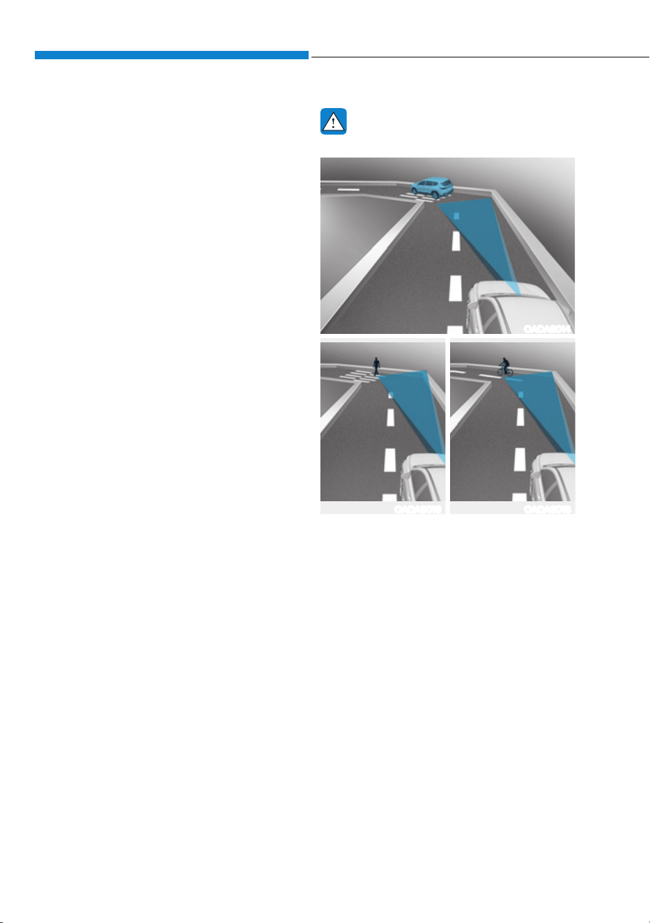
Driver Assistance System
7-22
ś There are markings on the road near
the lane or the markings on the road
looks similar to the lane markings
ś The shadow is on the lane marking by
a median strip, trees, guardrail, noise
barriers, etc.
ś The lane number increases or
decreases, or the lane markings are
crossing
ś There are more than two lane
markings on the road
ś The lane markings are complicated or
a structure substitutes for the lines,
such as a construction area
ś There are road markings, such as
zigzag lanes, crosswalk markings and
road signs
ś The lane suddenly disappears, such as
at the intersection
ś The lane is very wide or narrow
ś There is a curb or road edges without
a lane
ś The vehicle in front is driving with one
side on the lane marking
ś The distance to the front vehicle is
extremely short
WARNING
ś Driving on a curved road
OADAS014
OADAS016 OADAS018
Forward Collision-Avoidance Assist
may not detect other vehicles,
pedestrians or cyclists in front of
you while driving on curved roads
adversely affecting the performance
of the sensors. This may result in no
warning, braking assist or steering
assist (if equipped) when necessary.
When driving on a curved road,
you must maintain a safe braking
distance, and if necessary, steer the
vehicle and depress the brake pedal
to reduce your driving speed in order
to maintain a safe distance.
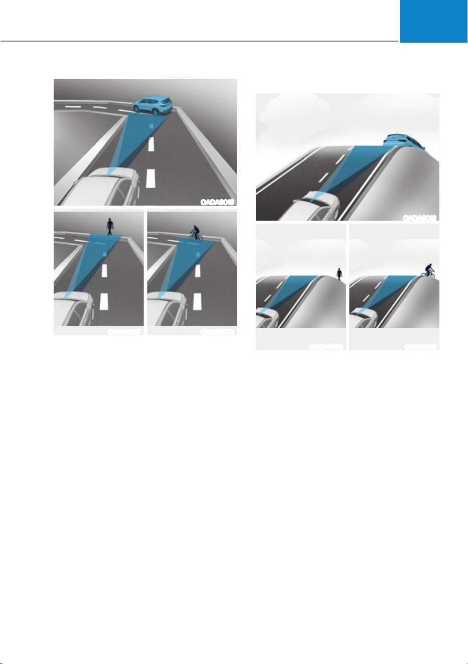
07
7-23
OADAS015
OADAS017 OADAS019
Forward Collision-Avoidance Assist
may detect a vehicle, pedestrian or
cyclist in the next lane or outside the
lane when driving on a curved road.
If this occurs, Forward Collision-
Avoidance Assist may unnecessarily
warn the driver and control the brake
or steering wheel (if equipped).
Always check the traffic conditions
around the vehicle.
ś Driving on an inclined road
OADAS012
OADAS010 OADAS011
Forward Collision-Avoidance Assist
may not detect other vehicles,
pedestrians or cyclists in front of
you while driving uphill or downhill,
adversely affecting the performance
of the sensors.
This may result in unnecessary
warning, braking assist or steering
assist (if equipped) or no warning,
braking assist or steering assist (if
equipped) when necessary.
Also, vehicle speed may rapidly
decrease when a vehicle, pedestrian
or cyclist ahead is suddenly
detected.
Always have your eyes on the road
while driving uphill or downhill and
if necessary, steer your vehicle and
depress the brake pedal to reduce
your driving speed in order to
maintain a safe distance.
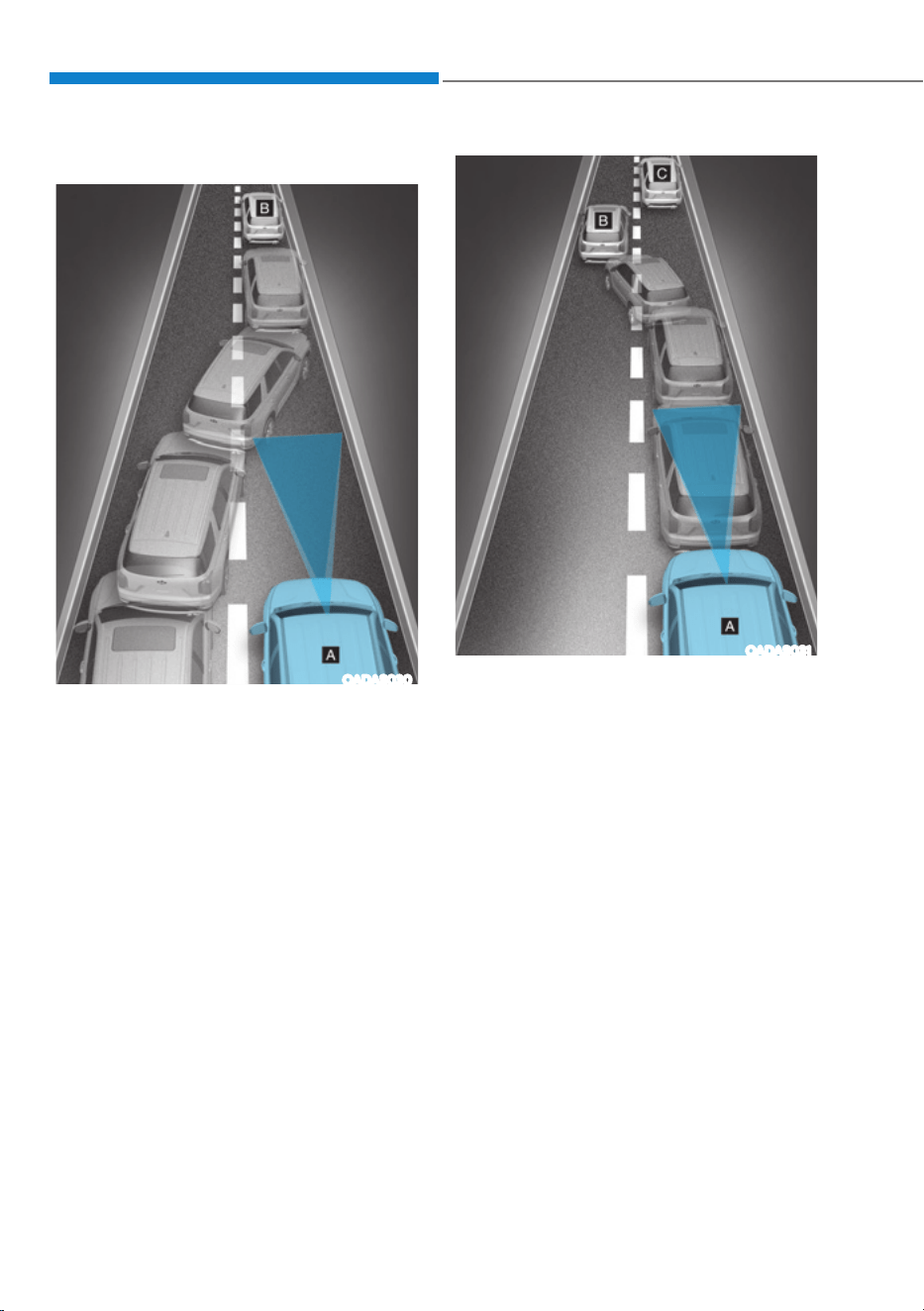
Driver Assistance System
7-24
ś Changing lanes
OADAS030
[A] : Your vehicle, [B] : Lane changing vehicle
When a vehicle moves into your lane
from an adjacent lane, it cannot
be detected by the sensor until it
is in the sensor's detection range.
Forward Collision-Avoidance Assist
may not immediately detect the
vehicle when the vehicle changes
lanes abruptly. In this case, you must
maintain a safe braking distance,
and if necessary, steer your vehicle
and depress the brake pedal to
reduce your driving speed in order to
maintain a safe distance.
OADAS031
[A] : Your vehicle, [B] : Lane changing vehicle,
[C] : Same lane vehicle
When a vehicle in front of you
merges out of the lane, Forward
Collision-Avoidance Assist may not
immediately detect the vehicle that
is now in front of you. In this case,
you must maintain a safe braking
distance, and if necessary, steer your
vehicle and depress the brake pedal
to reduce your driving speed in order
to maintain a safe distance.
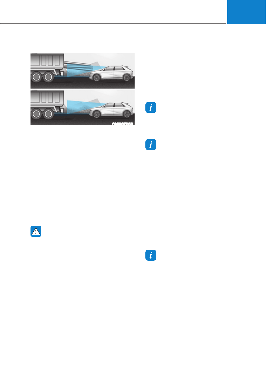
07
7-25
ś Detecting vehicle
ONE1071156
If the vehicle in front of you has
cargo that extends rearward from
the cab, or when the vehicle in front
of you has higher ground clearance,
additional special attention is
required. Forward Collision-
Avoidance Assist may not be able
to detect the cargo extending from
the vehicle. In these instances,
you must maintain a safe braking
distance from the rearmost object,
and if necessary, steer your vehicle
and depress the brake pedal to
reduce your driving speed in order to
maintain distance.
WARNING
ś When you are towing a trailer or
another vehicle, turn off Forward
Collision-Avoidance Assist for to
safety reasons.
ś Forward Collision-Avoidance Assist
may operate if objects that are
similar in shape or characteristics to
vehicles, pedestrians and cyclists are
detected.
ś Forward Collision-Avoidance Assist
does not operate on bicycles,
motorcycles, or smaller wheeled
objects, such as luggage bags,
shopping carts, or strollers.
ś Forward Collision-Avoidance
Assist may not operate properly if
interfered by strong electromagnetic
waves.
ś Forward Collision-Avoidance Assist
may not operate for 15 seconds after
the vehicle is started, or the front
view camera is initialized.
Information
In some instances, FCA system
may be canceled when subjected to
electromagnetic interference.
Information
This device complies with Part 15 of the
FCC rules.
Operation is subject to the following three
conditions:
1. This device may not cause harmful
interference, and
2. This device must accept any
interference received, including
interference that may cause undesired
operation of the device.
3. Changes or modifications not expressly
approved by the party responsible
for compliance could void the user's
authority to operate the device.
Information
Radio frequency radiation exposure
information:
This equipment complies with FCC
radiation exposure limits set forth for an
uncontrolled environment.
This equipment should be installed and
operated with minimum distance of 8 in.
(20 cm) between the radiator (antenna)
and your body.
This transmitter must not be co-located or
operating in conjunction with any other
antenna or transmitter.
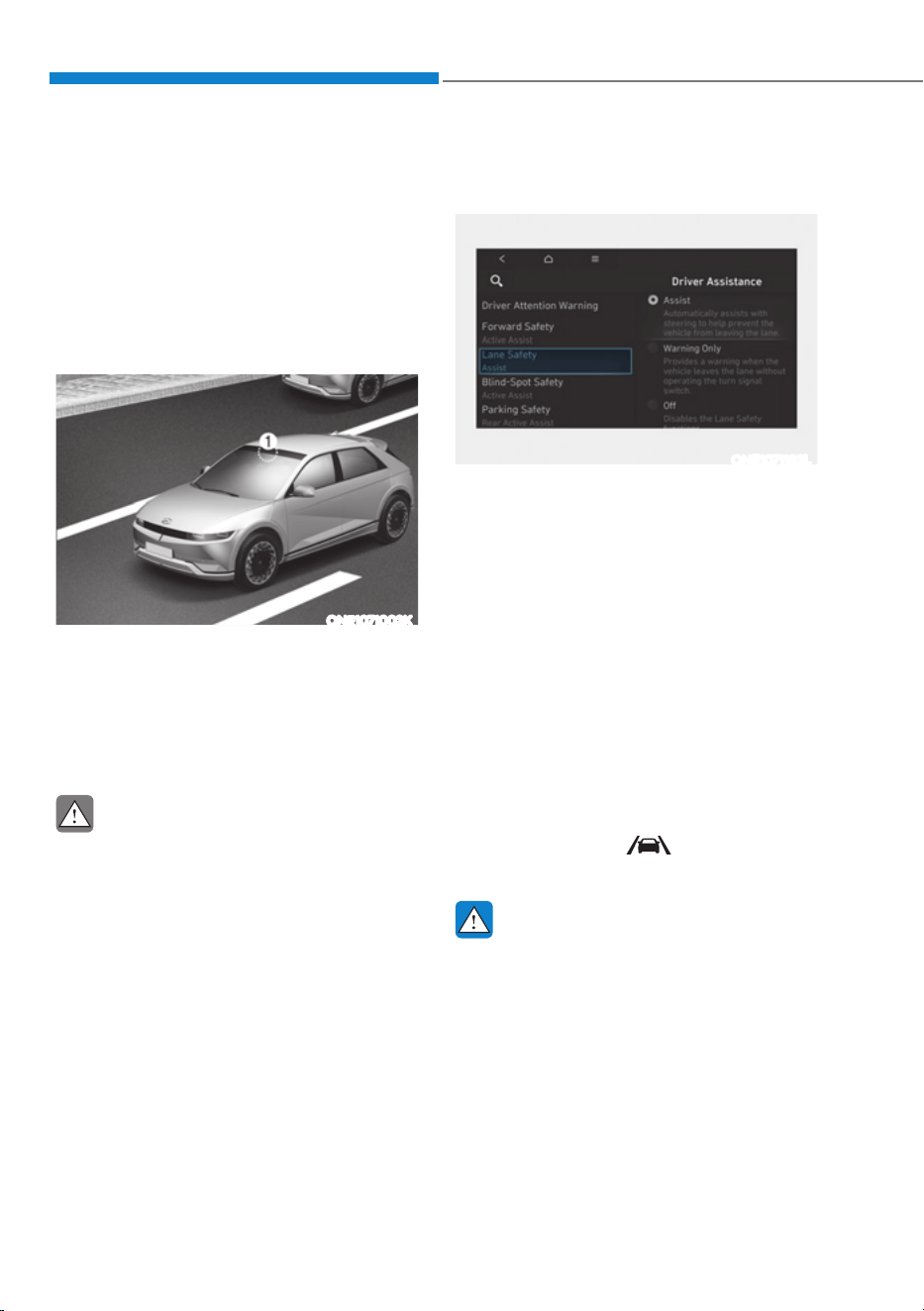
Driver Assistance System
7-26
Lane Keeping Assist is designed to help
detect lane markings (or road edges)
while driving over a certain speed. Lane
Keeping Assist will warn the driver if the
vehicle leaves the lane without using the
turn signal, or will automatically assist
the driver’s steering to help prevent the
vehicle from departing the lane.
Detecting sensor
ONE1071002K
[1] : Front view camera
The front view camera is used as a
detecting sensor to detect lane markings
(or road edges).
Refer to the picture above for the
detailed location of the detecting sensor.
CAUTION
For more details on the precautions
of the front view camera, refer to
“Forward Collision-Avoidance Assist
(FCA)” section in this chapter.
Lane Keeping Assist Settings
Setting features
ONE1071192L
Lane Safety
With the vehicle on, select or deselect
œ'ULYHU$VVLVWDQFHƟ/DQH6DIHW\ŔIURP
the Settings menu to set whether to use
each function.
- If ‘Assist’ is selected, Lane Keeping
Assist will automatically assist the
driver’s steering when lane departure
is detected to help prevent the vehicle
from moving out of its lane.
- If 'Warning Only' is selected, Lane
Keeping Assist will warn the driver
with an audible warning when lane
departure is detected. The driver must
steer the vehicle.
- If ‘Off’ is selected, Lane Keeping Assist
will turn off. The
indicator light
will turn off on the cluster.
WARNING
ś If 'Warning Only' is selected, steering
is not assisted.
ś Lane Keeping Assist does not control
the steering wheel when the vehicle
is driven in the middle of the lane.
ś The driver should always be aware
of the surroundings and steer the
vehicle if ‘Off’ is selected.
/$1(.((3,1*$66,67ǣ/.$Ǥ
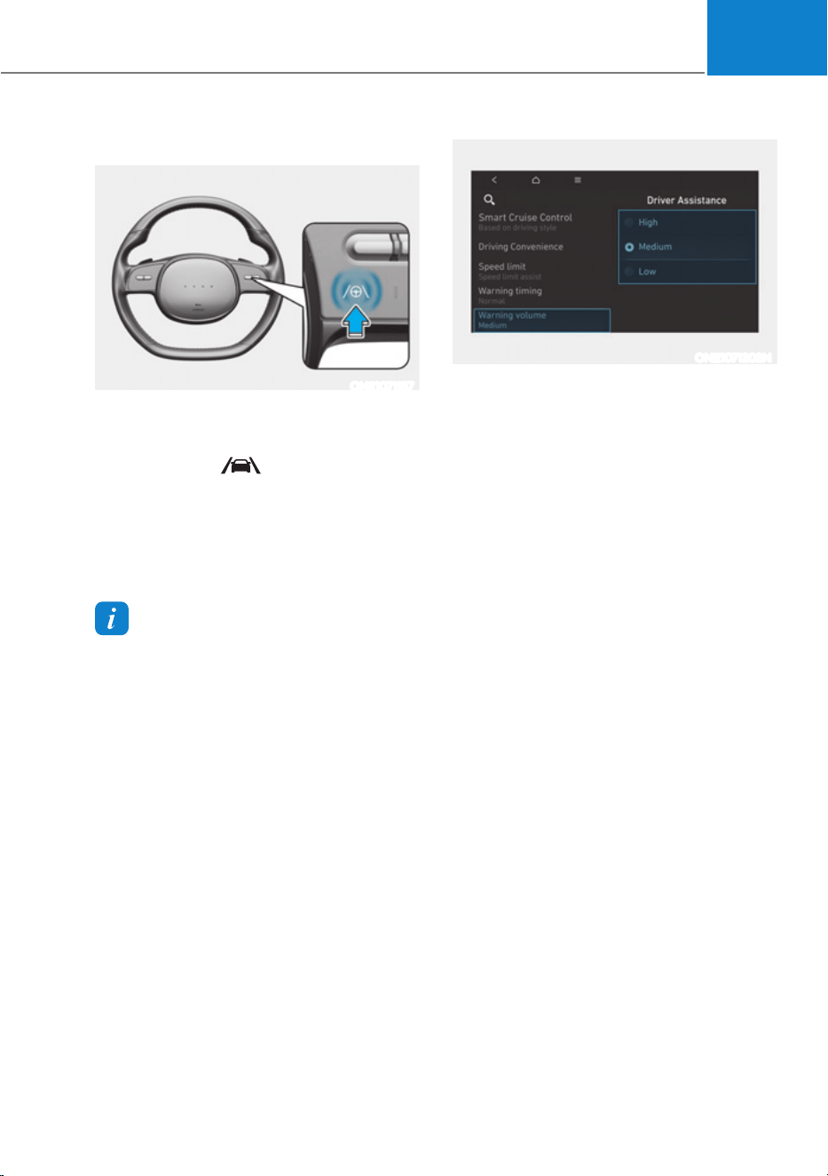
07
7-27
Turning Lane Keeping Assist On/Off
ONE1071157
With the vehicle on, press and hold the
Lane Driving Assist button located on the
steering wheel to turn on Lane Keeping
Assist. The grey
indicator light will
illuminate on the cluster.
Press and hold the button again to turn
off the function.
If the vehicle is restarted, Lane Keeping
Assist will maintain the last setting.
Information
ś When the Lane Driving Assist button is
pressed shortly, Lane Following Assist
will turn on and off.
ś When Lane Keeping Assist is turned
off with the Lane Driving Assist button,
the Lane Safety setting also changes to
'Off'.
ONE1071202N
Warning Volume
With the vehicle on, select ‘Driver
$VVLVWDQFHƟ:DUQLQJ9ROXPHŔIURPWKH
Settings menu to change the Warning
Volume to ‘High’, ‘Medium’ or ‘Low’ for
Lane Keeping Assist.
If you change the warning volume,
the Warning Volume of other Driver
Assistance systems may change.
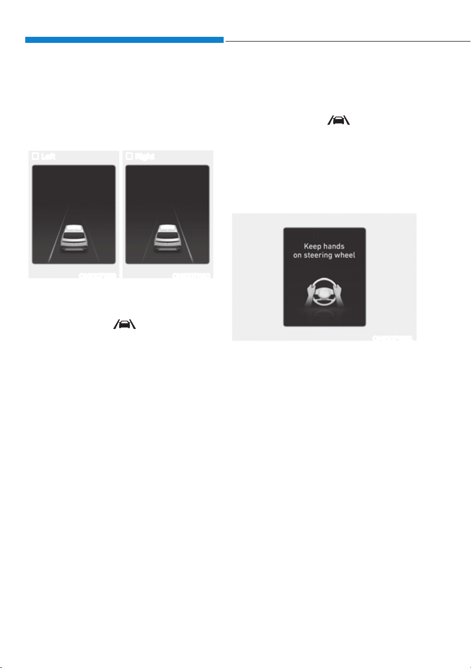
Driver Assistance System
7-28
Lane Keeping Assist Operation
Warning and control
Lane Keeping Assist will warn and help
control the vehicle with Lane Departure
Warning and Lane Keeping Assist.
Left Right
ONE1071159 ONE1071160
Lane Departure Warning
ś To warn the driver that the vehicle is
departing from the projected lane in
front, the green
indicator light
will blink on the cluster, the lane line
will blink on the cluster depending on
which direction the vehicle is veering,
and an audible warning will sound.
ś Lane Keeping Assist will operate
when your vehicle speed is between
approximately 40
- 120 mph (60 - 200
km/h).
Lane Keeping Assist
ś To warn the driver that the vehicle
is departing from the projected lane
in front, the green
indicator
light will blink on the cluster, and the
steering wheel will make adjustments
to keep vehicle inside the lane.
ś Lane Keeping Assist will operate
when your vehicle speed is between
approximately 40
- 120 mph (60 - 200
km/h).
ONE1071193L
Hands-off warning
If the driver takes their hands off the
steering wheel for several seconds, the
‘Place hands on the steering wheel’
warning message will appear on the
cluster, and an audible warning will
sound in stages.
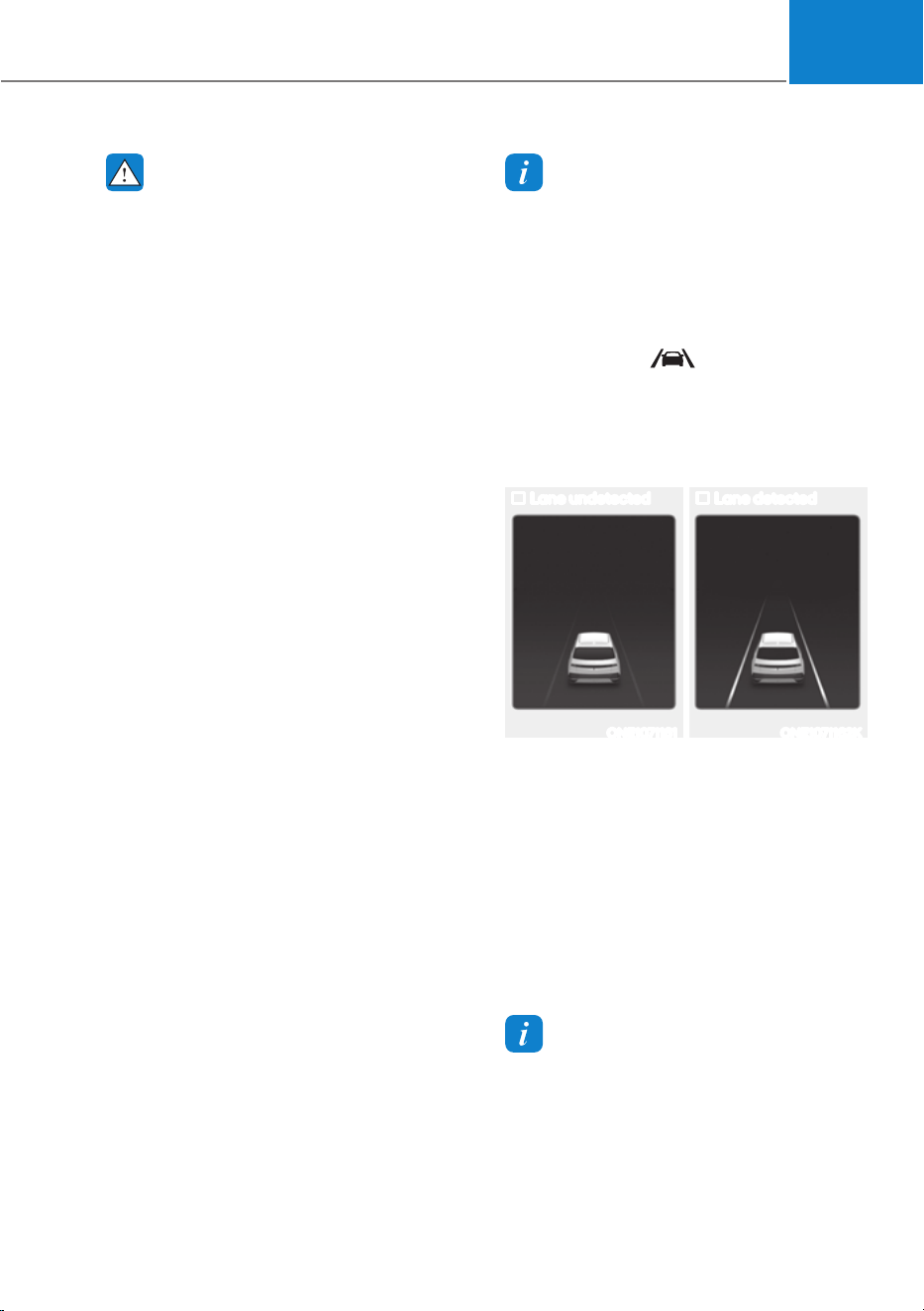
07
7-29
WARNING
ś The steering wheel may not be
assisted if the steering wheel is held
very tight or the steering wheel is
steered over a certain degree.
ś Lane Keeping Assist does not operate
at all times. It is the responsibility of
the driver to safely steer the vehicle
and to maintain the vehicle in its
lane.
ś The hands–off warning message
may appear late depending on road
conditions. Always have your hands
on the steering wheel while driving.
ś If the steering wheel is held very
lightly, the hands–off warning
message may appear because Lane
Keeping Assist may not recognize
that the driver has their hands on the
steering wheel.
ś If you attach objects to the steering
wheel, the hands-off warning may
not work properly.
Information
ś For more details on setting the
functions in the infotainment system,
refer to “Vehicle Settings” section in
chapter 4.
ś When lane markings (or road edges)
are detected, the lane lines on the
cluster will change from grey to white
and the green
indicator light will
illuminate.
ś When the lane markings (or road
edges) are detected and Highway Lane
Change Assist is on, the lane lines on
the cluster may change to green.
Lane undetected Lane detected
ONE1071161 ONE1071162K
ś The images and colors in the
instrument cluster may differ
depending on the cluster type or theme
selected from the instrument cluster.
ś Even though the steering is assisted by
Lane Keeping Assist, the driver may
control the steering wheel.
ś The steering wheel may feel heavier
or lighter when the steering wheel is
assisted by Lane Keeping Assist than
when it is not.
Information
The images or colors may be displayed
differently depending on the specifications
of the instrument panel or theme.
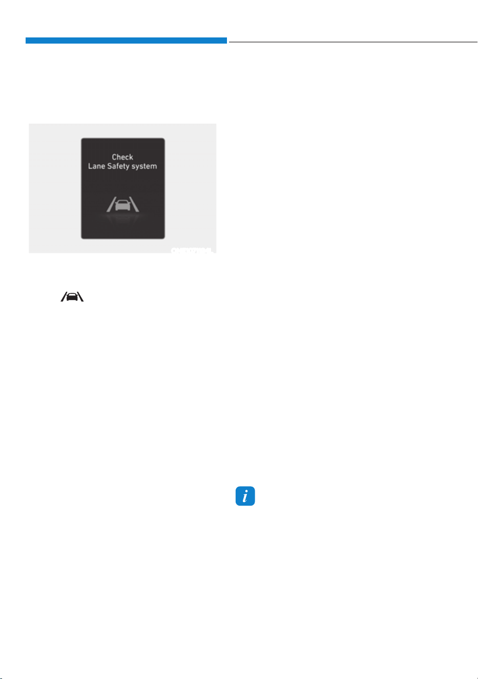
Driver Assistance System
7-30
Lane Keeping Assist Malfunction
and Limitations
Lane Keeping Assist malfunction
ONE1071194L
When Lane Keeping Assist is not working
properly, the ‘Check Lane Safety system’
warning message will appear and the
yellow
indicator light will illuminate
on the cluster. If this occurs, have the
vehicle be inspected by an authorized
HYUNDAI dealer.
Limitations of Lane Keeping Assist
Lane Keeping Assist may not operate
properly or may operate unexpectedly
under the following circumstances:
ś The lane is contaminated or difficult
to detect because:
- The lane markings (or road edge)
are covered with rain, snow, dirt,
oil, etc.
- The color of the lane marking (or
road edge) is not distinguishable
from the road
- There are markings (or road
edges) on the road near the lane
or the markings (or road edges) on
the road look similar to the lane
markings (or road edge)
- The lane marking (or road edge) is
indistinct or damaged
- The shadow is on the lane marking
(or road edge) by a median strip,
trees, guardrail, noise barriers, etc.
ś The number of lanes change or the
lanes merge
ś There are more than two lane
markings (or road edges) on the road
ś The lane markings (or road edges) are
complicated or a structure substitutes
for the lines, such as a construction
area
ś There are road markings, such as
zigzag lanes, crosswalk markings and
road signs
ś The lane suddenly disappears, such as
at the intersection
ś The lane (or road width) is very wide
or narrow
ś There is a road edge without a lane
ś There is a boundary structure in the
roadway, such as a tollgate, sidewalk,
curb, etc.
ś The distance to the front vehicle is
extremely short or the vehicle in front
is covering the lane marking (or road
edge)
Information
For more details on the limitations of the
front view camera, refer to “Forward
Collision-Avoidance Assist (FCA)” section
in this chapter.

07
7-31
WARNING
Take the following precautions when
using Lane Keeping Assist:
ś The driver should hold the
responsibility to safely drive and
control the vehicle. Do not solely rely
on Lane Keeping Assist and drive
dangerously.
ś The operation of Lane Keeping Assist
can be canceled or not work properly
depending on road conditions and
surroundings. Always be cautious
while driving.
ś Refer to “Limitations of Lane Keeping
Assist” if the lane is not detected
properly.
ś When you are towing a trailer or
another vehicle, turn off Lane
Keeping Assist for safety reasons.
ś If the vehicle is driven at high speed,
the steering wheel will not be
controlled. The driver must always
follow the speed limit when using
Lane Keeping Assist.
ś If any other system’s warning
message is displayed or audible
warning is generated, Lane Keeping
Assist warning message may not be
displayed and audible warning may
not be generated.
ś You may not hear the warning
sound of Lane Keeping Assist if the
surrounding is noisy.
ś If you attach objects to the steering
wheel, steering may not be assisted
properly.
ś Lane Keeping Assist may not operate
for 15 seconds after the vehicle is
started, or the front view camera is
initialized.
ś Lane Keeping Assist will not operate
when:
- The turn signal or hazard warning
flasher is turned on.
- The vehicle is not driven in the
center of the lane when Lane
Keeping Assist is turned on or right
after changing a lane.
- ESC (Electronic Stability Control)
or VSM (Vehicle Stability
Management) is activated.
- The vehicle is driven on a sharp
curve.
- Vehicle speed is below 35 mph
(55 km/h) or above 130 mph
(210 km/h).
- The vehicle makes sharp lane
changes.
- The vehicle brakes suddenly.

Driver Assistance System
7-32
Blind-Spot Collision-Avoidance Assist
is designed to help detect and monitor
approaching vehicles in the driver’s
blind spot area and warn the driver
of a possible collision with a warning
message and audible warning.
In addition, if there is a risk of collision
when changing lanes or driving forward
out of a parking space, Blind-Spot
Collision-Avoidance Assist will help avoid
collision by applying the brake.
OJX1079256
Blind-Spot Collision-Avoidance Assist
helps detect and informs the driver that a
vehicle is in the blind spot.
CAUTION
The detecting range may vary
depending on the speed of your
vehicle. Even if there is a vehicle in the
blind spot area, Blind-Spot Collision-
Avoidance Assist may not warn you
when you pass by at high speeds.
OJX1079026
Blind-Spot Collision-Avoidance Assist
helps detect and informs the driver that
a vehicle is approaching at high speed
from the blind spot area.
CAUTION
Warning timing may vary depending on
the speed of the vehicle approaching at
high speed.
OJX1079027
When changing lanes by detecting
the lane ahead, if Blind-Spot Collision-
Avoidance Assist judges that there is
a collision risk with an approaching
vehicle in the blind spot, it will help avoid
collision by applying the brake.
%/,1'ǘ6327&2//,6,21ǘ$92,'$1&($66,67ǣ%&$Ǥ
ǣ,)(48,33('Ǥ
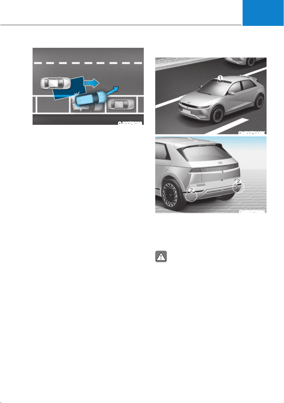
07
7-33
OJX1079028
When you are driving forward out of a
parking space, if Blind-Spot Collision-
Avoidance Assist judges that there is a
collision risk with an approaching vehicle
in the blind spot, it helps avoid collision
by applying the brake.
Detecting sensor
ONE1071002K
ONE1071163N
[1] : Front view camera, [2] : Rear corner radar
Refer to the picture above for the
detailed location of the detecting
sensors.
CAUTION
Take the following precautions to
maintain optimal performance of the
detecting sensor:
ś Never disassemble the rear corner
radar or radar assembly, or cause any
damage to it.
ś If the rear corner radar or near the
radar has been damaged or impacted
in any way, even though the warning
message does not appear on
the cluster, Blind-Spot Collision-
Avoidance Assist system may not
operate properly. Have the vehicle be
inspected by an authorized HYUNDAI
dealer.
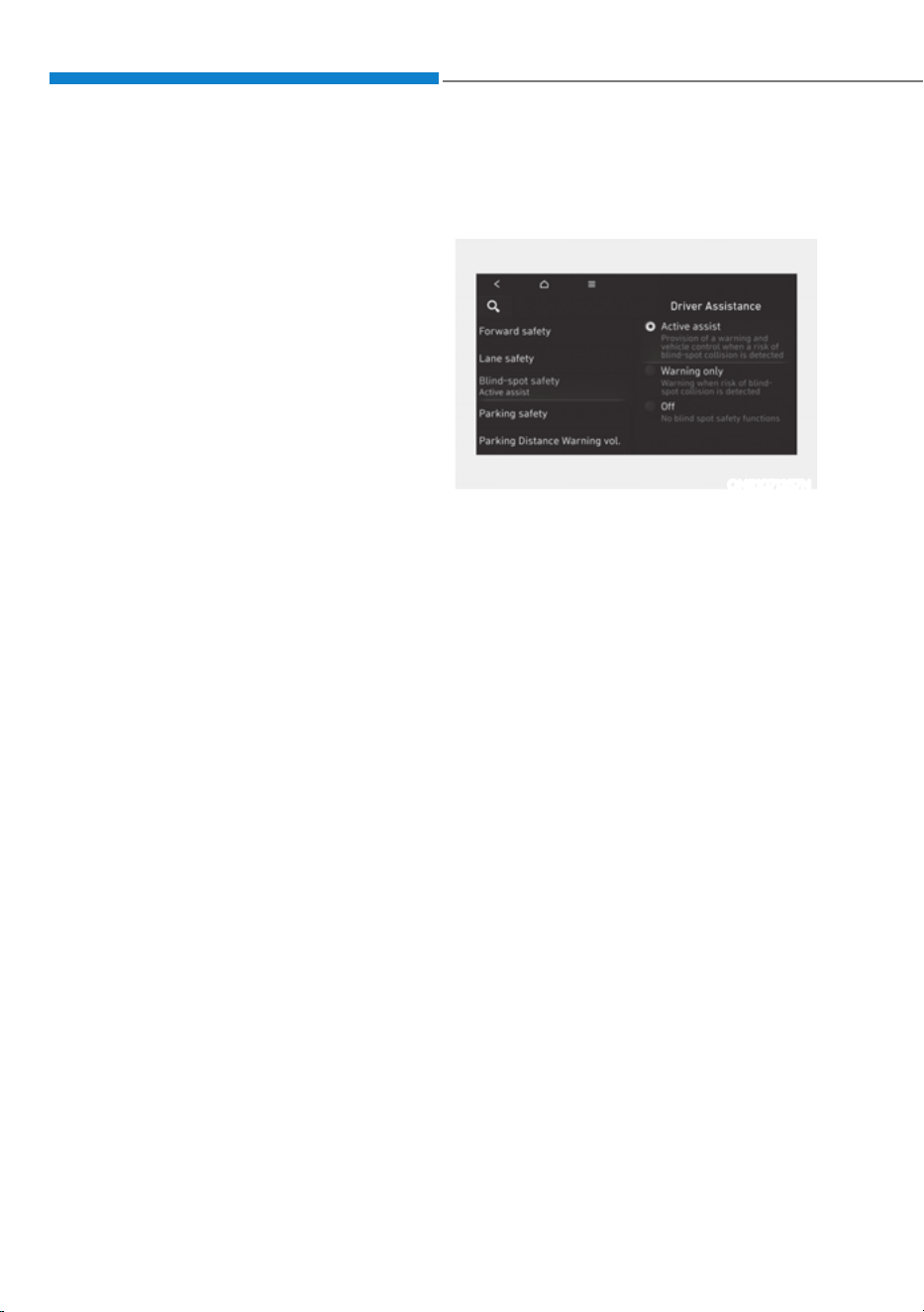
Driver Assistance System
7-34
ś If the rear corner radars have
been replaced or repaired, have
the vehicle be inspected by an
authorized HYUNDAI dealer.
ś Use only genuine parts to repair the
rear bumper where the rear corner
radar is located.
ś Do not apply license plate frame or
objects, such as a bumper sticker,
film or a bumper guard near the rear
corner radar.
ś Blind-Spot Collision-Avoidance
Assist may not work properly if the
bumper have been replaced, or the
surroundings of the rear corner radar
has been damaged or paint has been
applied.
ś If a trailer, carrier, etc., is installed,
it may adversely affect the
performance of the rear corner radar
or Blind-Spot Collision-Avoidance
Assist may not operate.
ś For more details on the precautions
of the front view camera, refer to
“Forward Collision-Avoidance Assist
(FCA)” section in this chapter.
Blind-Spot Collision-Avoidance
Assist Settings
Setting features
ONE1071257N
Blind-Spot Safety
With the vehicle on, select or deselect
œ'ULYHU$VVLVWDQFHƟ%OLQG6SRW6DIHW\Ŕ
from the Settings menu to set whether to
use each function.
- If ‘Active Assist’ is selected, Blind-Spot
Collision-Avoidance Assist will warn
the driver with a warning message,
an audible warning depending on the
collision risk levels. Braking assist will
be applied depending on the collision
risk levels.
- If ‘Warning Only’ is selected, Blind-
Spot Collision-Avoidance Assist
will warn the driver with a warning
message, an audible warning
depending on the collision risk levels.
Braking will not be assisted.
- If ‘Off’ is selected, Blind-Spot
Collision-Avoidance Assist will turn
off.

07
7-35
OTM070097N
When the vehicle is restarted with
Blind-Spot Collision-Avoidance Assist
off, the ‘Blind-Spot Safety System is Off’
message will appear on the cluster.
If you change the setting from ‘Off’ to
‘Active Assist’ or ‘Warning Only’, the
warning light on the side view mirror will
blink for three seconds.
In addition, if the vehicle is turned on,
when Blind-Spot Collision-Avoidance
Assist is set to ‘Active Assist’ or ‘Warning
Only’, the warning light on the side view
mirror will blink for three seconds.
WARNING
ś If ‘Warning Only’ is selected, braking
is not assisted.
ś If ‘Off’ is selected, the driver should
always be aware of the surroundings
and drive safely.
Information
If the vehicle is restarted, Blind-Spot
Collision-Avoidance Assist will maintain
the last setting.
ONE1071282N
Warning Timing
With the vehicle on, select ‘Driver
$VVLVWDQFHƟ:DUQLQJ7LPLQJŔIURPWKH
Settings menu to change the initial
warning activation time for Blind-Spot
Collision-Avoidance Assist.
When the vehicle is first delivered,
Warning Timing is set to ‘Normal’. If you
change the Warning Timing, the Warning
Timing of other Driver Assistance
systems may change.
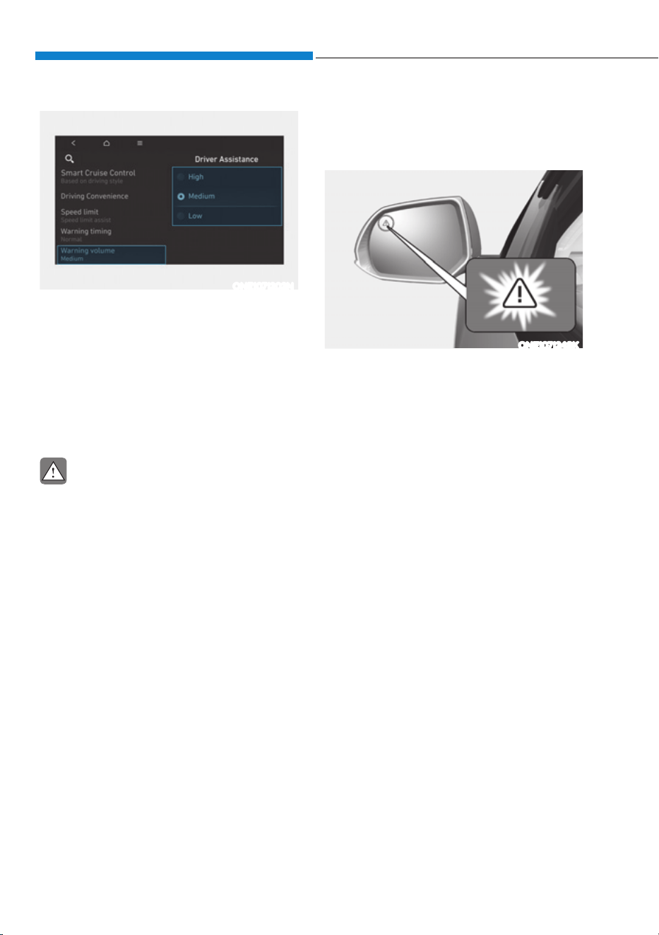
Driver Assistance System
7-36
ONE1071202N
Warning Volume
With the vehicle on, select ‘Driver
$VVLVWDQFHƟ:DUQLQJ9ROXPHŔIURPWKH
Settings menu to change the Warning
Volume to ‘High’, ‘Medium’ or ‘Low’ for
Blind-Spot Collision-Avoidance Assist.
If you change the warning volume,
the Warning Volume of other Driver
Assistance systems may change.
CAUTION
ś The setting of the Warning Timing
and Warning Volume applies to all
functions of Blind-Spot Collision-
Avoidance Assist.
ś Even though ‘Normal’ is selected
for Warning Timing, if a vehicle
approaches at high speed, the
warning may seem late.
ś Select ‘Late’ for Warning Timing
when traffic is light and when driving
speed is slow.
Blind-Spot Collision-Avoidance
Assist Operation
Warning and control
ONE1071248K
Vehicle detection
ś To warn the driver a vehicle is
detected, the warning light on the
side view mirror and head-up display
(if equipped) will illuminate.
ś Blind-Spot Collision-Avoidance Assist
will operate when your vehicle speed
is above 12 mph (20 km/h) and the
speed of the vehicle in the blind spot
area is above 7 mph (10 km/h).

07
7-37
Collision warning
ś Collision warning will operate when
the turn signal is turned on in the
direction of the detected vehicle.
ś If ‘Warning Only’ is selected from the
Settings menu, the collision warning
will operate when your vehicle
approaches the lane the blind spot
vehicle is detected.
ś To warn the driver of a collision, the
warning light on the outside side
view mirror and head-up display (if
equipped) will blink. At the same time,
an audible warning will sound.
ś When the turn signal is turned off or
you move away from the lane, the
collision warning will be canceled and
Blind-Spot Collision-Avoidance Assist
will return to vehicle detection state.
WARNING
ś The detecting range of the rear
corner radar is determined by a
standard road width, therefore, on
a narrow road, Blind-Spot Collision-
Avoidance Assist may detect other
vehicles two lanes over and warn
you. In contrast, on a wide road,
Blind-Spot Collision-Avoidance
Assist may not be able to detect a
vehicle driving in the next lane and
may not warn you.
ś When the hazard warning flasher is
on, the collision warning by the turn
signal will not operate.
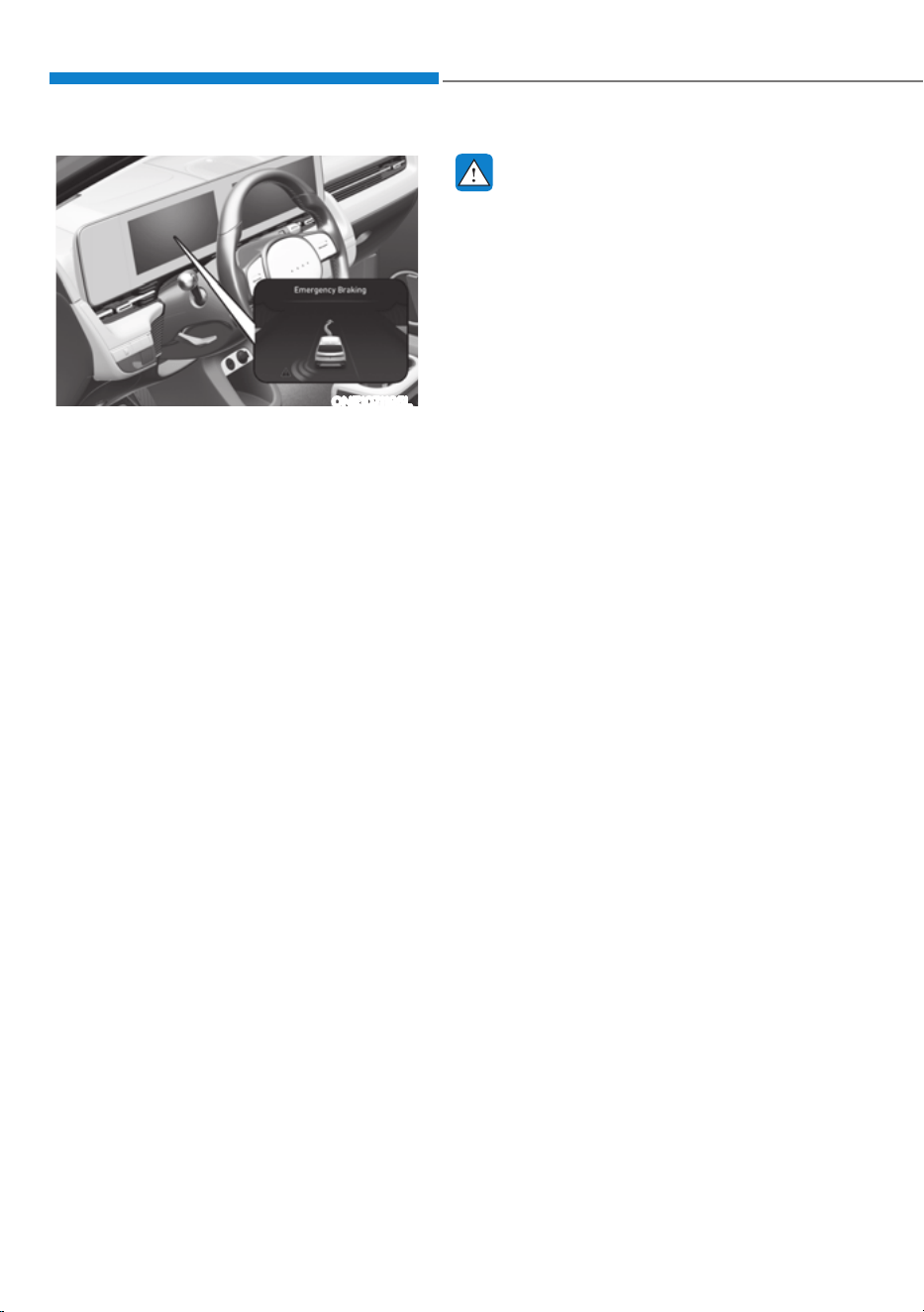
Driver Assistance System
7-38
ONE1071195L
Collision-avoidance assist (while driving)
ś To warn the driver of a collision, the
warning light on the side view mirror
will blink and a warning message will
appear on the cluster. At the same
time, an audible warning will sound,
warning light on the head-up display
(if equipped) will blink.
ś Blind-Spot Collision-Avoidance Assist
will operate when your vehicle speed
is between 40
- 120 mph (60 - 200
km/h) and both lane markings of the
driving lane are detected.
ś Emergency braking will be assisted to
help prevent collision with the vehicle
in the blind spot area.
WARNING
ś Collision-Avoidance Assist will
be canceled under the following
circumstances:
- Your vehicle enters the next lane
by a certain distance
- Your vehicle is away from the
collision risk
- The steering wheel is sharply
steered
- The brake pedal is depressed
- Forward Collision-Avoidance Assist
is operating
ś After Blind-Spot Collision-Avoidance
Assist operation or changing lane,
you must drive to the center of the
lane. Blind-Spot Collision-Avoidance
Assist will not operate if the vehicle is
not driven in the center of the lane.
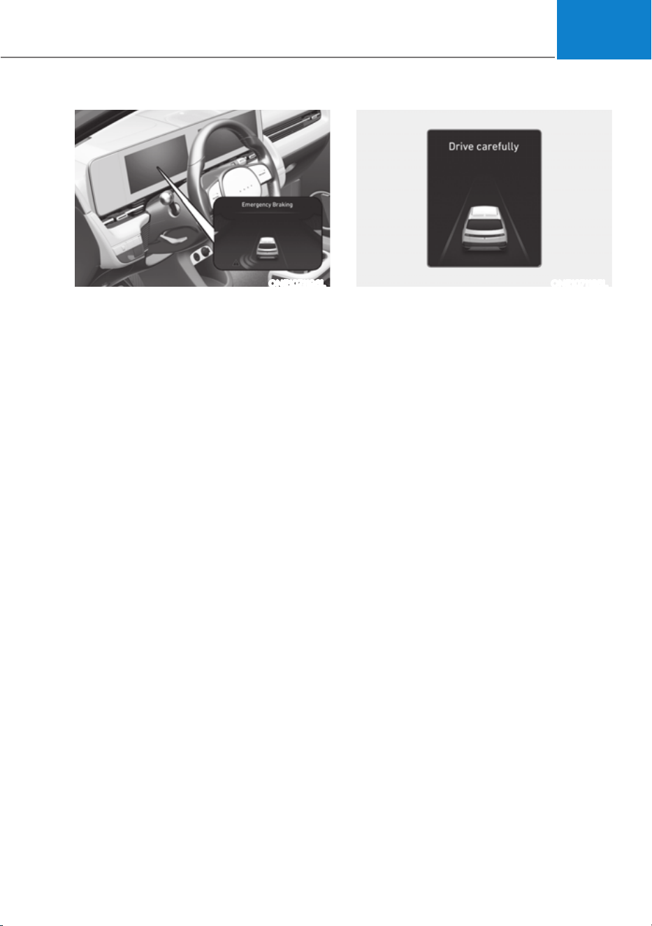
07
7-39
ONE1071196L
Collision-avoidance assist (while
departing)
ś To warn the driver of a collision, the
warning light on the side view mirror
will blink and a warning message will
appear on the cluster. At the same
time, an audible warning will sound,
warning light on the head-up display
(if equipped) will blink.
ś Blind-Spot Collision-Avoidance Assist
will operate when your vehicle speed
is below 2 mph (3 km/h) and the
speed of the vehicle in the blind spot
area is above 3 mph (5 km/h).
ś Emergency braking will be assisted to
help prevent collision with the vehicle
in the blind spot area.
ONE1071185L
ś When the vehicle is stopped due
to emergency braking, the ‘Drive
carefully’ warning message will
appear on the cluster.
For your safety, the driver should
depress the brake pedal immediately
and check the surroundings.
ś Brake control will end after the vehicle
is stopped by emergency braking for
approximately 2 seconds.

Driver Assistance System
7-40
WARNING
Take the following precautions when
using Blind-Spot Collision-Avoidance
Assist:
ś For your safety, change the Settings
after parking the vehicle at a safe
location.
ś If any other system’s warning
message is displayed or audible
warning is generated, Blind-Spot
Collision-Avoidance Assist’s warning
message may not be displayed
and audible warning may not be
generated.
ś You may not hear the warning sound
of Blind-Spot Collision-Avoidance
Assist if the surrounding is noisy.
ś Blind-Spot Collision-Avoidance
Assist may not operate if the driver
applies the brake pedal to avoid
collision.
ś When Blind-Spot Collision-Avoidance
Assist is operating, braking control
by the system will automatically
cancel when the driver excessively
depresses the accelerator pedal or
sharply steers the vehicle.
ś During Blind-Spot Collision-
Avoidance Assist operation, the
vehicle may stop suddenly injuring
passengers and shifting loose
objects. Always have the seat belt on
and keep loose objects secured.
ś Even if there is a problem with Blind-
Spot Collision-Avoidance Assist, the
vehicle’s basic braking performance
will operate properly.
ś Blind-Spot Collision-Avoidance Assist
does not operate in all situations or
cannot avoid all collisions.
ś Blind-Spot Collision-Avoidance
Assist may warn the driver late or
may not warn the driver depending
on the road and driving conditions.
ś Driver should maintain control of the
vehicle at all times. Do not depend
on Blind-Spot Collision-Avoidance
Assist. Maintain a safe braking
distance, and if necessary, depress
the brake pedal to reduce driving
speed or to stop the vehicle.
ś Never operate Blind-Spot Collision-
Avoidance Assist on people, animal,
objects, etc. It may cause serious
injury or death.
WARNING
The brake control may not operate
properly depending on the status of
ESC (Electronic Stability Control).
There will only be a warning when:
- The ESC (Electronic Stability Control)
warning light is on
- ESC (Electronic Stability Control) is
engaged in a different function
Information
The images or colors may be displayed
differently depending on the specifications
of the instrument panel or theme.
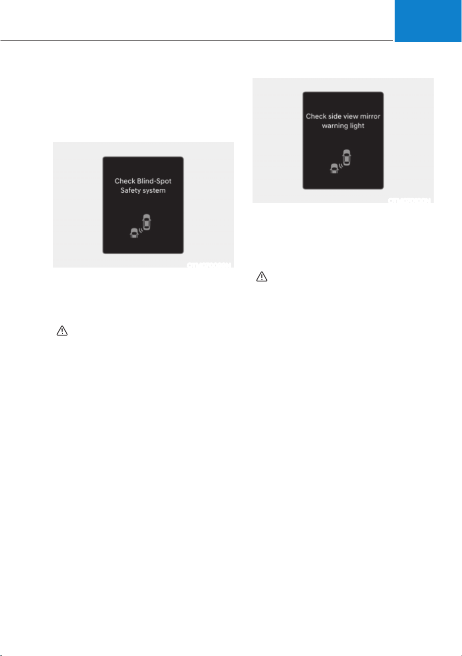
07
7-41
Blind-Spot Collision-Avoidance
Assist Malfunction and
Limitations
Blind-Spot Collision-Avoidance
Assist malfunction
OTM070099N
When Blind-Spot Collision-Avoidance
Assist is not working properly, the ‘Check
Blind-Spot Safety system’ warning
message will appear on the cluster
for several seconds, and the master
(
) warning light will illuminate on the
cluster. If this occurs, have the vehicle
inspected by an authorized HYUNDAI
dealer.
OTM070100N
When the side view mirror warning light
is not working properly, the ‘Check side
view mirror warning light’ (or ‘Check
outside mirror warning icon’) warning
message will appear on the cluster
for several seconds, and the master
(
) warning light will illuminate on the
cluster. If this occurs, have the vehicle
be inspected by an authorized HYUNDAI
dealer.

Driver Assistance System
7-42
Blind-Spot Collision-Avoidance
Assist disabled
OTM070098N
When the rear bumper around the rear
corner radar or sensor is covered with
foreign material, such as snow or rain,
or installing a trailer or carrier, it can
reduce the detecting performance and
temporarily limit or disable Blind-Spot
Collision-Avoidance Assist.
If this occurs, the ‘Blind-Spot Safety
system disabled. Radar blocked’ warning
message will appear on the cluster.
Blind-Spot Collision-Avoidance Assist
will operate properly when such foreign
material or trailer, etc., is removed, and
then the vehicle is restarted.
If Blind-Spot Collision-Avoidance Assist
does not operate properly after it is
removed, have the vehicle inspected by
an authorized HYUNDAI dealer.
WARNING
ś Even though the warning message
does not appear on the cluster, Blind-
Spot Collision-Avoidance Assist may
not properly operate.
ś Blind-Spot Collision-Avoidance
Assist may not properly operate in
an area (for example, open terrain)
where any objects are not detected
right after the vehicle is turned on, or
when the detecting sensor is blocked
with foreign material right after the
vehicle is turned on.
CAUTION
Turn off Blind-Spot Collision-Avoidance
Assist to install or remove a trailer,
carrier, or another attachment. Turn on
Blind-Spot Collision-Avoidance Assist
when finished.
Limitations of Blind-Spot Collision-
Avoidance Assist
Blind-Spot Collision-Avoidance Assist
may not operate properly, or Blind-Spot
Collision-Avoidance Assist may operate
unexpectedly under the following
circumstances:
ś There is inclement weather, such as
heavy snow, heavy rain, etc.
ś The rear corner radar is covered with
snow, rain, dirt, etc.
ś The temperature around the rear
corner radar is high or low
ś Driving on a highway ramp
ś The road pavement (or the peripheral
ground) abnormally contains metallic
components (for example, possibly
due to subway construction)

07
7-43
ś There is a fixed object near the
vehicle, such as sound barriers,
guardrails, central dividers, entry
barriers, street lamps, signs,
tunnels, walls, etc. (including double
structures)
ś Driving in vast areas where there
are few vehicles or structures (for
example, desert, meadow, suburb,
etc.)
ś Driving through a narrow road where
trees or grass are overgrown
ś Driving on a wet road surface, such as
a puddle on the road
ś The other vehicle drives very close
behind your vehicle, or the other
vehicle passes by your vehicle in close
proximity
ś The speed of the other vehicle is very
fast that it passes by your vehicle in a
short time
ś Your vehicle passes by the other
vehicle
ś Your vehicle changes lane
ś Your vehicle has started at the same
time as the vehicle next to you and
has accelerated
ś The vehicle in the next lane moves
two lanes away from you, or when the
vehicle two lanes away moves to the
next lane from you
ś A trailer or carrier is installed around
the rear corner radar
ś The bumper around the rear corner
radar is covered with objects, such as
a bumper sticker, bumper guard, bike
rack, etc.
ś The bumper around the rear corner
radar is impacted, damaged or the
radar is out of position
ś Your vehicle height is low or high
due to heavy loads, abnormal tire
pressure, etc.
Blind-Spot Collision-Avoidance Assist
may not operate properly, or it may
operate unexpectedly when the
following objects are detected:
ś A motorcycle or bicycle is detected
ś A vehicle such as a flat trailer is
detected
ś A big vehicle such as a bus or truck is
detected
ś A moving obstacle such as a
pedestrian, animal, shopping cart or a
baby stroller is detected
ś A vehicle with low height such as a
sports car is detected
Braking control may not work, driver’s
attention is required in the following
circumstances:
ś The vehicle severely vibrates while
driving over a bumpy road, uneven
road or concrete patch
ś Driving on a slippery surface due to
snow, water puddle, ice, etc.
ś The tire pressure is low or a tire is
damaged
ś The braking system has been modified
ś The vehicle makes abrupt lane
changes
Information
For more details on the limitations of the
front view camera, refer to “Forward
Collision-Avoidance Assist (FCA)” and
“Lane Keeping Assist (LKA)” section in
this chapter.
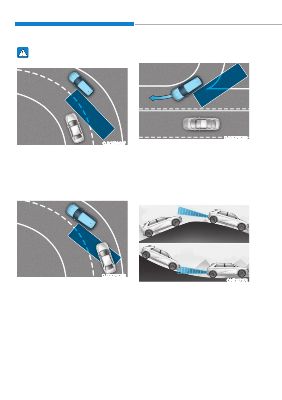
Driver Assistance System
7-44
WARNING
ś Driving on a curved road
OJX1079057
Blind-Spot Collision-Avoidance
Assist may not operate properly
when driving on a curved road. The
function may not detect the vehicle
in the next lane.
Always pay attention to road and
driving conditions while driving.
OJX1079058
Blind-Spot Collision-Avoidance
Assist may not operate properly
when driving on a curved road. The
function may recognize a vehicle in
the same lane.
Always pay attention to road and
driving conditions while driving.
ś Driving where the road is merging/
dividing
OJX1079059
Blind-Spot Collision-Avoidance
Assist may not operate properly
when driving where the road merges
or divides. The function may not
detect the vehicle in the next lane.
Always pay attention to road and
driving conditions while driving.
ś Driving on a sloped road
ONE1071171
Blind-Spot Collision-Avoidance Assist
may not operate properly when
driving on a slope. The function may
not detect the vehicle in the next
lane or may incorrectly detect the
ground or structure.
Always pay attention to road and
driving conditions while driving.
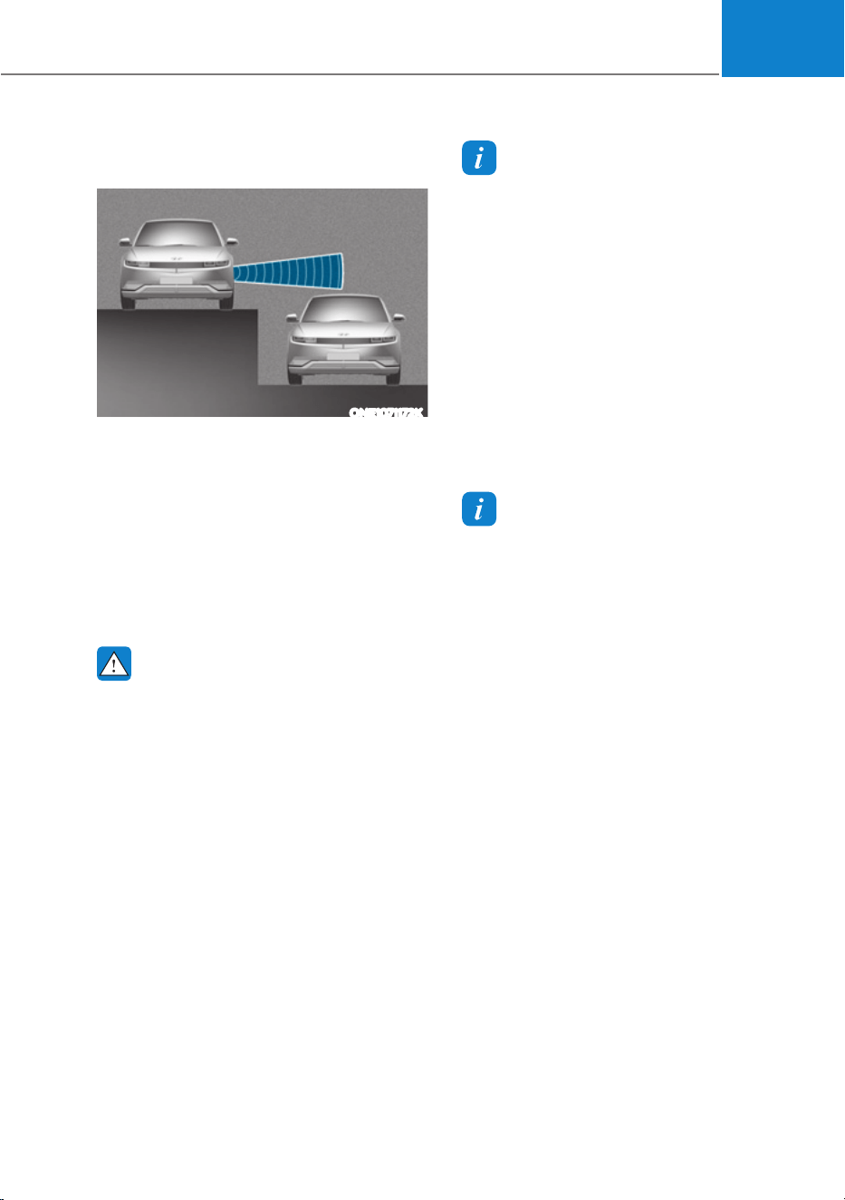
07
7-45
ś Driving where the heights of the
lanes are different
ONE1071172K
Blind-Spot Collision-Avoidance
Assist may not operate properly
when driving where the heights of
the lanes are different. The function
may not detect the vehicle on a
road with different lane heights
(underpass joining section, grade
separated intersections, etc.).
Always pay attention to road and
driving conditions while driving.
WARNING
ś When you are towing a trailer or
another vehicle, make sure that
you turn off Blind-Spot Collision-
Avoidance Assist.
ś Blind-Spot Collision-Avoidance
Assist may not operate properly if
interfered by strong electromagnetic
waves.
ś Blind-Spot Collision-Avoidance
Assist may not operate for 15 seconds
after the vehicle is started, or the
front view camera or rear corner
radars are initialized.
Information
This device complies with Part 15 of the
FCC rules.
Operation is subject to the following three
conditions:
1. This device may not cause harmful
interference, and
2. This device must accept any
interference received, including
interference that may cause undesired
operation of the device.
3. Changes or modifications not expressly
approved by the party responsible
for compliance could void the user's
authority to operate the device.
Information
Radio frequency radiation exposure
information:
This equipment complies with FCC
radiation exposure limits set forth for an
uncontrolled environment.
This equipment should be installed and
operated with minimum distance of 8 in.
(20 cm) between the radiator (antenna)
and your body.
This transmitter must not be co-located or
operating in conjunction with any other
antenna or transmitter.
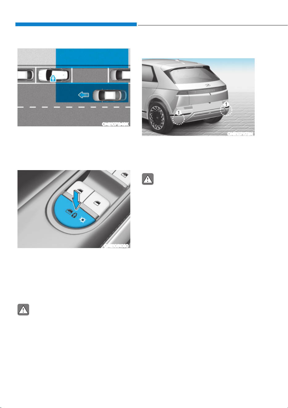
Driver Assistance System
7-46
6$)((;,7$66,67ǣ6($Ǥǣ,)(48,33('Ǥ
ONE1071249K
After the vehicle stops, when an
approaching vehicle from the rear area
is detected after a passenger opens the
door, Safe Exit Assist will warn the driver
with a warning message and an audible
warning to help prevent a collision.
ONE1051020
In addition, when the electronic child
safety lock button is in the LOCK position
and an approaching vehicle from the
rear area is detected, the electronic child
safety lock button will not unlock even if
the driver presses the button to prevent
the rear doors from opening.
CAUTION
Warning timing may vary depending on
the speed of the approaching vehicle.
Detecting sensor
ONE1071173N
[1] : Rear corner radar
Refer to the picture above for the
detailed location of the detecting
sensors.
CAUTION
For more details on the precautions of
the rear corner radars, refer to “Blind-
Spot Collision-Avoidance Assist (BCA)”
section in this chapter.

07
7-47
Safe Exit Assist Settings
Setting features
ONE1071197L
Safe Exit Assist
With the vehicle on, select ‘Driver
$VVLVWDQFHƟ%OLQG6SRW6DIHW\Ɵ6DIH([LW
Assist’ from the Settings menu to turn on
Safe Exit Assist and deselect to turn off
the function.
WARNING
The driver should always be aware of his
or her surroundings. If ‘Safe Exit Assist’
is deselected, Safe Exit Assist cannot
assist you.
Information
If the vehicle is restarted, Safe Exit Assist
will maintain the last setting.
ONE1071282N
Warning Timing
With the vehicle on, select ‘Driver
$VVLVWDQFHƟ:DUQLQJ7LPLQJŔIURPWKH
Settings menu to change the initial
warning activation time for Safe Exit
Assist.
When the vehicle is first delivered,
Warning Timing is set to ‘Normal’. If you
change the Warning Timing, the Warning
Timing of other Driver Assistance
systems may change.
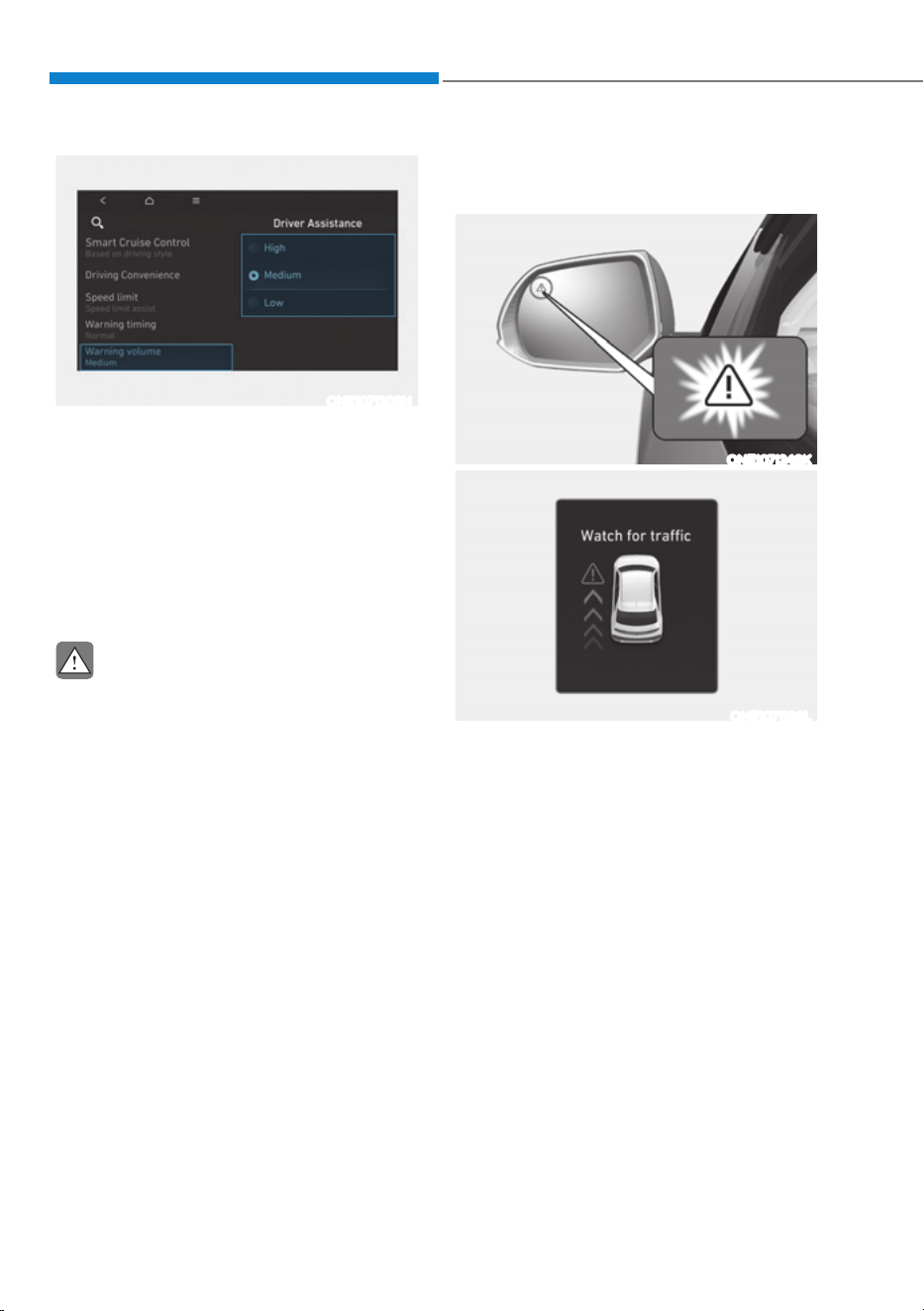
Driver Assistance System
7-48
ONE1071202N
Warning Volume
With the vehicle on, select ‘Driver
$VVLVWDQFHƟ:DUQLQJ9ROXPHŔIURPWKH
Settings menu to change the Warning
Volume to ‘High’, ‘Medium’ or ‘Low’ for
Safe Exit Assist.
If you change the warning volume,
the Warning Volume of other Driver
Assistance systems may change.
CAUTION
ś The setting of the Warning Timing
and Warning Volume applies to all
functions of the Safe Exit Assist.
ś Even though ‘Normal’ is selected
for Warning Timing, if a vehicle
approaches at high speed from the
rear, the warning may seem late.
ś Select ‘Late’ for Warning Timing
when traffic is light and driving
speed is slow.
Safe Exit Assist Operation
Warning and control
ONE1071248K
ONE1071198L
Collision warning when exiting vehicle
ś When an approaching vehicle from
the rear is detected at the moment a
door is opened, the ‘Watch for traffic’
warning message will appear on the
cluster, and an audible warning will
sound.
ś Safe Exit Assist will warn the driver
when your vehicle speed is below
2 mph (3 km/h), and the speed of the
approaching vehicle from the rear is
above 4 mph (6 km/h).

07
7-49
ONE1071199L
Safe Exit Assist linked with Electronic
child safety lock
ś When Electric child safety lock is
operating and an approaching vehicle
from the rear area is detected, the rear
doors cannot be unlocked even if the
driver tries to unlock the rear doors
using the electronic child safety lock
button. The warning light on the side
view mirror will blink and the ‘Check
surroundings then try again’ warning
message will appear on the cluster.
ś Safe Exit Assist will warn the driver
when vehicle speed is below 2 mph
(3 km/h) and the speed of the
approaching vehicle from the rear is
above 4 mph (6 km/h).
ś For more details on electric child
safety lock button, refer to “Electronic
Child Safety Lock” section in chapter
5.
CAUTION
If the driver presses the electronic child
lock button again within 10 seconds
after the warning message appears,
Safe Exit Assist judges that the driver
has unlocked the doors acknowledging
the rear status. The electronic child
safety lock will turn off (button
indicator OFF) and the rear doors will
unlock. Always check the surroundings
before turning off the electronic child
safety lock button.
Information
If a rear door is opened from the outside,
it will open regardless of Safe Exit Assist
operation.
WARNING
Take the following precautions when
using Safe Exit Assist:
ś For your safety, change the Settings
after parking the vehicle at a safe
location.
ś If any other system’s warning
message is displayed or audible
warning is generated, Safe Exit
Assist warning message may not be
displayed and audible warning may
not be generated.
ś You may not hear the warning sound
of Safe Exit Assist if the surrounding
is noisy.
ś Safe Exit Assist does not operate in
all situations or cannot prevent all
collisions.
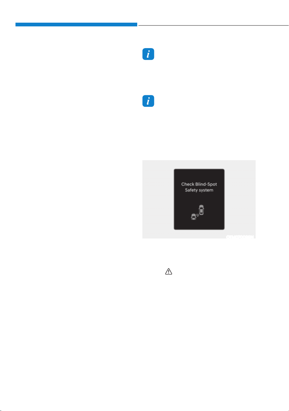
Driver Assistance System
7-50
ś Safe Exit Assist may warn the driver
late or may not warn the driver
depending on the road and driving
conditions. Always check vehicle
surroundings.
ś The driver and passengers are
responsible for accidents that occurs
while exiting the vehicle. Always
check the surroundings before you
exit the vehicle.
ś Never deliberately operate Safe Exit
Assist. Doing so may lead to serious
injury or death.
ś Safe Exit Assist does not operate if
there is a problem with Blind-Spot
Collision-Avoidance Assist. The
warning message of Blind-Spot
Collision-Avoidance Assist will
appear when:
- Blind-Spot Collision-Avoidance
Assist sensor or the sensor
surrounding is polluted or covered
- Blind-Spot Collision-Avoidance
Assist fails to warn passengers or
falsely warn passengers
Information
After the vehicle is turned off, Safe Exit
Assist operates approximately for 3
minutes, but turns off immediately if the
doors are locked.
Information
The images or colors may be displayed
differently depending on the specifications
of the instrument panel or theme.
Safe Exit Assist Malfunction and
Limitations
Safe Exit Assist malfunction
OTM070099N
When Safe Exit Assist is not working
properly, the ‘Check Blind-Spot Safety
system’ warning message will appear on
the cluster for several seconds, and the
master (
) warning light will illuminate
on the cluster. If it occurs, have the
vehicle be inspected by an authorized
HYUNDAI dealer.
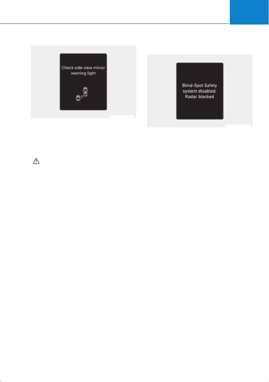
07
7-51
OTM070100N
When the side view mirror warning light
is not working properly, the ‘Check side
view mirror warning light’ (or ‘Check
outside mirror warning icon’) warning
message will appear on the cluster
for several seconds, and the master
(
) warning light will illuminate on the
cluster. If it occurs, have the vehicle be
inspected by an authorized HYUNDAI
dealer.
Safe Exit Assist disabled
OTM070098N
When the rear bumper around the rear
corner radar or sensor is covered with
foreign material, such as snow or rain,
or installing a trailer or carrier, it can
reduce the detecting performance and
temporarily limit or disable Safe Exit
Assist.
If this occurs, the ‘Blind-Spot Safety
system disabled. Radar blocked’ warning
message will appear on the cluster.
Safe Exit Assist will operate properly
when such foreign material or trailer,
etc., is removed, and then the vehicle is
restarted.
If Safe Exit Assist does not operate
properly after it is removed, have the
vehicle be inspected by an authorized
HYUNDAI dealer.

Driver Assistance System
7-52
WARNING
ś Even though the warning message
does not appear on the cluster, Safe
Exit Assist may not properly operate.
ś Safe Exit Assist may not properly
operate in an area (for example,
open terrain) where any objects are
not detected right after the vehicle
is turned on, or when the detecting
sensor is blocked with foreign
material right after the vehicle is
turned on.
CAUTION
Turn off Safe Exit Assist to install or
remove a trailer, carrier, or another
attachment. Turn on Safe Exit Assist
when finished.
Limitations of Safe Exit Assist
Safe Exit Assist may not operate properly,
or it may operate unexpectedly under the
following circumstances:
ś Getting out of the vehicle where trees
or grass are overgrown
ś Getting out of the vehicle where the
road is wet
ś The approaching vehicle is very fast or
very slow
Information
For more details on the limitations of the
rear corner radar, refer to “Blind- Spot
Collision-Avoidance Assist (BCA)” section
in this chapter.
WARNING
ś Safe Exit Assist may not operate
properly if interfered by strong
electromagnetic waves.
ś Safe Exit Assist may not operate
for 3 seconds after the vehicle is
started, or the rear corner radars are
initialized.
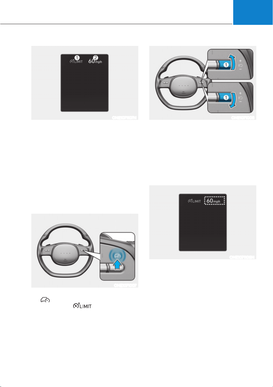
07
7-53
ONE1071107N
(1) Speed Limit indicator
(2) Set speed
You can set the speed limit when you do
not want to drive over a specific speed.
If you drive over the preset speed limit,
Manual Speed Limit Assist operates
(set speed limit will blink and chime will
sound) until the vehicle speed returns
within the speed limit.
Manual Speed Limit Assist
Operation
Setting speed limit
ONE1071007
1. Press and hold Driving Assist
(
) button at the desired speed. The
Speed Limit (
) indicator will
illuminate on the cluster.
ONE1071008
2. Push the + switch (1) up or - switch
(1) down, and release it at the desired
speed.
Push the + switch (1) up or - switch
(1) down and hold it. The speed will
increase or decrease to the nearest
multiple of ten (multiple of five in
mph) at first, and then increase or
decrease by 5 mph (10 km/h).
ONE1071108N
3. The set speed limit will be displayed
on the cluster.
If you would like to drive over the
preset speed limit, depress the
accelerator pedal beyond the pressure
point to activate the kickdown
mechanism.
The set speed limit will blink and
chime will sound until you return the
vehicle speed within the speed limit.
0$18$/63(('/,0,7$66,67ǣ06/$Ǥ
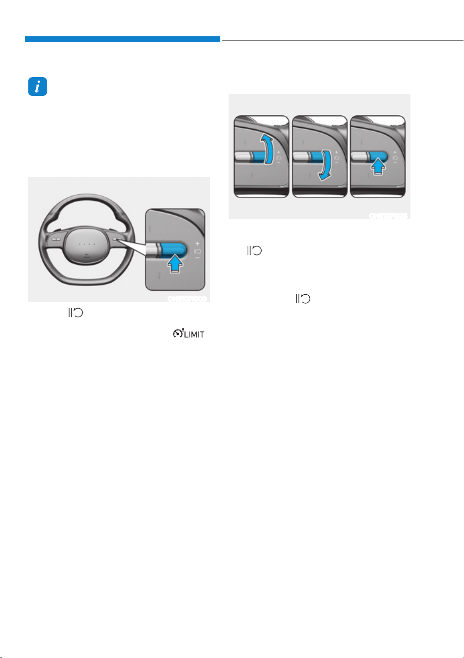
Driver Assistance System
7-54
Information
When the accelerator pedal is not
depressed beyond the pressure point,
vehicle speed will maintain within the
speed limit.
Temporarily pausing Manual Speed
Limit Assist
ONE1071009
Push the switch to temporarily pause
the set speed limit. The set speed limit
will turn off but the Speed Limit (
)
indicator will stay on.
Resuming Manual Speed Limit Assist
ONE1071023
To resume Manual Speed Limit Assist
after the function was paused, push the
+, -,
switch.
If you push the + switch (1) up or – switch
(1) down, vehicle speed will be set to the
current speed on the cluster.
If you push the
switch, vehicle speed
will resume to the preset speed.
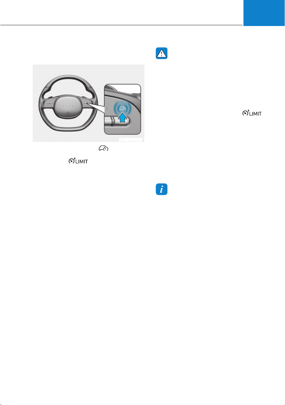
07
7-55
Turning off Manual Speed Limit
Assist
ONE1071007
Press the Driving Assist ( ) button to
turn Manual Speed Limit Assist off. The
Speed Limit (
) indicator will go
off.
WARNING
Take the following precautions when
using Manual Speed Limit Assist:
ś Always set the vehicle speed under
the speed limit in your country.
ś Keep Manual Speed Limit Assist off
when the function is not in use, to
avoid inadvertently setting a speed.
Check that the Speed Limit (
)
indicator is off.
ś Manual Speed Limit Assist does
not substitute for proper and safe
driving. It is the responsibility of
the driver to always drive safely
and should always be aware of
unexpected and sudden situations
from occurring. Pay attention to the
road conditions at all times.
Information
The images or colors may be displayed
differently depending on the specifications
of the instrument panel or theme.
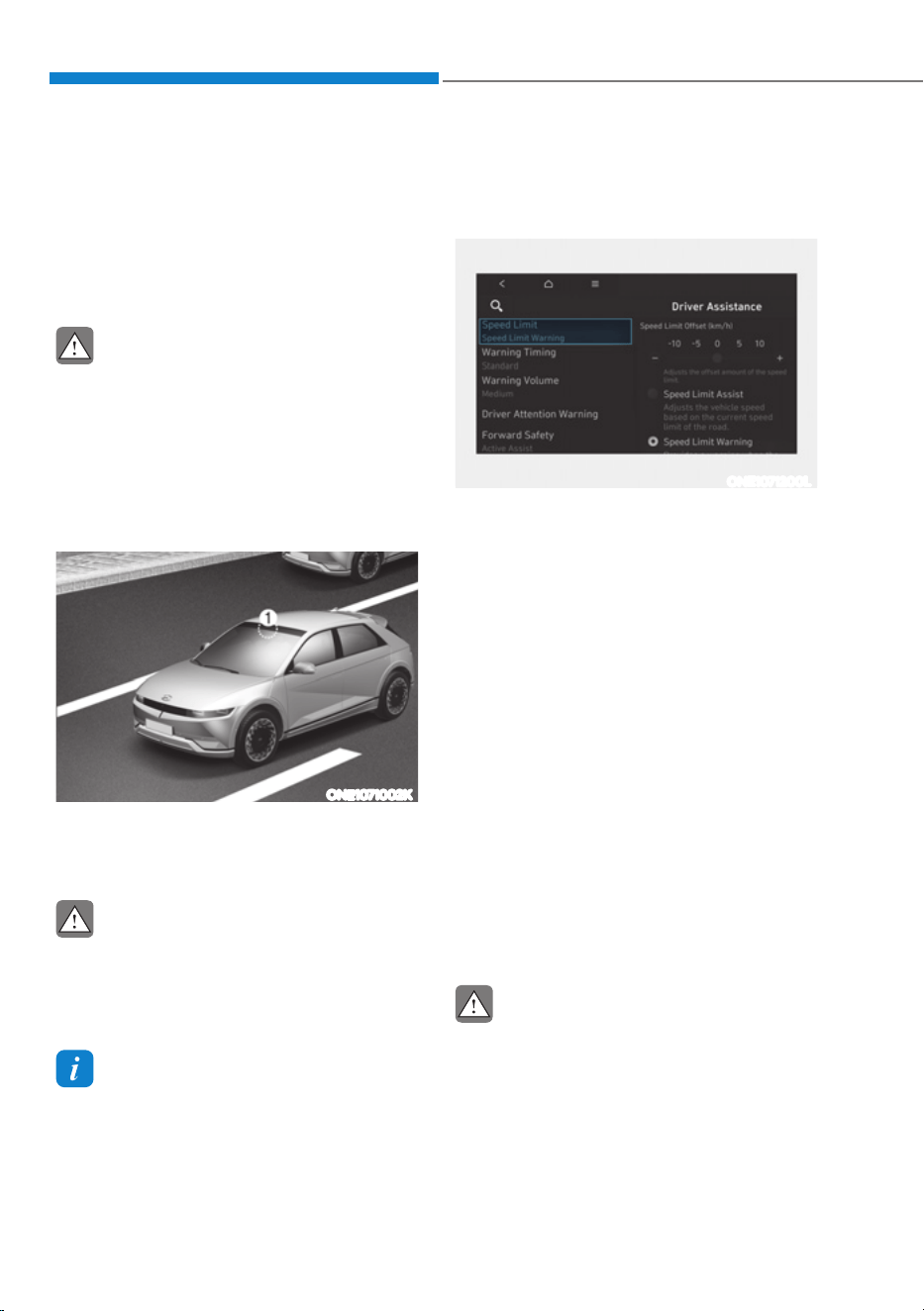
Driver Assistance System
7-56
Intelligent Speed Limit Assist uses
information from the detected road sign
and navigation system to inform the
driver of the speed limit of the current
road. Also, Intelligent Speed Limit Assist
helps the driver to maintain within the
speed limit of the road.
CAUTION
ś Intelligent Speed Limit Assist may
not operate properly if the function is
used in other countries.
ś Update your navigation regularly to
ensure that Intelligent Speed Limit
Assist works properly.
Detecting sensor
ONE1071002K
[1]: Front view camera
Refer to the picture above for the
detailed location of the detecting sensor.
CAUTION
For more details on the precautions
of the front view camera, refer to
“Forward Collision-Avoidance Assist
(FCA)” section in this chapter.
Information
If the navigation system is available, the
information from the navigation system is
used along with the road sign information
detected by the front view camera.
Intelligent Speed Limit Assist
Settings
Setting features
ONE1071200L
Speed Limit
With the vehicle on, select or deselect
œ'ULYHU$VVLVWDQFHƟ6SHHG/LPLWŔIURP
the Settings menu to set whether or not
to use each function.
- If ‘Speed Limit Assist’ is selected,
Intelligent Speed Limit Assist will
inform the driver of speed limit. In
addition, Intelligent Speed Limit Assist
will inform the driver to change set
speed of Manual Speed Limit Assist
and/or Smart Cruise Control to help
the driver stay within the speed limit.
- If ‘Speed Limit Warning’ is selected,
Intelligent Speed Limit Assist will
inform the driver of speed limit. In
addition, Intelligent Speed Limit Assist
will warn the driver when the vehicle
is driven faster than the speed limit.
- If ‘Off’ is selected, Intelligent Speed
Limit Assist will turn off.
CAUTION
If ‘Speed Limit Warning’ is selected,
Intelligent Speed Limit Assist will not
inform the driver to adjust set speed.
,17(//,*(1763(('/,0,7$66,67ǣ,6/$Ǥǣ,)(48,33('Ǥ

07
7-57
ONE1071201L
Speed Limit Offset
With the vehicle on, when ‘Driver
$VVLVWDQFHƟ6SHHG/LPLWƟ6SHHG/LPLW
Offset’ is selected, the Speed Limit Offset
can be changed. Speed Limit Warning
and Speed Limit Assist will operate by
applying the Speed Limit Offset setting
to the detected speed limit.
WARNING
ś For your safety, change the Settings
after parking the vehicle at a safe
location.
ś Speed Limit Assist function operates
based on the Offset setting added
to the speed limit. If you want to
change the set speed according to
the speed limit, adjust the offset to
‘0’.
ś Speed Limit Warning function warns
the driver when driving speed
exceeds the speed at which the set
Offset is added to speed limit. If you
want Speed Limit Warning to warn
you immediately when the driving
speed exceeds the speed limit,
adjust the offset to ‘0’.
Information
The setting of 'Speed Offset' is not
reflected in Navigation-based Smart
Cruise Control (NSCC).
Intelligent Speed Limit Assist
Operation
Warning and control
Intelligent Speed Limit Assist will warn
and control the vehicle by ‘Displaying
speed limit’, ‘Warning overspeed’ and
‘Changing set speed’.
Information
Intelligent Speed Limit Assist warning and
control are described based on the Offset
adjust to '0'. For details on Offset setting,
refer to the “Intelligent Speed Limit Assist
Settings”.
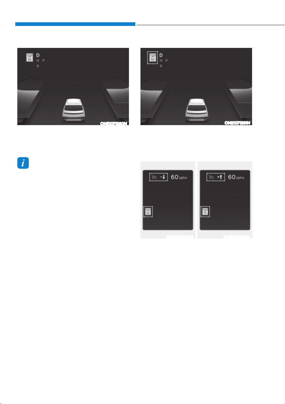
Driver Assistance System
7-58
ONE1071260N
Displaying speed limit
Speed limit information is displayed on
the instrument cluster.
Information
ś If speed limit information of the road
cannot be recognized, '---' sign will be
displayed. Please refer to "Limitations
of Intelligent Speed Limit Assist" if the
road signs are difficult to recognize.
ś Supplementary sign displayed under
the speed limit or overtaking restriction
sign means the conditions under which
the signs must be followed. If the
supplementary sign is not recognized, it
will be displayed as blank.
ONE1071261N
Warning overspeed
When driving at a speed higher than the
displayed speed limit, the speed limit is
displayed in red.
ONE1071084N ONE1071085N
Changing set speed
If the speed limit of the road changes
during the operation of Manual Speed
Limit Assist or Smart Cruise Control, an
arrow in the direction of up or down is
displayed to inform the driver that the set
speed needs to be changed. At this time,
the driver can change the set speed
according to the speed limit by using the
+ or – switch on the steering wheel.
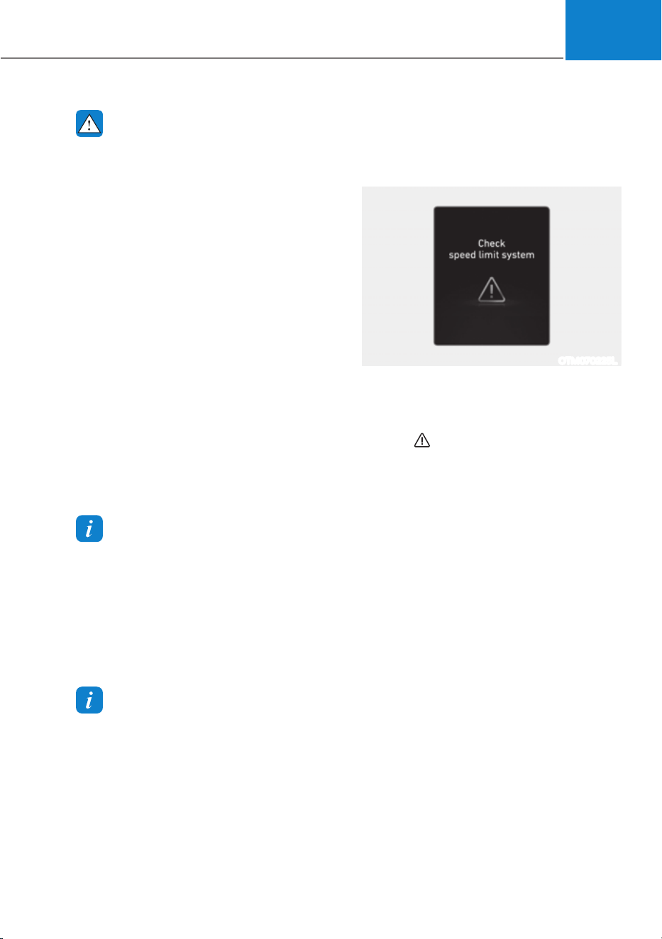
07
7-59
WARNING
ś If the Offset is adjusted over ‘0’, the
set speed will change to a higher
speed than the speed limit of the
road. If you want to drive below the
speed limit, adjust the Offset under
'0' or use the – switch on the steering
wheel to lower the set speed.
ś Even after changing the set speed
according to the speed limit of the
road, the vehicle can still be driven
over the speed limit. If necessary,
depress the brake pedal to reduce
your driving speed.
ś If the speed limit of the road is under
20 mph (30 km/h), the set speed
change function will not work.
ś Intelligent Speed Limit Assist
operates using the speed unit in the
instrument cluster set by the driver.
If the speed unit is set to a unit other
than the speed unit used in your
country, Intelligent Speed Limit
Assist may not operate properly.
Information
ś For more details on Manual Speed
Limit Assist operation, refer to
“Manual Speed Limit Assist (MSLA)”
section in this chapter.
ś For more details on Smart Cruise
Control operation, refer to “Smart
Cruise Control (SCC)” section in this
chapter.
Information
The images or colors may be displayed
differently depending on the specifications
of the instrument panel or theme.
Intelligent Speed Limit Assist
Malfunction and Limitations
Intelligent Speed Limit Assist
malfunction
OTM070225L
When Intelligent Speed Limit Assist is not
working properly, the ‘Check speed limit
system’ warning message will appear on
the cluster for several seconds, and the
master (
) warning light will illuminate
on the cluster. If this occurs, have the
vehicle be inspected by an authorized
HYUNDAI dealer.

Driver Assistance System
7-60
Intelligent Speed Limit Assist
disabled
OIK070145L
When the front windshield where the
front view camera is located is covered
with foreign material, such as snow
or rain, it can reduce the detecting
performance and temporarily limit or
disable Intelligent Speed Limit Assist.
If this occurs, the ‘Speed limit system
disabled. Camera obscured’ warning
message will appear on the cluster.
Intelligent Speed Limit Assist will operate
properly when snow, rain or foreign
material is removed.
If Intelligent Speed Limit Assist does
not operate properly after it is removed,
have the vehicle be inspected by an
authorized HYUNDAI dealer.
WARNING
ś Even though the warning message or
warning light does not appear on the
cluster, Intelligent Speed Limit Assist
may not operate properly.
ś If the detecting sensor is
contaminated immediately after
starting the vehicle, Intelligent
Speed Limit Assist may not operate
properly.
Limitations of Intelligent Speed
Limit Assist
Intelligent Speed Limit Assist may not
operate properly, or it may operate
unexpectedly under the following
circumstances:
ś The road sign is contaminated or
indistinguishable
- The road sign is difficult to see due
to bad weather, such as rain, snow,
fog, etc.
- The road sign is not clear or
damaged
- The road sign is partially obscured
by surrounding objects or shadow
- A road sign near the road you are
driving is detected
ś The road signs do not conform to the
standard
- The text or picture on the road sign
is different from the standard
- The road sign is installed between
the main line and the exit road or
between diverging roads
- There is no conditional road signs
on the road sign located on the exit
road
- A sign is attached to another vehicle

07
7-61
ś The distance between the vehicle and
the road signs is too far
ś The vehicle encounters illuminant
road signs
ś Intelligent Speed Limit Assist
incorrectly recognizes numbers in the
street signals or other signs as the
speed limit
ś The minimum speed limit sign is on
the road
ś The brightness changes suddenly, for
example when entering or exiting a
tunnel or passing under a bridge
ś Headlamps are not used or the
brightness of the headlamps are weak
at night or in the tunnel
ś Road signs are difficult to recognize
due to the reflection of sunlight, street
lights, or oncoming vehicles
ś The navigation information or GPS
information contain errors.
ś The driver does not follow the guide
of the navigation.
ś The driver is driving a new road that is
not in the navigation system yet.
ś The field of view of the front view
camera is obstructed by sun glare
ś Driving on a road that is sharply
curved or continuously curved
ś Driving through speed bumps, or
driving up and down or left to right on
steep inclines
ś The vehicle is shaking heavily
ś There is an error in the navigation map
information or GPS information
ś The driver is not driving along the
navigation guide route
ś Driving on a newly opened road
Information
For more details on the limitations of the
front view camera, refer to “Forward
Collision-Avoidance Assist (FCA)” section
in this chapter.
WARNING
ś Intelligent Speed Limit Assist is a
supplemental function that helps the
driver to comply with the speed limit
on the road, and may not display the
correct speed limit or control the
driving speed properly.
ś Always set the vehicle speed to the
speed limit in your country.
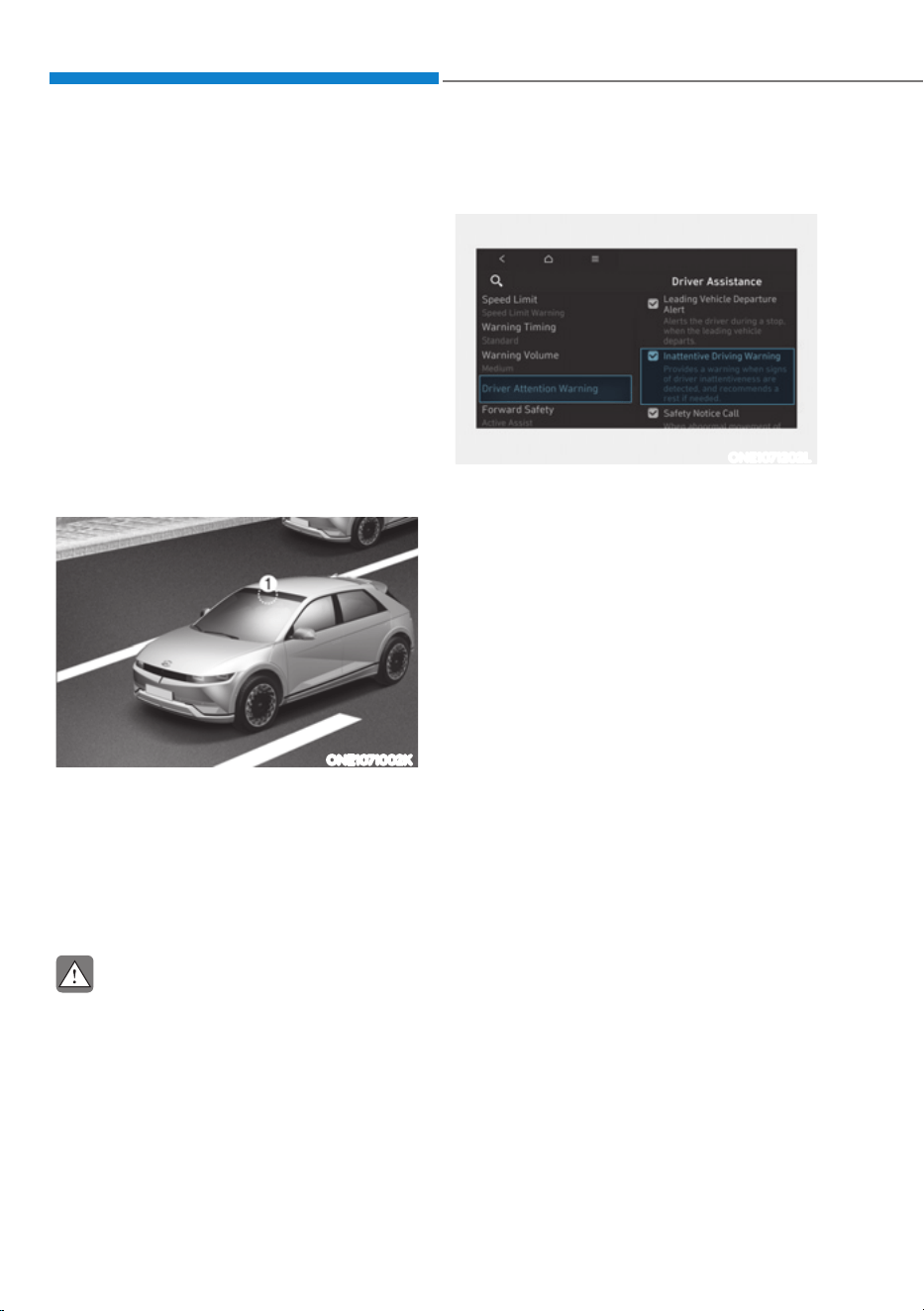
Driver Assistance System
7-62
Basic function
Driver Attention Warning can help
determine the driver's attention level
by analyzing driving pattern and driving
time while vehicle is driven. Driver
Attention Warning will recommend a
break when the driver’s attention level
falls below a certain level.
Leading vehicle departure alert
function
Leading Vehicle Departure Alert function
will inform the driver when a detected
vehicle in front departs from a stop.
Detecting sensor
ONE1071002K
[1]: Front view camera
The front view camera is used as a
detecting sensor to help detect driving
patterns and front vehicle departure
while vehicle is being driven.
Refer to the picture above for the
detailed location of the detecting sensor.
CAUTION
ś Always keep the front view camera in
good condition to maintain optimal
performance of Driver Attention
Warning.
ś For more details on the precautions
of the front view camera, refer to
“Forward Collision-Avoidance Assist
(FCA)” section in this chapter.
Driver Attention Warning Settings
Setting features
ONE1071202L
Driver Attention Warning
With the vehicle on, select or deselect
œ'ULYHU$VVLVWDQFHƟ'ULYHU$WWHQWLRQ
Warning’ from the Settings menu to set
whether to use each function.
- If ‘Inattentive Driving Warning’ is
selected, Driver Attention Warning will
inform the driver the driver’s attention
level and will recommend taking a
break when the level falls below a
certain level.
'5,9(5$77(17,21:$51,1*ǣ'$:Ǥǣ,)(48,33('Ǥ
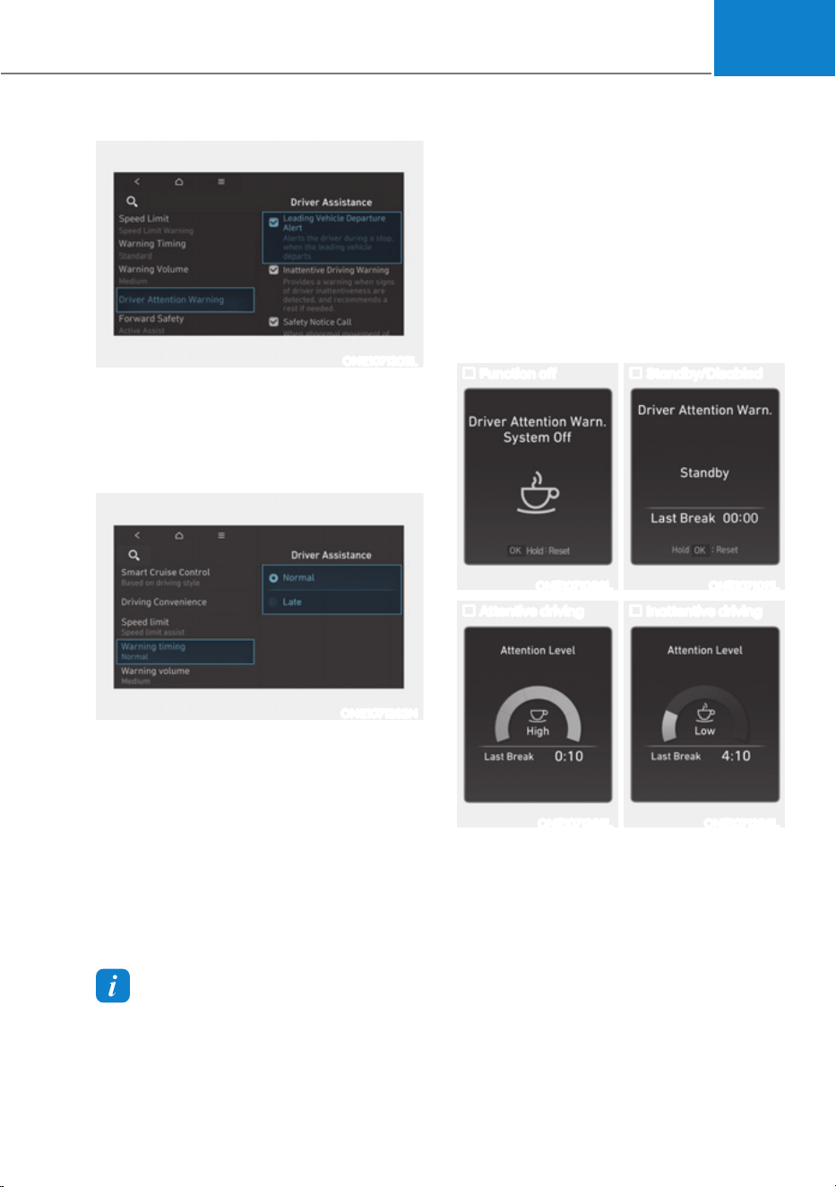
07
7-63
ONE1071203L
Leading Vehicle Departure Alert
- If ‘Leading Vehicle Departure Alert’ is
selected, the function will inform the
driver when the front vehicle departs
from a stop.
ONE1071282N
Warning Timing
With the vehicle on, select ‘Driver
$VVLVWDQFHƟ:DUQLQJ7LPLQJŔIURPWKH
Settings menu to change the initial
warning activation time for Driver
Attention Warning.
When the vehicle is first delivered,
Warning Timing is set to ‘Normal’. If you
change the Warning Timing, the Warning
Timing of other Driver Assistance
systems may change.
Information
If the vehicle is restarted, Warning Timing
will maintain the last setting.
Driver Attention Warning
Operation
Basic function
Display and warning
The basic function of Driver Attention
Warning is to inform the driver the
‘Attention Level’ and to warn the driver
‘Consider taking a break’.
Attention Level
Function off Standby/Disabled
ONE1071089L ONE1071011L
Attentive driving Inattentive driving
ONE1071285L ONE1071286L
ś The driver can monitor his/her driving
conditions on the cluster.
- When the ‘Inattentive Driving
Warning’ is deselected from the
Settings menu, ‘System Off’ is
displayed.
- Driver Attention Warning will
operate when vehicle speed is
between 0
- 130 mph (0 - 210 km/h).
- When vehicle speed is not within
the operating speed, the message
‘Standby’ will be displayed.
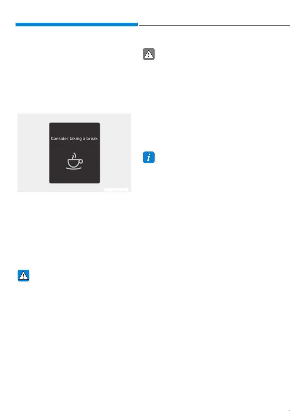
Driver Assistance System
7-64
ś The driver’s attention level is displayed
on the scale of 1 to 5. The lower the
level is, the more inattentive the driver
is.
ś The level decreases when the driver
does not take a break for a certain
period of time.
Taking a break
ONE1071014L
ś The ‘Consider taking a break’ message
will appear on the cluster and an
audible warning will sound to suggest
that the driver take a break, when the
driver’s attention level is below 1.
ś Driver Attention Warning will not
suggest a break when the total driving
time is shorter than 10 minutes or 10
minutes has not passed after the last
break was suggested.
WARNING
For your safety, change the Settings
after parking the vehicle at a safe
location.
CAUTION
ś Driver Attention Warning may
suggest a break depending on the
driver’s driving pattern or habits,
even if the driver doesn’t feel fatigue.
ś Driver Attention Warning is a
supplemental function and may not
be able to determine whether the
driver is inattentive.
ś The driver who feels fatigued should
take a break at a safe location, even
though there is no break suggestion
by Driver Attention Warning.
Information
ś For more details on setting the
functions in the infotainment system,
refer to “Vehicle Settings” section in
chapter 4.
ś Driver Attention Warning will reset the
last break time to 00:00 in the following
situations:
- The vehicle is turned off
- The driver unfastens the seat belt
and opens the driver’s door
- The vehicle is stopped for more than
10 minutes
ś When the driver resets Driver Attention
Warning, the last break time is set to
00:00 and the driver’s attention level is
set to High.
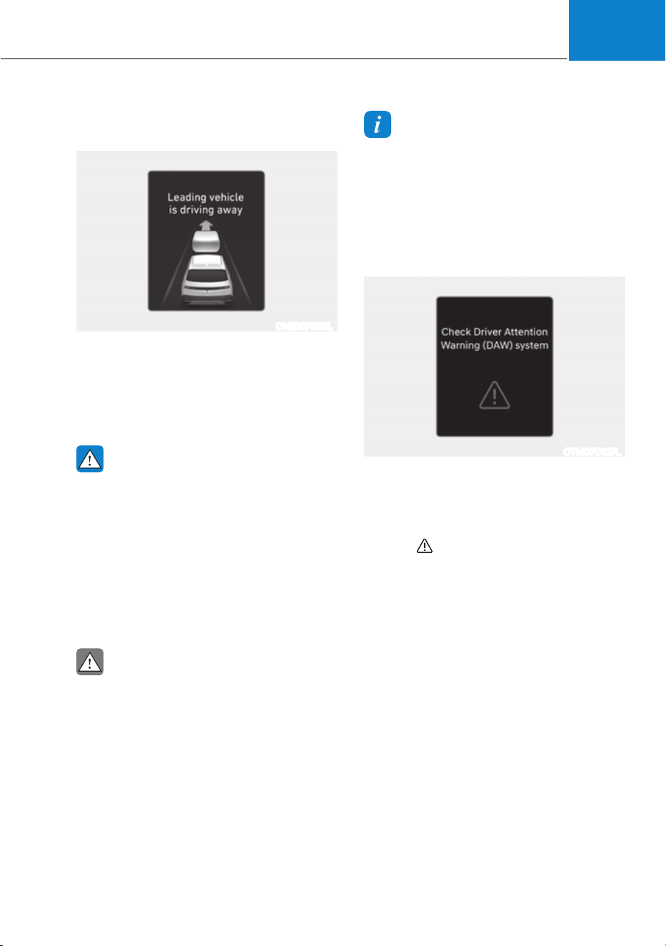
07
7-65
Leading Vehicle Departure Alert
function
ONE1071133L
When a detected vehicle in front departs
from a stop, Leading Vehicle Departure
Alert will inform the driver by displaying
the ‘Leading vehicle is driving away’
message on the cluster and an audible
warning will sound.
WARNING
ś If any other system’s warning
message is displayed or audible
warning is generated, Leading
Vehicle Departure Alert's warning
message may not be displayed
and audible warning may not be
generated.
ś The driver should hold the
responsibility to safely drive and
control the vehicle.
CAUTION
ś Leading Vehicle Departure Alert is a
supplemental function and may not
alert the driver whenever the front
vehicle departs from a stop.
ś Always check the front of the
vehicle and road conditions before
departure.
Information
The images or colors may be displayed
differently depending on the specifications
of the instrument panel or theme.
Driver Attention Warning
Malfunction and Limitations
Driver Attention Warning
malfunction
OTM070107L
When Driver Attention Warning is not
working properly, the ‘Check Driver
Attention Warning (DAW) system’
warning message will appear on the
cluster for several seconds, and the
master (
) warning light will illuminate
on the cluster. If this occurs, have the
vehicle be inspected by an authorized
HYUNDAI dealer.
Limitations of Driver Attention
Warning
Driver Attention Warning may not work
properly in the following situations:
ś The vehicle is driven violently
ś The vehicle intentionally crosses over
lanes frequently
ś The vehicle is controlled by Driver
Assistance system, such as Lane
Keeping Assist
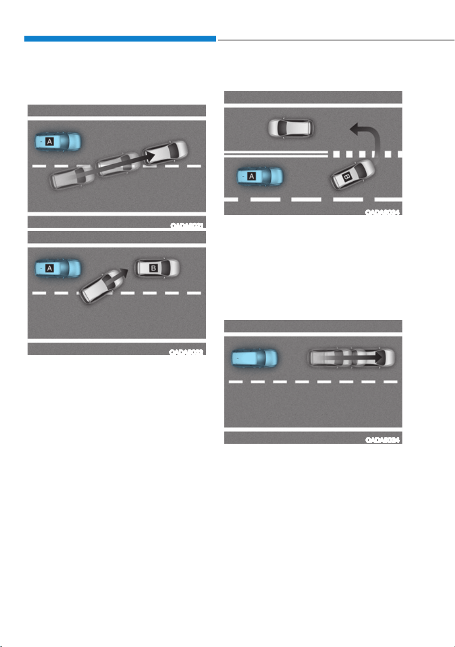
Driver Assistance System
7-66
Leading vehicle departure alert function
ś When the vehicle cuts in
OADAS021
OADAS022
[A] : Your vehicle, [B] : Front vehicle
If a vehicle cuts in front of your
vehicle, Leading Departure Alert may
not operate properly.
ś When the vehicle ahead sharply steers
OADAS034
[A] : Your vehicle, [B] : Front vehicle
If the vehicle in front makes a sharp
turn, such as to turn left or right or
make a U- turn, etc., Leading Vehicle
Departure Alert may not operate
properly.
ś When the vehicle ahead abruptly
departures
OADAS024
If the vehicle in front abruptly
departures, Leading Vehicle Departure
Alert may not operate properly.
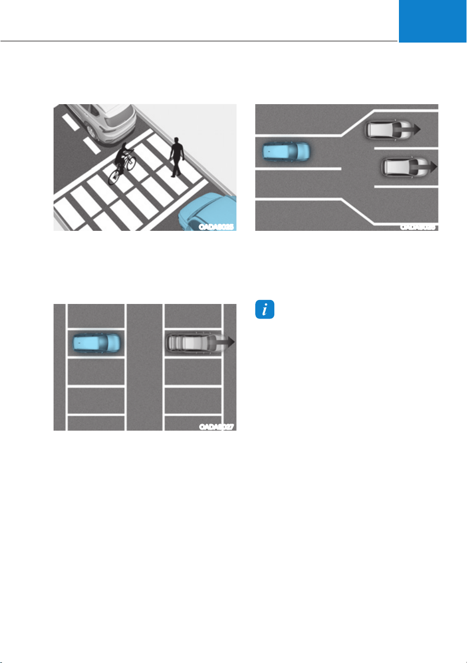
07
7-67
ś When a pedestrian or bicycle is
between you and the vehicle ahead
OADAS025
If there is a pedestrian(s) or bicycle(s)
in between you and the vehicle in
front, Leading Vehicle Departure Alert
may not operate properly.
ś When in a parking lot
OADAS027
If a vehicle parked in front drives away
from you, Leading Vehicle Departure
Alert may alert you that the parked
vehicle is driving away.
ś When driving at a tollgate or
intersection, etc.
OADAS026
If you pass a tollgate or intersection
with lots of vehicles or you drive
where lanes are merged or divided
frequently, Leading Vehicle Departure
Alert may not operate properly.
Information
For more details on the precautions of
the front view camera, refer to “Forward
Collision-Avoidance Assist (FCA)” section
in this chapter.

Driver Assistance System
7-68
Left side Right side
ONE1071091L ONE1071091JP
Blind-Spot View Monitor displays the
rear blind spot area of the vehicle in the
cluster when the turn signal is turned on
to help safely change lanes.
Detecting sensor
ONE1071017K
[1], [2]: Surround-side view camera
(camera located at bottom of the mirror)
Refer to the picture above for the
detailed location of the detecting
sensors.
Blind-Spot View Monitor
Settings
Setting features
Blind-Spot View
With the vehicle on, select ‘Driver
$VVLVWDQFHƟ%OLQG6SRW6DIHW\Ɵ%OLQG
Spot View’ from the Settings menu to
turn on Blind-Spot View Monitor and
deselect to turn off the function.
Blind-Spot View Monitor
Operation
Operating switch
ONE1051062
Turn signal lever
Blind-Spot View Monitor will turn on and
off when the turn signal is turned on and
off.
%/,1'ǘ63279,(:021,725ǣ%90Ǥǣ,)(48,33('Ǥ

07
7-69
Blind-Spot View Monitor
Operating conditions
ś \When the turn signal turns off, the
image on the instrument cluster will
turn off.
ś When the hazard warning flasher
is on, Blind-Spot View Monitor will
turn off, regardless of the turn signal
status.
ś When other important warning is
displayed on the instrument cluster,
Blind-Spot View Monitor may turn off.
Blind-Spot View Monitor
Malfunction
When Blind-Spot View Monitor is not
working properly, or the cluster display
flickers, or the camera image does not
display properly, have the vehicle be
inspected by an authorized HYUNDAI
dealer.
WARNING
ś The image shown on the cluster may
differ from the actual distance of the
object. Make sure to directly check
the vehicle's surroundings for safety.
ś Always keep the camera lens clean.
If the lens is covered with foreign
material, it may adversely affect
camera performance and Blind-
Spot View Monitor may not operate
properly.
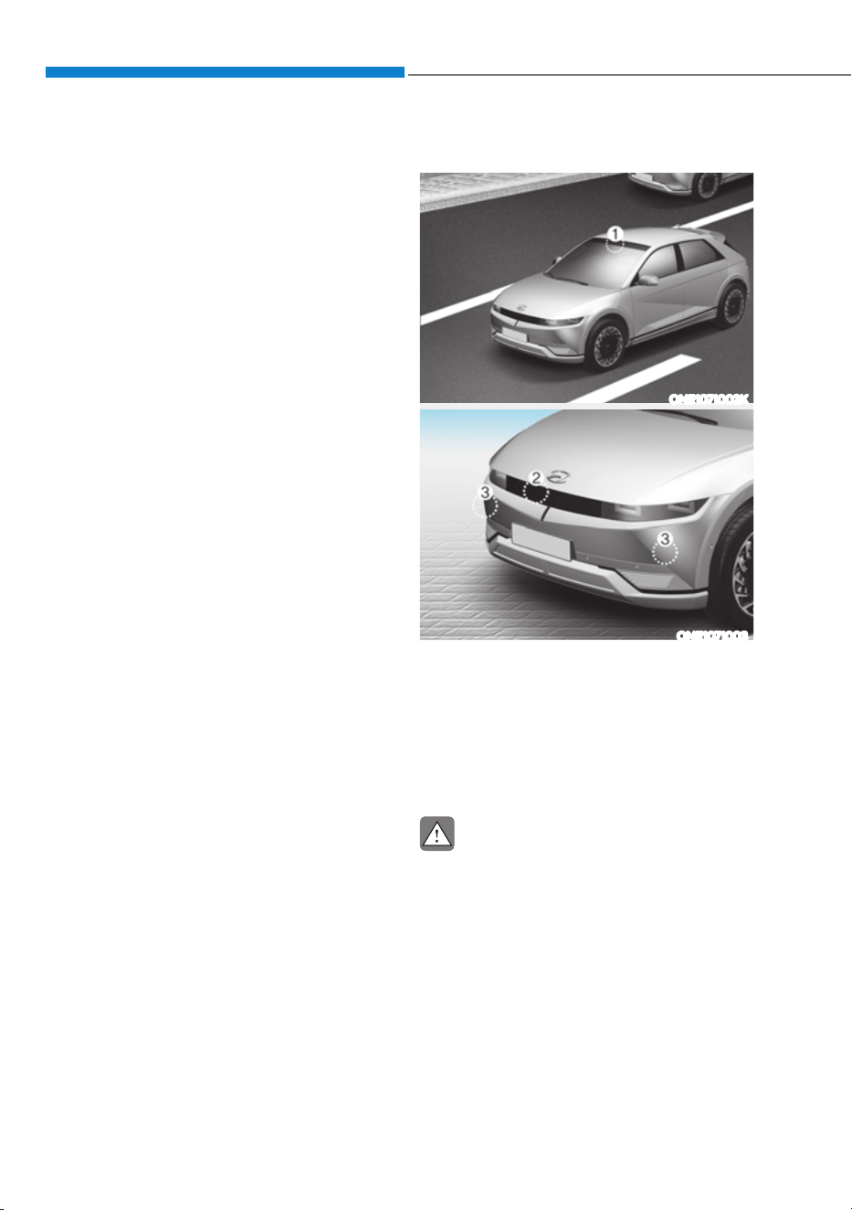
Driver Assistance System
7-70
60$57&58,6(&21752/ǣ6&&Ǥ
Smart Cruise Control is designed to
help detect the vehicle ahead and
help maintain the desired speed and
minimum distance between the vehicle
ahead.
Overtaking Acceleration Assist
While Smart Cruise Control is operating,
if the function judges that the driver is
determined to overtake the vehicle in
front, acceleration will be assisted.
Based on Driving Style (if equipped)
Smart Cruise Control will operate based
on the driver’s driving style, such as
inter-vehicle distance, acceleration,
reaction speed.
Detecting sensor
ONE1071002K
ONE1071003
[1]: Front view camera, [2]: Front radar,
[3] : Front corner radar
The front view camera and front radar
are used as a detecting sensor to detect
front vehicles.
Refer to the picture above for the
detailed location of the detecting sensor.
CAUTION
Always keep the front view camera
and front radar in good condition to
maintain optimal performance of Smart
Cruise Control.
For more details on the precautions of
the front view camera and front radar,
refer to “Forward Collision-Avoidance
Assist (FCA)” section in this chapter.
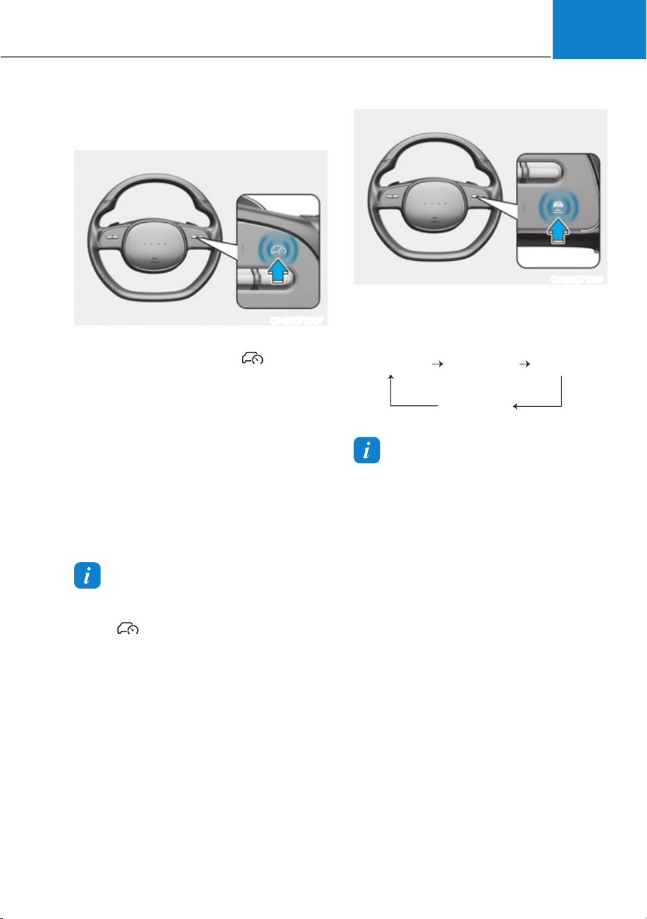
07
7-71
Smart Cruise Control Settings
Setting features
ONE1071007
Turning on Smart Cruise Control
ś Press the Driving Assist ( ) button
to turn on Smart Cruise Control. The
speed will be set to the current speed
on the cluster.
ś If there is no vehicle in front of you,
the set speed will be maintained, but
if there is a vehicle in front of you,
the speed may decrease to maintain
the distance to the vehicle ahead. If
the vehicle ahead accelerates, your
vehicle will travel at a steady cruising
speed after accelerating to the set
speed.
Information
If your vehicle speed is between 0 - 20 mph
(0
- 30 km/h) when you press the Driving
Assist (
) button, the Smart Cruise
Control speed will be set to 20 mph (30
km/h).
ONE1071019
Setting vehicle distance
Each time the button is pressed, the
headway changes as follows:
Distance 4 Distance 3
Distance 1
Distance 2
Information
ś If you drive at 56 mph (90 km/h), the
distance is maintained as follows:
Distance 4 -
approximately 172 ft. (52.5 m)
Distance 3 -
approximately 130 ft. (40 m)
Distance 2 -
approximately 106 ft. (32.5 m)
Distance 1 -
approximately 82 ft. (25 m)
ś The distance is set to the last set
distance when the vehicle is restarted,
or when Smart Cruise Control was
temporarily canceled.
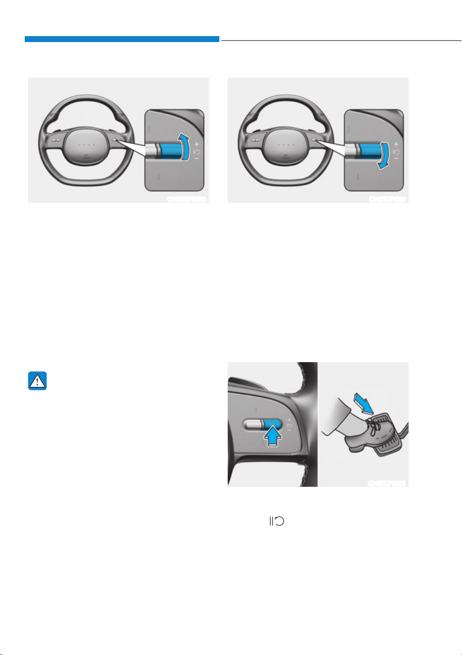
Driver Assistance System
7-72
ONE1071020
Increasing set speed
ś Push the + switch up and release
it immediately. The set speed will
increase by 1 mph (1 km/h) each time
the switch is operated in this manner.
ś Push the + switch up and hold it while
monitoring the set speed on the
cluster. The set speed will increase
by 10 km/h or 5 mph each time the
switch is operated in this manner.
Release the switch when the desired
speed is shown, and the vehicle will
accelerate to that speed. You can set
the speed to 110 mph (180 km/h).
WARNING
Check the driving condition before
using the + switch. Driving speed may
sharply increase when you push up and
hold the + switch.
ONE1071021
Decreasing set speed
ś Push the - switch down and release
it immediately. The set speed will
decrease by 1 mph (1 km/h) each time
the switch is operated in this manner.
ś Push the - switch down and hold it
while monitoring the set speed on the
cluster. The set speed will decrease
by 10 km/h or 5 mph each time the
switch is operated in this manner.
Release the switch at the speed you
want to maintain. You can set the
speed to 20 mph (30 km/h).
ONE1071022
Temporarily canceling Smart Cruise
Control
Press the switch or depress the brake
pedal to temporarily cancel Smart Cruise
Control.
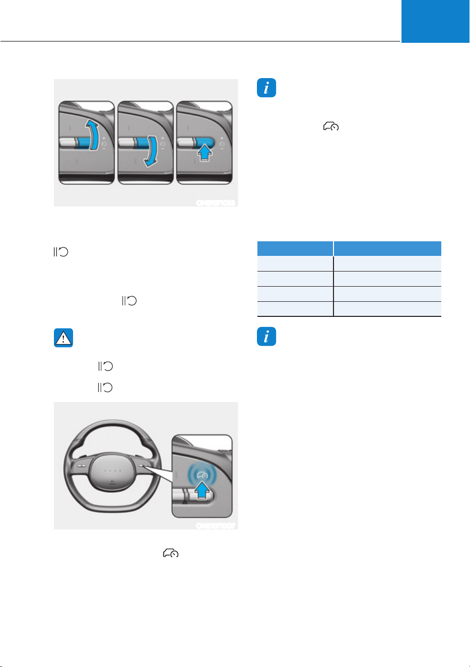
07
7-73
ONE1071023
Resuming Smart Cruise Control
To resume Smart Cruise Control after the
function was canceled, push the +, - or
switch.
If you push the + switch up or - switch
down, vehicle speed will be set to the
current speed on the cluster.
If you push the
switch, vehicle speed
will resume to the preset speed.
WARNING
Check the driving condition before
using the
switch. Driving speed may
sharply increase or decrease when you
press the
switch.
ONE1071007
Turning off Smart Cruise Control
Press the Driving Assist ( ) button to
turn Smart Cruise Control off.
Information
If your vehicle is equipped with Manual
Speed Limit Assist, press and hold the
Driving Assist (
) button to turn off
Smart Cruise Control. However Manual
Speed Limit Assist will turn on.
Based on Drive Mode
Smart Cruise Control will change
acceleration based on the drive mode
selected from Drive Mode Integrated
Control system. Refer to the following
chart.
Drive mode Smart Cruise Control
SNOW Normal
ECO Slow
SPORT Fast
NORMAL Normal
Information
ś For more details on drive mode, refer
to “Drive Mode Integrated Control
System” section in chapter 6.
ś Smart Cruise Control may not turn
on or off in some of the drive modes
for the operating conditions are not
satisfied.
ś If your vehicle is not equipped with
Drive Mode Integrated Control system,
Smart Cruise Control accelerates your
vehicle at a normal level.
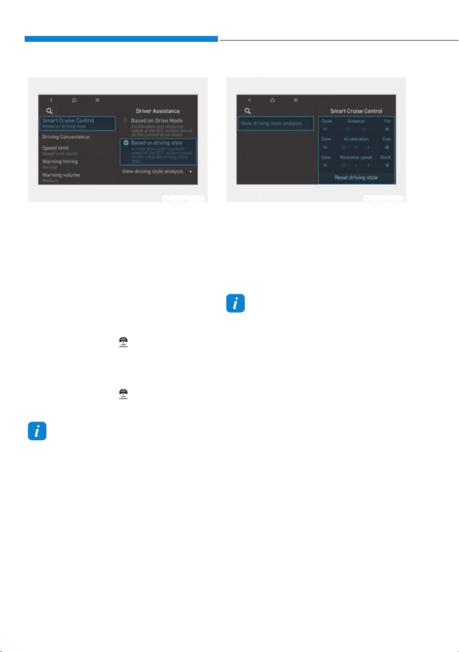
Driver Assistance System
7-74
ONE1071092N
Based on Driving Style (if equipped)
ś With the vehicle on, if ‘Driver
$VVLVWDQFHƟ6PDUW&UXLVH&RQWUROƟ
Based on Driving Style’ is selected
from the Settings menu, Smart Cruise
Control will operate based on the
driver’s driving style, such as vehicle
distance, acceleration, reaction
speed.
ś While Smart Cruise Control is
operating with ‘Based on Drive Mode’
selected, if you press and hold the
Vehicle Distance (
) button, Smart
Cruise Control will change to ‘Based
on Driving Style’. While Smart Cruise
Control is operating with ‘Based on
Driving Style’, you press and hold the
Vehicle Distance (
) button, it will
change to ‘Based on Drive Mode’.
Information
ś If equipped with Based on Driving
Style, ‘Based on Drive mode’ and
‘Based on Driving Style’ can be selected
from the settings menu by selecting
µ'ULYHU$VVLVWDQFHĺ6PDUW&UXLVH
Control’.
ś If ‘Based on Drive mode’ is selected,
Smart Cruise Control will operate
based on the drive mode selected.
ONE1071211N
Driving Style Settings (if equipped)
With the vehicle on, select ‘Driver
$VVLVWDQFHƟ6PDUW&UXLVH&RQWUROƟ
‘Driving Style Settings (or View driving
style analysis)’ from the Settings menu
to check the driver’s driving style, and to
change each driving style manually.
Information
ś ‘Driving Style Settings’ (or ‘View
driving style analysis’) is displayed
when ‘Based on Driving Style’ is
selected.
ś Smart Cruise Control learns the
driver’s driving styles only when the
driver drives the vehicle.

07
7-75
ONE1071202N
Warning Volume
With the vehicle on, select ‘Driver
$VVLVWDQFHƟ:DUQLQJ9ROXPHŔIURPWKH
Settings menu to change the Warning
Volume to ‘High’, ‘Medium’ or ‘Low’ for
Smart Cruise Control.
If you change the warning volume,
the Warning Volume of other Driver
Assistance systems may change.
Information
If the vehicle is restarted, Warning Volume
will maintain the last setting.
Smart Cruise Control Operation
Operating conditions
Smart Cruise Control operates when the
following conditions are satisfied.
Basic function
ś The gear is in D (Drive)
ś The driver’s door is closed
ś EPB (Electronic Parking Brake) is not
applied
ś Your vehicle speed is within the
operating speed range
-5
- 110mph (10 - 180km/h): when
there is no vehicle in front
-0
- 110mph (0 - 180km/h): when
there is a vehicle in front
ś ESC (Electronic Stability Control) or
ABS is on
ś ESC (Electronic Stability Control) or
ABS is not controlling the vehicle
ś Forward Collision-Avoidance Assist
brake control is not operating
ś Remote Smart Parking Assist brake
control is not operating (if equipped)
Information
When stopped behind another vehicle, the
driver can turn on Smart Cruise Control
while the brake pedal is depressed.
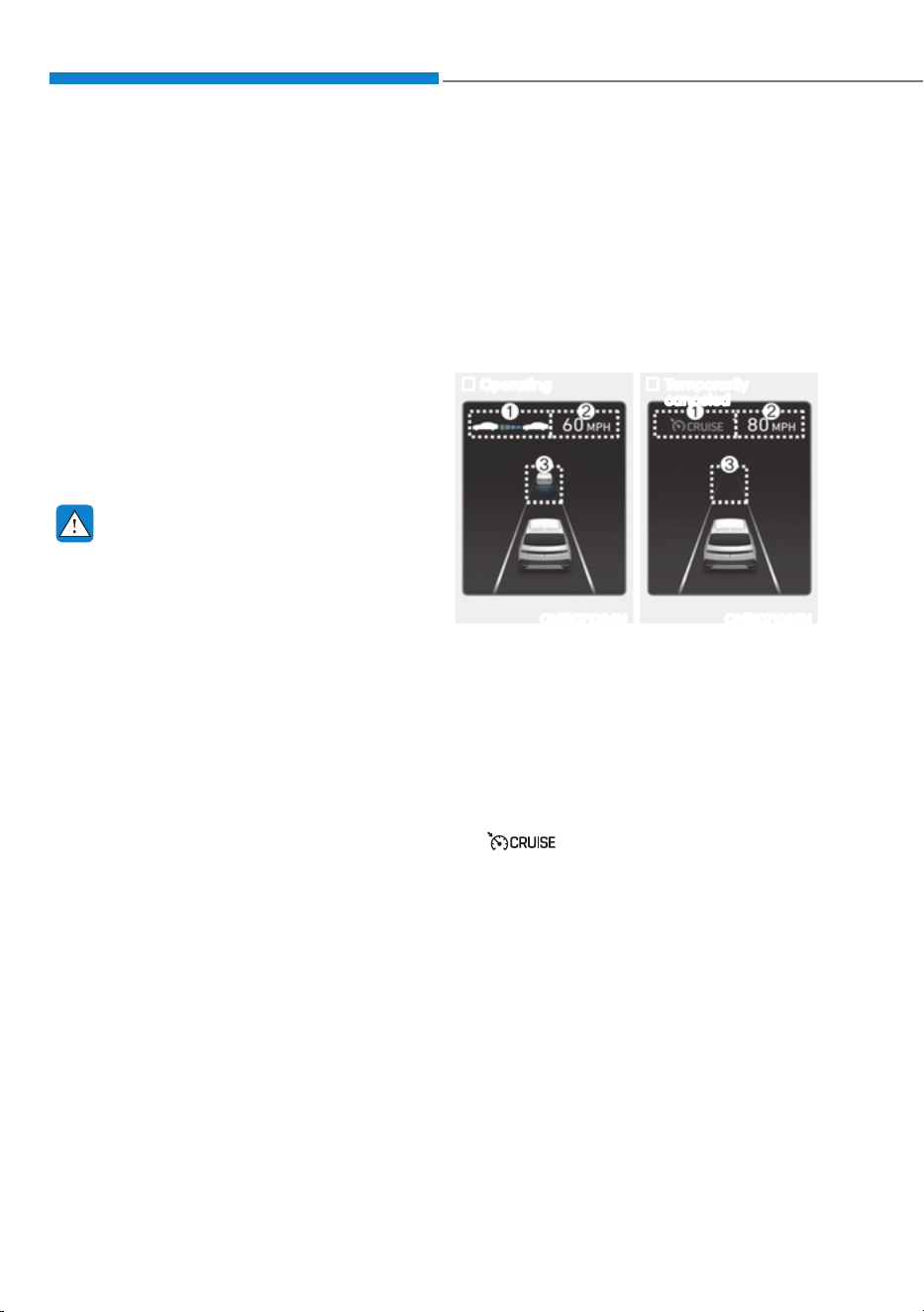
Driver Assistance System
7-76
Overtaking Acceleration Assist
Overtaking Acceleration Assist operates
when the turn signal indicator is turned
on to the left while Smart Cruise Control
is operating, and the following conditions
are satisfied:
ś Your vehicle speed is above 40 mph
(60 km/h)
ś The hazard warning flasher is off
ś A vehicle is detected in front of your
vehicle
ś Deceleration is not needed to
maintain distance with the vehicle in
front
WARNING
ś When the turn signal indicator is
turned on to the left (left-hand drive)
or turned on to the right (right-
hand drive) while there is a vehicle
ahead, the vehicle may accelerate
temporarily. Pay attention to the
road conditions at all times.
ś Regardless of your countries driving
direction, Overtaking Acceleration
Assist will operate when the
conditions are satisfied. When
using the function in countries with
different driving direction, always
check the road conditions at all
times.
Display and control
Basic function
You can see the status of the Smart
Cruise Control operation in the Driving
Assist view on the cluster. Refer to “View
Modes” section in chapter 4.
Smart Cruise Control will be displayed
as below depending on the status of the
function.
Operating Temporarily
canceled
ONE1071094N ONE1071095N
ś When operating
(1) Whether there is a vehicle ahead and
the selected distance level
(2) Set speed
(3) Whether there is a vehicle ahead and
the target vehicle distance
ś When temporarily canceled
(1)
indicator
(2) The previous set speed is shaded.
(3) Vehicle ahead and distance level not
displayed
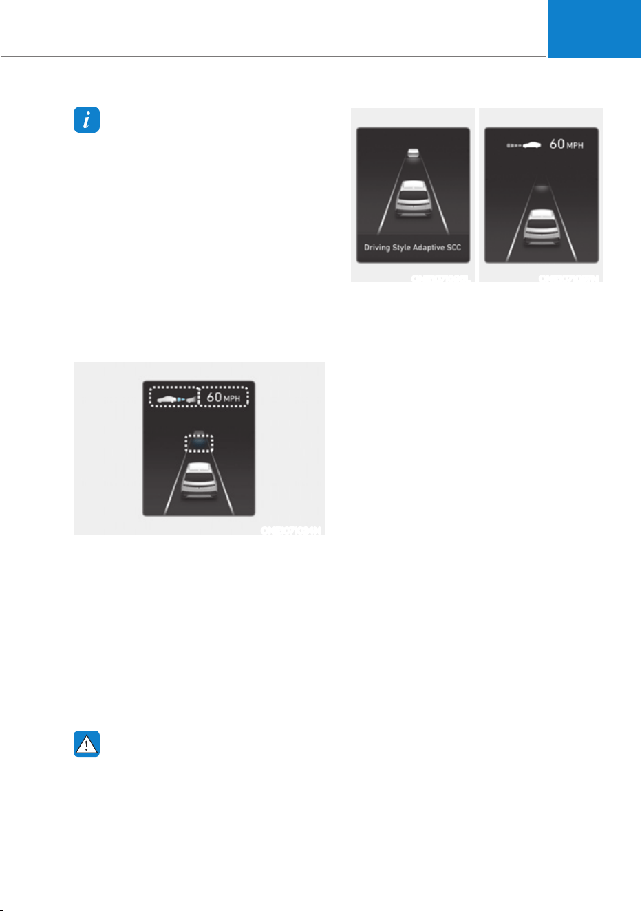
07
7-77
Information
ś The distance of the front vehicle on the
cluster is displayed according to the
actual distance between your vehicle
and the vehicle ahead.
ś The target distance may vary according
to the vehicle speed and the set
distance level. If vehicle speed is low,
even though the vehicle distance have
changed, the change of the target
vehicle distance may be small.
ś The images and colors in the
instrument cluster may differ
depending on the cluster type or theme
selected from the instrument cluster.
ONE1071024N
Accelerating temporarily
If you want to speed up temporarily
without altering the set speed while
Smart Cruise Control is operating,
depress the accelerator pedal. While the
accelerator pedal is depressed, the set
speed, distance level and target distance
will blink on the cluster.
However, if the accelerator pedal is
depressed insufficiently, the vehicle may
decelerate.
WARNING
Be careful when accelerating
temporarily, because the speed and
distance is not controlled automatically
even if there is a vehicle in front of you.
ONE1071096L ONE1071097N
Based on Driving Style operating
When Based on Driving Style is
operating, ‘Driving Style Adaptive SCC’
message will appear on the cluster for
2 seconds, and the distance level and
target distance will be displayed based
on the driving style.
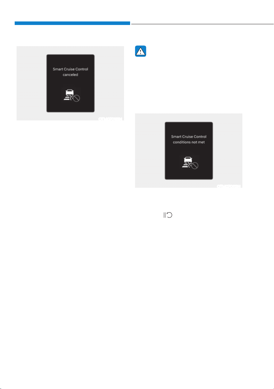
Driver Assistance System
7-78
OTM070113N
Smart Cruise Control temporarily
canceled
Smart Cruise Control will be temporarily
canceled automatically when:
ś The vehicle speed is above 120mph
(190km/h)
ś The vehicle is stopped for a certain
period of time
ś The accelerator pedal is continuously
depressed for a certain period of time
ś The conditions for the Smart Cruise
Control to operate is not satisfied
If Smart Cruise Control is temporarily
canceled automatically, the ‘Smart
Cruise Control canceled’ warning
message will appear on the cluster, and
an audible warning will sound to warn
the driver.
If Smart Cruise Control is temporarily
canceled while the vehicle is at a
standstill with the function activated,
EPB (Electronic Parking Brake) maybe
applied.
WARNING
When Smart Cruise Control is
temporarily canceled, distance with the
front vehicle will not be maintained.
Always have your eyes on the road
while driving, and if necessary, depress
the brake pedal to reduce your driving
speed in order to maintain a safe
distance.
OTM070112N
Smart Cruise Control conditions not
satisfied
If the Driving Assist button, + switch,
- switch or
switch is pushed
when Smart Cruise Control operating
conditions are not satisfied, the ‘Smart
Cruise Control conditions not met’ will
appear on the cluster, and an audible
warning will sound.
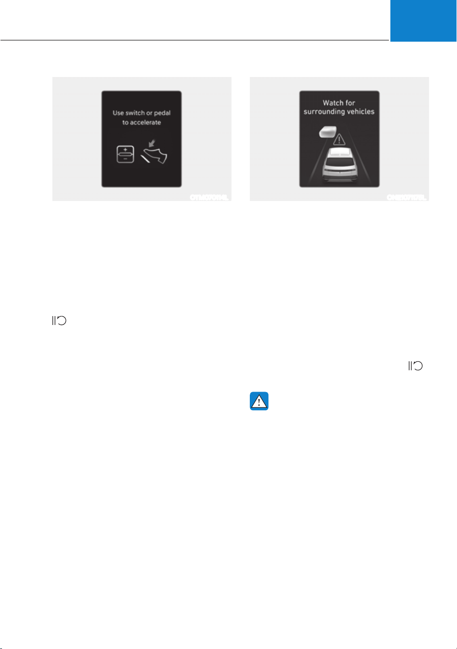
07
7-79
OTM070114L
In traffic situation
In traffic, your vehicle will stop if the
vehicle ahead of you stops. Also, if the
vehicle ahead of you starts moving, your
vehicle will start as well. In addition, after
the vehicle has stopped and a certain
time have passed, the ‘Use switch or
pedal to accelerate’ message will appear
on the cluster. Depress the accelerator
pedal or push the + switch, - switch or
switch to start driving.
ONE1071175L
Warning road conditions ahead
In the following situation, the ‘Watch for
surrounding vehicles’ warning message
will appear on the cluster, and an audible
warning will sound to warn the driver of
road conditions ahead.
- The vehicle in front disappears when
Smart Cruise Control is maintaining
the distance with the vehicle ahead
while driving below a certain speed.
- While the ‘Use switch or pedal to
accelerate’ message is displayed on
the cluster, if there is no vehicle in
front or the vehicle is far away from
you, and the + switch, – switch or
switch is pushed.
WARNING
Always pay attention to vehicles or
objects that may suddenly appear in
front of you, and if necessary, depress
the brake pedal to reduce your driving
speed in order to maintain a safe
distance.
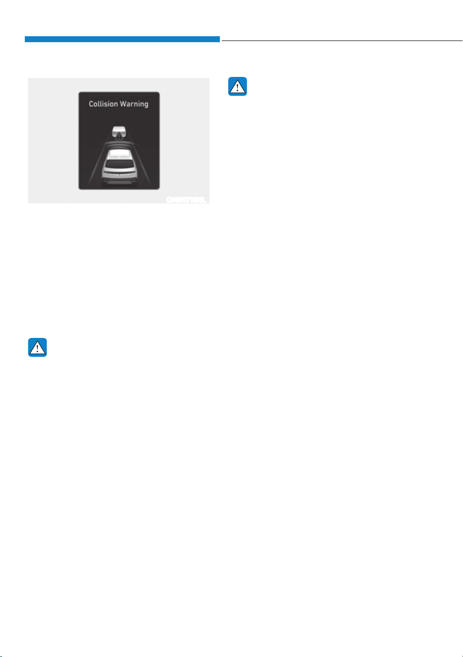
Driver Assistance System
7-80
ONE1071183L
Collision Warning
While Smart Cruise Control is operating,
when the collision risk with the vehicle
ahead is high, the ‘Collision Warning’
warning message will appear on the
cluster, and an audible warning will
sound to warn the driver. Always have
your eyes on the road while driving, and
if necessary, depress the brake pedal to
reduce your driving speed in order to
maintain a safe distance.
WARNING
In the following situations, Smart Cruise
Control may not warn the driver of a
collision.
- The distance from the front vehicle
is near, or the vehicle speed of the
front vehicle is faster or similar with
your vehicle
- The speed of the front vehicle is very
slow or is at a standstill
- The accelerator pedal is depressed
right after Smart Cruise Control is
turned on
WARNING
Take the following precautions when
using Smart Cruise Control:
ś Smart Cruise Control does not
substitute for proper and safe
driving. It is the responsibility of the
driver to always check the speed and
distance to the vehicle ahead.
ś Smart Cruise Control may not
recognize unexpected and sudden
situations or complex driving
situations, so always pay attention to
driving conditions and control your
vehicle speed.
ś Keep Smart Cruise Control off when
the function is not in use to avoid
inadvertently setting a speed.
ś Do not open the door or leave the
vehicle when Smart Cruise Control
is operating, even if the vehicle is
stopped.
ś Always be aware of the selected
speed and headway distance.
ś Keep a safe distance according to
road conditions and vehicle speed.
If the headway distance is too close
during high-speed driving, a serious
collision may result.

07
7-81
ś When maintaining distance with
the vehicle ahead, if the front
vehicle disappears, Smart Cruise
Control may suddenly accelerate to
the set speed. Always be aware of
unexpected and sudden situations
from occurring.
ś Vehicle speed may decrease on an
upward slope and increase on a
downward slope.
ś Always be aware of situations such
as when a vehicle cuts in suddenly.
ś When you are turn off Smart Cruise
Control for safety reasons.
ś Turn off Smart Cruise Control when
your vehicle is being towed.
ś Smart Cruise Control may not
operate properly if interfered by
strong electromagnetic waves.
ś Smart Cruise Control may not
detect an obstacle in front and lead
to a collision. Always look ahead
cautiously to prevent unexpected
and sudden situations from
occurring.
ś Vehicles moving in front of you with
a frequent lane change may cause
a delay in Smart Cruise Control
reaction or may cause Smart Cruise
Control to react to a vehicle actually
in an adjacent lane. Always drive
cautiously to prevent unexpected
and sudden situations from
occurring.
ś Always be aware of the surroundings
and drive safely, even though a
warning message does not appear or
an audible warning does not sound.
ś If any other system’s warning
message is displayed or warning
sound is generated, Smart Cruise
Control warning message may not
be displayed and warning sound may
not be generated.
ś You may not hear the warning sound
of Forward Collision-Avoidance
Assist if the surrounding is noisy.
ś The vehicle manufacturer is not
responsible for any traffic violation
or accidents caused by the driver.
ś Always set the vehicle speed under
the speed limit in your country.
ś Vehicle distance, acceleration and
reaction speed may change if the
driver’s driving style changes.
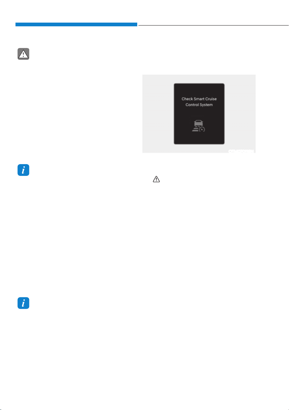
Driver Assistance System
7-82
CAUTION
ś The vehicle must be driven
sufficiently to reflect the actual
driving style of the driver, such as
inter-vehicle distance, acceleration
and reaction speed.
ś Based on Driving style does not
reflect whether the driver has
changed when determining the
driver's driving style.
ś If you are driving in special
conditions, such as snow, rain, fog
or steep slopes, the vehicle may not
be driven according to the driver’s
driving style.
Information
ś Smart Cruise Control may not operate
for 15 seconds after the vehicle is
started or the front view camera or
front radar is initialized.
ś You may hear a sound when the brake
is controlled by Smart Cruise Control.
ś Based on Driving Style may not reflect
the driver’s driving style or driving
conditions that affects driving safety.
ś Based on Driving Style does not reflect
any other driving style other than
inter-vehicle distance, acceleration and
reaction speed.
ś The paddle shifter does not operate
when Smart Cruise Control system is
activated.
Information
The images or colors may be displayed
differently depending on the specifications
of the instrument panel or theme.
Smart Cruise Control
Malfunction and Limitations
Smart Cruise Control malfunction
OTM070116N
When Smart Cruise Control is not working
properly, the ‘Check Smart Cruise Control
system’ warning message will appear, and
the
warning light will illuminate on the
cluster. Have the vehicle be inspected by
an authorized HYUNDAI dealer.

07
7-83
Smart Cruise Control disabled
OTM070115N
When the front radar cover or sensor
is covered with snow, rain, or foreign
material, it can reduce the detecting
performance and temporarily limit or
disable Smart Cruise Control.
If this occurs the ‘Smart Cruise Control
disabled. Radar blocked’warning message
will appear for a certain period of time on
the cluster.
Smart Cruise Control will operate properly
when snow, rain or foreign material is
removed.
WARNING
Even though the warning message does
not appear on the cluster, Smart Cruise
Control may not properly operate.
CAUTION
Smart Cruise Control may not properly
operate in an area (for example, open
terrain), where any objects are not
detected after turning ON the vehicle.
Limitations of Smart Cruise Control
Smart Cruise Control may not operate
properly, or it may operate unexpectedly
under the following circumstances:
ś The detecting sensor or the
surroundings are contaminated or
damaged
ś Washer fluid is continuously sprayed,
or the wiper is on
ś The camera lens is contaminated due
to tinted, filmed or coated windshield,
damaged glass, sticky foreign material
(sticker, bug, etc.) on the glass
ś Moisture is not removed or frozen on
the windshield
ś The field of view of the front view
camera is obstructed by sun glare
ś Street light or light from an oncoming
traffic is reflected on the wet road
surface, such as a puddle on the road
ś The temperature around the front
view camera is high or low due to
surrounding environment
ś An object is placed on the dashboard
ś The surrounding is very bright
ś The surrounding is very dark, such as
in a tunnel, etc.
ś The brightness changes suddenly, for
example when entering or exiting a
tunnel
ś The brightness outside is low, and the
headlamps are not on or are not bright
ś Driving in heavy rain or snow, or thick
fog
ś Driving through steam, smoke or
shadow

Driver Assistance System
7-84
ś Only part of the vehicle is detected
ś The vehicle in front has no tail lights,
tail lights are located unusually, etc.
ś The brightness outside is low, and the
tail lamps are not on or are not bright
ś The rear of the front vehicle is small
or does not look normal (for example,
tilted, overturned, etc.)
ś The front vehicle’s ground clearance is
low or high
ś A vehicle suddenly cuts in front
ś Your vehicle is being towed
ś Driving through a tunnel or iron bridge
ś Driving near areas containing metal
substances, such as a construction
zone, railroad, etc.
ś An object reflecting off the front radar
such as a guardrail, nearby vehicle,
etc.
ś The bumper around the front radar is
impacted, damaged or the front radar
is out of position
ś The temperature around the front
radar is high or low
ś Driving in vast areas where there
are few vehicles or structures (for
example, desert, meadow, suburb,
etc.)
ś The vehicle in front is made of
material that does not reflect on the
front radar
ś Driving near a highway interchange or
tollgate
ś Driving on a slippery surface due to
snow, water puddle, ice, etc.
ś Driving on a curved road
ś The vehicle in front is detected late
ś The vehicle in front is suddenly
blocked by an obstacle
ś The vehicle in front suddenly changes
lane or suddenly reduces speed
ś The vehicle in front is bent out of
shape
ś The front vehicle’s speed is fast or
slow
ś With a vehicle in front, your vehicle
changes lane at low speed
ś The vehicle in front is covered with
snow
ś Unstable driving
ś You are on a roundabout and the
vehicle in front is not detected
ś You are continuously driving in a circle
ś Driving in a parking lot
ś Driving through a construction area,
unpaved road, partial paved road,
uneven road, speed bumps, etc.
ś Driving on an incline road, curved
road, etc.
ś Driving through a roadside with trees
or streetlights
ś The adverse road conditions cause
excessive vehicle vibrations while
driving
ś Your vehicle height is low or high
due to heavy loads, abnormal tire
pressure, etc.
ś Driving through a narrow road where
trees or grass are overgrown
ś There is interference by
electromagnetic waves, such as
driving in an area with strong radio
waves or electrical noise
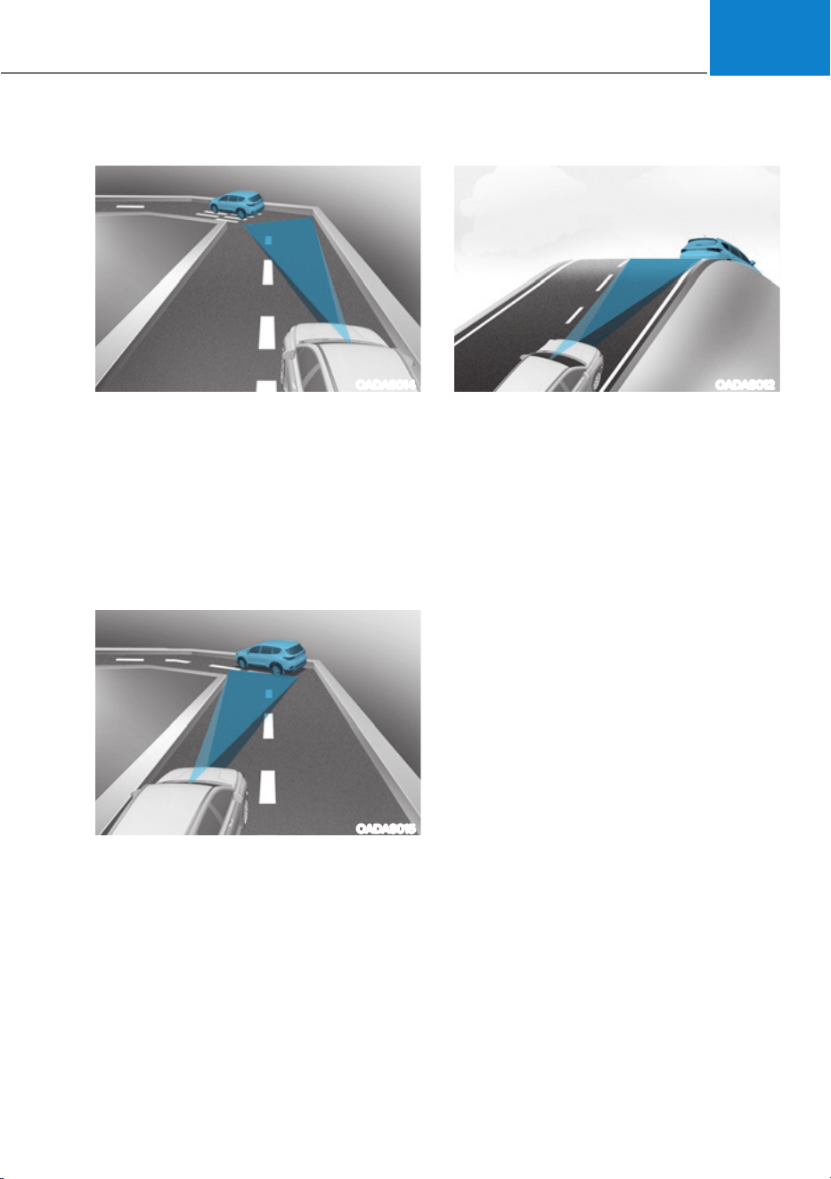
07
7-85
ś Driving on a curved road
OADAS014
On curves, Smart Cruise Control may
not detect a vehicle in the same lane,
and may accelerate to the set speed.
Also, vehicle speed may rapidly
decrease when the vehicle ahead is
detected suddenly.
Select the appropriate set speed on
curves and apply the brake pedal or
accelerator pedal according to the
road and driving conditions ahead.
OADAS015
Your vehicle speed can be reduced
due to a vehicle in the adjacent lane.
Apply the accelerator pedal and select
the appropriate set speed. Check
to be sure that the road conditions
permit safe operation of the Smart
Cruise Control.
ś Driving on an inclined road
OADAS012
During uphill or downhill driving, the
Smart Cruise Control may not detect
a moving vehicle in your lane, and
cause your vehicle to accelerate to
the set speed. Also, vehicle speed will
rapidly decrease when the vehicle
ahead is detected suddenly.
Select the appropriate set speed on
inclines and apply the brake pedal or
accelerator pedal according to the
road and driving conditions ahead.
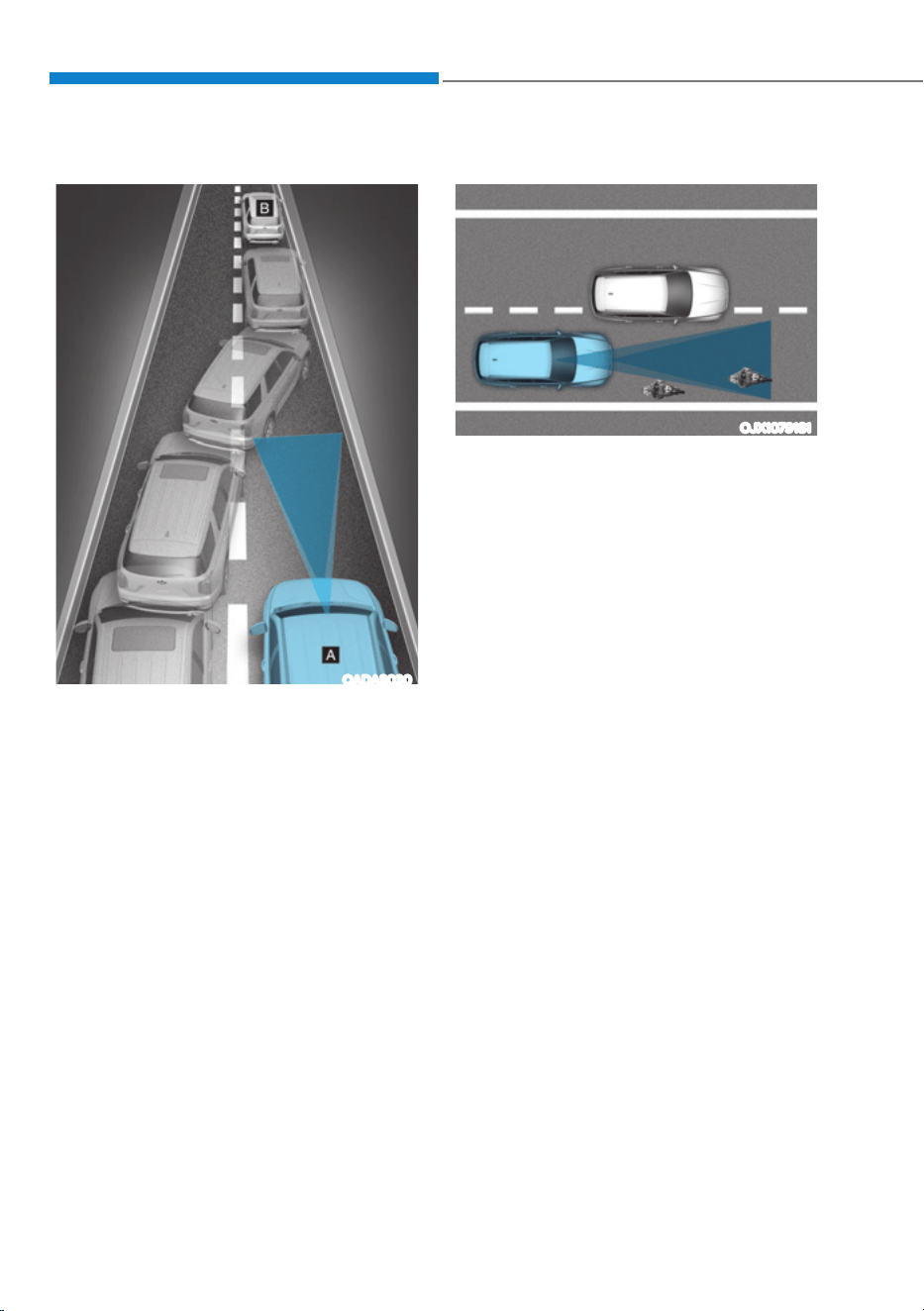
Driver Assistance System
7-86
ś Changing lanes
OADAS030
[A] : Your vehicle, [B] : Lane changing vehicle
When a vehicle moves into your lane
from an adjacent lane, it cannot be
detected by the sensor until it is in the
sensor's detection range. Smart Cruise
Control may not immediately detect
the vehicle when the vehicle changes
lanes abruptly. In this case, you must
maintain a safe braking distance, and
if necessary, depress the brake pedal
to reduce your driving speed in order
to maintain a safe distance.
ś Detecting vehicle
OJX1079181
In the following cases, some vehicles
in your lane cannot be detected by the
sensor:
- Vehicles offset to one side
- Slow-moving vehicles or sudden-
decelerating vehicles
- Oncoming vehicles
- Stopped vehicles
- Vehicles with small rear profile, such
as trailers
- Narrow vehicles, such as
motorcycles or bicycles
- Special vehicles
- Animals and pedestrians
Adjust your vehicle speed by
depressing the brake pedal according
to the road and driving conditions
ahead.
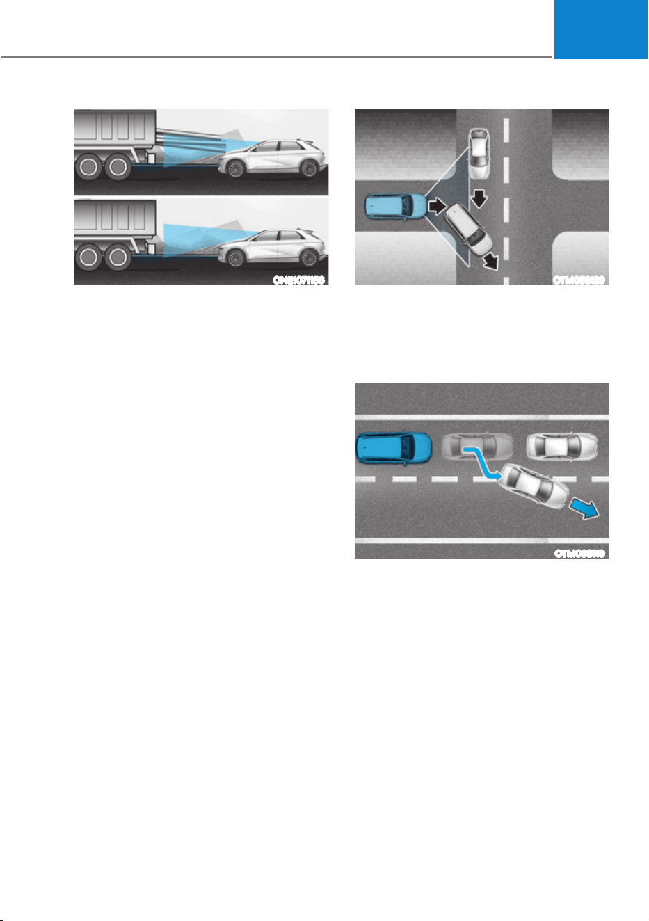
07
7-87
ONE1071156
In the following cases, the vehicle
in front cannot be detected by the
sensor:
- Vehicles with higher ground
clearance or vehicles carrying loads
that stick out of the back of the
vehicle
- Vehicles that has the front lifted due
to heavy loads
- You are steering your vehicle
- Driving on narrow or sharply curved
roads
Adjust your vehicle speed by
depressing the brake pedal according
to the road and driving conditions
ahead.
OTM058129
ś When a vehicle ahead disappears
at an intersection, your vehicle may
accelerate.
Always pay attention to road and
driving conditions while driving.
OTM058119
ś When a vehicle in front of you merges
out of the lane, Smart Cruise Control
may not immediately detect the new
vehicle that is now in front of you.
Always pay attention to road and
driving conditions while driving.
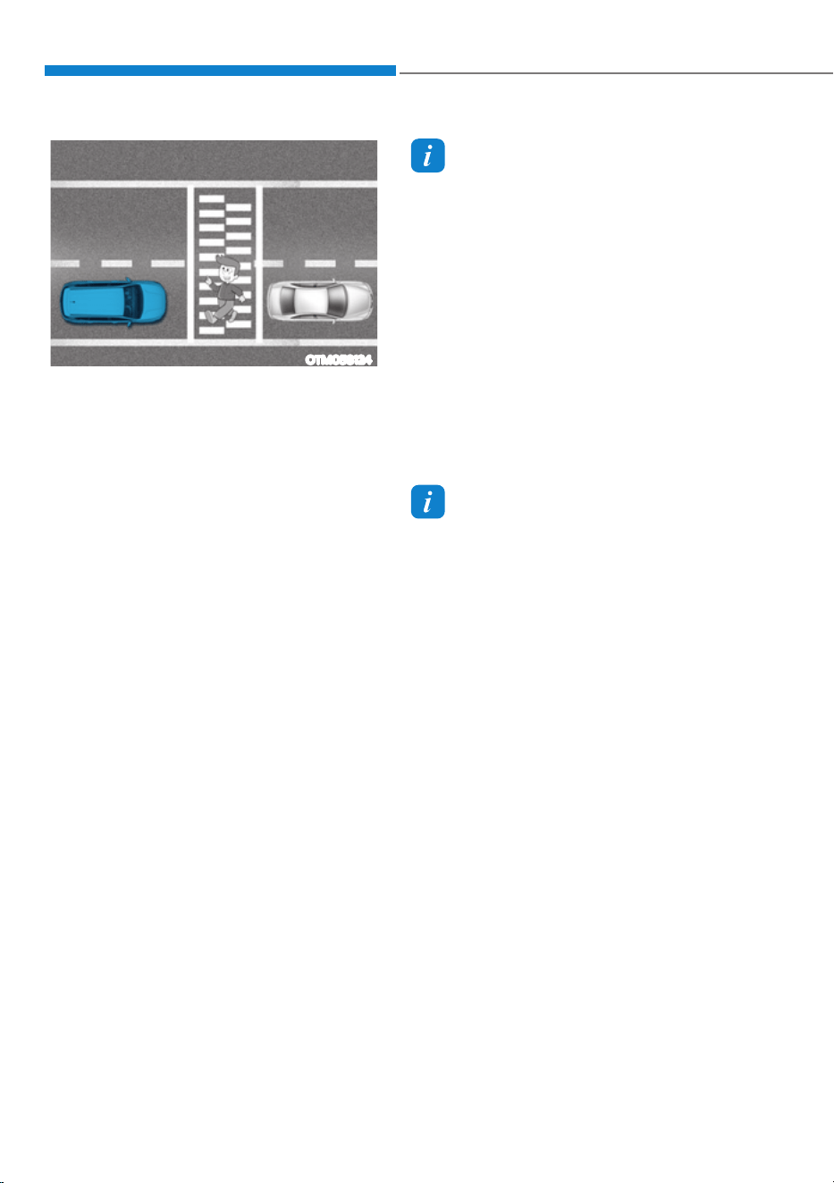
Driver Assistance System
7-88
OTM058124
ś Always look out for pedestrians when
your vehicle is maintaining a distance
with the vehicle ahead.
Information
This device complies with Part 15 of the
FCC rules.
Operation is subject to the following three
conditions:
1. This device may not cause harmful
interference, and
2. This device must accept any
interference received, including
interference that may cause undesired
operation of the device.
3. Changes or modifications not expressly
approved by the party responsible
for compliance could void the user's
authority to operate the device.
Information
Radio frequency radiation exposure
information:
This equipment complies with FCC
radiation exposure limits set forth for an
uncontrolled environment.
This equipment should be installed and
operated with minimum distance of 8 in.
(20 cm) between the radiator (antenna)
and your body.
This transmitter must not be co-located or
operating in conjunction with any other
antenna or transmitter.
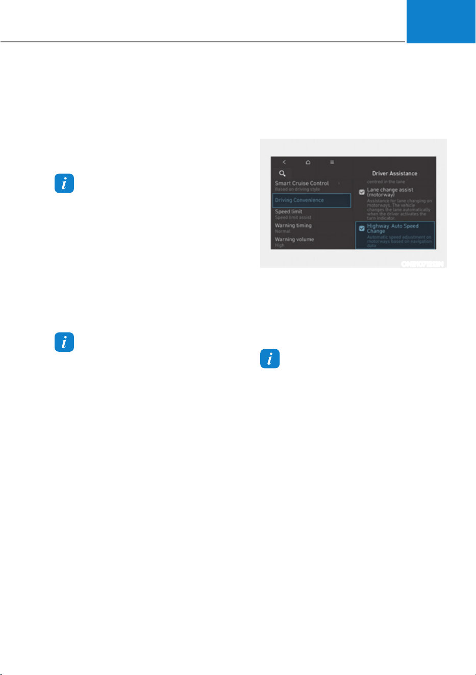
07
7-89
Navigation-based Smart Cruise Control
can helps drive at a certain speed
according to the road conditions when
driving on highways by using road
information from the navigation system
while Smart Cruise Control is operating.
Information
ś Navigation-based Smart Cruise Control
is available only on controlled access
road of certain highways.
à Controlled access road indicates
roads with limited entrances and
exits that allow uninterrupted high
speed traffic flow. Only passenger
cars and motorcycles are allowed on
controlled access roads.
ś Additional highways may be expanded
by future navigation updates.
Information
Navigation-based Smart Cruise Control
operates on main roads of highways,
and does not operate on interchanges or
junctions.
Highway Curve Zone Auto Slowdown
If vehicle speed is high, Highway Curve
Zone Auto Slowdown function will
temporarily decelerate your vehicle
or limit acceleration to help you drive
safely on a curve based on the curve
information from the navigation.
Highway Set Speed Auto Change
Highway Set Speed Auto Change
function automatically changes Smart
Cruise Control set speed based on
the speed limit information from the
navigation.
Navigation-based Smart Cruise
Control Settings
Setting features
ONE1071212N
With the vehicle on, select ‘Driver
$VVLVWDQFHƟ'ULYLQJ$VVLVWƟ+LJKZD\
Auto Speed Change’ from the Settings
menu to turn on Navigation-based Smart
Cruise Control and deselect to turn off
the function.
Information
When there is a problem with Navigation-
based Smart Cruise Control, the function
cannot be set from the Settings menu.
1$9,*$7,21ǘ%$6('60$57&58,6(&21752/ǣ16&&Ǥ
ǣ,)(48,33('Ǥ
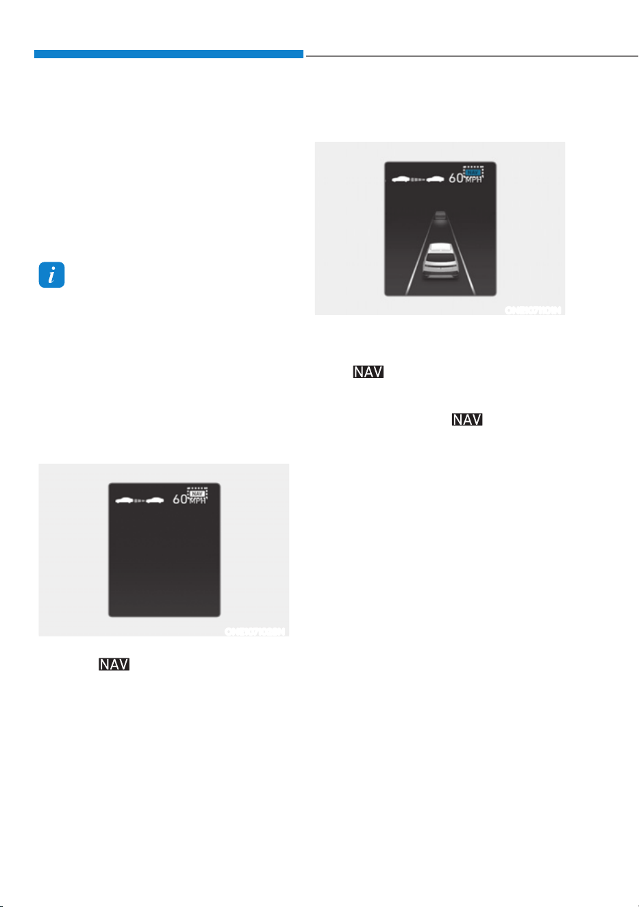
Driver Assistance System
7-90
Navigation-based Smart Cruise
Control Operation
Operating conditions
Navigation-based Smart Cruise Control
is ready to operate if all of the following
conditions are satisfied:
ś Smart Cruise Control is operating
ś Driving on main roads of highways
Information
For more details on how to operate Smart
Cruise Control, refer to “Smart Cruise
Control (SCC)” section in this chapter.
Display and control
When Navigation-based Smart Cruise
Control operates, it will be displayed on
the cluster as follows:
Navigation-based Smart Cruise Control
standby
ONE1071028N
If the operating conditions are satisfied,
the white
symbol will illuminate.
Navigation-based Smart Cruise Control
operating
ONE1071101N
If temporary deceleration is required in
the standby state and Navigation-based
Smart Cruise Control is operating, the
green
symbol will illuminate on the
cluster.
If the Highway Set Speed Auto Change
function operates, the
symbol and
set speed will illuminate in green on
the cluster, and an audible warning will
sound.
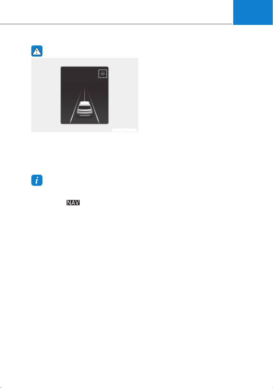
07
7-91
WARNING
ONE1071102N
‘Drive carefully’ warning message will
appear in the following circumstances:
- Navigation-based Smart Cruise
Control is not able to slow down your
vehicle to a safe speed
Information
Highway Curve Zone Auto Slowdown and
Highway Set Speed Auto Change function
uses the same
symbol.
Highway Curve Zone Auto Slowdown
ś Depending on the curve ahead on the
highway, the vehicle will decelerate,
and after passing the curve, the
vehicle will accelerate to Smart Cruise
Control set speed.
ś Vehicle deceleration time may differ
depending on the vehicle speed
and the degree of the curve on the
road. The higher the driving speed,
deceleration will start faster.
Highway Set Speed Auto Change
ś Highway Set Speed Auto Change
function will operate when Smart
Cruise Control set speed and the
highway speed limit is matched.
ś While Highway Set Speed Auto
Change function is operating, when
the highway, speed limit changes,
Smart Cruise Control set speed
automatically changes to the changed
speed limit.
ś If Smart Cruise Control set speed is
adjusted different from the speed
limit, Highway Set Speed Auto Change
function will be in the standby state.
ś If Highway Set Speed Auto Change
function has changed to the standby
state by driving on a road other than
the highway main road, Highway Set
Speed Auto Change function will
operate again when you drive on the
main road again without setting the
set speed.

Driver Assistance System
7-92
ś If Highway Set Speed Auto Change
function has changed to the standby
state by depressing the brake pedal
or pressing the
switch on the
steering wheel, press the
switch to
restart the function.
ś Highway Set Speed Auto Change
function does not operate on highway
interchanges or junctions.
Information
ś Highway Set Speed Auto Change
function only operates based on the
speed limits of the highway, it does not
work with the speed cameras.
ś When Highway Set Speed Auto Change
function is operating, the vehicle
automatically accelerates or decelerates
when the highway speed limit changes.
ś The maximum set speed for Highway
Set Speed Auto Change function is 90
mph (140 km/h).
ś If the speed limit of a new road is not
updated in the navigation, Highway Set
Speed Auto Change function may not
operate properly.
ś If the speed unit is set to a unit other
than the speed unit used in your
country, Highway Set Speed Auto
Change function may not operate
properly.
Information
The images or colors may be displayed
differently depending on the specifications
of the instrument panel or theme.
Limitations of Navigation-based
Smart Cruise Control
Navigation-based Smart Cruise Control
may not operate properly under the
following circumstances:
ś The navigation is not working properly
ś Map information is not transmitted
due to infotainment system's
abnormal operation
ś Speed limit and road information in
the navigation is not updated
ś The map information and the actual
road is different because of real-time
GPS data or map information error
ś The navigation searches for a route
while driving
ś GPS signals are blocked in areas such
as a tunnel
ś A road that divides into two or more
roads and joins again
ś

07
7-93
ś The driver goes off course the route
set in the navigation
ś The route to the destination is
changed or canceled by resetting the
navigation
ś The vehicle enters a service station or
rest area
ś Android Auto or Car Play is operating
ś The navigation cannot detect the
current vehicle position (for example,
elevated roads including overpass
adjacent to general roads or nearby
roads exist in a parallel way)
ś The navigation is being updated while
driving
ś The navigation is being restarted while
driving
ś The speed limit of some sections
changes according to the road
situations
ś Driving on a road under construction
ś Driving on a road that is controlled
ś There is bad weather, such as heavy
rain, heavy snow, etc.
ś Driving on a road that is sharply
curved
OJX1070280L
[1] : Set route, [2] : Branch line, [3] : Driving route,
[4] : Main road, [5] : Curved road section
ś When there is a difference between
the navigation set route (branch line)
and the driving route (main road),
Highway Curve Zone Auto Slowdown
function may not operate until the
driving route is recognized as the
main road.
ś When the vehicle's driving route
is recognized as the main road by
maintaining the main road instead
of the navigation set route, Highway
Curve Zone Auto Slowdown function
will operate. Depending on the
distance to the curve and the current
vehicle speed, vehicle deceleration
may not be sufficient or may
decelerate rapidly.
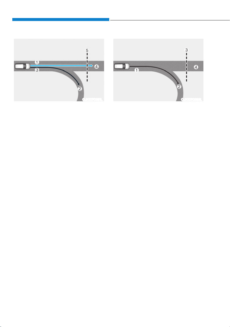
Driver Assistance System
7-94
OJX1070281L
[1] : Set route, [2] : Branch line, [3] : Driving route,
[4] : Main road, [5] : Curved road section
ś When there is a difference between
the navigation route (main road)
and the driving route (branch line),
Highway Curve Zone Auto Slowdown
function will operate temporarily
based on the curve information on the
main road.
ś When it is judged that you are driving
out of the route by entering the
highway interchange or junction,
Highway Curve Zone Auto Slowdown
function will not operate.
ś
OJX1070282L
[1] : Driving route, [2] : Branch line,
[3] : Curved road section, [4] : Main road
ś If there is no destination set on the
navigation, Highway Curve Zone Auto
Slowdown function will operate based
on the curve information on the main
road.
ś Even if you depart from the main road,
Highway Curve Zone Auto Slowdown
function may temporarily operate
due to navigation information of the
highway curve section.

07
7-95
WARNING
ś Navigation-based Smart Cruise
Control is not a substitute for safe
driving practices, but a convenience
function. Always have your eyes on
the road, and it is the responsibility
of the driver to avoid violating traffic
laws.
ś The navigation’s speed limit
information may differ from the
actual speed limit information on the
road. It is the driver's responsibility
to check the speed limit on the
actual driving road or lane.
ś Navigation-based Smart Cruise
Control will automatically be
canceled when you leave the
highway main road. Always pay
attention to road and driving
conditions while driving.
ś Navigation-based Smart Cruise
Control may not operate due to the
existence of leading vehicles and
the driving conditions of the vehicle.
Always pay attention to road and
driving conditions while driving.
ś When you are towing a trailer or
another vehicle, turn off Navigation-
based Smart Cruise Control for safety
reasons.
ś After you pass through a tollgate on
a highway, Navigation-based Smart
Cruise Control will operate based on
the first lane. If you enter one of the
other lanes, Navigation-based Smart
Cruise Control might not operate
properly.
ś The vehicle will accelerate if the
driver depresses the accelerator
pedal while Navigation-based Smart
Cruise Control is operating, and
the function will not decelerate the
vehicle. However, if the accelerator
pedal is depressed insufficiently, the
vehicle may decelerate.
ś If the driver accelerates and
releases the accelerator pedal while
Navigation-based Smart Cruise
Control is operating, the vehicle may
not decelerate sufficiently or may
rapidly decelerate to a safe speed.
ś If the curve is too large or too small,
Navigation-based Smart Cruise
Control may not operate.

Driver Assistance System
7-96
Information
ś A time gap could occur between the
navigation’s guidance and when
Navigation-based Smart Cruise Control
operation starts and ends.
ś The speed information on the cluster
and navigation may differ.
ś Even if you are driving at a speed lower
than Smart Cruise Control set speed,
acceleration may be limited by the
curve sections ahead.
ś If Navigation-based Smart Cruise
Control is operating while leaving the
main road to enter an interchange,
junction, rest area, etc., the function
may operate for a certain period of
time.
ś Deceleration by Navigation-based
Smart Cruise Control may feel it is not
sufficient due to road conditions such
as uneven road surfaces, narrow lanes,
etc.
Information
This device complies with Part 15 of the
FCC rules.
Operation is subject to the following three
conditions:
1. This device may not cause harmful
interference, and
2. This device must accept any
interference received, including
interference that may cause undesired
operation of the device.
3. Changes or modifications not expressly
approved by the party responsible
for compliance could void the user's
authority to operate the device.
Information
Radio frequency radiation exposure
information:
This equipment complies with FCC
radiation exposure limits set forth for an
uncontrolled environment.
This equipment should be installed and
operated with minimum distance of 8 in.
(20 cm) between the radiator (antenna)
and your body.
This transmitter must not be co-located or
operating in conjunction with any other
antenna or transmitter.
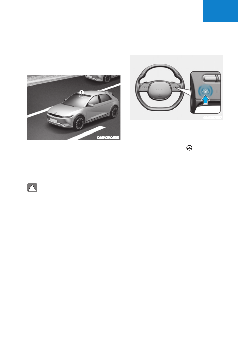
07
7-97
Lane Following Assist is designed to help
detect lane markings and/or vehicles on
the road, and assists the driver’s steering
to help center the vehicle in the lane.
Detecting sensor
ONE1071002K
[1]: Front view camera
The front view camera is used as a
detecting sensor to detect lane markings
and front vehicles.
Refer to the picture above for the
detailed location of the detecting sensor.
CAUTION
For more details on the precautions
of the front view camera, refer to
“Forward Collision-Avoidance Assist
(FCA)” section in this chapter.
Lane Following Assist Settings
Setting features
ONE1071157
Turning Lane Following Assist On/Off
With the vehicle on, shortly press the
Lane Driving Assist button located on the
steering wheel to turn on Lane Following
Assist. The grey or green
indicator
light will illuminate on the cluster.
Press the button again to turn off the
function.
/$1()2//2:,1*$66,67ǣ/)$Ǥ
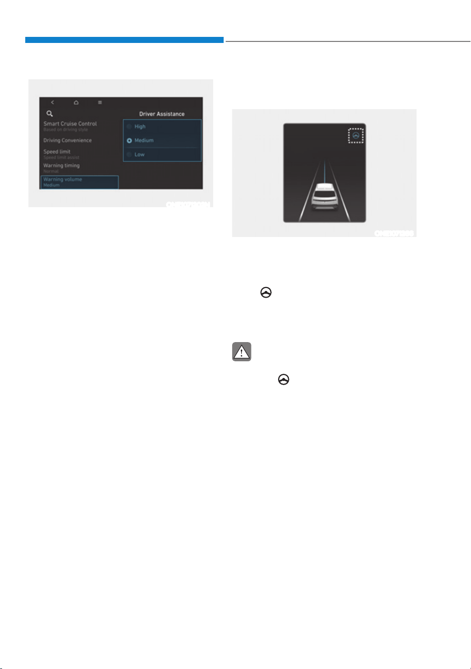
Driver Assistance System
7-98
ONE1071202N
Warning Volume
With the vehicle on, select ‘Driver
$VVLVWDQFHƟ:DUQLQJ9ROXPHŔIURPWKH
Settings menu to change the Warning
Volume to ‘High’, ‘Medium’ or ‘Low’ for
Hands-off warning.
If you change the warning volume,
the Warning Volume of other Driver
Assistance systems may change.
Lane Following Assist Operation
Warning and control
ONE1071266
Lane Following Assist
If the vehicle ahead and/or both lane
markings are detected and your vehicle
speed is below 110 mph (180 km/h), the
green
indicator light illuminates on
the cluster, and Lane Following Assist
helps center the vehicle in the lane by
assisting the steering wheel.
CAUTION
When the steering wheel is not assisted,
the white
indicator light blinks and
changes to grey.
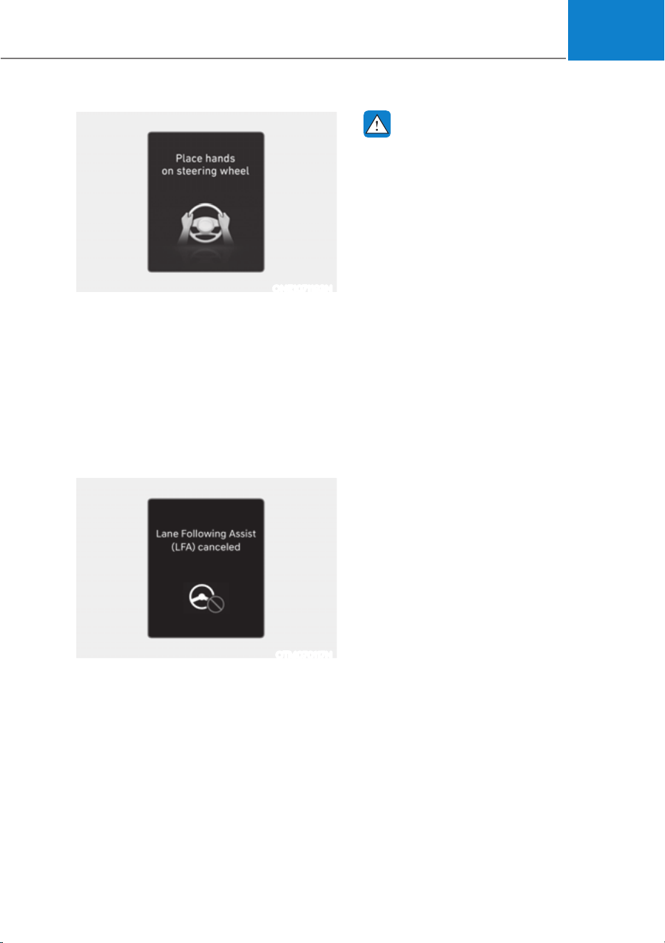
07
7-99
ONE1071193N
Hands-off warning
If the driver takes their hands off the
steering wheel for several seconds, the
‘Place hands on the steering wheel’
warning message will appear and an
audible warning will sound in stages.
First stage : Warning message
Second stage : Warning message (red
steering wheel) and
audible warning
OTM070117N
If the driver still does not have their
hands on the steering wheel after the
hands-off warning, the ‘Lane Following
Assist (LFA) canceled’ warning message
will appear and Lane Following Assist will
be automatically canceled.
WARNING
ś The steering wheel may not be
assisted if the steering wheel is held
very tight or the steering wheel is
steered over a certain degree.
ś Lane Following Assist does not
operate at all times. It is the
responsibility of the driver to safely
steer the vehicle and to maintain the
vehicle in its lane.
ś The hands–off warning message
may appear late depending on road
conditions. Always have your hands
on the steering wheel while driving.
ś If the steering wheel is held very
lightly the hands–off warning
message may appear because Lane
Following Assist may not recognize
that the driver has their hands on the
steering wheel.
ś If you attach objects to the steering
wheel, the hands-off warning may
not work properly.
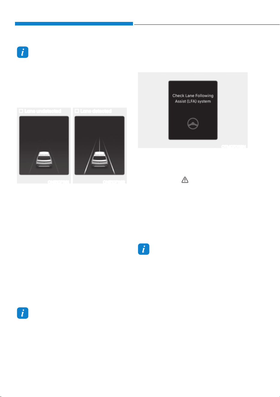
Driver Assistance System
7-100
Information
ś For more details on setting the
functions in the infotainment system,
refer to “Vehicle Settings” section in
chapter 4.
ś When both lane markings are detected,
the lane lines on the cluster will change
from grey to white.
Lane undetected Lane detected
ONE1071161 ONE1071162
ś The images and colors in the cluster
may differ depending on the cluster
type or theme selected from the
cluster.
ś If lane markings are not detected,
steering wheel control by Lane
Following Assist can be limited
depending on whether a vehicle is in
front or the driving conditions of the
vehicle.
ś Even though the steering is assisted
by Lane Following Assist, the driver
may control the steering wheel.
ś The steering wheel may feel heavier
or lighter when the steering wheel is
assisted by Lane Following Assist than
when it is not.
Information
The images or colors may be displayed
differently depending on the specifications
of the instrument panel or theme.
Lane Following Assist
Malfunction and Limitations
Lane Following Assist malfunction
OTM070118N
When Lane Following Assist is not
working properly, the ‘Check Lane
Following Assist (LFA) system’ warning
message will appear for several seconds,
and the master (
) warning light
illuminates on the cluster. If it occurs,
have the vehicle be inspected by an
authorized HYUNDAI dealer.
Limitations of Lane Following Assist
For more details on Lane Following Assist
limitations, refer to “Lane Keeping Assist
(LKA)” section in this chapter.
Information
For more details on Lane Following Assist
precautions, refer to “Lane Keeping Assist
(LKA)” section in this chapter.
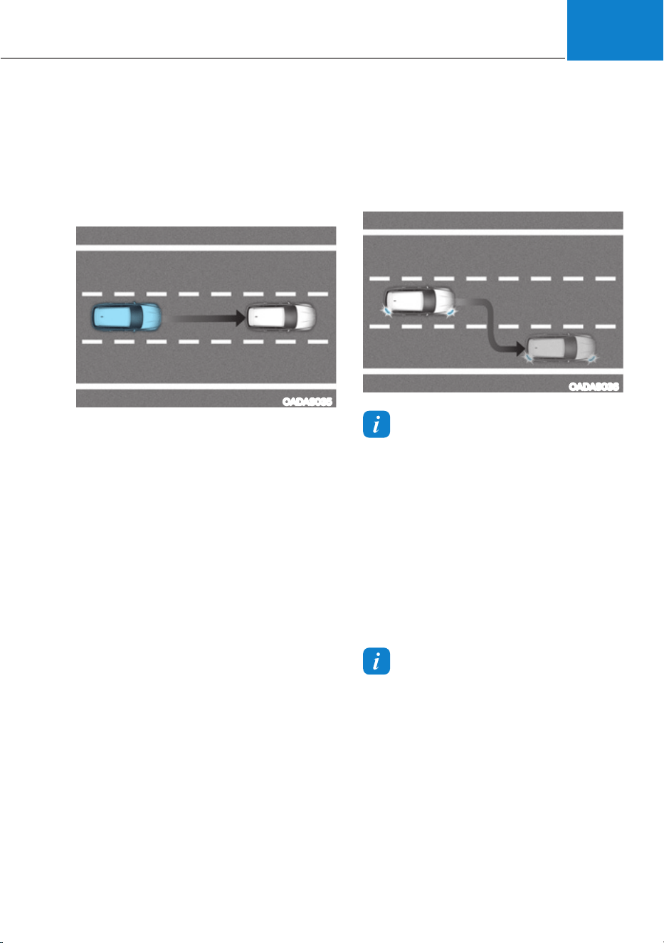
07
7-101
Basic function
Highway Driving Assist is designed to
help detect vehicles and lanes ahead,
and help maintain distance from the
vehicle ahead, maintain the set speed,
and help center the vehicle in the lane
while driving on the highway.
OADAS035
Highway Lane Change Assist (if equipped)
Highway Lane Change Assist function
helps change lanes to the direction the
driver slightly moves the turn signal
switch if the function judges that lane
change is possible.
OADAS036
Information
ś Highway Driving Assist is available
only on controlled access road of
certain highways. (except for the
interchange/junction)
à Controlled access road indicates
roads with limited entrances and
exits that allow uninterrupted high
speed traffic flow. Only passenger
cars and motorcycles are allowed on
controlled access roads.
ś Additional highways may be expanded
by future navigation updates.
Information
Highway Driving Assist operates on main
roads of highways, and does not operate
on interchange or junctions.
+,*+:$<'5,9,1*$66,67ǣ+'$Ǥǣ,)(48,33('Ǥ
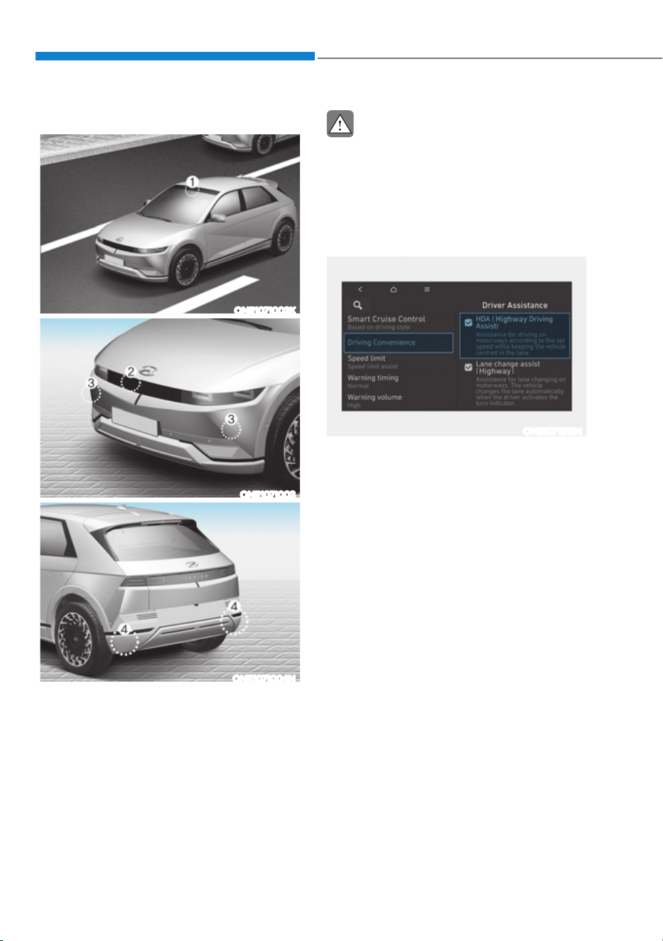
Driver Assistance System
7-102
Detecting sensor
ONE1071002K
ONE1071003
ONE1071004N
[1] : Front view camera, [2]: Front radar,
[3] : Front corner radar (if equipped),
[4] : Rear corner radar (if equipped)
Refer to the picture above for the
detailed location of the detecting
sensors.
CAUTION
For more details on the precautions of
the detecting sensors, refer to “Forward
Collision-Avoidance Assist (FCA)”
section in this chapter.
Highway Driving Assist Settings
Setting features
ONE1071213N
Basic function
With the vehicle on, select or
GHVHOHFWœ'ULYHU$VVLVWDQFHƟ'ULYLQJ
Convenience’ from the Settings menu to
set whether to use each function.
- If ‘Highway Driving Assist’ is selected,
it helps maintain distance from the
vehicle ahead, maintain the set speed,
and helps center the vehicle in the
lane.
Highway Lane Change Assist (if equipped)
- If ‘Highway Lane Change Assist’ is
selected, it helps the driver change
lanes.
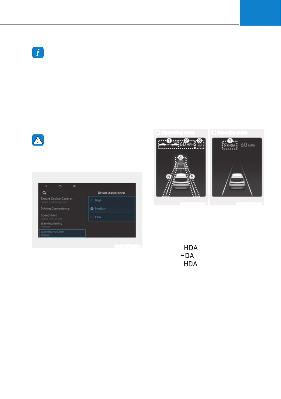
07
7-103
Information
ś When ‘Highway Driving Assist’ is
deselected, the setting for ‘Highway
Lane Change Assist’ cannot be
changed.
ś If there is a problem with the functions,
the settings cannot be changed.
Have the vehicle be inspected by an
authorized HYUNDAI dealer.
ś If the vehicle is restarted, the functions
will maintain the last setting.
WARNING
For your safety, change the Settings
after parking the vehicle at a safe
location.
ONE1071202N
Warning Volume
With the vehicle on, select ‘Driver
$VVLVWDQFHƟ:DUQLQJ9ROXPHŔIURPWKH
Settings menu to change the Warning
Volume to ‘High’, ‘Medium’ or ‘Low’ for
Highway Driving Assist.
If you change the warning volume,
the Warning Volume of other Driver
Assistance systems may change.
Highway Driving Assist
Operation
Basic function
Display and control
You can see the status of the Highway
Driving Assist operation in the Driving
Assist view on the cluster. Refer to “View
Modes” section in chapter 4.
Highway Driving Assist will be displayed
as below depending on the status of the
function.
Operating state Standby state
ONE1071103N ONE1071104N
(1) Highway Driving Assist indicator,
whether there is a vehicle ahead
and the selected distance level are
displayed.
à Highway Driving Assist indicator
- Green
: Operating state
-Grey
: Standby state
- White
blink: Accelerator
depressed state
(2) Set speed
(3) Lane Following Assist indicator
(4) Whether there is a vehicle ahead and
the selected headway
(5) Whether the lane is detected or not

Driver Assistance System
7-104
Information
For more details on the display refer to
“Smart Cruise Control (SCC)” and “Lane
Following Assist (LFA)” sections in this
chapter.
Highway Driving Assist operating
Highway Driving Assist operates when:
ś Driving on the main road of highways,
and turning on Highway Driving Assist
by pressing the Driving Assist (
)
button.
ś Entering the main road of highways
while Lane Following assist and Smart
Cruise Control are operating
Information
ś While driving on the highway, if
Smart Cruise Control starts operating,
Highway Driving Assist will operate.
ś When entering the main roads of
highways while Smart Cruise Control is
operating, Driving Assist will not turn
on if Lane Following Assist is turned
off.
ś Restarting after stopping
OTM070114L
When Highway Driving Assist is
operating, your vehicle will stop if the
vehicle ahead of you stops. Also, if the
vehicle ahead of you starts moving
within 30 seconds after the stop, your
vehicle will start as well. In addition,
after the vehicle has stopped and 30
seconds have passed, the ‘Use switch
or pedal to accelerate’ message
will appear on the cluster. Depress
the accelerator pedal or push the +
switch, - switch or
switch to start
driving.
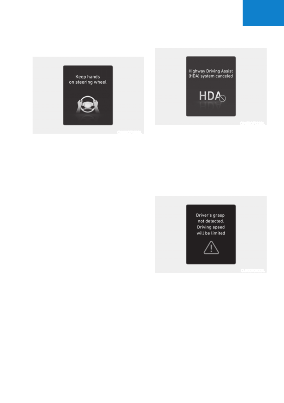
07
7-105
ś Hands-off warning
ONE1071193L
If the driver takes their hands off the
steering wheel for several seconds,
the ‘Place hands on the steering
wheel’ warning message will appear
and an audible warning will sound in
stages.
First stage : Warning message
Second stage : Warning message (red
steering wheel) and
audible warning
ONE1071216L
If the driver still does not have their
hands on the steering wheel after
the hands-off warning, the ‘Highway
Driving Assist (HDA) canceled’
warning message will appear and
Highway Driving Assist and Lane
Change Assist will be automatically
canceled.
ś Driving speed limit
OJK070103L
When Highway Driving Assist is
canceled by the hands-off warning,
The driving speed will be limited.
While Driving Speed Limit function
is operating, the ‘Driver’s grasp
not detected. Driving speed will be
limited’ warning message will appear
on the cluster, and an audible warning
will sound continuously.
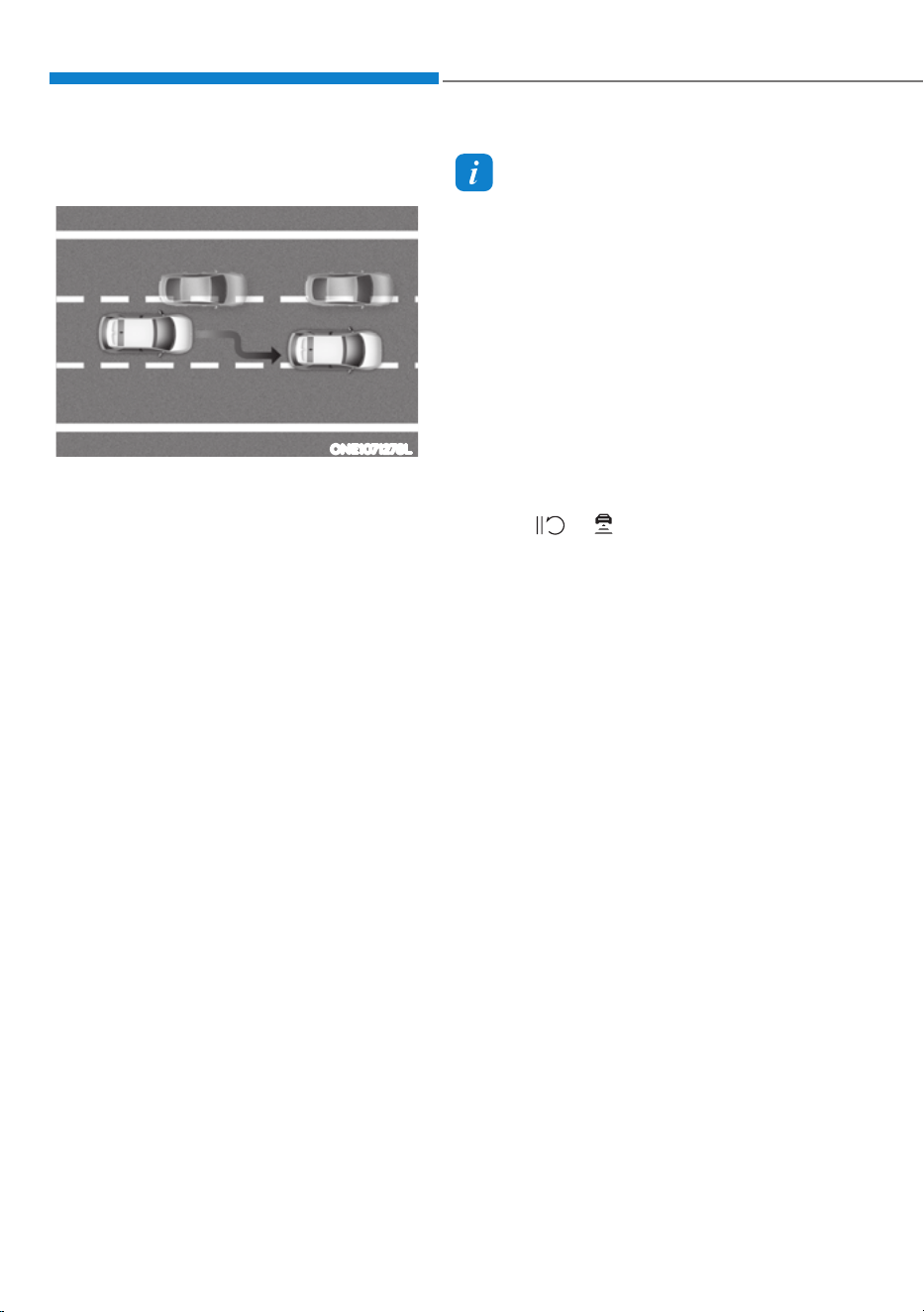
Driver Assistance System
7-106
ś Driving to one side within lane (if
equipped)
ONE1071278L
When vehicle speed is above 40 mph
(60 km/h), if a vehicle around you
is driving at a close distance, your
vehicle will control steering in the
opposite direction of the vehicle to
assist in safe driving.
If there are vehicles in both sides
of the lane that are driving close to
you, the function will not veer to the
opposite side of the lane.
Highway Driving Assist standby
When the Smart Cruise Control is
temporarily canceled while Highway
Driving Assist is operating, Highway
Driving Assist will be in the standby state.
At this time, Lane Following Assist will
operate properly.
Information
ś Driving Speed Limit helps you drive
below 40 mph (60 km/h). At this time,
the vehicle decelerates due to the
vehicle ahead. After the vehicle has
decelerated, it cannot automatically
accelerate.
ś Driving Speed Limit will cancel in the
following circumstances:
- When the driver grabs the steering
wheel again
- When the driver turns on Lane
Following Assist by pressing the Lane
Driving Assist button
- When Smart Cruise Control switch
+, -,
or button is pushed, or
the accelerator pedal or the brake
pedal is depressed
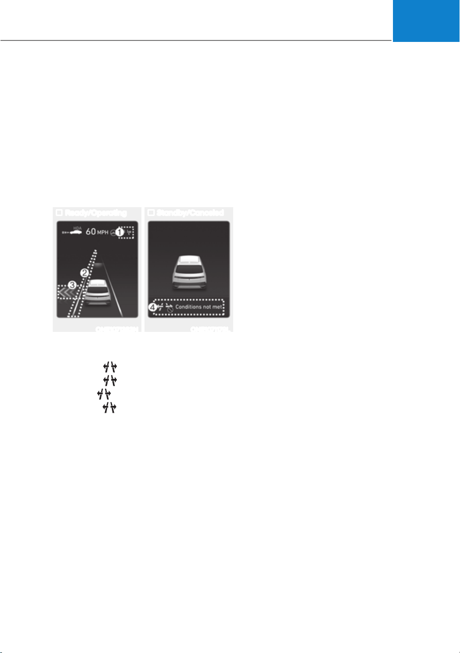
07
7-107
Highway Lane Change Assist (if
equipped)
Display and control
You can see the status of the Highway
Lane Change Assist function operation
in the Driving Assist view on the cluster.
Refer to “View Modes” section in chapter
4.
Highway Lane Change Assist function
will be displayed as below depending on
the status of the function.
Ready/Operating Standby/Canceled
ONE1071283N ONE1071179L
(1) Highway Lane Change Assist
indicator
śGreen
on : Ready state
śGreen
blink : Operating state
śGrey
on : Standby state
śWhite
blink : Canceled state
(2) Lane line
The lane line is displayed in the same
way as the Highway Lane Change
Assist indicator (1) above. However,
if the function is in the standby state,
it displays whether the lane line is
recognized or not.
(3) Green arrow and shade
The green arrow is displayed when a
certain amount of time has passed
after the function has started
operating, and until the lane change
has completed.
(4) Message
śMessage is displayed when the
function does not operate even
though the turn signal lever is used.
śMessage is displayed when
the function is canceled while
operating.
To turn on Highway Lane Change Assist
Highway Lane Change Assist function
will turn on when the following
conditions are satisfied.
ś The Driving Assist button or Lane
Driving Assist button is used to turn
on Highway Driving Assist.
Highway Lane Change Assist ready to
operate
While Highway Lane Change Assist
function is on, the function will be
ready to operate when all the following
conditions are satisfied:
ś Highway Driving Assist is operating
ś Lane Following Assist is operating
ś A vehicle in the rear area of your
vehicle is detected more than once
after the vehicle is turned on
ś Your vehicle speed is above 40 mph
(60 km/h)
ś Hands-off warning is not displayed on
the cluster
ś Hazard warning flasher is off
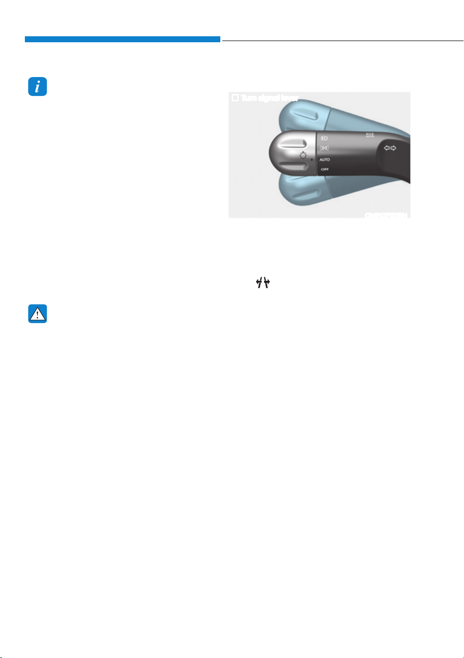
Driver Assistance System
7-108
Information
ś While Lane Change Assist function
is turned on (indicator on), Lane
Following Assist will not cancel even
if the turn signal indicator or hazard
warning flasher is operating.
ś Lane Change Assist function turns
off automatically when driven in the
following road conditions:
- One driving lane
- A road with no structure, such as a
medium strip, guardrails, etc.
- There is a pedestrian or cyclist on the
road ahead
ś When the function is in the ready state,
and vehicle speed is below 35 mph (55
km/h), the function will change to the
standby state.
WARNING
When Highway Lane Change Assist
function turns off while operating,
steering assist will be temporarily
canceled. Always be cautious while
driving.
Highway Lane Change Assist operating
Turn signal lever
ONE1071276N
[1] : Center
Highway Lane Change Assist function
will operate, when you push the turn
signal lever up or down to the A or B
position while the function is in the ready
state (
indicator is green), and all of
the following conditions are satisfied:
ś The driver has his/her hand on the
steering wheel
ś There is no collision risk in the
direction of lane change
ś There is a single dotted lane line in the
direction of lane change
ś There are no Forward Collision-
Avoidance Assist and Blind Spot
Collision-Avoidance Assist warnings
ś The vehicle is driven in the middle of
the lane (should not be driving close
to one side of the lane)
ś The road you are driving on, or the
road you are about to change lane is a
road that the function can operate

07
7-109
Information
ś When the turn signal lever is placed at A
When the turn signal lever is placed at
A position, the Highway Lane Change
Assist function is performed. After
that, if the turn signal lever is placed in
neutral, Highway Lane Change Assist
function is canceled before stepping on
the lane.
The Highway Lane Change Assist
function is not canceled after stepping
on the lane, but when the lane change
is completed, it is canceled and the turn
signal turns off.
ś When the turn signal lever is placed at
B position for a certain period of time,
the green arrow will appear. At this
time, even when the lever is released
and returns to it’s original position (1),
lane change will still be assisted.
While lane change is being made by the
function, the turn signal indicator will
blink even when the turn signal lever is
not held, and the turn signal indicator
will turn off when lane change is
complete.
Highway Lane Change Assist standby
Highway Lane Change Assist function
will be in the standby state when one of
the ready state condition is not satisfied,
or when entering or driving on one of the
following roads:
ś Road within a certain distance from
the tollgate on the main road of the
highway
ś The road ahead ends without an
interchange or junction
ś Road with sharp curves
ś Road with narrow lanes
Highway Lane Change Assist cancel
The function will be canceled when:
ś · When the turn signal lever is moved
to A and placed in neutral before
stepping on the lane while the
Highway Lane Change Assist function
is operating
ś The turn signal lever is turned on in
the opposite direction of lane change
ś The steering wheel is steered sharply

Driver Assistance System
7-110
WARNING
ś While Highway Driving Assist is
operating, the function will cancel if
one of the following occurs:
- Highway Driving Assist is turned
off
- Lane Following Assist or Smart
Cruise Control is turned off or
temporarily canceled
- Hands-off warning message is
displayed on the cluster
- The hazard warning flasher is
turned on
- Forward Collision-Avoidance
Assist or Blind-Spot Collision-
Avoidance Assist warning message
is displayed
- Possible collision is detected in the
next lane, even though there are
no Forward Collision-Avoidance
Assist and Blind Spot Collision-
Avoidance Assist warning
- The target lane to make a lane
change disappears
- The target lane to make a lane
change is not detected
- There is a problem with turn signal
lamps
- Highway Lane Change Assist
function is off (The function turns
off when the function is turned off
from the settings menu, when the
road changes to a one-way road,
when there is a intersection or
crosswalk ahead, when you enter
a road with no structure, such as
a medium strip, guardrail, etc.,
or when there is a pedestrian or
cyclist on the driving lane.)
- Your vehicle speed is below 35
mph (55 km/h)
ś While the function is operating,
when the function is canceled,
depending on the driving conditions,
the vehicle may drive to the middle
of the driving lane or steering assist
may stop. Always pay attention to
road and driving conditions while
driving.
ś The function may not operate
properly on roads with pedestrians
or cyclists, such as an intersection
or crosswalk. Always pay attention
to road and driving conditions while
driving.
Information
The images or colors may be displayed
differently depending on the specifications
of the instrument panel or theme.
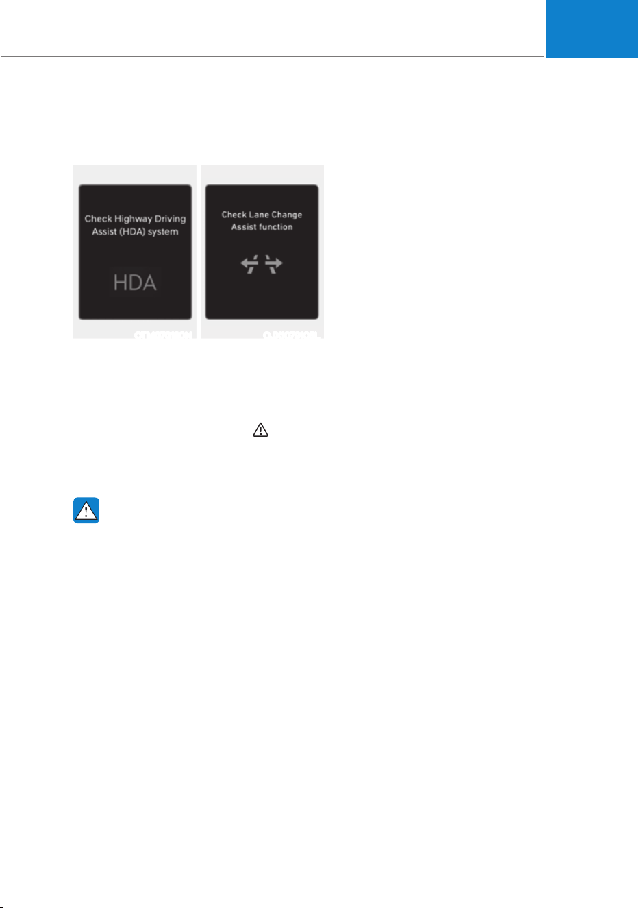
07
7-111
Highway Driving Assist
Malfunction and Limitation
Highway Driving Assist malfunction
OTM070120N OJX1079105L
When Highway Driving Assist or
Highway Lane Change function is not
working properly, the ‘Check Highway
Driving Assist (HDA) system’ or ‘Check
Lane Change Assist function’ warning
message will appear, and the
warning
light will illuminate on the cluster.
Have the vehicle be inspected by an
authorized HYUNDAI dealer.
WARNING
ś The driver is responsible for
controlling the vehicle for safe
driving.
ś Always have your hands on the
steering wheel while driving.
ś Highway Driving Assist is a
supplemental function that assists
the driver in driving the vehicle
and is not a complete autonomous
driving system. Always check road
conditions, and if necessary, take
appropriate actions to drive safely.
ś Always have your eyes on the road,
and it is the responsibility of the
driver to avoid violating traffic laws.
The vehicle manufacturer is not
responsible for any traffic violation
or accidents caused by the driver.
ś Highway Driving Assist may not
be able to recognize all traffic
situations. Highway Driving Assist
may not detect possible collisions
due to limitations of the function.
Always be aware of the limitations
of the function. Obsatcles (vehicles,
motorcycles, bicycles, pedestrians,
unspecified objects, structures,
etc.) that may collide with a vehicle
may not be detected.
ś Highway Driving Assist will turn off
automatically under the following
situations:
- Driving on roads that Highway
Driving Assist does not operate,
such as a rest area, intersection,
junction, etc.
- The navigation does not operate
properly such as when the
navigation is being updated or
restarted
ś Highway Driving Assist may
inadvertently operate or turn off
depending on road conditions
(navigation information) and
surroundings.
ś Lane Following Assist function may
be temporarily disabled when the
front view camera cannot detect
lanes properly or the hands-off
warning is on.
ś You may not hear the warning sound
of Highway Driving Assist if the
surrounding is noisy.

Driver Assistance System
7-112
ś If the vehicle is driven at high speed
above a certain speed at a curve,
your vehicle may drive to one side or
may depart from the driving lane.
ś When you are towing a trailer or
another vehicle, turn off Highway
Driving Assist for safety reasons.
ś The hands–off warning message
may appear early or late depending
on how the steering wheel is held or
road conditions. Always have your
hands on the steering wheel while
driving.
ś For your safety, please read the
owner's manual before using the
Highway Driving Assist.
ś Highway Driving Assist will not
operate when the vehicle is started,
or when the detecting sensors or
navigation is being initialized.
Limitations of Highway Driving
Assist
Highway Driving Assist and Highway
Lane Change Assist (if equipped) may
not operate normally, or may not operate
under the following circumstances:
ś The map information and the
actual road is different because the
navigation is not updated
ś The map information and the actual
road is different because of real-time
GPS data or map information error
ś The infotainment system is overloaded
by simultaneously performing
functions such as route search, video
playback, voice recognition, etc.
ś GPS signals are blocked in areas such
as a tunnel
ś The driver goes off course or the
route to the destination is changed or
canceled by resetting the navigation
ś The vehicle enters a service station or
rest area
ś Android Auto or Car Play is operating
ś The navigation cannot detect the
current vehicle position (for example,
elevated roads including overpass
adjacent to general roads or nearby
roads exist in a parallel way)
ś White single dotted lane line or road
edge cannot be detected
ś The road is temporarily controlled due
to construction, etc.
ś There is no structure, such as a
medium strip, guardrails, etc., on the
road
ś There is a changeable lane in the
direction of lane change
Information
For more details on the limitations of
the front view camera, front radar, front
corner radar and rear corner radar, refer
to “Forward Collision-Avoidance Assist
(FCA)” section in this chapter.
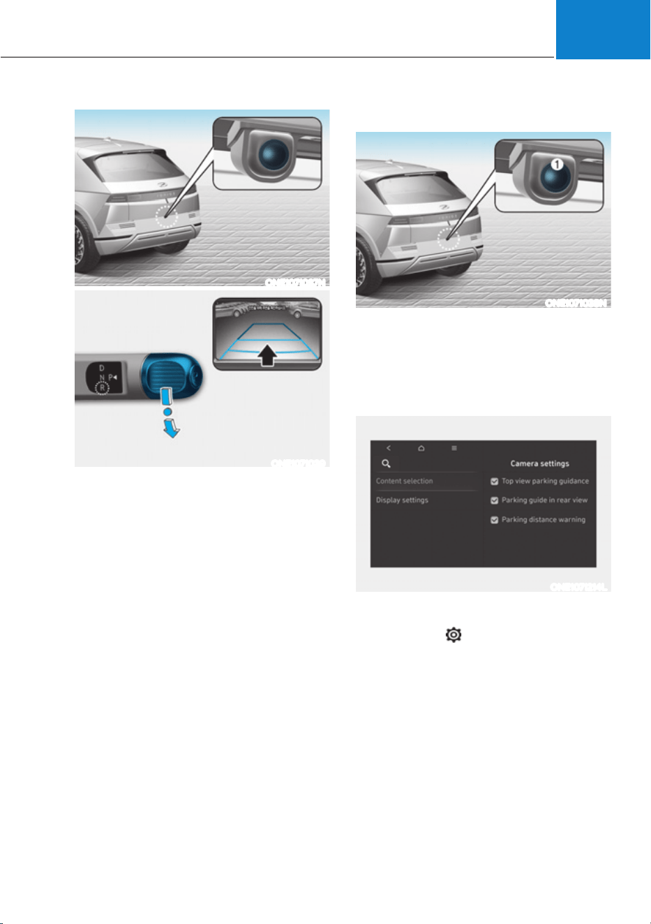
07
7-113
ONE1071037N
ONE1071039
Rear View Monitor shows the area
behind the vehicle to assist you when
parking or backing up.
Detecting sensor
ONE1071038N
[1] : Rear view camera
Refer to the picture above for the
detailed location of the detecting sensor.
Rear View Monitor Settings
Camera settings
ONE1071214L
ś You can change Rear View Monitor
‘Display Contents’ by touching the
setup icon (
) on the screen while
Rear View Monitor is operating, or
VHOHFWLQJœ'ULYHU$VVLVWDQFHƟ3DUNLQJ
6DIHW\Ɵ&DPHUD6HWWLQJVŔIURPWKH
Settings menu while the vehicle is on.
ś To use Rear View while Driving, select
&DPHUD6HWWLQJVƟ'LVSOD\&RQWHQWVƟ
Keeps Rear Camera' from the Settings
menu while the vehicle is on.
ś In the Display Contents, you can
change setting for 'Rear View' and
in the Display Settings, you can
change the screen's 'Brightness' and
'Contrast'.
5($59,(:021,725ǣ590Ǥǣ,)(48,33('Ǥ
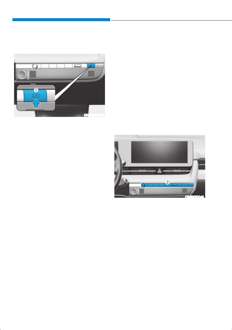
Driver Assistance System
7-114
Rear View Monitor Operation
Operating button
ONE1071040
Parking/View button
Press the Parking/View button (1) to turn
on Rear View Monitor.
Press the button again to turn off the
function.
Rear view
Operating conditions
ś Shift the gear to R (Reverse), the
image will appear on the screen.
ś Press the Parking/View button (1)
while the gear is in P (Park), the image
will appear on the screen.
Off conditions
ś The rear view cannot be turned off
when the gear is in R (Reverse).
ś Press the Parking/View button (1)
again while the gear is in P (Park) with
the rear view on the screen, the rear
view will turn off.
ś Shift the gear from R (Reverse) to P
(Park), the rear view will turn off.
Extended Rear View function
The rear view will maintain showing on
the screen to help you when parking.
Operating conditions
Shift the gear from R (Reverse) to N
(Neutral) or D (Drive), the rear view will
appear on the screen.
Off conditions
ś When vehicle speed is above 6 mph
(10 km/h), the rear view will turn off.
ś Shift the gear to P (Park), the rear view
will turn off.
Rear view while driving
ONE1071041
The driver is able to check the rear view
on the screen while driving, it is to assist
with backing up.
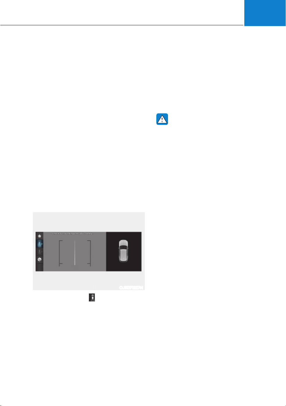
07
7-115
Operating conditions
Press the Parking/View button (1) while
the gear is in D (Drive) or N (Neutral),
the driving rear view will appear on the
screen.
Off conditions
ś Press the Parking/View button (1)
again, the driving rear view will turn
off.
ś Press one of the infotainment system
button (2), the driving rear view will
turn off.
ś Shift the gear to P (Park), the driving
rear view will turn off.
When operating
If the gear is shifted to R (Reverse), while
Driving rear view is displayed on the
screen, the screen will change to rear
view with parking guidance.
Rear top view
OJK071227N
When you touch the icon, the top view
is displayed on the screen and shows the
distance from the vehicle in the back of
your vehicle while parking.
Rear View Monitor Malfunction
and Limitations
Rear View Monitor malfunction
When Rear View Monitor is not working
properly, or the screen flickers, or the
camera image does not display properly,
Have the vehicle be inspected by an
authorized HYUNDAI dealer.
WARNING
ś The rear view camera does not
cover the complete area behind the
vehicle. The driver should always
check the rear area directly through
the inside and outside side view
mirror before parking or backing up.
ś The image shown on the screen may
differ from the actual distance of the
object. Make sure to directly check
the vehicle's surroundings for safety.
ś Always keep the rear view camera
lens clean. If the lens is covered with
foreign material, it may adversely
affect camera performance and
Rear View Monitor may not operate
properly. However, do not use
chemical solvents such as strong
detergents containing high alkaline
or volatile organic solvents (gasoline,
acetone, etc.). This may damage the
camera lens.
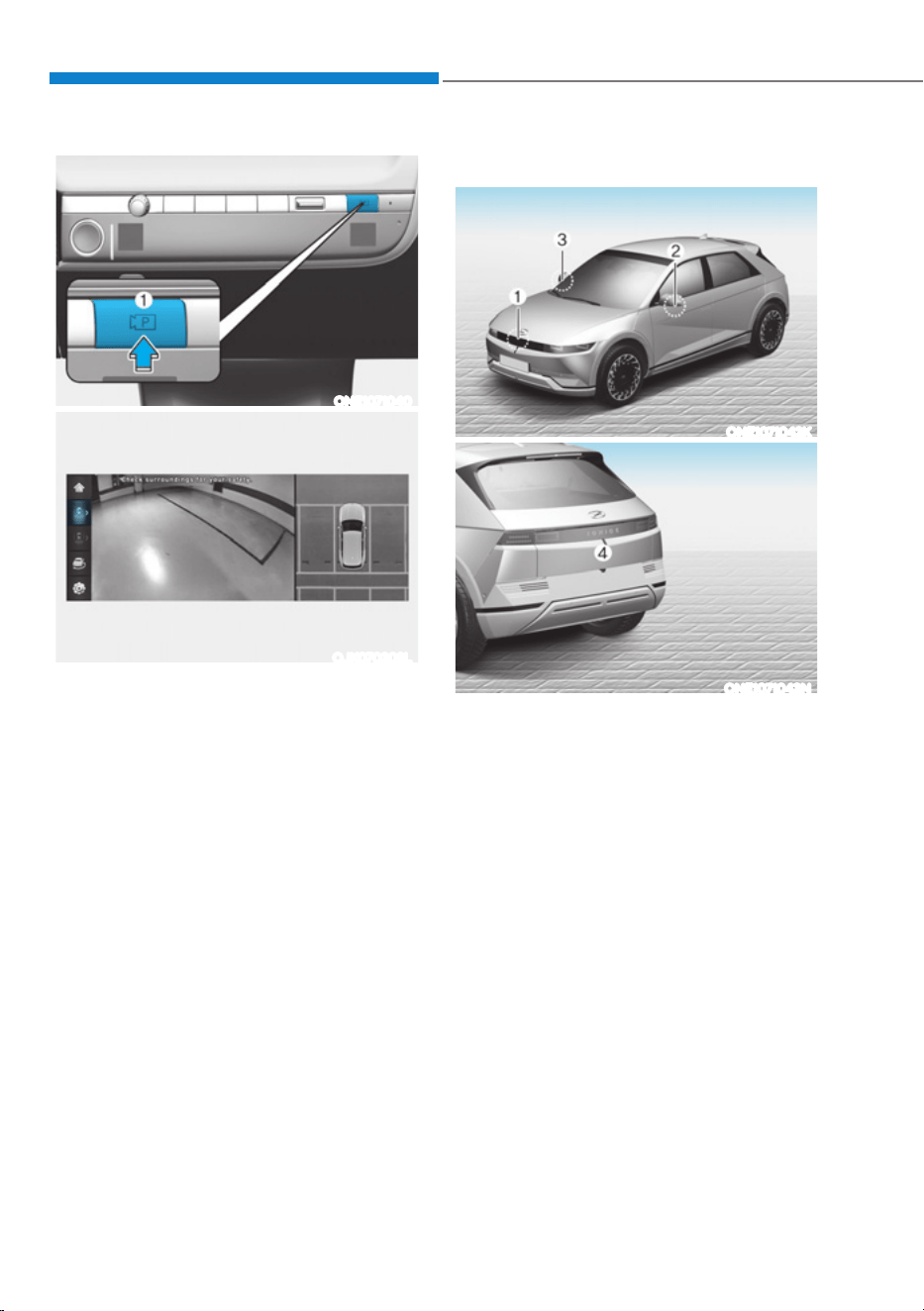
Driver Assistance System
7-116
ONE1071040
OJK070203L
Surround View Monitor can assist in
parking by allowing the driver to see
around the vehicle.
Detecting sensor
ONE1071042K
ONE1071043N
[1] : Surround-front view camera,
[2],[3] : Surround-side view camera
(under the side view mirror),
[4] : Surround-rear view camera
Refer to the picture above for the
detailed location of the detecting
sensors.
6855281'9,(:021,725ǣ690Ǥǣ,)(48,33('Ǥ
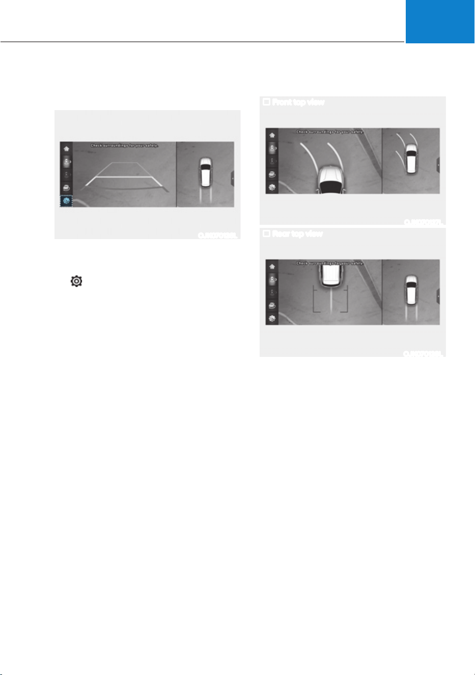
07
7-117
Surround View Monitor Settings
Camera settings
OJK070126L
ś You can change Surround View
Monitor ‘Display Contents’ or ‘Display
Settings’ by touching the setup icon
(
) on the screen while Surround
View Monitor is operating, or selecting
œ'ULYHU$VVLVWDQFHƟ3DUNLQJ6DIHW\Ɵ
Camera Settings’ from the Settings
menu while the vehicle is on.
ś In the Display Contents, you can
change settings for ‘Top View Parking
Guidance’, ‘Rear View Parking
Guidance’ and ‘Parking Distance
Warning’.
Top View Parking Guidance
Front top view
OJK070127L
Rear top view
OJK070128L
ś When the ‘Top View Parking Guidance’
is selected, parking guidance is
displayed on the right side of the
Surround View Monitor screen.
ś The ‘Top View Parking Guidance’ can
be connected with the front top view
parking guidance or the rear top view
parking guidance.
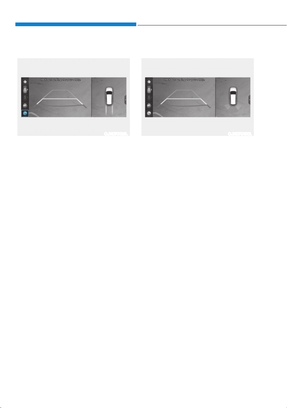
Driver Assistance System
7-118
Rear View Parking Guidance
OJK070126L
ś When the ‘Rear View Parking
Guidance’ is selected, parking
guidance is displayed in the rear view.
ś The horizontal guideline of the Rear
View Parking Guidance shows the
distance of 1.6 ft. (0.5 m), 3.3 ft. (1 m)
and 7.6 ft. (2.3 m) from the vehicle.
Parking Distance Warning
OJK070130L
ś When the ‘Parking Distance Warning’
is selected, parking distance warning
is displayed on the right side of the
Surround View Monitor screen.
ś The image will be displayed only when
Parking Distance Warning is warning
the driver.
Surround View Monitor Auto On
With the vehicle on, select ‘Driver
$VVLVWDQFHƟ3DUNLQJ6DIHW\Ɵ6XUURXQG
View Monitor Auto On’ from the Settings
menu to use the function.
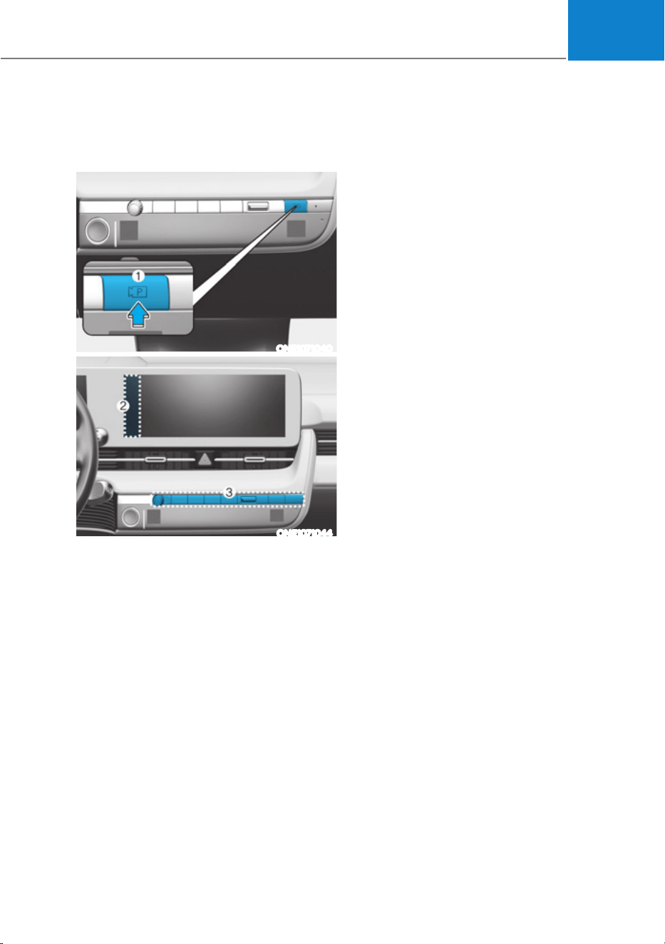
07
7-119
Surround View Monitor
Operation
Operating button
ONE1071040
ONE1071044
ś Press the Parking/View button (1) to
turn on Surround View Monitor.
Press the button again to turn off the
function.
ś Other view modes can be selected
by touching the view icons (2) on the
Surround View Monitor screen.
ś When one of the infotainment system
button (3) is pressed without the gear
in R (Reverse), Surround View Monitor
will turn off.
Front view
The front image is displayed on the
screen when the gear is in N (Neutral) or
D (Drive) to assist in parking. The front
view has a top view/front view/side
view/3D view.
Operating conditions
ś When the gear is shifted from R
(Reverse) to N (Neutral) or D (Drive),
the last set mode of front view
function will be selected.
ś Front view function will operate when
the following conditions are satisfied:
- While the infotainment system
screen is being displayed, press the
Parking/View button (1) briefly when
the gear is in D (Drive) or N (Neutral)
and vehicle speed is below 6 mph
(10 km/h).
ś Surround View Monitor Auto On
function will operate when the
following conditions are satisfied:
- :LWKœ'ULYHU$VVLVWDQFHƟ3DUNLQJ
6DIHW\Ɵ6XUURXQG9LHZ0RQLWRU
Auto On’ selected from the Settings
menu, the front parking assist view
screen is displayed when Parking
Distance Warning warns the driver
while driving in D (Drive).

Driver Assistance System
7-120
Off conditions
ś Press the Parking/View button (1)
again, the image will turn off.
ś When vehicle speed is above 6 mph
(10 km/h) with the gear in D (Drive),
Surround View Monitor will turn off
and the screen will change back to the
previous infotainment system screen.
Although you drive below 6 mph (10
km/h) again, Surround View Monitor
will not turn on.
ś Press one of the infotainment system
button (3), the screen will change to
the infotainment system screen.
ś Shift the gear to P (Park), the image
will turn off.
Rear view
The rear image is displayed on the screen
when the gear is in P (Park) to assist in
parking. The rear view has a top view/
rear view/side view/3D view.
Operating conditions
ś Shift the gear to R (Reverse), the
image will appear on the screen.
ś Press the Parking/View button (1)
while the gear is in P (Park), the image
will appear on the screen.
Off conditions
ś The image cannot be turned off when
the gear is in R (Reverse).
ś Shift the gear from R (Reverse) to P
(Park), the image will turn off.
ś Press the Parking/View button (1)
again while the gear is in P (Park) with
the image on the screen.

07
7-121
Surround View Monitor
Malfunction and Limitations
Surround View Monitor malfunction
When Surround View Monitor is not
working properly, or the screen flickers,
or the camera image does not display
properly, have the vehicle be inspected
by an authorized HYUNDAI dealer.
Limitations of Surround View
Monitor
ś The screen may be displayed
abnormally, and an icon will appear at
the top left side of the screen under
the following circumstances:
- The liftgate is opened
- The driver or front passenger door
is opened
- The side view mirror is folded
WARNING
ś ALWAYS look around your vehicle
to make sure there are no objects
or obstacles before moving the
vehicle. What you see on the screen
may differ from the actual vehicle’s
location.
ś The image shown on the screen may
differ from the actual distance of the
object. Make sure to directly check
the vehicle's surroundings for safety.
ś Surround View Monitor is designed
to be used on a flat surface.
Therefore, if used on roads with
different heights such as curbs
and speed bumps, the image in the
screen my not look correct.
ś Always keep the camera lens clean.
If the lens is covered with foreign
material, it may adversely affect
camera performance and Surround
View Monitor may not operate
properly. However, do not use
chemical solvents such as strong
detergents containing high alkaline
or volatile organic solvents (gasoline,
acetone, etc.). This may damage the
camera lens.
Information
ś When Rear View while Driving is on,
it stays on while driving regardless of
vehicle speed.
ś When Rear View while Driving is on
while backing up, the screen changes to
the rear view.
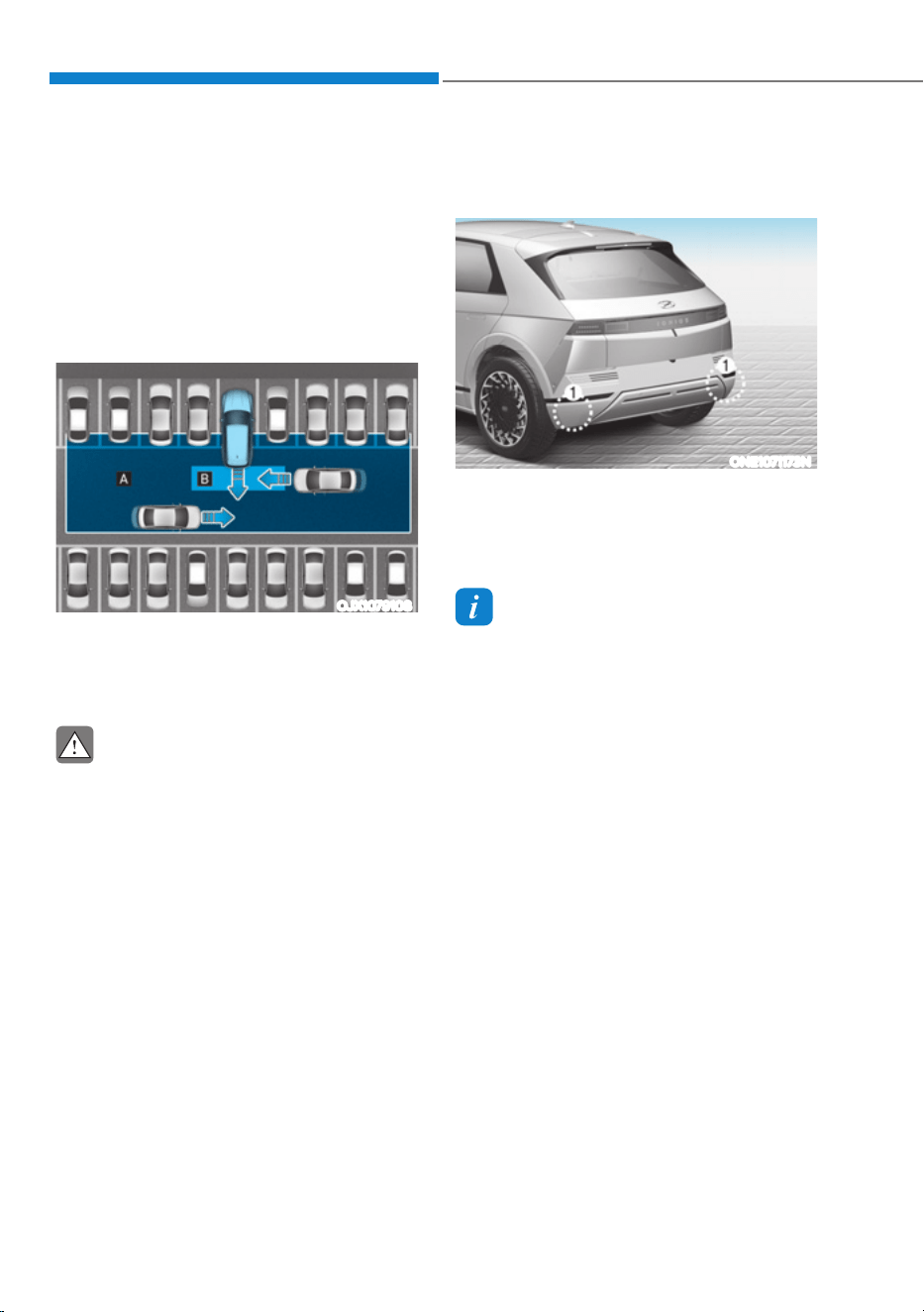
Driver Assistance System
7-122
Rear Cross-Traffic Collision-Avoidance
Assist is designed to help detect vehicles
approaching from the rear left and right
side while your vehicle is reversing,
and warn the driver that a collision is
imminent with a warning message and
an audible warning. Also, braking is
assisted to help prevent collision.
OJX1079108
[A] : Rear Cross-Traffic Collision Warning operating
range,
[B] : Rear Cross-Traffic Collision-Avoidance Assist
operating range
CAUTION
Warning timing may vary depending
on vehicle speed of the approaching
vehicle.
Detecting sensor
ONE1071173N
[1] : Rear corner radar
Refer to the picture above for the
detailed location of the detecting
sensors.
Information
For more details on the precautions of the
rear corner radar, refer to “Blind-Spot
Collision-Avoidance Assist (BCA)” section
in this chapter.
5($5&5266ǘ75$)),&&2//,6,21ǘ$92,'$1&($66,67
ǣ5&&$Ǥǣ,)(48,33('Ǥ

07
7-123
Rear Cross-Traffic Collision-
Avoidance Assist Settings
Setting features
ONE1071215L
Rear Cross-Traffic Safety
With the vehicle on, select ‘Driver
$VVLVWDQFHƟ3DUNLQJ6DIHW\Ɵ5HDU&URVV
Traffic Safety’ from the Settings menu
to turn on Rear Cross-Traffic Collision-
Avoidance Assist and deselect to turn off
the function.
WARNING
When the vehicle is restarted, Rear
Cross-Traffic Collision-Avoidance Assist
will always turn on. However, if ‘Off’ is
selected after the vehicle is restarted,
the driver should always be aware of
the surroundings and drive safely.
ONE1071282N
Warning Timing
With the vehicle on, select ‘Driver
$VVLVWDQFHƟ:DUQLQJ7LPLQJŔIURPWKH
Settings menu to change the initial
warning activation time for Rear Cross-
Traffic Collision-Avoidance Assist.
When the vehicle is first delivered,
Warning Timing is set to ‘Normal’. If you
change the Warning Timing, the Warning
Timing of other Driver Assistance
systems may change.
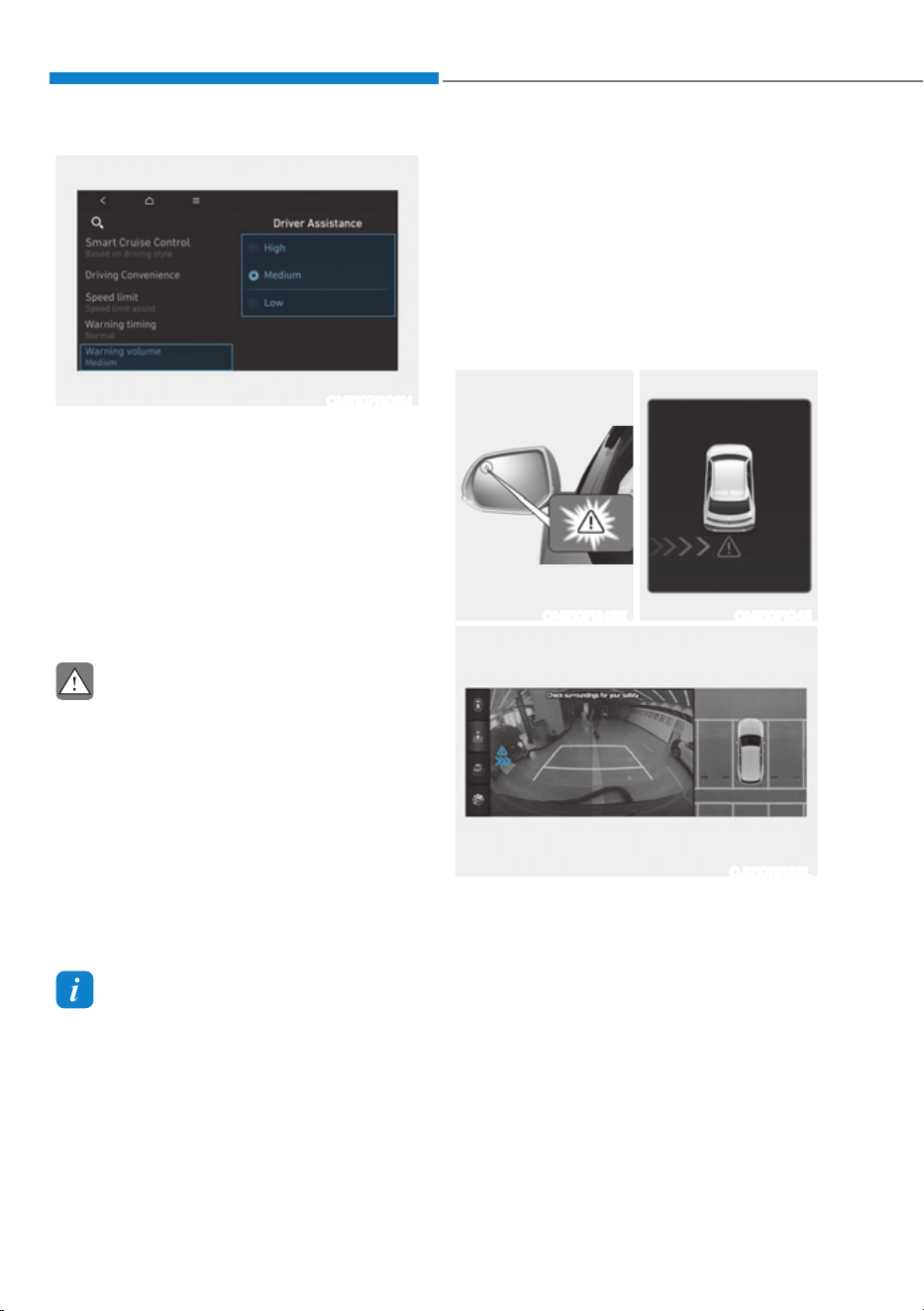
Driver Assistance System
7-124
ONE1071202N
Warning Volume
With the vehicle on, select ‘Driver
$VVLVWDQFHƟ:DUQLQJ9ROXPHŔIURPWKH
Settings menu to change the Warning
Volume to ‘High’, ‘Medium’ or ‘Low’ for
Rear Cross-Traffic Collision-Avoidance
Assist.
If you change the warning volume,
the Warning Volume of other Driver
Assistance systems may change.
CAUTION
ś The setting of the Warning Timing
and Warning Volume applies to
all functions of the Rear Collision-
Avoidance Assist.
ś Even though ‘Normal’ is selected for
Warning Timing, if a vehicle from the
left or right side approaches at high
speed, warning may seem late.
ś Select ‘Late’ for Warning Timing
when traffic is light and when driving
speed is slow.
Information
If the vehicle is restarted, Warning Timing
and Warning Volume will maintain the
last setting.
Rear Cross-Traffic Collision-
Avoidance Assist Operation
Warning and control
Rear Cross-Traffic Collision-Avoidance
Assist will warn and control the vehicle
depending on collision risk level:
‘Collision Warning’, ‘Emergency Braking’
and ‘Stopping vehicle and ending brake
control’.
ONE1071248K ONE1071045
OJX1079166L
Collision Warning
ś To warn the driver of an approaching
vehicle from the rear left/right side
of your vehicle, the warning light on
the side view mirror will blink and a
warning will appear on the cluster. At
the same time, an audible warning
will sound. If the Rear View Monitor is
operating, a warning will also appear
on the infotainment system screen.
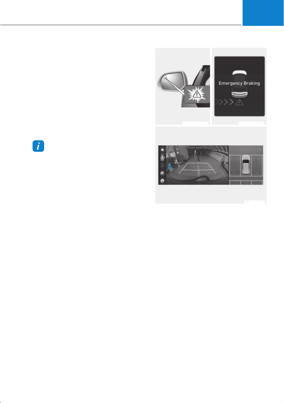
07
7-125
ś Rear Cross-Traffic Collision-Avoidance
Assist will operate when all the
following conditions are satisfied:
- The gear is shifted to R (Reverse)
- Vehicle speed is below 5 mph (8
km/h)
- The approaching vehicle is within
approximately 82 ft. (25 m) from the
left and right side of your vehicle
- The speed of the vehicle
approaching from the left and right
is above 3 mph (5 km/h)
Information
If the operating conditions are satisfied,
there will be a warning whenever the
vehicle approaches from the left or right
side even though your vehicle speed is
0 mph (0 km/h).
ONE1071248K ONE1071046L
OJK070131
Emergency Braking
ś To warn the driver of an approaching
vehicle from the rear left/right side
of your vehicle, the warning light on
the side view mirror will blink and a
warning message will appear on the
cluster. At the same time, an audible
warning will sound. A warning will also
appear on the infotainment system
screen.

Driver Assistance System
7-126
ś Rear Cross-Traffic Collision-Avoidance
Assist will operate when all the
following conditions are satisfied:
- The gear is shifted to R (Reverse)
- Vehicle speed is below 5 mph (8
km/h)
- The approaching vehicle is within
approximately 5 ft. (1.5 m) from the
left and right side of your vehicle
- The speed of the vehicle
approaching from the left and right
is above 3 mph (5 km/h)
ś Emergency braking will be assisted
to help prevent collision with
approaching vehicles from the left
and right.
WARNING
Brake control will end when:
- The approaching vehicle is out of the
detecting range
- The approaching vehicle passes
behind your vehicle
- The approaching vehicle does not
drive toward your vehicle
- The approaching vehicle speed slows
down
- The driver depresses the brake pedal
with sufficient power
ONE1071185L
Stopping vehicle and ending brake control
ś When the vehicle is stopped due
to emergency braking, the ‘Drive
carefully’ warning message will
appear on the cluster.
ś For your safety, the driver should
depress the brake pedal immediately
and check the surroundings.
ś Brake control will end after the vehicle
is stopped by emergency braking for
approximately 2 seconds.
ś During emergency braking, braking
control by Rear Cross-Traffic Collision-
Avoidance Assist will automatically
cancel when the driver excessively
depresses the brake pedal.

07
7-127
WARNING
Take the following precautions when
using Rear Cross-Traffic Collision-
Avoidance Assist:
ś For your safety, change the Settings
after parking the vehicle at a safe
location.
ś If any other system’s warning
message is displayed or audible
warning is generated, Rear Cross-
Traffic Collision-Avoidance Assist’s
warning message may not be
displayed and audible warning may
not be generated.
ś You may not hear the warning sound
of Rear Cross-Traffic Collision-
Avoidance Assist if the surrounding
is noisy.
ś Rear Cross-Traffic Collision-
Avoidance Assist may not operate if
the driver applies the brake pedal to
avoid collision.
ś During Rear Cross-Traffic Collision-
Avoidance Assist operation, the
vehicle may stop suddenly injuring
passengers and shifting loose
objects. Always have the seat belt on
and keep loose objects secured.
ś Even if there is a problem with Rear
Cross-Traffic Collision-Avoidance
Assist, the vehicle’s basic braking
performance will operate properly.
ś When Rear Cross-Traffic Collision-
Avoidance Assist is operating,
braking control by the function
will automatically cancel when the
driver excessively depresses the
accelerator pedal.
ś Rear Cross-Traffic Collision-
Avoidance Assist does not operate
in all situations or cannot avoid all
collisions.
ś Rear Cross-Traffic Collision-
Avoidance Assist may warn the
driver late or may not warn the driver
depending on the road and driving
conditions.
ś The driver should hold the
responsibility to control the vehicle.
Do not solely depend on Rear Cross-
Traffic Collision-Avoidance Assist.
Rather, maintain a safe braking
distance, and if necessary, depress
the brake pedal to reduce driving
speed or to stop the vehicle.
ś Never deliberately operate Rear
Cross-Traffic Collision-Avoidance
Assist on people, animal, objects,
etc. It may cause serious injury or
death.
CAUTION
The brake control may not operate
properly depending on the status of
ESC (Electronic Stability Control).
There will only be a warning when:
- The ESC (Electronic Stability Control)
warning light is on
- ESC (Electronic Stability Control) is
engaged in a different function
Information
If braking is assisted by Rear Cross-
Traffic Collision-Avoidance Assist, the
driver must immediately depress the brake
pedal and check vehicle surroundings.
- Brake control will end when the
driver depresses the brake pedal with
sufficient power.
- After shifting the gear to R (Reverse),
braking control will operate once for
left and right vehicle approach.
Information
The images or colors may be displayed
differently depending on the specifications
of the instrument panel or theme.
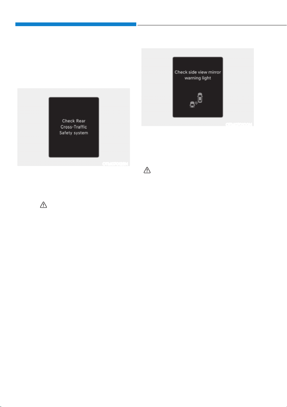
Driver Assistance System
7-128
Rear Cross-Traffic Collision-
Avoidance Assist Malfunction
and Limitations
Rear Cross-Traffic Collision-
Avoidance Assist malfunction
OTM070125N
When Rear Cross-Traffic Collision-
Avoidance Assist is not working properly,
the ‘Check Rear Cross-Traffic Safety
system’ warning message will appear on
the cluster for several seconds, and the
master (
) warning light will illuminate
on the cluster. If it occurs, have the
vehicle be inspected by an authorized
HYUNDAI dealer.
OTM070100N
When the side view mirror warning light
is not working properly, the ‘Check side
view mirror warning light’ (or ‘Check
outside mirror warning icon’) warning
message will appear on the cluster
for several seconds, and the master
(
) warning light will illuminate on the
cluster. If it occurs, have the vehicle be
inspected by an authorized HYUNDAI
dealer.

07
7-129
Rear Cross-Traffic Collision-
Avoidance Assist disabled
OTM070124N
When the rear bumper around the rear-
side radar or sensor is covered with
foreign material, such as snow or rain,
or installing a trailer or carrier, it can
reduce the detecting performance and
temporarily limit or disable Rear Cross-
Traffic Collision-Avoidance Assist.
If this occurs, the ‘Rear Cross-Traffic
Safety system disabled. Radar blocked’
warning message will appear on the
cluster.
Rear Cross-Traffic Collision-Avoidance
Assist will operate properly when
such foreign material or trailer, etc., is
removed.
If Rear Cross-Traffic Collision-Avoidance
Assist does not operate properly after it is
removed, have the vehicle be inspected
by an authorized HYUNDAI dealer.
WARNING
ś Even though the warning message
does not appear on the cluster, Rear
Cross-Traffic Safety system may not
operate properly.
ś Rear Cross-Traffic Safety system may
not operate properly in an area (for
example, open terrain), where any
substance are not detected after
turning ON the vehicle.
CAUTION
Turn off Rear Cross-Traffic Collision-
Avoidance Assist to install or remove a
trailer, carrier, or another attachment.
Turn on Rear Cross-Traffic Collision-
Avoidance Assist when finished.
Limitations of Rear Cross-Traffic
Collision-Avoidance Assist
Rear Cross-Traffic Collision-Avoidance
Assist may not operate properly, or it
may operate unexpectedly under the
following circumstances:
ś Departing from where trees or grass
are overgrown
ś Departing from where roads are wet
ś Speed of the approaching vehicle is
fast or slow
Braking control may not work, driver’s
attention is required in the following
circumstances:
ś The vehicle severely vibrates while
driving over a bumpy road, uneven
road or concrete patch
ś Driving on a slippery surface due to
snow, water puddle, ice, etc.
ś The tire pressure is low or a tire is
damaged
ś The braking system has been modified
ś Remote Smart Parking Assist is
operating (if equipped)
Information
For more details on the limitations of the
rear corner radar, refer to “Blind-Spot
Collision-Avoidance Assist (BCA)” section
in this chapter.
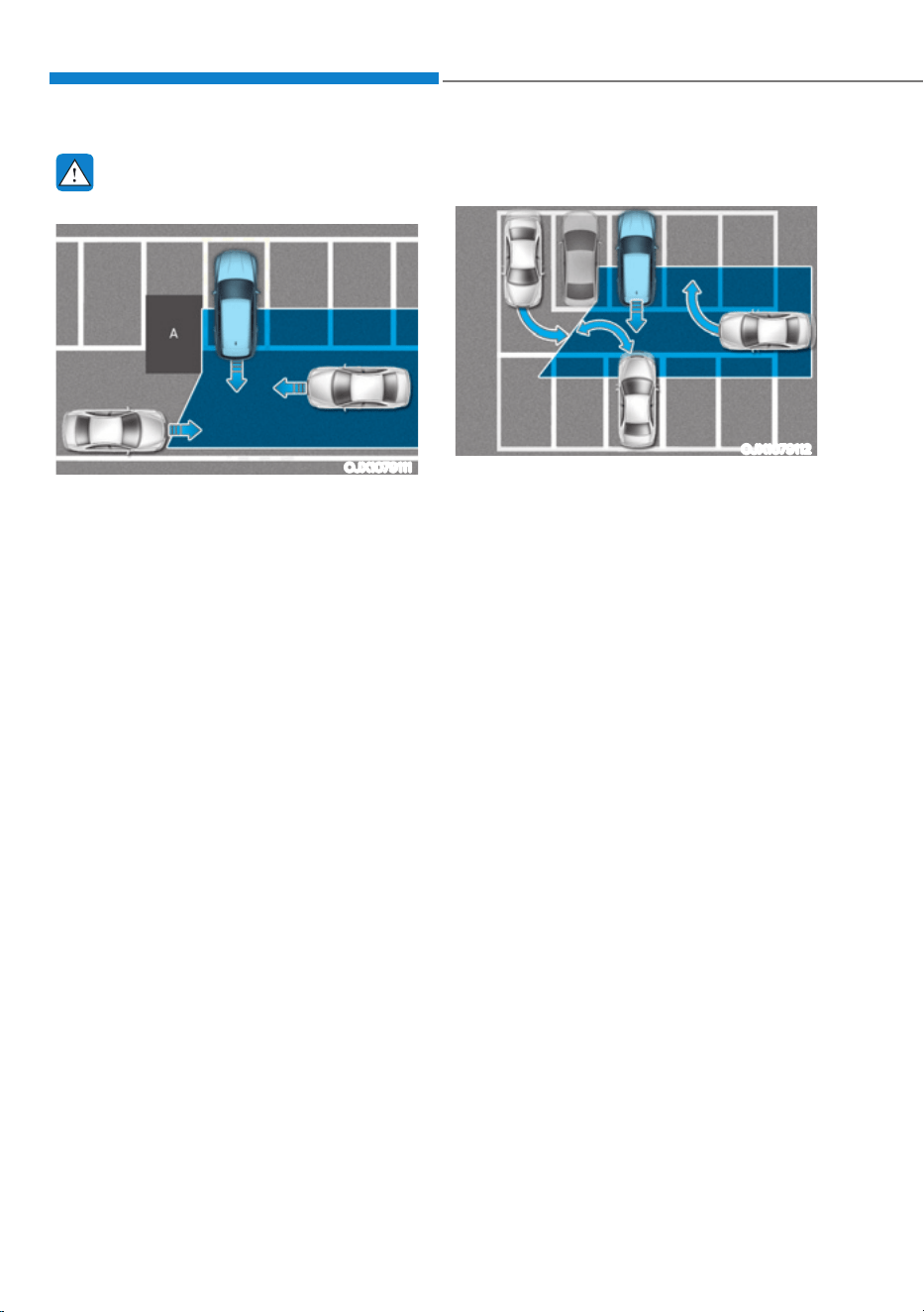
Driver Assistance System
7-130
WARNING
ś Driving near a vehicle or structure
OJX1079111
[A] : Structure
Rear Cross-Traffic Collision-
Avoidance Assist may be limited
when driving near a vehicle or
structure, and may not detect the
vehicle approaching from the left or
right. If this occurs, the function may
not warn the driver or control the
brakes when necessary.
Always check your surroundings
while backing up.
ś When the vehicle is in a complex
parking environment
OJX1079112
Rear Cross-Traffic Collision-
Avoidance Assist may detect vehicles
which are parking or pulling out
near your vehicle (for example, a
vehicle leaving beside your vehicle,
a vehicle parking or pulling out in
the rear area, a vehicle approaching
your vehicle making a turn, etc.).
If this occurs, the function may
unnecessarily warn the driver and
control the brake.
Always check your surroundings
while backing up.
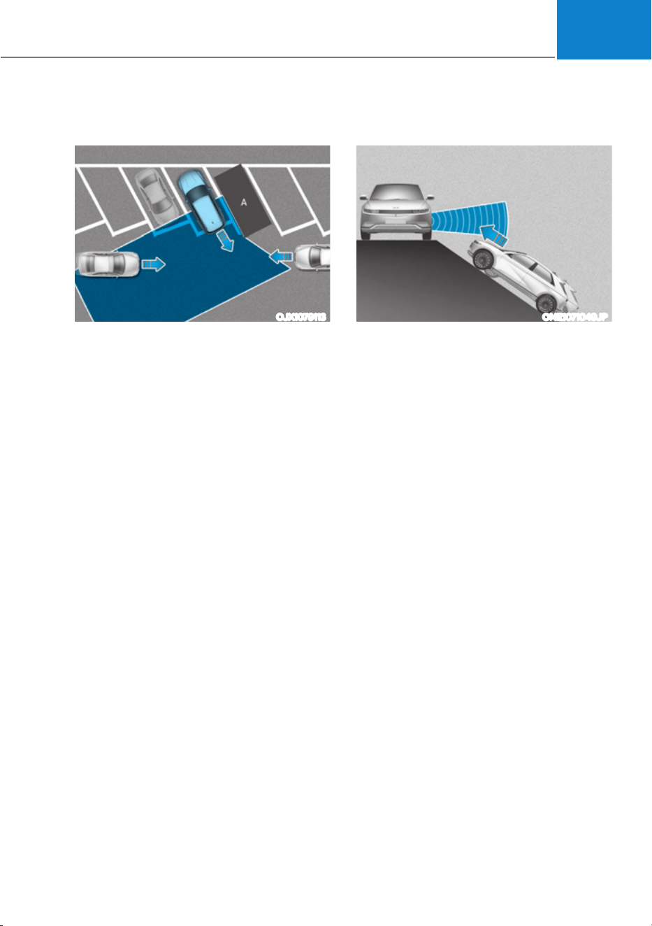
07
7-131
ś When the vehicle is parked
diagonally
OJX1079113
[A] : Vehicle
Rear Cross-Traffic Collision-
Avoidance Assist may be limited
when backing up diagonally,
and may not detect the vehicle
approaching from the left or right.
If this occurs, the function may not
warn the driver or control the brakes
when necessary.
Always check your surroundings
while backing up.
ś When the vehicle is on or near a
slope
ONE1071049JP
Rear Cross-Traffic Collision-
Avoidance Assist may be limited
when the vehicle is on a uphill or
downhill slope, or near it, and may
not detect the vehicle approaching
from the left or right. If this occurs,
the function may not warn the
driver or control the brakes when
necessary.
Always check your surroundings
while backing up.
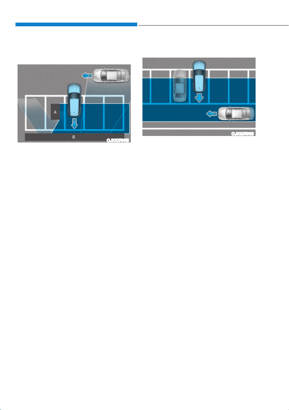
Driver Assistance System
7-132
ś Pulling into the parking space where
there is a structure
OJX1079115
[A] : Structure, [B] : Wall
Rear Cross-Traffic Collision-
Avoidance Assist may detect vehicles
passing by in front of you when
parking in reverse into a parking
space with a wall or structure in the
rear or side area. If this occurs, the
function may unnecessarily warn the
driver and control the brake.
Always check your surroundings
while backing up.
ś When the vehicle is parked rearward
OJX1079116
Rear Cross-Traffic Collision-
Avoidance Assist may detect vehicles
passing by behind you when parking
in reverse into a parking space.
If this occurs, the function may
unnecessarily warn the driver and
control the brake.
Always check your surroundings
while backing up.

07
7-133
WARNING
ś When you are towing a trailer or
another vehicle, turn off Rear Cross-
Traffic Collision-Avoidance Assist for
safety reasons.
ś Rear Cross-Traffic Collision-
Avoidance Assist may not operate
properly if interfered by strong
electromagnetic waves.
ś Rear Cross-Traffic Collision-
Avoidance Assist may not operate
for 15 seconds after the vehicle is
started, or the rear corner radars are
initialized.
Information
This device complies with Part 15 of the
FCC rules.
Operation is subject to the following three
conditions:
1. This device may not cause harmful
interference, and
2. This device must accept any
interference received, including
interference that may cause undesired
operation of the device.
3. Changes or modifications not expressly
approved by the party responsible
for compliance could void the user's
authority to operate the device.
Information
Radio frequency radiation exposure
information:
This equipment complies with FCC
radiation exposure limits set forth for an
uncontrolled environment.
This equipment should be installed and
operated with minimum distance of 8 in.
(20 cm) between the radiator (antenna)
and your body.
This transmitter must not be co-located or
operating in conjunction with any other
antenna or transmitter.
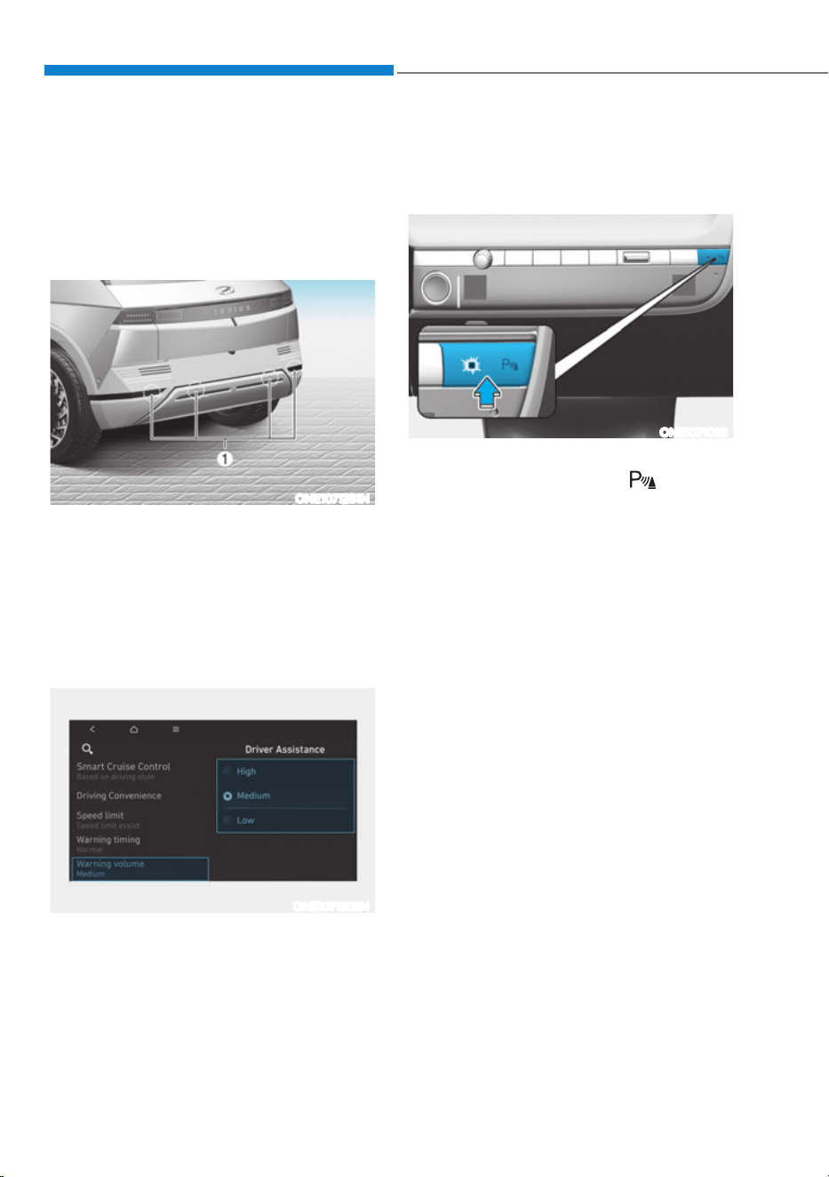
Driver Assistance System
7-134
Reverse Parking Distance Warning can
help warn the driver if an obstacle is
detected within a certain distance when
the vehicle is moving in reverse at low
speeds.
Detecting sensor
ONE1071281N
[1] : Rear ultrasonic sensors
Refer to the picture above for the
detailed location of the detecting
sensors.
Reverse Parking Distance
Warning Settings
Warning Volume
ONE1071202N
With the vehicle on, select ‘Driver
$VVLVWDQFHƟ:DUQLQJ9ROXPHŔIURPWKH
Settings menu to change the Warning
Volume to ‘High’, ‘Medium’ or ‘Low’ for
Reverse Parking Distance Warning.
If you change the warning volume,
the Warning Volume of other Driver
Assistance systems may change.
Reverse Parking Distance
Warning Operation
Operating button
ONE1071052
Parking Safety button (if equipped)
ś Press the Parking Safety ( ) button
to turn on Reverse Parking Distance
Warning. Press the button again to
turn off the function.
ś When Reverse Parking Distance
Warning is off (button indicator
light off), if you shift the gear to R
(Reverse), Reverse Parking Distance
Warning will automatically turn on.
5(9(56(3$5.,1*',67$1&(:$51,1*ǣ3':Ǥǣ,)(48,33('Ǥ
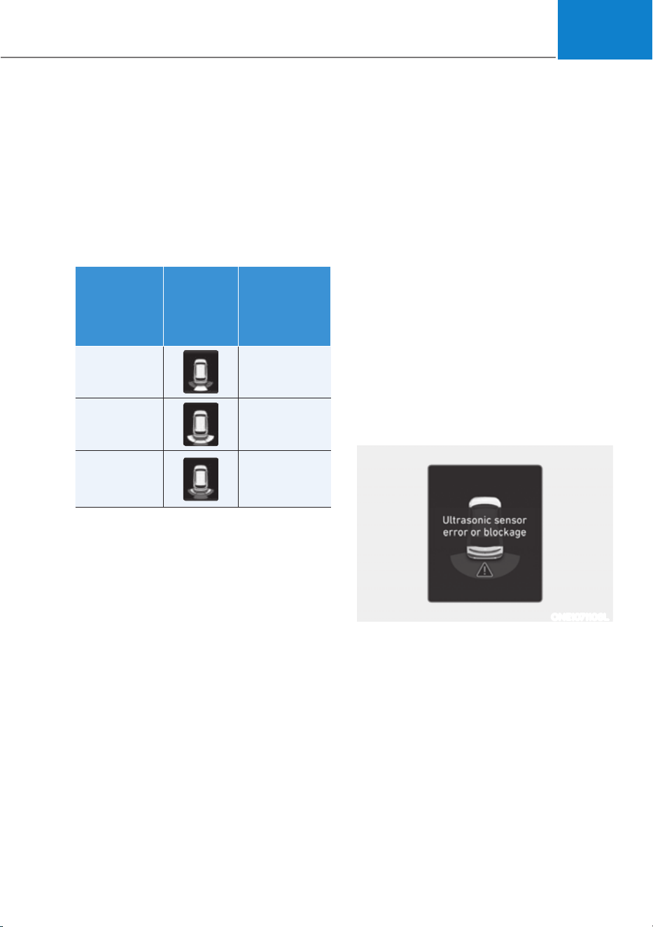
07
7-135
Reverse Parking Distance Warning
ś Reverse Parking Distance Warning
will operate when the gear is in R
(Reverse).
ś Reverse Parking Distance Warning
helps detect a person, animal or
object in the rear when the vehicle’s
rearward speed is below 6 mph (10
km/h).
Distance
from object
Warning
indicator
when
driving
backward
Warning
sound
24 - 48 in.
(60 - 120 cm)
Buzzer beeps
intermittently
12 - 24 in. (30
- 60 cm)
Beeps more
frequently
12 in.
(within 30
cm)
Beeps
continuously
ś The corresponding indicator will
illuminate whenever each ultrasonic
sensor detects a person, animal or
object in its sensing range. Also an
audible warning will sound.
ś When more than two objects are
detected at the same time, the closest
one will be warned with an audible
warning.
ś The shape of the indicator in the
illustration may differ from the actual
vehicle.
Reverse Parking Distance
Warning Malfunction and
Precautions
Reverse Parking Distance Warning
malfunction
After starting the vehicle, a beep will
sound when the gear is shifted to R
(Reverse) to indicate Reverse Parking
Distance Warning is operating properly.
However, if one or more of the following
occurs, first check whether the ultrasonic
sensor is damaged or blocked with
foreign material. If it still does not work
properly, have the vehicle be inspected
by an authorized HYUNDAI dealer.
ś The audible warning does not sound.
ś The buzzer sounds intermittently.
ś The ‘Ultrasonic sensor error or
blockage’ warning message appears
on the cluster.
ONE1071106L

Driver Assistance System
7-136
WARNING
ś Reverse Parking Distance Warning
is a supplemental function. The
operation of Reverse Parking
Distance Warning can be affected
by several factors (including
environmental conditions). It is the
responsibility of the driver to always
check the rear view before and while
parking.
ś Your new vehicle warranty does not
cover any accidents or damage to
the vehicle due to the malfunction of
Reverse Parking Distance Warning.
ś Pay close attention when driving
near objects, pedestrians, and
especially children. Some objects
may not be detected by the
ultrasonic sensors, due to the objects
distance, size or material, all of
which can limit the effectiveness of
the sensor.
Limitations of Reverse Parking
Distance Warning
ś Reverse Parking Distance Warning
may not operate properly when:
- Moisture is frozen to the sensor
- Sensor is covered with foreign
material, such as snow or water
(Reverse Parking Distance Warning
will operate properly when such
foreign material are removed.)
- The weather is extremely hot or cold
The sensor or sensor assembly is
disassembled
- The surface of the sensor is pressed
hard or hit with a hard object
- The surface of the sensor is
scratched with a sharp object
- The sensors or its surrounding
area is directly sprayed with high
pressure washer
ś Reverse Parking Distance Warning
may malfunction when:
- Heavy rain or water spray is present
- Water flows on the surface of the
sensor
- Affected by another vehicle’s
sensors
- The sensor is covered with snow
- Driving on uneven road, gravel
roads or bushes
- Objects that generates ultrasonic
waves are near the sensor
- License plate is installed in a
different spot from the original
location
- The vehicle bumper height or
ultrasonic sensor installation has
been modified
- Attaching equipment or accessories
next to the ultrasonic sensors
ś The following objects may not be
detected:
- Sharp or slim objects, such as ropes,
chains or small poles.
- Objects, which tend to absorb
sensor frequency, such as clothes,
spongy material or snow.
- Objects smaller than 40 in. (100 cm)
in length and narrower than 6 in. (14
cm) in diameter.
- Pedestrians, animals or objects
that are very close to the ultrasonic
sensors
ś Parking Distance Warning Indicators
may be displayed differently from
the actual detected location when
the obstacle is located between the
sensors.
ś Parking Distance Warning indicator
may not occur sequentially depending
on vehicle speed or obstacle shape.
ś If Reverse Parking Distance Warning
needs repair, have the vehicle be
inspected by an authorized HYUNDAI
dealer.
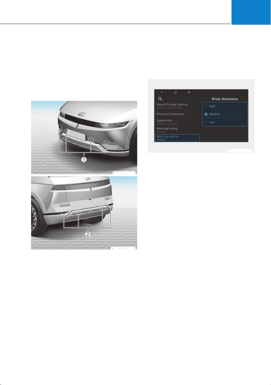
07
7-137
Forward/Reverse Parking Distance
Warning will help warn the driver if an
obstacle is detected within a certain
distance when the vehicle is moving
forward or in reverse at low speeds.
Detecting sensor
ONE1071050
ONE1071051N
[1] : Front ultrasonic sensors,
[2] : Rear ultrasonic sensors
Refer to the picture above for the
detailed location of the detecting
sensors.
Forward/Reverse Parking
Distance Warning Settings
Warning Volume
ONE1071202N
With the vehicle on, select ‘Driver
$VVLVWDQFHƟ:DUQLQJ9ROXPHŔIURPWKH
Settings menu to change the Warning
Volume to ‘High’, ‘Medium’ or ‘Low’
for Forward/Reverse Parking Distance
Warning.
If you change the Warning Volume,
the warning volume of other Driver
Assistance systems may change.
Parking Distance Warning Auto On
To use Parking Distance Warning Auto
On function, select ‘Driver Assistance
Ɵ3DUNLQJ6DIHW\Ɵ3DUNLQJ'LVWDQFH
Warning Auto On’ from the cluster or
infotainment system Settings menu.
)25:$5'5(9(56(3$5.,1*',67$1&(:$51,1*ǣ3':Ǥ
ǣ,)(48,33('Ǥ
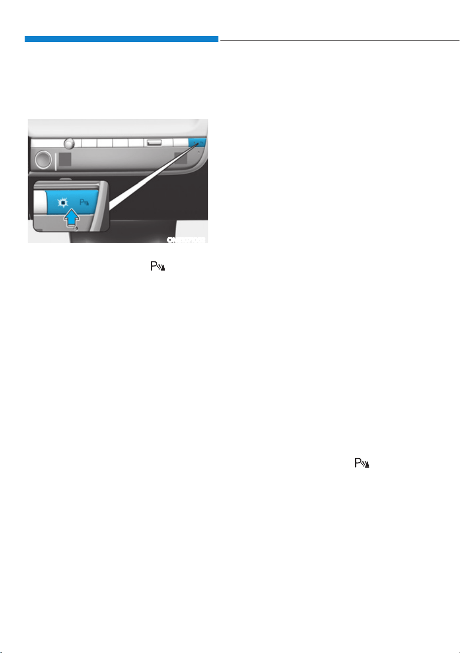
Driver Assistance System
7-138
Forward/Reverse Parking
Distance Warning Operation
Operating button
ONE1071052
Parking Safety button
ś Press the Parking Safety ( ) button
to turn on Forward/Reverse Parking
Distance Warning. Press the button
again to turn off the function.
ś When Forward/Reverse Parking
Distance Warning is off (button
indicator light off), if you shift the
gear to R (Reverse), Forward/Reverse
Parking Distance Warning will
automatically turn on.
ś When Forward/Reverse Parking
Distance Warning turns on, the button
indicator light will turn on. If vehicle
speed is above 12 mph (20 km/h),
Forward/Reverse Parking Distance
Warning will turn off (button indicator
light off).
à If equipped with Reverse Parking
Collision-Avoidance Assist or
Remote Smart Parking Assist,
Forward/Reverse Parking Distance
Warning will turn off (button
indicator light off) when vehicle
speed is above 18 mph (30 km/h).
Forward Parking Distance Warning
ś Forward Parking Distance Warning will
operate when one of the condition is
satisfied.
- The gear is shifted from R (Reverse)
to D (Drive) with Reverse Parking
Distance Warning on
- The gear is in D (Drive) and the
Parking Safety button indicator light
is on
- ‘Parking Distance Warning Auto On’
is selected from the Settings menu
and the gear is in D (Drive)
ś Forward Parking Distance Warning
helps detect a person, animal or
object in front when the vehicle’s
forward speed is below 6 mph (10
km/h).
ś Forward Parking Distance Warning
does not operate when the vehicle's
forward speed is above 6 mph (10
km/h) even when the Parking Safety
button indicator is on. Forward
Parking Distance Warning will operate
again when the vehicle's forward
speed decreases below 6 mph (10
km/h) while the Parking Safety button
indicator is on.
ś When ‘Parking Distance Warning Auto
On’ is selected, the Parking Safety
button indicator light stays on.
ś When ‘Parking Distance Warning Auto
On’ is deselected, and the vehicle’s
forward speed is above 12 mph (20
km/h), the Parking Safety (
) button
indicator will turn off. Although you
drive below 6 mph (10 km/h), Forward
Parking Distance Warning will not turn
on.
à If equipped with Reverse Parking
Collision-Avoidance Assist or
Remote Smart Parking Assist,
Forward/Reverse Parking Distance
Warning will turn off when vehicle
speed is above 18 mph (30 km/h).
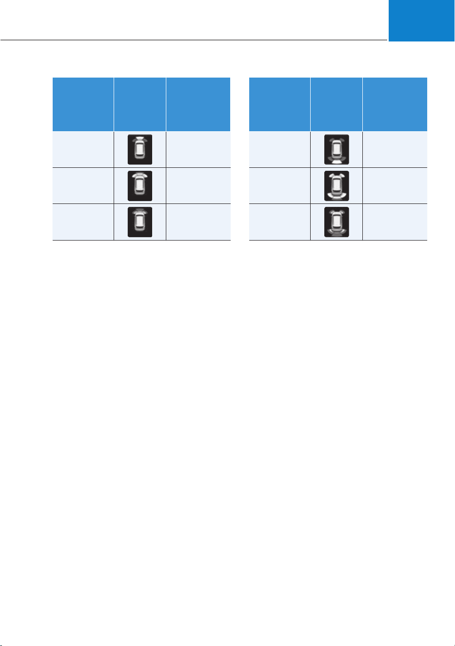
07
7-139
Distance
from object
Warning
indicator
when
driving
forward
Warning
sound
24 - 40 in.
(60 - 100 cm)
Buzzer beeps
intermittently
12 - 24 in.
(30 - 60 cm)
Beeps more
frequently
12 in.
(within 30
cm)
Beeps
continuously
ś The corresponding indicator will
illuminate whenever each ultrasonic
sensor detects a person, animal or
object in its sensing range. Also an
audible warning will sound.
ś When more than two objects are
detected at the same time, the closest
one will be warned with an audible
warning.
ś The shape of the indicator in the
illustration may differ from the actual
vehicle.
Reverse Parking Distance Warning
ś Reverse Parking Distance Warning
will operate when the gear is in R
(Reverse).
ś Reverse Parking Distance Warning
helps detect a person, animal or
object in the rear when the vehicle’s
rearward speed is below 6 mph (10
km/h).
ś When the vehicle’s rearward speed is
below 6 mph (10 km/h), both the front
and rear ultrasonic sensors will help
detect objects. However, the front
ultrasonic sensors can help detect a
person, animal or object when it is
within 24 in. (60 cm) from the sensors.
Distance
from object
Warning
indicator
when
driving
backward
Warning
sound
24 - 48 in.
(60 - 120 cm)
Buzzer beeps
intermittently
12 - 24 in.
(30 - 60 cm)
Beeps more
frequently
12 in.
(within 30
cm)
Beeps
continuously
ś The corresponding indicator will
illuminate whenever each ultrasonic
sensor detects a person, animal or
object in its sensing range. Also an
audible warning will sound.
ś When more than two objects are
detected at the same time, the closest
one will be warned with an audible
warning.
ś The shape of the indicator in the
illustration may differ from the actual
vehicle.
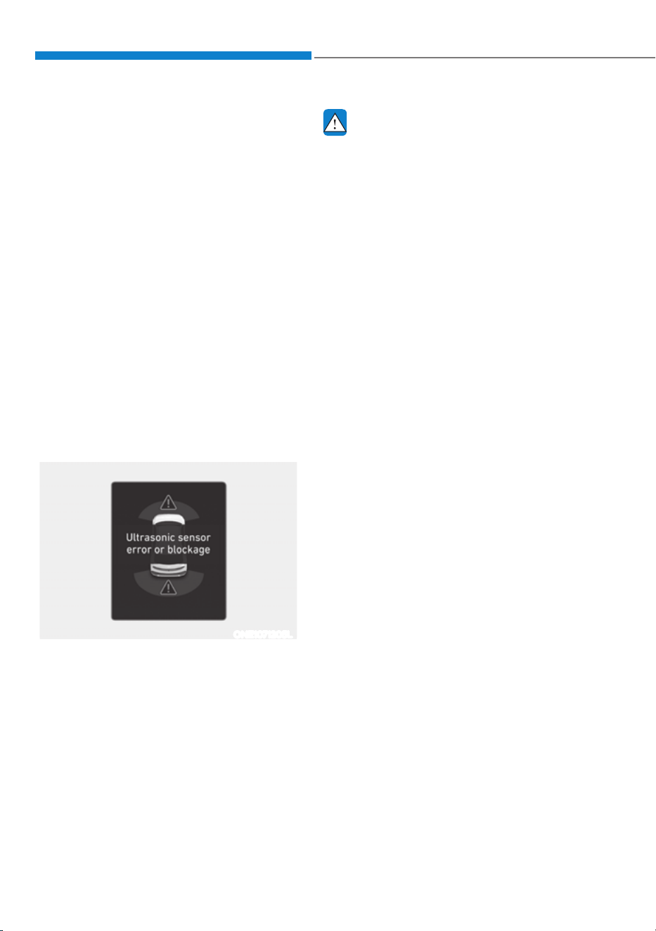
Driver Assistance System
7-140
Forward/Reverse Parking
Distance Warning Malfunction
and Precautions
Forward/Reverse Parking Distance
Warning malfunction
After starting the vehicle, a beep will
sound when the gear is shifted to R
(Reverse) to indicate Forward/Reverse
Parking Distance Warning is operating
properly.
However, if one or more of the following
occurs, first check whether the ultrasonic
sensor is damaged or blocked with
foreign material. If it still does not work
properly, have the vehicle be inspected
by an authorized HYUNDAI dealer.
ś The audible warning does not sound.
ś The buzzer sounds intermittently.
ś The ‘Ultrasonic sensor error or
blockage’ warning message appears
on the cluster.
ONE1071205L
WARNING
ś Forward/Reverse Parking Distance
Warning is a supplemental function.
The operation of Forward/Reverse
Parking Distance Warning can be
affected by several factors (including
environmental conditions). It is the
responsibility of the driver to always
check the front and rear views before
and while parking.
ś Your new vehicle warranty does not
cover any accidents or damage to
the vehicle due to the malfunction of
Forward/Reverse Parking Distance
Warning.
ś Pay close attention when driving
near objects, pedestrians, and
especially children. Some objects
may not be detected by the
ultrasonic sensors, due to the objects
distance, size or material, all of
which can limit the effectiveness of
the sensor.

07
7-141
Limitations of Forward/Reverse
Parking Distance Warning
ś Forward/Reverse Parking Distance
Warning may not operate properly
when:
- Moisture is frozen to the sensor
- Sensor is covered with substance,
such as snow or water (Forward/
Reverse Parking Distance Warning
will operate properly when such
substance is removed.)
- The weather is extremely hot or cold
- The sensor or sensor assembly is
disassembled
- The surface of the sensor is pressed
hard or hit with a hard object
- The surface of the sensor is
scratched with a sharp object
- The sensors or its surrounding
area is directly sprayed with high
pressure washer
ś Forward/Reverse Parking Distance
Warning may malfunction when:
- Heavy rain or water spray is present
- Water flows on the surface of the
sensor
- Affected by another vehicle’s
sensors
- The sensor is covered with snow or
ice
- Driving on uneven road, gravel
roads or bushes
- Objects that generates ultrasonic
waves are near the sensor
- License plate is installed in a
different spot from the original
location
- The vehicle bumper height or
ultrasonic sensor installation has
been modified
- Attaching equipment or accessories
next to the ultrasonic sensors
ś The following objects may not be
detected:
- Sharp or slim objects, such as ropes,
chains or small poles.
- Objects, which tend to absorb
sensor frequency, such as clothes,
spongy material or snow.
- Objects smaller than 40 in. (100 cm)
in length and narrower than 6 in. (14
cm) in diameter.
- Pedestrians, animals or objects
that are very close to the ultrasonic
sensors
ś Parking Distance Warning Indicators
may be displayed differently from
the actual detected location when
the obstacle is located between the
sensors.
ś Parking Distance Warning indicator
may not occur sequentially depending
on vehicle speed or obstacle shape.
ś If Forward/Reverse Parking Distance
Warning needs repair, have the
vehicle be inspected by an authorized
HYUNDAI dealer.
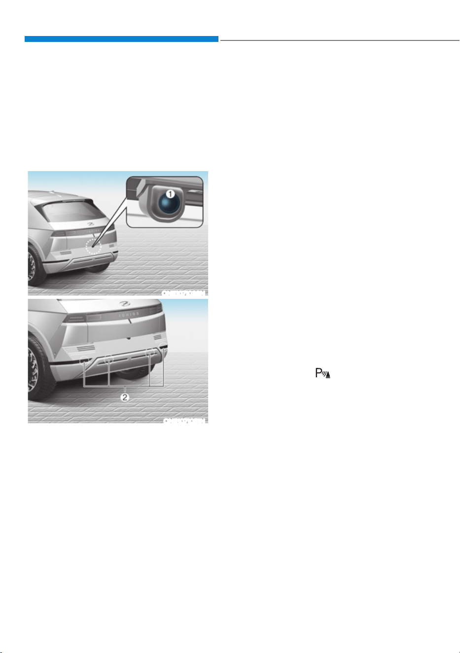
Driver Assistance System
7-142
Reverse Parking Collision-Avoidance
Assist can warn the driver or assist with
braking to help reduce the possibility of
collision with a pedestrian or an object
when backing up.
Detecting sensor
ONE1071038N
ONE1071051N
[1] : Rear view camera,
[2] : Rear ultrasonic sensors
Refer to the picture above for the
detailed location of the detecting
sensors.
Reverse Parking Collision-
Avoidance Assist Settings
Setting features
Parking Safety
ś With the vehicle on, select or deselect
œ'ULYHU$VVLVWDQFHƟ3DUNLQJ6DIHW\Ŕ
from the Settings menu to set
whether or not to use each function.
- If ‘Rear Active Assist’ (or ‘Active rear
assist’) is selected, Reverse Parking
Collision-Avoidance Assist will warn
the driver and assist with braking
when a collision with a pedestrian
or an object is imminent.
- If ‘Rear Warning Only’ (or ‘Rear
warning only’) is selected, Reverse
Parking Collision-Avoidance Assist
will warn the driver when a collision
with a pedestrian or an object
is imminent. Braking will not be
assisted.
- If ‘Off’ is selected, Reverse Parking
Collision-Avoidance Assist will turn
off.
ś If Parking Safety (
) button is
pressed more than 2 seconds, ‘Rear
Active Assist’ or ‘Rear Warning Only’
can be turned on or off.
- Whenever the vehicle is restarted,
‘Rear Active Assist’ is automatically
selected.
5(9(56(3$5.,1*&2//,6,21ǘ$92,'$1&($66,67ǣ3&$Ǥǣ,)
(48,33('Ǥ

07
7-143
ONE1071282N
Warning Timing
With the vehicle on, select ‘Driver
$VVLVWDQFHƟ:DUQLQJ7LPLQJŔIURPWKH
Settings menu to change the initial
warning activation time for Reverse
Parking Collision-Avoidance Assist.
If you change the Warning Timing,
the Warning Timing of other Driver
Assistance systems may change.
ONE1071202N
Warning Volume
With the vehicle on, select ‘Driver
$VVLVWDQFHƟ:DUQLQJ9ROXPHŔIURPWKH
Settings menu to change the Warning
Volume to ‘High’, ‘Medium’ or ‘Low’ for
Reverse Parking Collision-Avoidance
Assist.
If you change the warning volume,
the Warning Volume of other Driver
Assistance systems may change.

Driver Assistance System
7-144
Reverse Parking Collision-
Avoidance Assist Operation
Operating conditions
If ‘Rear Active Assist’ or ‘Rear Warning
Only’ is set from the Settings menu,
Reverse Parking Collision-Avoidance
Assist will be in the ready status when
the following conditions are satisfied:
- The liftgate is closed
- The gear is shifted to R (Reverse)
- Vehicle speed is below 6 mph (10
km/h)
- Reverse Parking Collision-Avoidance
Assist components such as the rear
view camera and the rear ultrasonic
sensors are in normal conditions
When Reverse Parking Collision-
Avoidance Assist activates, a line
appears behind the vehicle image in the
instrument cluster.
Reverse Parking Collision-Avoidance
Assist operates only once after the gear
is shifted to R (Reverse). To reactivate
Reverse Parking Collision-Avoidance
Assist, shift the gear from another gear
to R (Reverse).
ONE1071053
Rear Active Assist
ś If Reverse Parking Collision-Avoidance
Assist detects a risk of collision with
a pedestrian or an object, Reverse
Parking Collision-Avoidance Assist
will warn the driver with an audible
warning and warning message on the
cluster. When Rear View Monitor is
operating, a warning will appear on
the infotainment system screen.
ś If Reverse Parking Collision-Avoidance
Assist detects an imminent collision
with a pedestrian or an object behind
the vehicle, Reverse Parking Collision-
Avoidance Assist will assist you with
braking. The driver needs to pay
attention as the brake assist will end
within 5 minutes. The driver must
immediately depress the brake pedal
and check vehicle surroundings.
ś Brake control will end when:
- The gear is shifted to P (Park) or D
(Drive).
- The driver depresses the brake
pedal with sufficient power
- Braking assist has last for
approximately 5 minutes, the
Electronic Parking Brake (EPB)
is engaged at the brake assist is
released
ś The warning will turn off when:
- The gear is shifted to P (Park), N
(Neutral), or D (Drive)
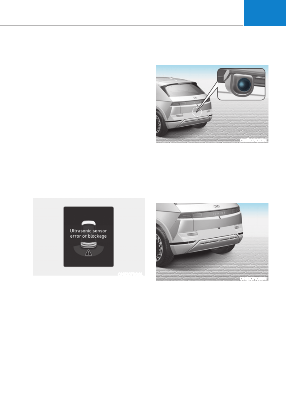
07
7-145
Rear Warning Only
ś If Reverse Parking Collision-Avoidance
Assist detects a risk of collision with
a pedestrian or an object, Reverse
Parking Collision-Avoidance Assist
will warn the driver with an audible
warning and warning message on the
cluster. When Rear View Monitor is
operating, a warning will appear on
the infotainment system screen.
ś If ‘Rear Warning Only’ is selected,
braking will not be assisted.
ś The warning will turn off when the
gear is shifted to P (Park), N (Neutral)
or D (Drive).
Reverse Parking Collision-
Avoidance Assist Malfunction
and Limitations
Reverse Parking Collision-
Avoidance Assist malfunction
ONE1071106L
When Reverse Parking Collision-
Avoidance Assist or other related
functions are not working properly, the
‘Check Parking Safety system’ warning
message will appear on the cluster, and
Reverse Parking Collision-Avoidance
Assist will turn off automatically.
Have the vehicle be inspected by an
authorized HYUNDAI dealer.
Reverse Parking Collision-Avoidance
Assist disabled
ONE1071037N
The rear view camera is used as a
detecting sensor to detect pedestrians. If
the camera lens is covered with foreign
material, such as snow or rain, it may
adversely affect camera performance
and Reverse Parking Collision-Avoidance
Assist may not operate properly. Always
keep the camera lens clean.
ONE1071055N
The rear ultrasonic sensors are located
inside the rear bumper to detect objects
in the rear area. If the sensors are
covered with foreign material, such as
snow or rain, it may adversely affect
sensor performance and Reverse Parking
Collision-Avoidance Assist may not
operate properly. Always keep the rear
bumper clean.

Driver Assistance System
7-146
Rear view camera Rear ultrasonic
sensor
ONE1071056L ONE1071106L
The ‘Camera error or blockage’ or
‘Ultrasonic sensor error or blockage’
warning message will appear on the
cluster if the following situations occur:
- The rear view camera or rear
ultrasonic sensor(s) is covered with
foreign material, such as snow or rain,
etc.
- There is inclement weather, such as
heavy snow, heavy rain, etc.
If this occurs, Reverse Parking Collision-
Avoidance Assist may turn off or may not
operate properly. Check whether the rear
view camera and rear ultrasonic sensors
are clean.
Limitations of Reverse Parking
Collision-Avoidance Assist
Reverse Parking Collision-Avoidance
Assist may not assist braking or warn
the driver even if there are pedestrians
or objects under the following
circumstances:
ś Any non-factory equipment or
accessory is installed
ś Your vehicle is unstable due to an
accident or other causes
ś Bumper height or rear ultrasonic
sensor installation has been modified
ś Rear view camera or rear ultrasonic
sensor(s) is damaged
ś Rear view camera or the rear
ultrasonic sensor(s) is stained with
foreign material, such as snow, dirt,
etc.
ś Rear view camera is obscured by a
light source or by inclement weather,
such as heavy rain, fog, snow, etc.
ś The surrounding is very bright or very
dark
ś Outside temperature is very high or
very low
ś The wind is either strong (above
12 mph (20 km/h)) or blowing
perpendicular to the rear bumper
ś Objects generating excessive
noise, such as vehicle horns, loud
motorcycle engines or truck air
brakes, are near your vehicle
ś An ultrasonic sensor with similar
frequency is near your vehicle
ś There is ground height difference
between the vehicle and the
pedestrian
ś The image of the pedestrian in the
rear view camera is indistinguishable
from the background

07
7-147
ś The pedestrian is near the rear edge of
the vehicle
ś The pedestrian is not standing upright
ś The pedestrian is either very short or
very tall for Reverse Parking Collision-
Avoidance Assist to detect
ś The pedestrian or cyclist is wearing
clothing that easily blends into the
background, making it difficult to
detect
ś The pedestrian is wearing clothing
that does not reflect ultrasonic waves
well
ś Size, thickness, height, or shape of
the object does not reflect ultrasonic
waves well (for example, pole, bush,
curbs, carts, edge of a wall, etc.)
ś The pedestrian or the object is moving
ś The pedestrian or the object is very
close to the rear of the vehicle
ś A wall is behind the pedestrian or the
object
ś The object is not located at the rear
center of your vehicle
ś The object is not parallel to the rear
bumper
ś The road is slippery or inclined
ś The driver backs up the vehicle
immediately after shifting to R
(Reverse)
ś The driver accelerates or circles the
vehicle
Reverse Parking Collision-Avoidance
Assist may unnecessarily warn the driver
or assist with braking even if there are
no pedestrians or objects under the
following circumstances:
ś Any non-factory equipment or
accessory is installed
ś Your vehicle is unstable due to an
accident or other causes
ś Bumper height or rear ultrasonic
sensor installation has been modified
ś Your vehicle height is low or high
due to heavy loads, abnormal tire
pressure, etc.
ś Rear view camera or the rear
ultrasonic sensor(s) is stained with
foreign material, such as snow, dirt,
etc.
ś The pattern on the road is mistaken
for a pedestrian
ś There is shadow or light reflecting on
the ground
ś Pedestrians or objects are around the
path of the vehicle
ś Objects generating excessive
noise, such as vehicle horns, loud
motorcycle engines or truck air
brakes, are near your vehicle
ś Your vehicle is backing towards a
narrow passage or parking space
ś Your vehicle is backing towards an
uneven road surface, such as an
unpaved road, gravel, bump, gradient,
etc.
ś A trailer or carrier is installed on the
rear of your vehicle
ś An ultrasonic sensor with similar
frequency is near your vehicle

Driver Assistance System
7-148
WARNING
Take the following precautions when
using Reverse Parking Collision-
Avoidance Assist:
ś Always pay extreme caution while
driving. The driver is responsible for
controlling the brake for safe driving.
ś Always pay attention to road and
traffic conditions while driving,
whether or not there is a warning.
ś Always look around your vehicle to
make sure there are no pedestrians
or objects before moving the vehicle.
ś The performance of Reverse Parking
Collision-Avoidance Assist may
vary under certain conditions. If
vehicle speed is above 2 mph (4
km/h), Reverse Parking Collision-
Avoidance Assist will provide
collision avoidance assist only when
pedestrians are detected. Always
look around and pay attention when
backing up your vehicle.
ś Some objects may not be detected
by the rear ultrasonic sensors due
to the objects distance, size or
material, all of which can limit the
effectiveness of the sensor.
ś Reverse Parking Collision-Avoidance
Assist may not operate properly
or may operate unnecessarily
depending on the road conditions
and the surroundings.
ś Do not solely rely on Reverse Parking
Collision-Avoidance Assist. Doing
so may lead to vehicle damage or
injuries.
CAUTION
ś Noise may be heard when sudden
braking occurs to avoid a collision.
ś If any other warning sound such
as the seat belt warning chime is
already generated, Reverse Parking
Collision-Avoidance Assist warning
may not sound.
ś Reverse Parking Collision-Avoidance
Assist may not work properly if the
bumper has been damaged, replaced
or repaired.
ś Reverse Parking Collision-Avoidance
Assist may not operate properly if
interfered by strong electromagnetic
waves.
ś Playing the vehicle audio system at
high volume may prevent passengers
from hearing Reverse Parking
Collision-Avoidance Assist warning
sounds.
ś Turn off Reverse Parking Collision-
Avoidance Assist when towing a
trailer. If towing and moving in
reverse, Reverse Parking Collision-
Avoidance Assist will activate as it
detects the trailer.
ś The brake control may not operate
properly depending on the status of
ESC (Electronic Stability Control).
There will only be a warning when:
- The ESC (Electronic Stability
Control) warning light is on
- ESC (Electronic Stability Control) is
engaged in a different function

07
7-149
CAUTION
Take the following precautions to
maintain optimal performance of the
detecting sensors:
ś Always keep the rear view camera
and rear ultrasonic sensors clean.
ś Do not use any cleanser containing
acid or alkaline detergents when
cleaning the rear view camera lens.
Use only a mild soap or neutral
detergent, and rinse thoroughly with
water.
ś Do not spray the rear view camera or
the rear ultrasonic sensors or their
surrounding area directly with a
high pressure washer. It may cause
the rear view camera or the rear
ultrasonic sensors to malfunction.
ś Do not apply objects, such as a
bumper sticker or a bumper guard,
near the rear view camera or rear
ultrasonic sensors or apply paint to
the bumper. Doing so may adversely
affect the performance of Reverse
Parking Collision-Avoidance Assist.
ś Never disassemble or apply impact
on the rear view camera or the rear
ultrasonic sensors components.
ś Do not apply unnecessary force on
the rear view camera or the rear
ultrasonic sensors. Reverse Parking
Collision-Avoidance Assist may
not operate properly if the rear
view camera or the rear ultrasonic
sensor(s) is forcibly moved out of
proper alignment. Have the vehicle
be inspected by an authorized
HYUNDAI dealer.
Information
Reverse Parking Collision-Avoidance
Assist can detect a pedestrian or an object
when:
ś A pedestrian is standing behind the
vehicle
ś A large obstacle, such as a vehicle,
is parked in the rear center of your
vehicle
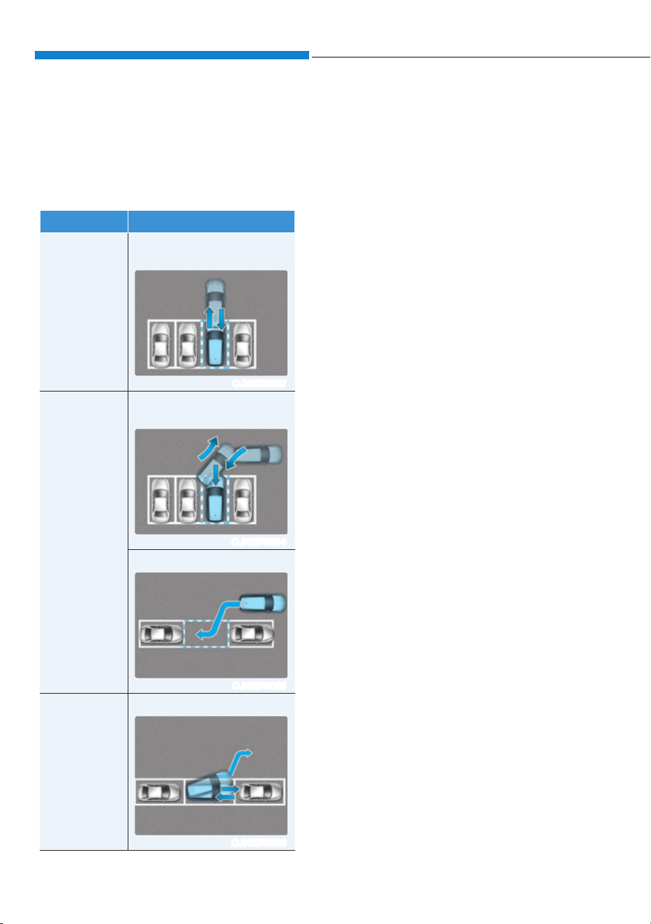
Driver Assistance System
7-150
Remote Smart Parking Assist uses
vehicle sensors to help the driver park
and exit parking spaces remotely from
outside the vehicle by controlling the
steering wheel, vehicle speed and
gearshifts.
Function Description
Remote
Operation
Remotely moving forward
or backward
OJX1079037
Smart
Parking or
Remote
Smart
Parking
Perpendicular reverse
parking
OJX1079034
Parallel reverse parking
OJX1079035
Smart Exit
Parallel forward exit
OJX1079036
ś Remote Smart Parking and Remote
Operation function may be operated
from outside the vehicle using the
smart key.
ś Smart Parking and Remote Smart
Parking function may be operated
from inside the vehicle.
ś Smart Parking and Remote Smart
Parking function helps the driver with
perpendicular reverse parking and
parallel reverse parking.
ś Smart Exit function helps the driver
with parallel forward exit.
ś When Remote Smart Parking Assist
operates, Parking Distance Warning,
Rear View monitor and Surround View
Monitor will also operate. For more
details, refer to “Parking Distance
Warning (PDW)”, “Rear View Monitor
(RVM)” and “Surround View Monitor
(SVM)” sections in this chapter.
5(027(60$573$5.,1*$66,67ǣ563$Ǥǣ,)(48,33('Ǥ
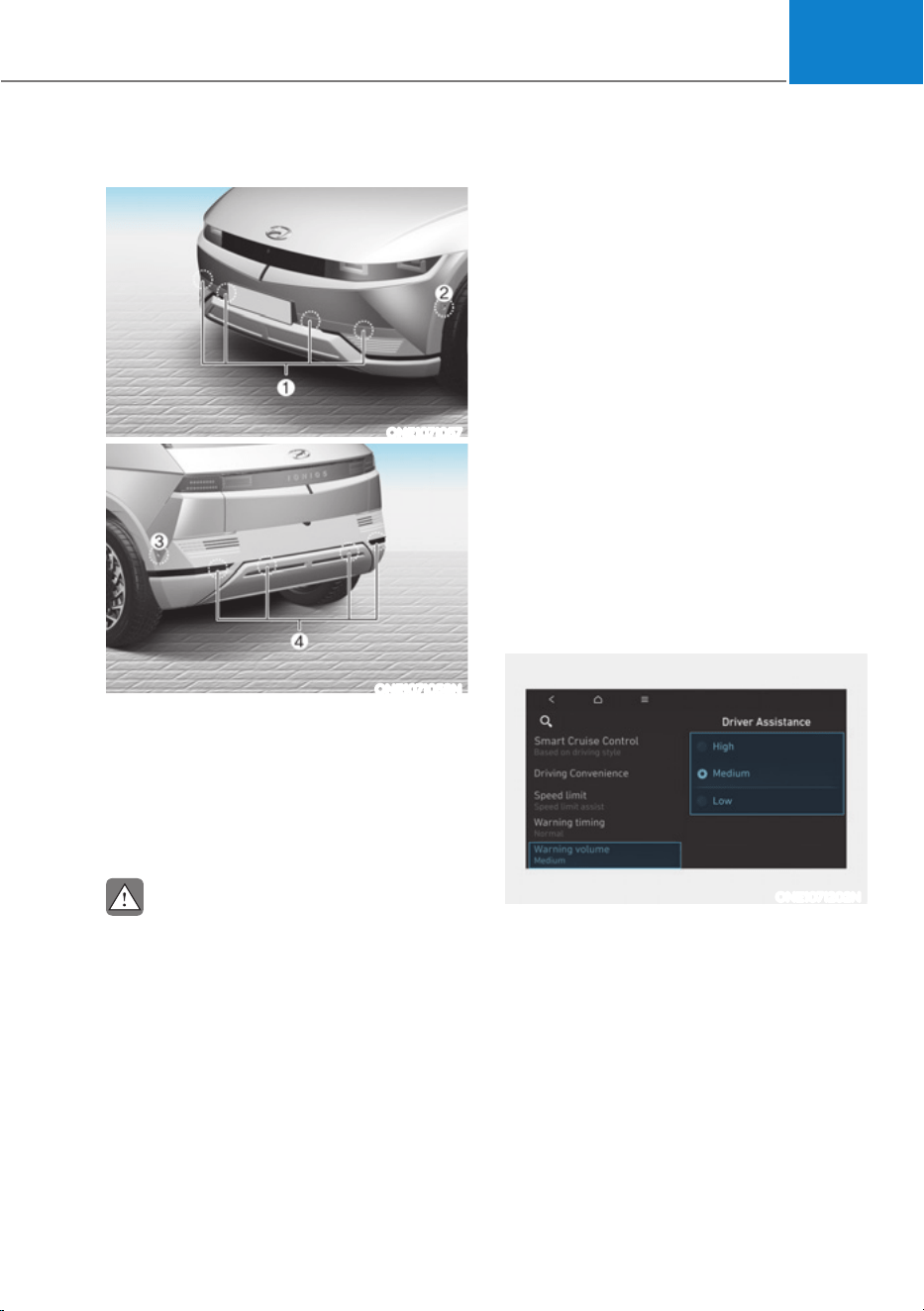
07
7-151
Detecting sensors
ONE1071057
ONE1071058N
[1] : Front ultrasonic sensors,
[2] : Front corner ultrasonic sensors,
[3] : Rear corner ultrasonic sensors,
[4] : Rear ultrasonic sensors
Refer to the picture above for the
detailed location of the detecting
sensors.
CAUTION
Take the following precautions to
maintain optimal performance of the
detecting sensors:
ś Never disassemble the detecting
sensor or sensor assembly, or cause
any damage to it.
ś If the detecting sensors need repair,
have the vehicle be inspected by an
authorized HYUNDAI dealer.
ś Remote Smart Parking Assist
may malfunction if the vehicle
bumper height or ultrasonic sensor
installation has been modified
or damaged. Any non-factory
installed equipment or accessories
may also interfere with the sensor
performance.
ś When the ultrasonic sensor is frozen
or stained with snow, dirt, or water,
the sensor may not operate until the
stains are removed using a soft cloth.
ś Do not push, scratch or strike the
ultrasonic sensor. Sensor damage
could occur.
ś Do not spray the ultrasonic sensors
or its surrounding area directly with
a high pressure washer.
Remote Smart Parking Assist
Settings
Settings features
ONE1071202N
Warning Volume
With the vehicle on, select ‘Driver
$VVLVWDQFHƟ:DUQLQJ9ROXPHŔIURPWKH
Settings menu to change the Warning
Volume to ‘High’, ‘Medium’ or ‘Low’ for
Remote Smart Parking Assist.
If you change the warning volume,
the Warning Volume of other Driver
Assistance systems may change.
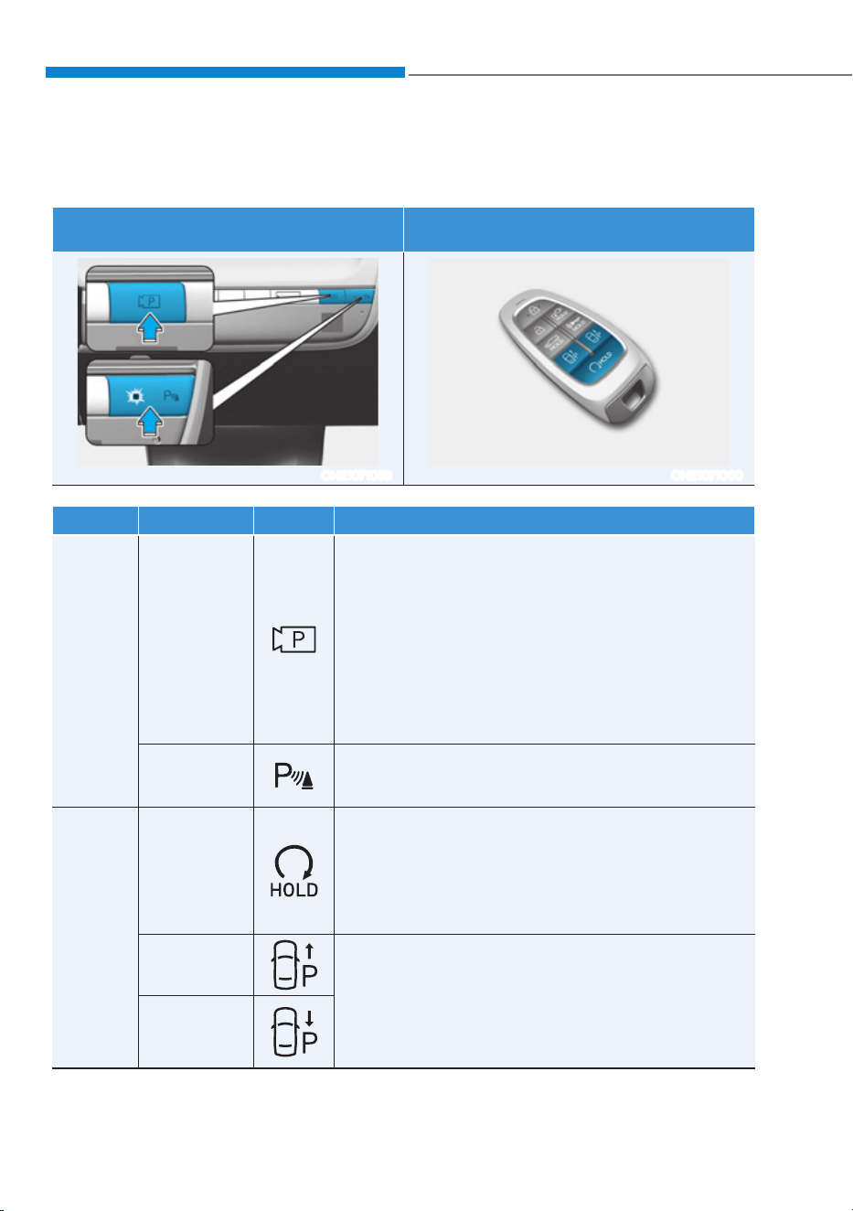
Driver Assistance System
7-152
Remote Smart Parking Assist Operation
Remote Smart Parking Assist button
Parking/View button, Parking Safety
button
Smart key
ONE1071059 ONE1071060
Location Name Symbol Description
Inside
vehicle
Parking/View
button
śPress and hold the Parking/View button to turn
on Remote Smart Parking Assist. Also, Forward/
Reverse Parking Distance warning will automatically
turn on.
However, functions may differ depending on the
situations. Refer to each function's description for
more details in the following pages.
śPress and hold the Parking/View button while Smart
Parking or Smart Exit function is on to operate the
function.
Parking
Safety button
śPress the Parking Safety button while Remote Smart
Parking Assist is operating to end Remote Smart
Parking Assist operation.
Smart
key
Remote Start
button
śPress the Remote Start button after the door is
locked with the vehicle off to start the vehicle
remotely.
śPress the Remote Start button while Remote Smart
Parking or Remote Operation function is operating
to end function operation.
Forward
button
śWhen using Remote Smart Parking function,
regardless of which direction button is pressed,
parking is supported while the button is pressed.
śWhen using the Remote Operation function, the
vehicle moves in the direction of the button while
the button is pressed.
Backward
button
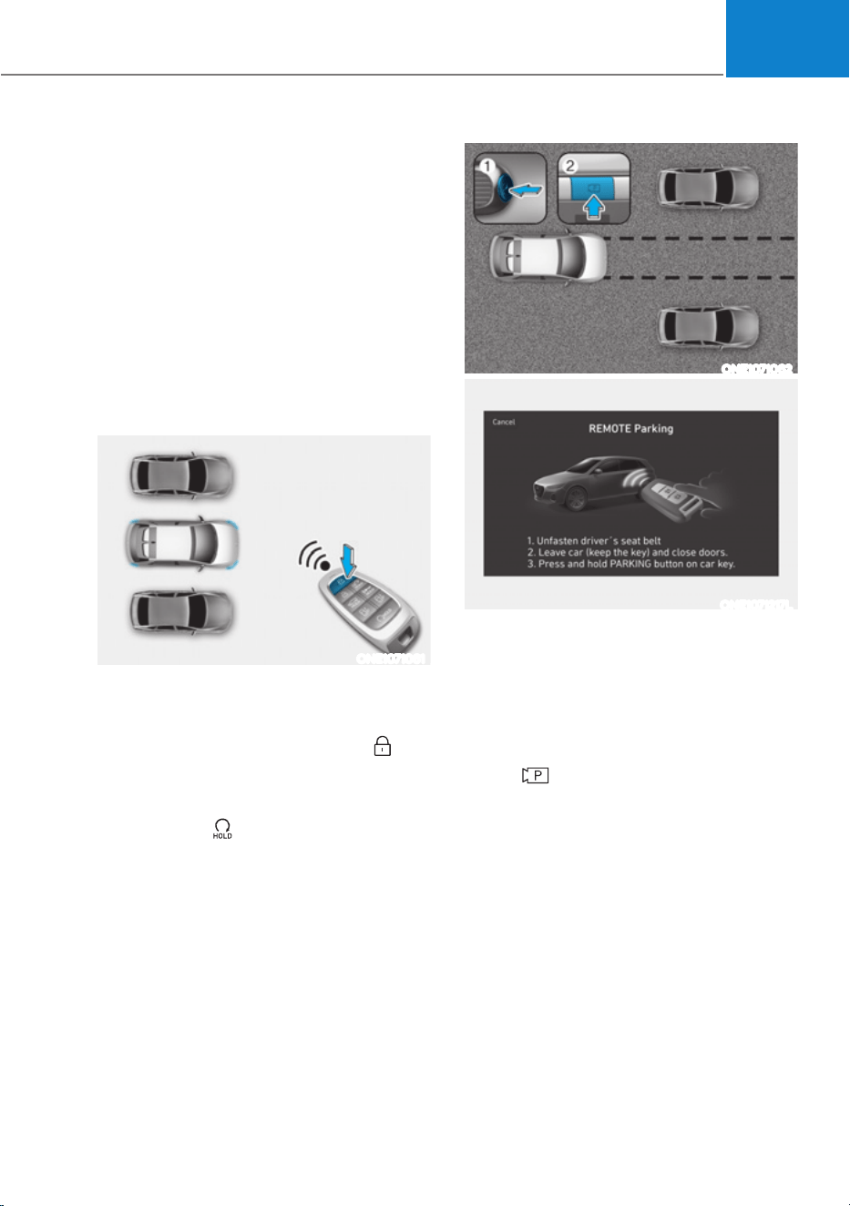
07
7-153
Remote Operation
Operating order
Remote Operation operates in the
following order:
1. Getting ready to remotely move
forward and backward
2. Remotely moving forward and
backward
1. Getting ready to remotely move forward
and backward
There are two ways to operate Remote
Operation function.
ONE1071061
Method (1) Using the function with
vehicle off
(1) Within a certain range from the
vehicle press the door lock (
)
button on the smart key and lock
all doors.
(2) Press and hold the Remote Start
button (
) within 4 seconds until
the vehicle starts.
śFor more details on remotely
starting the vehicle, refer to
“Remote Start” section in chapter 6.
ONE1071062
ONE1071217L
Method (2) Using the function with
vehicle on
(1) Park the vehicle in front of the
space where you want to use
Remote Operation function, and
shift the gear to P (Park).
(2) Press and hold the Parking/View
(
) button to turn on Smart
Parking Assist. A message ‘Under
Remote Control’ will appear on the
infotainment system screen.
(3) Get out of the vehicle with the
smart key and close all doors.
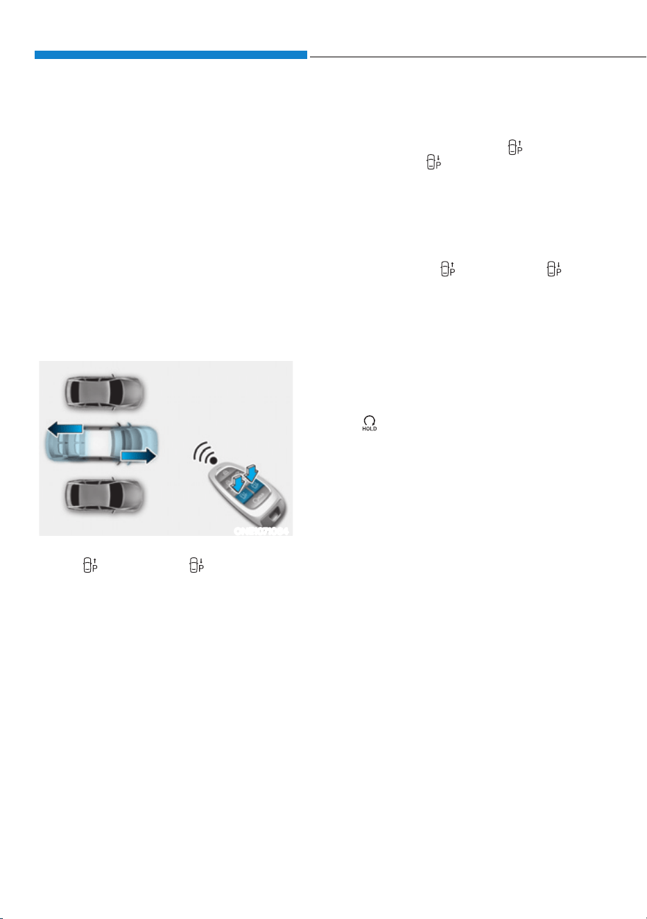
Driver Assistance System
7-154
ś'Agree' must be selected on the
infotainment system screen and the
infotainment system has to operate
properly to use Remote Operation
function.
śMethod (2) can be used after the
vehicle has been driven above 3
mph (5 km/h).
śIf the function is turned on again
after parallel parking is completed
by Remote Smart Parking Assist,
Remote Operation function can be
used with Method (2).
2. Remotely moving forward and
backward
ONE1071064
(1) Press and hold one of the Forward
(
) or Backward ( ) button on
the smart key. Remote Smart
Parking Assist will automatically
control the steering wheel, vehicle
speed and gearshift. The vehicle
will move in the direction of the
button pressed.
(2) While Remote Operation function
is operating, if you do not
hold down the Forward (
) or
Backward ( ) button, the vehicle
will stop and function control
will pause. The function will start
operating again when the button is
pressed and held again.
(3) When the vehicle reaches the
target location, release the smart
key Forward (
) or Backward ( )
button.
(4) When the driver gets in the vehicle
with the smart key, a message
will appear informing the driver
Remote Operation function is
complete on the infotainment
system screen and the vehicle will
remain on.
In addition, when the Remote Start
(
) button is pressed on the smart
key from outside the vehicle, a
message will appear informing the
driver Remote Operation function
is complete and the vehicle will
turn off.

07
7-155
śCheck that all smart keys are
outside the vehicle when using
Remote Operation function.
śRemote Operation function will
operate only when the smart key is
within 13 ft. (4 m) from the vehicle. If
there is no vehicle movement even
when the Forward (
) or Backward
(
) button is pressed on the smart
key, check the distance to the
vehicle and press the button again.
śThe detecting range of the smart
key may vary depending on the
surroundings that are affected by
radio waves such as transmission
tower, broadcast station, etc.
śWhen remotely moving forward
using method (1), it is recognized
as an exit situation, and the
vehicle moves 13 ft. (4 m) to
check for pedestrians, animals or
objects around the vehicle. After
confirmation, the steering wheel
is controlled according to the
condition ahead.
śWhen remotely moving forward
using method (2), it is recognized
as a parking situation, and will
immediately control the steering
wheel according to the condition
ahead to assist with entering the
parking space and aligning the
vehicle. However, performance
may reduce depending on the
pedestrians, animals, shape of
objects, location, etc., around the
vehicle.
śFor moving remotely backward,
both method (1) and (2) aligns the
steering wheel first, and then will
only move the vehicle straight.
śWhen remotely moving forward or
backward is completed, the vehicle
will automatically shift to P (Park)
and engage EPB (Electronic Parking
Brake).
CAUTION
ś When using Remote Operation
function, make sure that all
passengers have gotten out of the
vehicle.
ś If the vehicle’s battery is discharged
or Remote Smart Parking Assist
malfunctions when parked in a
narrow parking space, Remote
Operation function will not operate.
Always park your vehicle in a space
wide enough for you to get in or out
of your vehicle.
ś Please note that depending on the
parking space, you may not be able
to exit from the space you have
entered by using Remote Operation
function.
ś After parking, the surrounding may
change due to the movement of
surrounding vehicles. If this occurs,
Remote Operation function may not
operate.
ś Before leaving the vehicle, close
windows and vision roof, and make
sure the vehicle is off before locking
the doors.

Driver Assistance System
7-156
Remote Operation function operation
status
Operation
status
Smart key LED
Hazard
warning
light
Under
control
Green LED
continuously
blinks
-
Pause
Red LED
continuously
blinks
Blinks
Off
Red LED
illuminates for
4 seconds and
then turns off
Blinks 3
times and
turns off
Complete
Green LED
illuminates for
4 seconds and
then turns off
Blinks 1
time and
turns off
à Operation status by the hazard
warning light may not be applicable
based on the regulation of your
country.
à If the smart key is not within the
operating range from the vehicle
(approximately 13 ft. (4m)), the
smart key LED will not illuminate or
blink. Use the smart key within the
operating range.
How to turn off Remote Operation
function while operating
ś Press the Parking/View ( ) button
while the infotainment system screen
guides the driver using method 2.
ś Shift the gear except to P (Park)
while the infotainment system screen
guides the driver using method 2.
ś Press the Parking Safety (
) button
or select ‘Cancel’ on the infotainment
system screen.
ś Press the Remote Start (
) button
on the smart key while the vehicle is
being controlled by Remote Operation
function. Remote Operation function
will turn off. At this time, the vehicle
will turn off.
ś Get on the vehicle with the smart
key. Remote Operation function will
turn off. At this time, the vehicle will
remain on.
The function will pause in the
following conditions when:
ś There is a pedestrian, animal or object
in the direction the vehicle is moving
ś The door or liftgate is open
ś The Forward (
) or Backward ( )
button is not continuously pressed
ś Simultaneously pressing multiple
buttons on a smart key
ś The smart key is not operated within
13 ft. (4 m) from the vehicle
ś Button of another smart key is pressed
in addition to the operating smart key
(Excluding start button)
ś Blind-Spot Collision-Avoidance
Assist or Rear Cross-Traffic Collision-
Avoidance Assist operates while the
vehicle is being controlled in the
reverse direction.

07
7-157
ś The vehicle moves 22 ft. (7 m) while
the smart key is pressed with Remote
Operation function (maximum travel
distance per button press)
When Remote Operation function is
paused, the vehicle will stop. If the
condition that made the function to
pause disappears, the function may
operate again.
The function will cancel in the
following conditions when:
ś The steering wheel is steered
ś The gear is shifted while the vehicle is
moving
ś Operating EPB while the vehicle is
moving
ś The vehicle hood is open
ś The brake pedal or accelerator pedal
is depressed when all the doors are
closed
ś The smart key is outside the vehicle
when the brake pedal is depressed
while the driver's door is open
ś Rapid acceleration occurs
ś Vehicle skid occurs
ś The wheel is stuck by an obstacle and
cannot move
ś Approximately 3 minutes and 50
seconds has passed after Remote
Operation function has started to
operate
ś The slope of the road exceeds the
operational range
ś The function is paused for more than
1 minute
ś The total travel distance of the vehicle
has exceeded 45 ft. (14 m) after
Remote Operation function operation
ś The steering wheel, gearshift, braking,
and drive controls are not working
properly
ś There is a problem with the smart key
or the smart key battery is low
ś ABS, TCS or ESC system operates due
to slippery road conditions
ś The alarm of the Theft Alarm System
sounds
ś The Charging door opens
ś The EV mode is utility mode
When Remote Operation function is
canceled, the vehicle will automatically
stop, shift the gear to P (Park) and
engage EPB (Electronic Parking Brake).
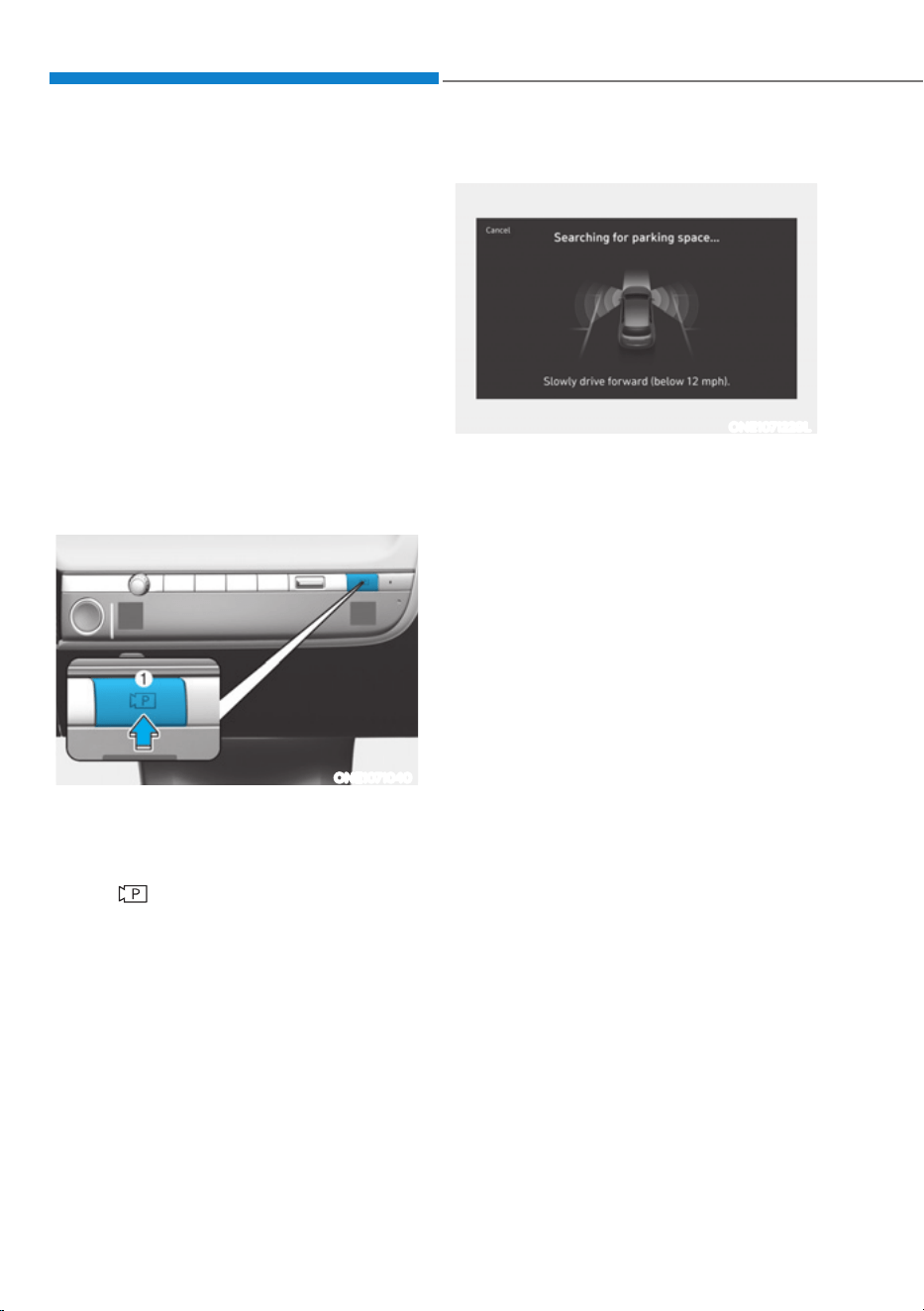
Driver Assistance System
7-158
Smart Parking, Remote Smart
Parking
Operating order
Parking function operates in the
following order:
1. Getting ready for parking
2. Searching for parking space
3. Select parking type and operating
mode
4. Smart Parking
5. Remote Smart Parking
ś Parking function includes Smart
Parking and Remote Smart Parking.
1. Getting ready for parking
ONE1071040
(1) With the vehicle turned on,
depress the brake pedal and shift
the gear to D (Drive) or N (Neutral).
(2) Press and hold the Parking/View
(
) button to turn on Remote
Smart Parking Assist.
ś'Agree' must be selected on the
infotainment system screen and the
infotainment system has to operate
properly to use Parking function.
śIf you drive above 3 mph (5 km/h)
with the vehicle on, you may use
the Parking function with the gear
shifted to N (Neutral).
2. Searching for parking space
ONE1071229L
(1) Slowly drive forward maintaining
the distance of approximately
40 in. (100 cm) from the parked
vehicles.
(2) When searching for a parking
space is complete, a message will
appear on the infotainment system
screen with an audible sound to
notify the search is complete.
(3) ‘Select Parking Type’ will be
displayed on the infotainment
system screen and the selected
parking space will appear on Top
View screen of Surround View
Monitor.
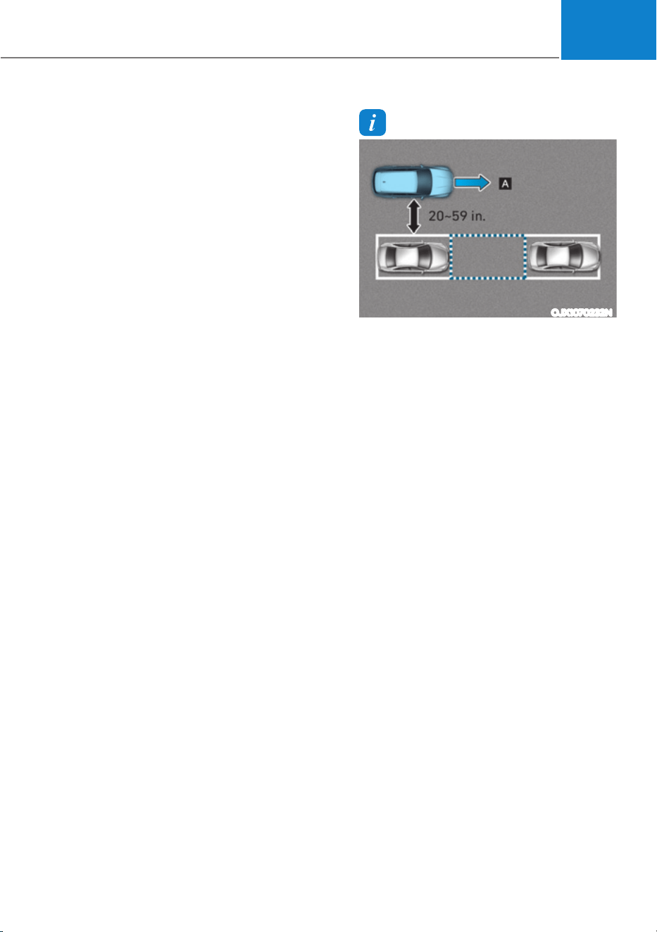
07
7-159
śRemote Smart Parking Assist
searches for parking spaces that are
next to parked vehicles, or parking
spaces with parked vehicles in front
or rear.
śWhile searching for a parking space,
when vehicle speed is above 12 mph
(20 km/h), a message will appear
on the infotainment system screen
informing you to slow down. When
vehicle speed is above 18 mph (30
km/h), Parking function will turn off.
śSearching for a parking space will
be completed when there is enough
space to move the vehicle in
addition to the parking space.
śEven if an audible sound is heard
to notify that searching for a
parking space is complete, search
completion can be canceled
immediately depending on
surroundings.
Information
OJX1070232N
[A] : Searching for parking space
ś If the distance is below 20 in. (50 cm)
or over 59 in. (150 cm), Remote Smart
Parking Assist may not be able to
search for a parking space.
ś If you do not maintain a certain
distance from the parked vehicle, the
performance to search for a parking
space may reduce.
ś Even if a diagonal parking space is
searched as a parking space, parking is
not assisted properly.
ś Due to abnormal performance of the
ultrasonic sensor or the influence of
the surroundings, Parking function
may not be able to search for a parking
space even if there is a parking space,
or may search for a space that is not
suitable for parking.
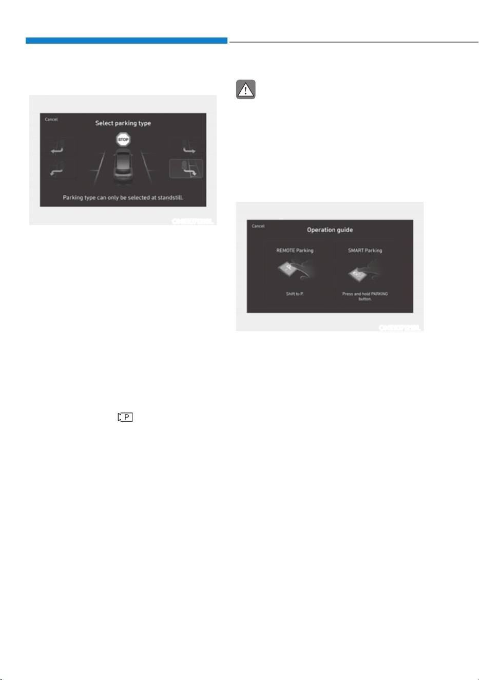
Driver Assistance System
7-160
3. Select parking type and operating mode
ONE1071218L
(1) Parking type – Perpendicular
reverse (Left/Right), Parallel
reverse (Left/Right)
With the vehicle stopped by
depressing the brake pedal, touch
the infotainment system screen to
select the desired parking type.
śIf you continue to drive without
stopping after the parking type
selection screen appears, Remote
Smart Parking Assist will return to
the previous stage and search for a
parking space.
śIf Parking function is canceled
unintentionally by pressing the
Parking/View (
) button before
the parking type is selected, you
can return to the parking type
selection stage by pressing and
holding the button again while the
vehicle is stopped.
CAUTION
Before selecting the Parking type,
the driver should check whether the
parking space is suitable.
If the searched parking space by
Remote Smart Parking Assist is narrow
or unsuitable for parking, do not select
the Parking type and move the vehicle
to search for another parking space.
ONE1071219L
(2) Operating mode – Remote
Parking, Smart Parking
After selecting a parking type,
the infotainment system screen
will guide you with Remote Smart
Parking function and Smart
Parking function. Follow the
instructions to operate Remote
Smart Parking Assist.
śOperating instructions will be
displayed on the screen for each
desired function you select.
śDo not take your foot off the brake
pedal during the Parking function
guide. When the vehicle moves,
Remote Smart Parking Assist will
turn off.
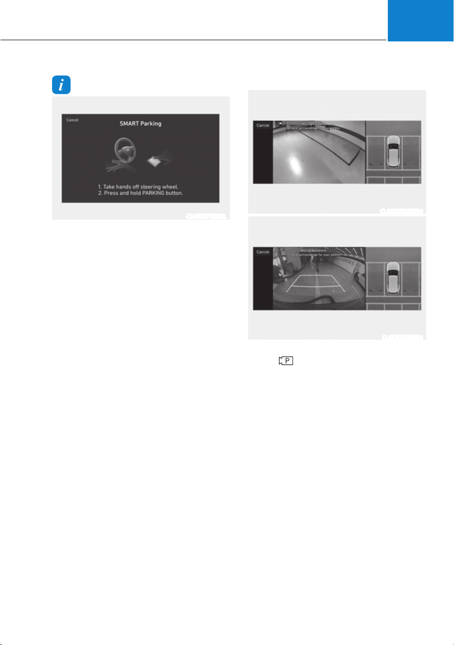
07
7-161
Information
ONE1071220L
If Remote Smart Parking Assist cannot
activate Remote Smart Parking function,
only the Smart Parking guide will be
displayed on the infotainment system
screen.
4. Smart Parking
OJX1070250N
OJX1070251N
(1) Press the Parking/View
(
) button when the vehicle is
stopped by depressing the brake
pedal. When the brake pedal is
released, Remote Smart Parking
Assist will automatically control
the steering wheel, vehicle speed
and gearshift.
(2) While Smart Parking function
is operating, if you do not hold
down the Parking/View button,
the vehicle will stop and function
control will pause. The function
will start operating again when the
Parking/View button is pressed
and held again.
(3) When the vehicle reaches the
target parking position, a message
will appear on the infotainment
system screen to inform you that
parking is complete.
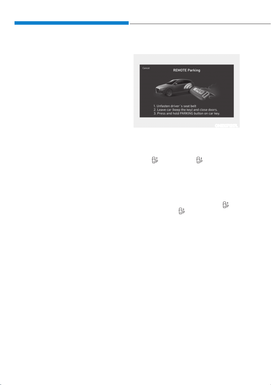
Driver Assistance System
7-162
śSmart Parking function will not
operate if the door is open or the
seat belt is not fastened.
śThe parking location indicator is
displayed on Surround View Monitor
screen and is displayed until the
vehicle enters the parking space
for the first time by Smart Parking
function.
śVehicle speed can be adjusted
by depressing the brake pedal
while Smart Parking function is
operating. However, the vehicle
does not accelerate even when the
accelerator pedal is depressed.
śDepending on parking
environments, if the vehicle is
stopped by a stopper, parking may
be completed.
śIf you need to change the vehicle's
position or location, manually
complete parking your vehicle.
5. Remote Smart Parking
ONE1071217L
(1) Shift the gear to P (Park), get out
of the vehicle with the smart key,
and close all doors.
(2) Press and hold one of the Forward
(
) or Backward ( ) button on
the smart key. Remote Smart
Parking Assist will automatically
control the steering wheel, vehicle
speed and gearshift.
(3) While Remote Smart Parking
function is operating, if you do
not hold down the Forward (
) or
Backward (
) button, the vehicle
will stop and function control
will pause. The function will start
operating again when the button is
pressed and held again.
(4) When the vehicle reaches the
target parking position, a message
will appear on the infotainment
system screen to inform you that
parking is complete. The vehicle
will automatically shift to P (Park),
engage EPB (Electronic Parking
Brake) and the vehicle will turn off.

07
7-163
śWhen operating Remote Smart
Parking function, make sure all
smart keys are outside of the
vehicle.
śRemote Smart Parking function will
operate only when the smart key is
within 13 ft. (4 m) from the vehicle. If
there is no vehicle movement even
when the Remote Operation button
is pressed on the smart key, check
the distance to the vehicle and
press the button again.
śThe detecting range of the smart
key may vary depending on the
surroundings that are affected by
radio waves such as transmission
tower, broadcast station, etc.
śThe parking location indicator is
displayed on Surround View Monitor
screen and is displayed until the
vehicle enters the parking space
for the first time by Remote Smart
Parking function.
śDepending on parking
environments, if the vehicle is
stopped by a stopper, parking may
be completed.
śIf you need to change the vehicle's
position or location, manually
complete parking your vehicle.
CAUTION
ś When using Remote Smart Parking
function, make sure that all
passengers have gotten out of the
vehicle.
ś After ending or turning off Remote
Smart Parking function, before
leaving the vehicle, close windows
and vision roof, and make sure the
vehicle is off before locking the
doors.
How to turn off Parking function
while operating
ś Press the Parking/View ( ) button in
the following stage:
- Searching for parking space
- Select parking type
ś Shift the gear to R (Reverse) in the
following stage:
- Searching for parking space
- Select parking type
- Select operating mode
ś Press the Parking Safety (
) button
or select ‘Cancel’ on the infotainment
system screen to turn off Parking
function.
ś While Smart Parking function is
operating:
- If the vehicle is stopped by
depressing the brake pedal, and the
gear is shifted, Parking function will
turn off. At this time, EPB (Electronic
Parking Brake) will not be engaged.
ś While Remote Smart Parking function
is operating:
- Press the Remote Start (
) button
on the smart key. Parking function
will turn off.
- Get on the vehicle with the smart
key. Parking function will turn off. At
this time, the vehicle will remain on.

Driver Assistance System
7-164
Parking function operation status
ś Smart Parking function
Operation
status
Turn signal
Under control
The turn signal of the parking direction blinks until the first reverse
is complete.
ś Smart Parking function
Operation
status
Smart key
LED
Hazard
warning
light
Turn signal
Under control
Green LED
continuously
blinks
-
The turn signal of the parking direction blinks
until the first reverse is complete.
Pause
Red LED
continuously
blinks
Blinks -
Off
Red LED
illuminates
for 4 seconds
and then
turns off
Blinks 3
times and
turns off
-
Complete
Green LED
illuminates
for 4 seconds
and then
turns off
Blinks 1
time and
turns off
-
à Operation status by the hazard warning light may not be applicable based on the
regulation of your country.
à If the smart key is not within the operating range from the vehicle (approximately 13
ft. (4 m)), the smart key LED will not illuminate or blink. Use the smart key within the
operating range.

07
7-165
The function will pause in the
following conditions when:
ś Smart Parking
- There is a pedestrian, animal or
object in the direction the vehicle is
moving
- The door or liftgate is open
- The driver’s seat belt is not fastened
- Blind-Spot Collision-Avoidance
Assist or Rear-Cross Traffic
Collision-Avoidance Assist operates
while the vehicle is being controlled
in the reverse direction
- The Parking/View (
) button is not
continuously pressed
- The vehicle is stopped by
depressing the brake pedal
ś Remote Smart Parking
- There is a pedestrian, animal or
object in the direction the vehicle is
moving
- The door or liftgate is open
- The Forward (
) or Backward ( )
button is not continuously pressed
- Simultaneously pressing multiple
buttons on a smart key
- The smart key is not operated within
13 ft. (4 m) from the vehicle
- Button of another smart key is
pressed in addition to the operating
smart key
- Blind-Spot Collision-Avoidance
Assist or Rear-Cross Traffic
Collision-Avoidance Assist operates
while the vehicle is being controlled
in the reverse direction
When Parking function is paused, the
vehicle will automatically stop. If the
condition that made the function to
pause disappears, the function may
operate again.
The function will cancel in the
following conditions when:
ś Smart Parking
- The steering wheel is steered
- The gear is shifted while the vehicle
is moving
- Operating EPB while the vehicle is
moving
- The hood is open
- The driver opens the door with the
seatbelt unfastened
- Rapid acceleration occurs
- Vehicle skid occurs
- The wheel is stuck by an obstacle
and cannot move
- There are pedestrians, animals or
objects at the front and rear of the
vehicle at the same time
- Approximately 3 minutes and 50
seconds have past after Smart
Parking function has started to
operate
- The slope of the road exceeds the
operational range
- The function is paused for more
than 1 minute
- The steering wheel, gearshift,
braking, and drive controls are not
working properly
- ABS, TCS or ESC system operates
due to slippery road conditions
- The Charging door opens
- The EV mode is utility mode
When Smart Parking function is
canceled, the vehicle will automatically
stop, shift the gear to P (Park) and
engage EPB (Electronic Parking Brake).
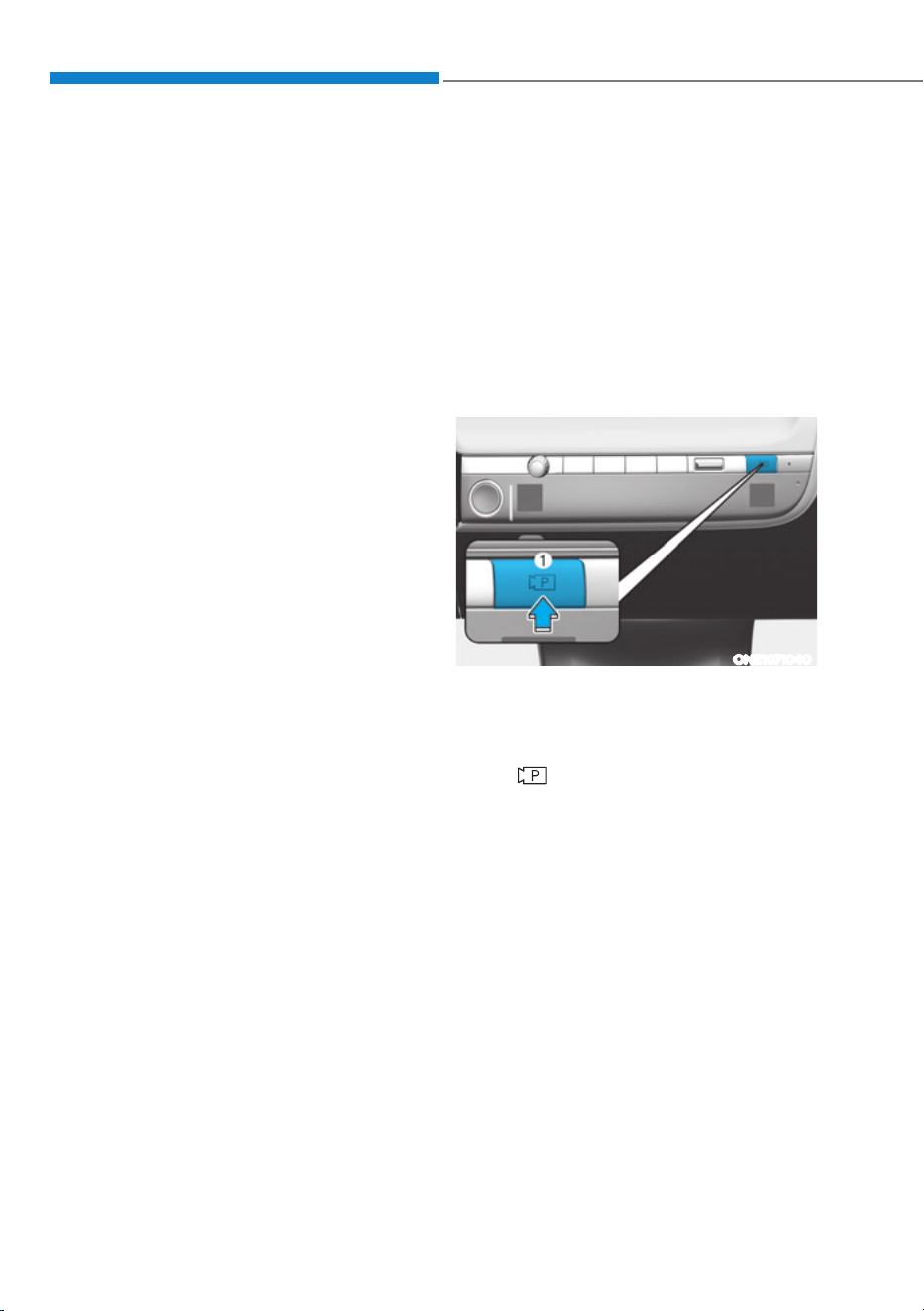
Driver Assistance System
7-166
ś Remote Smart Parking
- The steering wheel is steered
- The gear is shifted
- Operating EPB while the vehicle is
moving
- The hood is open
- The brake pedal or accelerator
pedal is depressed when all the
doors are closed
- The smart key is outside the vehicle
when the brake pedal is depressed
while the driver's door is open.
- Rapid acceleration occurs
- Vehicle skid occurs
- The wheel is stuck by an obstacle
and cannot move
- There are pedestrians, animals or
objects at the front and rear of the
vehicle at the same time
- Approximately 3 minutes and 50
seconds have past after Remote
Smart Parking function has started
to operate
- The slope of the road exceeds the
operational range
- The function is paused for more
than 1 minute
- The steering wheel, gearshift,
braking, and drive controls are not
working properly
- There is a problem with the smart
key or the smart key battery is low
- ABS, TCS or ESC system operates
due to slippery road conditions
- The alarm of the Theft Alarm System
sounds
- The Charging door opens
- The EV mode is utility mode
When Remote Smart Parking function is
canceled, the vehicle will automatically
stop, shift the gear to P (Park) and
engage EPB (Electronic Parking Brake).
Smart Exit
Operating order
Smart Exit function operates in the
following order:
1. Getting ready for exit
2. Checking space
3. Select exit direction
4. Smart Exit
1. Getting ready for exit
ONE1071040
(1) With the vehicle turned on,
depress the brake pedal and shift
the gear to P (Park) or N (Neutral).
(2) Press and hold the Parking/View
(
) button to turn on Remote
Smart Parking Assist.
ś'Agree' must be selected on the
infotainment system screen and the
infotainment system has to operate
properly to use Smart Smart Exit
function.
śDrive below 3 mph (5 km/h) with
the vehicle on and shift the gear to
N (Neutral), Smart Exit function can
be used.
śIf the function is turned on again
after parallel parking is completed
by Remote Smart Parking Assist,
Smart Exit function can be used.
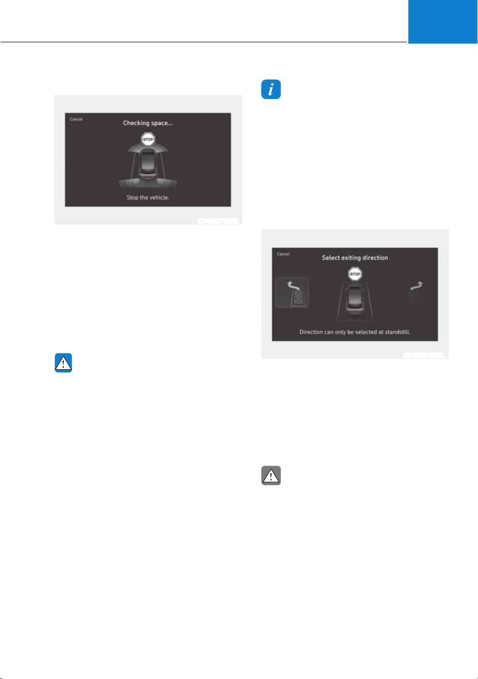
07
7-167
2. Checking space
ONE1071221L
(1) When the vehicle is stopped by
depressing the brake pedal, the
vehicle sensors will detect the
distance from nearby objects and
check for space to exit.
(2) When checking for space is
complete, a message will appear
on the infotainment system screen
with an audible sound to notify the
search is complete.
WARNING
ś While checking for space, if there is
a risk of collision with pedestrian,
animal or object in the direction of
vehicle exit, for your safety, Smart
Exit function can be turned off.
ś Even if check for space is completed,
objects in the blind spot area cannot
be detected by the sensors. The
driver must directly check the blind
spot area and continue using the
function.
Information
Due to abnormal performance of the
ultrasonic sensor or the influence of the
surroundings, Parking function may not
be able to search for a parking space even
if there is a parking space, or may search
for a space that is not suitable for parking.
- The parked vehicle has objects attached
to the bumper such as bumper guard,
trailer hitch, etc.
3. Select exiting direction
ONE1071222L
(1) With the vehicle stopped by
depressing the brake pedal, the
infotainment system screen
displays the possible directions for
parallel exit.
(2) Touch the infotainment system
screen to select the desired exit
direction.
CAUTION
ś Before selecting the Exit Direction,
the driver should check whether the
space for exit is suitable.
ś If the searched exit space by Remote
Smart Parking Assist is narrow or
unsuitable (surrounding vehicles are
parked vertically, etc.), do not use
the Smart Exit function.
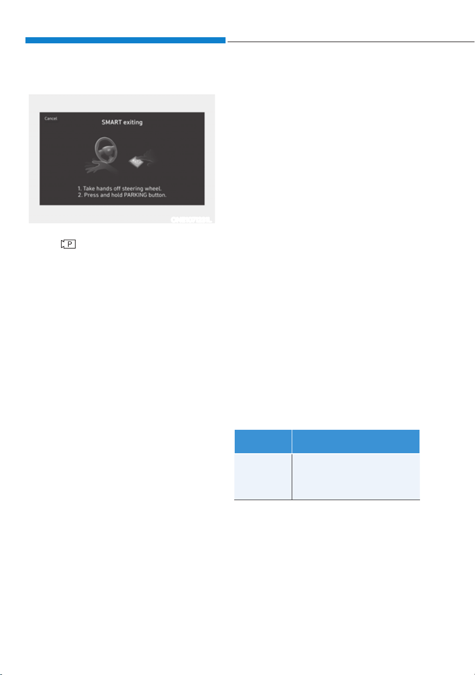
Driver Assistance System
7-168
4. Smart Exit
ONE1071231L
(1) Press the Parking/View
(
) button when the vehicle is
stopped by depressing the brake
pedal. When the brake pedal is
released, Remote Smart Parking
Assist will automatically control
the steering wheel, vehicle speed
and gearshift.
(2) While Smart Exit function is
operating, if you do not hold
down the Parking/View button,
the vehicle will stop and function
control will pause. The function
will start operating again when the
Parking/View button is pressed
and held again.
(3) When the vehicle reaches the
target exit location, a message will
appear on the infotainment system
screen to inform you that exit is
complete.
śSmart Exit function will not operate
if the door is open or the seat belt is
not fastened.
śVehicle speed can be adjusted
by depressing the brake pedal
while Smart Exit function is
operating. However, the vehicle
does not accelerate even when the
accelerator pedal is depressed.
śIf exit is completed while
depressing the brake pedal, Smart
Exit function will complete with the
gear in D (Drive).
śIf exit is completed while depressing
the accelerator pedal, you must
take your foot off the accelerator
pedal once for the accelerator pedal
to operate.
śIf there is no vehicle operation such
as depressing the brake pedal or
accelerator pedal within 4 seconds
after exit is complete, the vehicle
will automatically shift to P (Park)
and engage EPB (Electronic Parking
Brake).
śAfter Exit function is complete,
always check the surroundings
before driving.
Smart Exit operation status
Operation
status
Turn signal
Under
control
The turn signal of the exit
direction blinks until the exit
is complete or Smart Exit is
canceled.

07
7-169
How to turn off Smart function while
operating
ś Press the Parking/View ( ) button in
the following stage:
- Checking space
- Select exit direction
ś Shift the gear to R (Reverse) in the
following stage:
- Checking space
- Select exit direction
ś Press the Parking Safety (
) button
or select ‘Cancel’ on the infotainment
system screen to turn off Exit
function.
ś While Smart Exit function is operating,
if the vehicle is stopped by depressing
the brake pedal, and the gear is
shifted, Exiting function will turn off.
At this time, EPB (Electronic Parking
Brake) will not be engaged.
The function will pause in the following
conditions when:
ś There is a pedestrian, animal or object
in the direction the vehicle is moving
ś The door or liftgate is open
ś The driver’s seat belt is not fastened
ś Blind-Spot Collision-Avoidance
Assist or Rear-Cross Traffic Collision-
Avoidance Assist operates while the
vehicle is being controlled in the
reverse direction
ś The Parking/View (
) button is not
continuously pressed
ś The vehicle is stopped by depressing
the brake pedal
When Exit function is paused, the vehicle
will stop. If the condition that made
the function to pause disappears, the
function may operate again.
The function will cancel in the following
conditions when:
ś Smart Exit
- The steering wheel is steered
- The gear is shifted while the vehicle
is moving
- Operating EPB while the vehicle is
moving
- The hood is open
- The driver opens the door with the
seatbelt unfastened
- Rapid acceleration occurs
- Vehicle skid occurs
- The wheel is stuck by an obstacle
and cannot move
- There are pedestrians, animals or
objects at the front and rear of the
vehicle at the same time
- Approximately 3 minutes and 50
seconds have past after Smart Exit
function has started to operate
- The slope of the road exceeds the
operational range
- The function was paused for more
than 1 minute
- The steering wheel, gearshift,
braking, and drive controls are not
working properly
- ABS, TCS or ESC system operates
due to slippery road conditions
- The Charging door opens
When Smart Exit function is canceled,
the vehicle will automatically stop, shift
the gear to P (Park) and engage EPB
(Electronic Parking Brake).
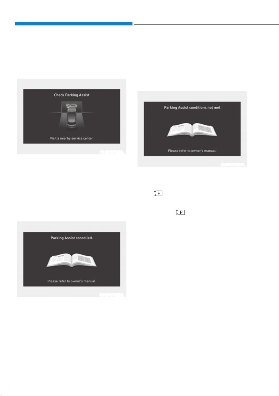
Driver Assistance System
7-170
Remote Smart Parking Assist
Malfunction and Limitations
Remote Smart Parking Assist
malfunction
ONE1071223L
Remote Smart Parking Assist check
When Remote Smart Parking Assist is
not working properly, the ‘Check Parking
Assist’ warning message will appear on
the infotainment system screen. If the
message appears, stop using Remote
Smart Parking Assist, and have the
vehicle be inspected by an authorized
HYUNDAI dealer.
ONE1071228L
Remote Smart Parking Assist canceled
When Remote Parking Assist is
operating, the function can be canceled,
and the ‘Parking Assist Canceled’
warning message may appear regardless
of the parking order. Other messages
may appear depending on the situations.
Follow the instructions provided on
the infotainment system screen while
parking your vehicle with Remote
Parking Assist. Always look around and
pay attention when using Remote Smart
Parking Assist.
ONE1071227L
Remote Smart Parking Assist standby
When ‘Parking Assist Conditions Not
Met’ message appears, when Parking/
View (
) button has been pressed and
held, Remote Smart Parking Assist is in
standby. After a while, press and hold the
Parking/View (
) button again to see if
Remote Smart Parking Assist works.
The message appears even when the
smart key's battery is low. Check the
smart key battery level.
It does not work even when the EV
mode is in the Utility mode. For related
information refer to Utility Mode in
‘Foreword/Electric Vehicle System
Overview’.

07
7-171
Limitations of Remote Smart Parking
Assist
In the following circumstances, Remote
Smart Parking Assist performance to
park or exit the vehicle may be limited,
there may be a risk of collision, or
Remote Smart Parking Assist may turn
off. Park or exit the vehicle manually if
necessary.
ś An object is attached to the steering
wheel
ś The vehicle is installed with a snow
chain, spare tire or different size
wheel
ś Tire pressure is lower or higher than
the standard tire pressure
ś Your vehicle is loaded with cargo
longer or wider than your vehicle or a
trailer is connected to your vehicle
ś There is a problem with the wheel
alignment
ś Your vehicle is leaned severely to one
side
ś Your vehicle is equipped with a trailer
hitch
ś The license plate is installed
differently from the original location
ś There is a person, animal or object
above or below the ultrasonic sensor
when Remote Smart Parking Assist is
activated
ś The parking space is curved or
diagonal
ś There is an obstacle such as a person,
animal or object (trash can, bicycle,
motorcycle, shopping cart, narrow
pillar, etc.) near the parking space
ś There is a circular pillar or narrow
pillar, or a pillar surrounded by objects
such as fire extinguisher, etc., near the
parking space
ś The road surface is bumpy (curbstone,
speed bump, etc.)
ś The road is slippery
ś The parking space is near a vehicle
with higher ground clearance or big,
such as a truck, etc.
ś The parking space is Inclined
ś There is heavy wind
ś Operating Remote Smart Parking
Assist on uneven roads, gravel roads,
bushes, etc.
ś The performance of the ultrasonic
sensor is affected by extremely hot or
cold weather
ś The ultrasonic sensor is covered with
snow or water
ś An object that generates ultrasonic
waves is nearby
ś A wireless device with a transmission
function operates near the ultrasonic
sensors
ś Your vehicle is affected by another
vehicle’s Parking Distance Warning
ś The sensor is mounted or positioned
incorrectly by an impact to the
bumper
ś When the ultrasonic sensor cannot
detect the following objects:
- Sharp or slim objects, such as ropes,
chains or small poles
- Objects smaller than 40 in. (100 cm)
in length and narrower than 6 in. (14
cm) in diameter
- Objects which tend to absorb
sensor frequency, such as clothes,
spongy material or snow
- A narrow object such as a corner of
a square pillar
- Person, animal or object near the
ultrasonic sensor
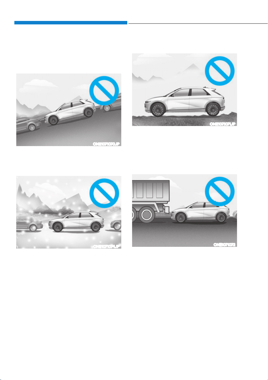
Driver Assistance System
7-172
Remote Smart Parking Assist may not
operate properly under the following
circumstances:
ś Parking on inclines
ONE1071070JP
Park manually when parking on
inclines.
ś Parking in snow
ONE1071074JP
Snow may interfere with sensor
operation, or Remote Smart Parking
Assist may cancel if the road is
slippery while parking.
ś Parking on uneven road
ONE1071071JP
Remote Smart Parking Assist may
cancel when the vehicle slips, or
the vehicle cannot move due to
road conditions such as pebbles or
fragmented stones.
ś Parking behind a truck
ONE1071072
Do not use Remote Smart Parking
Assist around vehicles with higher
ground clearance, such as a bus,
truck, etc. It may lead to an accident.
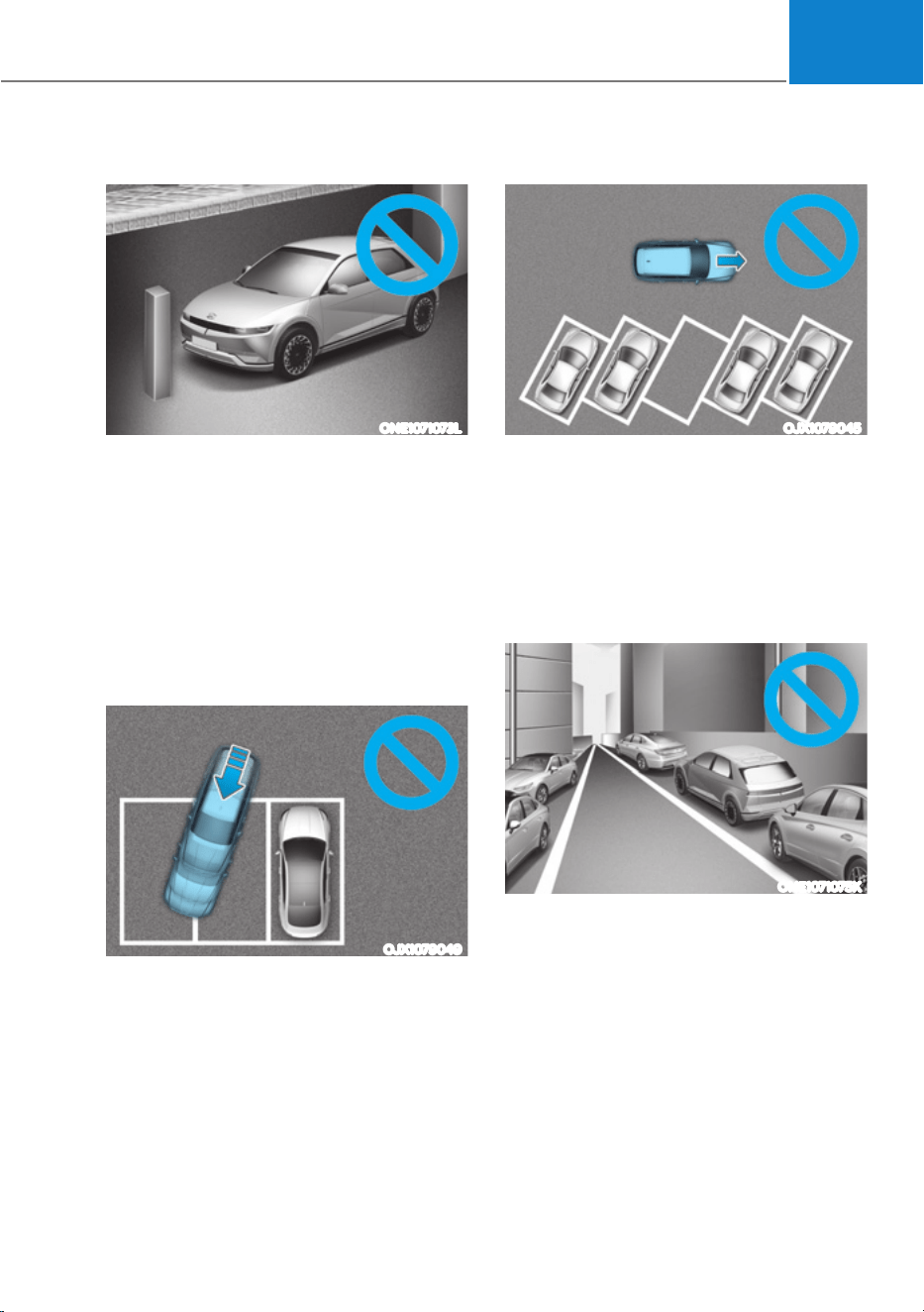
07
7-173
ś Parking near a pillar
ONE1071073L
Remote Smart Parking Assist
performance may reduce or collision
with an obstacle may occur when
there is a narrow object, circular pillar,
square pillar, or a pillar surrounded
by objects such as a fire extinguisher,
etc., near the parking space. The
driver should park the vehicle
manually.
ś Parking in a parking space with a
vehicle on one side only
OJX1079049
If Remote Smart Parking Assist is
used, when parking in a parking space
with a vehicle only on one side, your
vehicle may cross the parking line to
avoid the parked vehicle.
ś Parking diagonal
OJX1079045
Remote Smart Parking Assist does not
provide diagonal parking. Even if your
vehicle was able to enter the parking
space, do not use Remote Smart
Parking Assist because the function
cannot operate properly.
ś Leaving a parking space near a wall or
parking in a narrow space
ONE1071075K
- Remote Smart Parking Assist my
not operate properly when leaving
a parking space that is narrow
and near a wall. Always check for
pedestrians, animals, objects while
leaving.
- For your safety, Remote Smart
Parking Assist does not search for
parking spaces at areas with narrow
parking spaces that are narrower
than the minimum space required
for parking.

Driver Assistance System
7-174
WARNING
Take the following precautions when
using Remote Smart Parking Assist:
ś The driver is responsible for safe
parking and exit when using Remote
Smart Parking Assist.
ś When using Remote Smart Parking
Assist, stay out of the way in the
direction the vehicle moves for your
safety.
ś Always check surroundings when
using Remote Smart Parking Assist.
You may collide with pedestrians,
animals, or objects if they are near
the sensor or are in the sensor’s blind
spot area.
ś A collision may occur if a pedestrian,
animal, or object suddenly appears
while Remote Smart Parking Assist is
operating.
ś Do not use Remote Smart Parking
Assist when under the influence of
alcohol.
ś Do not let children or other people to
use the smart key.
ś If Remote Smart Parking Assist is
used continuously for a long period,
it may adversely affect Remote
Smart Parking Assist performance.
ś Remote Smart Parking Assist may not
operate properly if the vehicle needs
wheel alignment adjustment such
as when the vehicle tilts to one side.
Have the vehicle be inspected by an
authorized HYUNDAI dealer.
ś Noise may be heard when braking
occurs by Remote Smart Parking
Assist or when the brake pedal is
depressed by the driver.
ś Remote Smart Parking Assist may
suddenly apply the brake to avoid
collision.
ś Use Remote Smart Parking Assist
only in a parking space that is large
enough for the vehicle to move
safely.
NOTICE
ś If the 3rd stage warning (continuous
beep) of the Forward/Reverse
Parking Distance Warning sounds
while Remote Smart Parking
Assist is operating, it means the
obstacle detected is close to your
vehicle. At this time, Remote Smart
Parking Assist will temporarily stop
operating. Make sure there are no
pedestrians, animals, or objects
around your vehicle.
ś Depending on brake operation, the
stop lights may come on while the
vehicle is moving.
ś If the vehicle is remotely started that
has been parked in cold weather for
a long time, the operation of Remote
Smart Parking function may be
delayed or canceled depending on
vehicle condition.
07
7-175
'(&/$5$7,212)&21)250,7<ǣ,)(48,33('Ǥ
Front Radar
The radio frequency components (front
radar) complies:
- For USA, Micronesia, Dominican
Republic and Honduras
OANATEL342
- For Canada
OANATEL343
Driver Assistance System
7-176
Rear Corner Radar
The radio frequency components (Rear
Corner Radar) complies:
- For USA, Micronesia, Dominican
Republic and Honduras
OANATEL352
- For Canada
OANATEL353

8
Hazard Warning Flasher ................................................................................... 8-2
In Case of an Emergency While Driving .......................................................... 8-2
If the Vehicle Stalls While Driving ...............................................................................8-2
If the Vehicle Stalls at A Crossroad or Crossing .........................................................8-2
If You Have a Flat Tire While Driving ...........................................................................8-3
If the vehicle will not start ................................................................................ 8-3
Confirm the EV Battery is not Low on the Charge Gauge .........................................8-3
Jump Starting (12V battery) .............................................................................8-4
Tire Pressure Monitoring System (TPMS) .........................................................8-7
Check Tire Pressure ......................................................................................................8-7
Tire Pressure Monitoring System ............................................................................... 8-8
Low Tire Pressure Warning Light ................................................................................ 8-9
Low Tire Pressure Position and Tire Pressure Telltale ............................................... 8-9
TPMS (Tire Pressure Monitoring System) Malfunction Indicator ............................ 8-10
Changing a Tire with TPMS ....................................................................................... 8-10
If You have a Flat Tire (with Tire Mobility Kit) .................................................8-12
Introduction ................................................................................................................ 8-12
Notes on the Safe Use of the Tire Mobility Kit ......................................................... 8-13
Components of the Tire Mobility Kit ......................................................................... 8-14
Using the Tire Mobility Kit When a Tire is Flat .......................................................... 8-15
How to Adjust Tire Pressure ...................................................................................... 8-18
Towing ..............................................................................................................8-19
Towing Service ........................................................................................................... 8-19
Removable Towing Hook .......................................................................................... 8-20
8. Emergency Situations
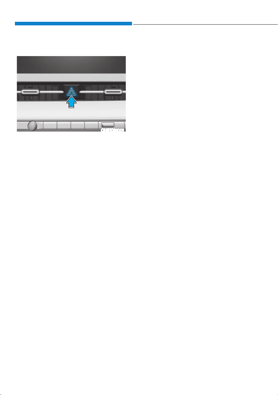
Emergency Situations
8-2
ONE1081001
The hazard warning flasher serves as
a warning to other drivers to exercise
extreme caution when approaching,
overtaking, or passing your vehicle.
It should be used whenever emergency
repairs are being made or when the
vehicle is stopped near the edge of a
roadway.
To turn the hazard warning flasher on
or off, press the hazard warning flasher
button with the Start/Stop button in any
position. The hazard warning flasher
button is located in the center fascia
panel. All turn signal lights will flash
simultaneously.
ś The hazard warning flasher operates
regardless of whether your vehicle is
running or not.
ś The turn signals do not work when the
hazard flasher is on.
If the Vehicle Stalls While Driving
ś Reduce your speed gradually, keeping
a straight line. Move cautiously off the
road to a safe place.
ś Turn on your hazard warning flasher.
ś Try to start the vehicle again. If your
vehicle will not start, contact an
authorized HYUNDAI dealer or seek
other qualified assistance.
If the Vehicle Stalls at A
Crossroad or Crossing
If the vehicle stalls at a crossroads or
crossing, if safe to do so, shift the gear to
N (Neutral) and then push the vehicle to
a safe location.
To stay N (Neutral) while the vehicle is
off, refer to ‘To stay in N (Neutral) when
vehicle is OFF’ in chapter 6.
HAZARD WARNING
FLASHER
IN CASE OF AN EMERGENCY
WHILE DRIVING

08
8-3
If You Have a Flat Tire While
Driving
If a tire goes flat while you are driving:
ś Take your foot off the accelerator
pedal and let the vehicle slow down
while driving straight ahead. Do not
apply the brakes immediately or
attempt to pull off the road as this
may cause loss of vehicle control
resulting in an accident. When the
vehicle has slowed to such a speed
that it is safe to do so, brake carefully
and pull off the road. Drive off the
road as far as possible and park on
firm, level ground. If you are on a
divided highway, do not park in the
median area between the two traffic
lanes.
ś When the vehicle is stopped, press the
hazard warning flasher button, shift
the gear to P (Park), apply the parking
brake, and press the Start/Stop button
to the OFF position.
ś Have all passengers get out of the
vehicle. Be sure they all get out on the
side of the vehicle that is away from
traffic.
ś When changing a flat tire, follow the
instructions provided later in this
chapter.
IF THE VEHICLE WILL NOT
START
Confirm the EV Battery is not
Low on the Charge Gauge
ś Be sure the gear is in P (Park). The
vehicle starts only when the gear is in
P (Park).
ś Check the 12-volt battery connections
to be sure they are clean and tight.
ś Turn on the interior light. If the light
dims or goes out when you operate
the starter, the 12V battery is drained.
Do not push or pull the vehicle to start it.
This could cause damage to your vehicle.
Emergency Situations
8-4
Jump starting can be dangerous if done
incorrectly. Follow the jump starting
procedure in this section to avoid serious
injury or damage to your vehicle. If in
doubt about how to properly jump start
your vehicle, have a service technician or
towing service do it for you.
WARNING
To prevent SERIOUS INJURY or DEATH
to you or bystanders, always follow
these precautions when working near
or handling the battery:
Always read and follow
instructions carefully when
handling a battery.
Wear eye protection designed
to protect the eyes from acid
splashes.
Keep all flames, sparks, or
smoking materials away from
the battery.
Hydrogen is always present
in battery cells, is highly
combustible, and may explode
if ignited.
Keep batteries out of reach of
children.
Batteries contain sulfuric acid
which is highly corrosive. Do
not allow acid to contact your
eyes, skin or clothing.
If acid gets into your eyes, flush your
eyes with clean water for at least 15
minutes and get immediate medical
attention. If acid gets on your skin,
thoroughly wash the area. If you feel
pain or a burning sensation, get medical
attention immediately.
ś When lifting a plastic-cased battery,
excessive pressure on the case may
cause battery acid to leak. Lift with a
battery carrier or with your hands on
opposite corners.
ś Do not attempt to jump start your
vehicle if your battery is frozen.
ś NEVER attempt to recharge the
battery when the vehicle’s battery
cables are connected to the battery.
ś The electrical ignition system works
with high voltage.
NEVER touch these components
with the vehicle running or when
the Start/Stop button is in the ON
position.
ś The electrical ignition system works
with high voltage. NEVER touch
these components with the (
)
indicator ON or when the START/
STOP button is in the ON position.
ś Do not allow the (+) and (-) jumper
cables to touch. It may cause sparks.
ś The battery may rupture or explode
when you jump start with a low or
frozen battery.
ś Do not directly connect the (-) to the
jump cable. Connect the (-) to the
one of the metallic parts located far
from the jump cable in the vehicle.
The direct (-) connection to the jump
cable may cause an explosion.
ś Be sure to use only 12V battery to
jump start. Using batteries with other
voltages to jump start can damage
the battery or even provoke an
explosion.
-80367$57,1*ǣ9%$77(5<Ǥ
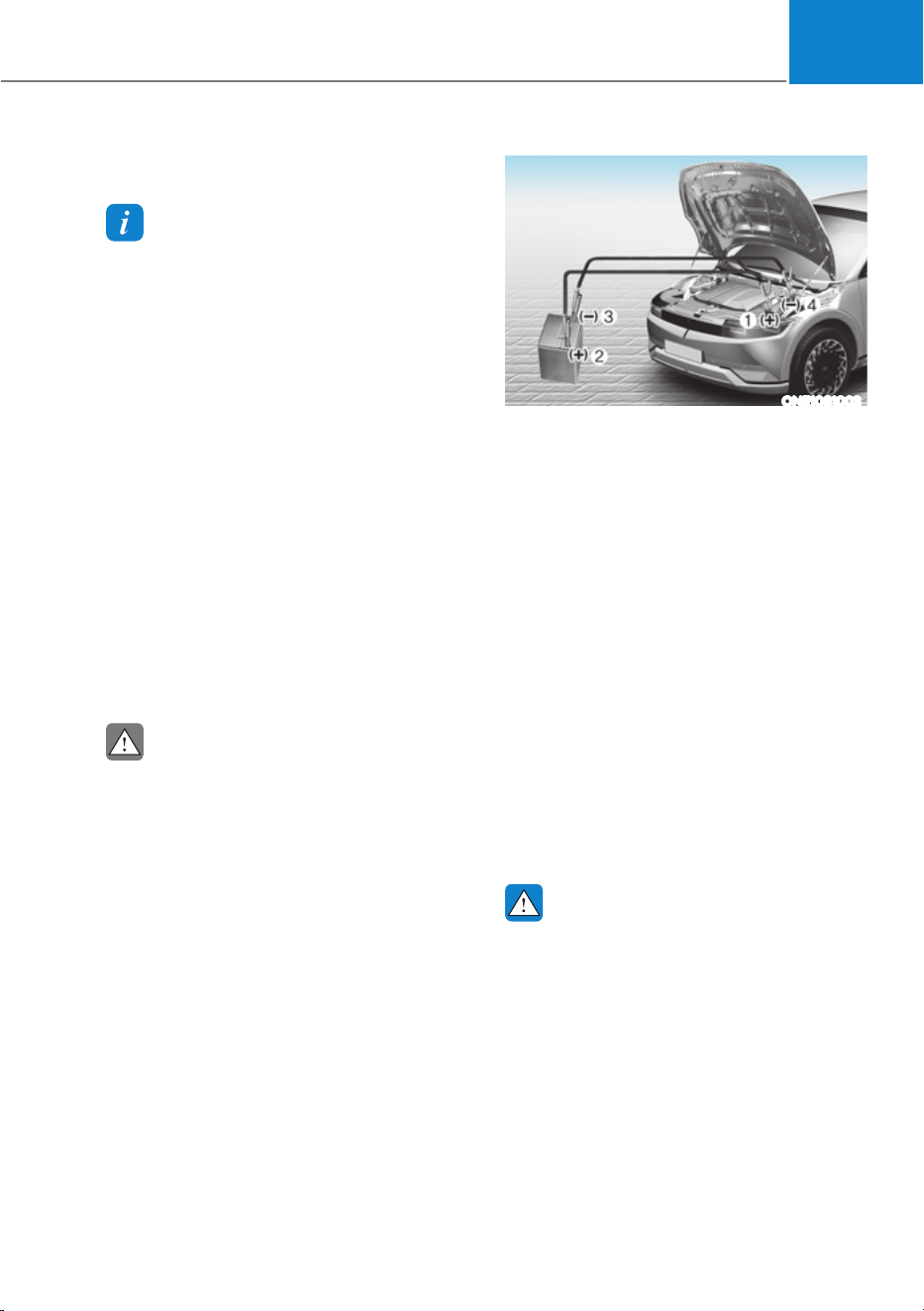
08
8-5
Jump starting procedure
Information
When you jump start your vehicle,
use the jumper terminal in the motor
compartment.
1. Position the vehicles close enough
that the jumper cables will reach, but
do not allow the vehicle body parts to
contact.
2. Avoid fans or any moving parts in the
motor compartment at all times, even
when the vehicles are turned off.
3. Turn off all electrical devices such as
radios, lights, air conditioning, etc.
Put the vehicles in P (Park) and set the
parking brake. Turn both vehicles OFF.
4. Open the hood.
5. Remove the battery cover located
inside of the front trunk.
6. Remove the motor compartment fuse
box cover.
CAUTION
Before jump starting, make sure to
correctly identify the positive (+) and
negative (-) terminals to avoid reverse
polarity connections.
ONE1081003
7. Connect the jumper cables in
the exact sequence shown in the
illustration. First connect one jumper
cable to the red, positive (+) jumper
terminal of your vehicle (1).
8. Connect the other end of the jumper
cable to the red, positive (+) battery/
jumper terminal of the assisting
vehicle (2).
9. Connect the second jumper cable to
the black, negative (-) battery/jumper
terminal of the assisting vehicle (3).
10.
Connect the other end of the second
jumper cable to the black, negative (-)
chassis ground of your vehicle (4).
Do not allow the jumper cables to
contact anything except the correct
battery or jumper terminals or the
correct ground. Do not lean over the
battery when making connections.
WARNING
Do not connect the jumper cable to
the negative (-) jumper terminal of the
discharged battery. A spark could cause
the battery to explode and lead to a
personal injury or vehicle damage.

Emergency Situations
8-6
11.
Start the assisting vehicle and let
it run at approximately for a few
minutes. Then start your vehicle.
12.
Keep your vehicle operating for at
least 30 minutes at idle or driving to
assure your battery receives enough
charge to be able to start on its
own after the vehicle is shut off. A
complete dead battery may require
as long as 60 minutes runtime to fully
recharge it. If vehicle is run for less,
the battery may not restart.
If your vehicle will not start after a few
attempts, it probably requires servicing.
In this event please seek qualified
assistance. If the cause of your battery
discharging is not apparent, have your
vehicle checked by an authorized
HYUNDAI dealer.
Disconnect the jumper cables in the
exact reverse order you connected them:
1. Disconnect the jumper cable from the
black, negative (-) chassis ground of
your vehicle (4).
2. Disconnect the other end of the
jumper cable from the black, negative
(-) battery/chassis ground of the
assisting vehicle (3).
3. Disconnect the second jumper cable
from the red, positive (+) battery/
jumper terminal of the assisting
vehicle (2).
4. Disconnect the other end of the
jumper cable from the red, positive (+)
jumper terminal of your vehicle (1).
Information
An inappropriately disposed
battery can be harmful to
the environment and human
health. Dispose of the battery
according to your local law(s) or
regulations.
NOTICE
To prevent damage to your vehicle:
ś Only use a 12-volt power supply
(battery or jumper system) to jump
start your vehicle.
ś Do not attempt to jump start your
vehicle by push-starting.
ś Always be sure that the battery
cover and cable are tightened after
finishing jump start your vehicle.
Otherwise is may cause damage to
the relevant parts, noise trouble, or
entrance of foreign substances.
CAUTION
While jump starting your vehicle, avoid
the positive (+) and negative (-) cables
to come in contact. A spark could cause
personal injury.
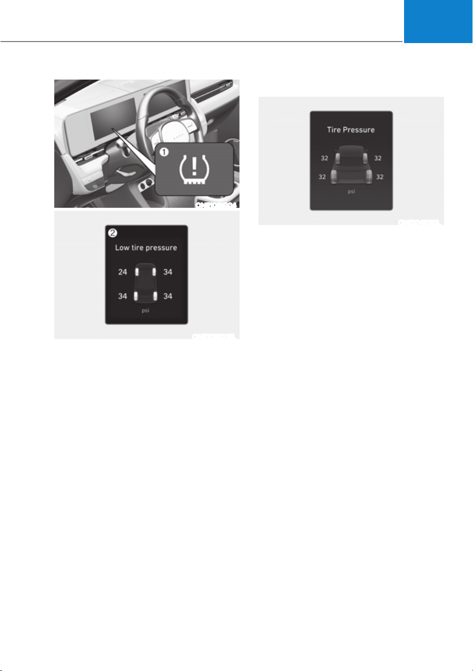
08
8-7
ONE1081004
ONE1081005L
(1) Low Tire Pressure Telltale/TPMS
Malfunction Indicator
(2) Low Tire Pressure Position Telltale
and Tire Pressure Telltale (Shown on
the LCD display)
Check Tire Pressure
ONE1041010L
ś You can check the tire pressure in the
Utility view on the cluster.
Refer to the “View Modes” section in
chapter 4.
ś Tire pressure is displayed after a few
minutes of driving after initial vehicle
start up.
ś If tire pressure is not displayed when
the vehicle is stopped, ‘Drive to
display’ message will appear. After
driving, check the tire pressure.
ś The displayed tire pressure values may
differ from those measured with a tire
pressure gauge.
ś You can change the tire pressure
unit from the Settings menu in the
infotainment system screen. Select:
- 6HWXSƟ*HQHUDO6HWWLQJVƟ8QLWƟ
7LUH$LU3UHVVXUH8QLWƟSVLN3DEDU
For detailed information, refer to the
separately supplied infotainment
system manual.
7,5(35(6685(021,725,1*6<67(0ǣ7306Ǥ

Emergency Situations
8-8
Tire Pressure Monitoring System
WARNING
Over-inflation or under-inflation can
reduce tire life, adversely affect vehicle
handling, and lead to sudden tire failure
that may cause loss of vehicle control
resulting in an accident.
Each tire, including the spare (if
provided), should be checked monthly
when cold and inflated to the inflation
pressure recommended by the vehicle
manufacturer on the vehicle placard
or tire inflation pressure label. (If your
vehicle has tires of a different size than
the size indicated on the vehicle placard
or tire inflation pressure label, you should
determine the proper tire inflation
pressure for those tires.)
As an added safety feature, your
vehicle has been equipped with a tire
pressure monitoring system (TPMS)
that illuminates a low tire pressure
telltale when one or more of your tires is
significantly under-inflated. Accordingly,
when the low tire pressure telltale
illuminates, you should stop and check
your tires as soon as possible, and inflate
them to the proper pressure. Driving on
a significantly under-inflated tire causes
the tire to overheat and can lead to tire
failure.
Under-inflation also reduces fuel
efficiency and tire tread life, and may
affect the vehicle’s handling and
stopping ability.
Please note that the TPMS is not a
substitute for proper tire maintenance,
and it is the driver’s responsibility to
maintain correct tire pressure, even if
under-inflation has not reached the level
to trigger illumination of the TPMS low
tire pressure telltale.
Your vehicle has also been equipped with
a TPMS malfunction indicator to indicate
when the system is not operating
properly. The TPMS malfunction
indicator is combined with the low
tire pressure telltale. When the system
detects a malfunction, the telltale will
flash for approximately one minute and
then remain continuously illuminated.
This sequence will continue upon
subsequent vehicle start-ups as long as
the malfunction exists.
When the malfunction indicator is
illuminated, the system may not be able
to detect or signal low tire pressure as
intended. TPMS malfunctions may occur
for a variety of reasons, including the
installation of replacement or alternate
tires or wheels on the vehicle that
prevent the TPMS from functioning
properly.
Always check the TPMS malfunction
telltale after replacing one or more tires
or wheels on your vehicle to ensure that
the replacement or alternate tires and
wheels allow the TPMS to continue to
function properly.
NOTICE
If any of the below happens, have
the system checked by an authorized
HYUNDAI dealer.
1. The Low Tire Pressure Telltale/ TPMS
Malfunction Indicator does not
illuminate for 3 seconds when the
Start/Stop button is pressed to the
ON position or when the vehicle is
running.
2. The TPMS Malfunction Indicator
remains illuminated after blinking for
approximately 1 minute.
3. The Low Tire Pressure Position
Telltale remains illuminated.
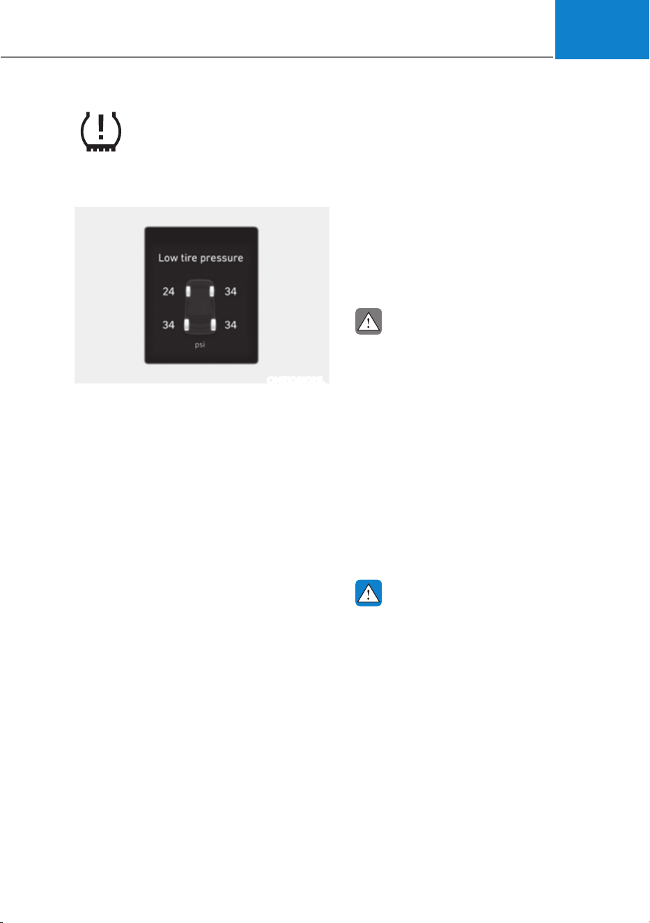
08
8-9
Low Tire Pressure
Warning Light
Low Tire Pressure Position and
Tire Pressure Telltale
ONE1081021L
When the tire pressure monitoring
system warning indicators are
illuminated and a warning message
displayed on the cluster LCD display,
one or more of your tires is significantly
under-inflated. The Low Tire Pressure
Position Telltale will indicate which
tire is significantly underinflated by
illuminating the corresponding position
light.
If either telltale illuminates, immediately
reduce your speed, avoid hard cornering
and anticipate increased stopping
distances. You should stop and check
your tires as soon as possible. Inflate the
tires to the proper pressure as indicated
on the vehicle’s placard or tire inflation
pressure label located on the driver’s
side center pillar outer panel.
If you cannot reach a service station or
if the tire cannot hold the newly added
air, replace the low pressure tire with the
spare tire.
The Low Tire Pressure Telltale will remain
on and the TPMS Malfunction Indicator
may blink for one minute and then
remain illuminated (when the vehicle
is driven approximately 10 minutes at
speed above 15.5 mph (25 km/h)) until
you have the low pressure tire repaired
and replaced on the vehicle.
CAUTION
In winter or cold weather, the Low Tire
Pressure Telltale may be illuminated if
the tire pressure was adjusted to the
recommended tire inflation pressure
in warm weather. It does not mean
your TPMS is malfunctioning because
the decreased temperature leads to a
proportional lowering of tire pressure.
When you drive your vehicle from a
warm area to a cold area or from a cold
area to a warm area, or the outside
temperature is greatly higher or lower,
you should check the tire inflation
pressure and adjust the tires to the
recommended tire inflation pressure.
WARNING
Low pressure damage
Significantly low tire pressure makes
the vehicle unstable and can contribute
to loss of vehicle control and increased
braking distances.
Continued driving on low pressure tires
can cause the tires to overheat and fail.

Emergency Situations
8-10
TPMS (Tire Pressure
Monitoring System)
Malfunction Indicator
The TPMS Malfunction Indicator
will illuminate after it blinks for
approximately one minute when there
is a problem with the Tire Pressure
Monitoring System.
Have the system checked by an
authorized HYUNDAI dealer as soon as
possible.
NOTICE
If there is a malfunction with the TPMS,
the Low Tire Pressure Position Telltale
will not be displayed even though the
vehicle has an under-inflated tire.
NOTICE
The TPMS Malfunction Indicator may
illuminate after blinking for one minute
if the vehicle is near electric power
supply cables or radio transmitters
such as police stations, government
and public offices, broadcasting
stations, military installations, airports,
transmitting towers, etc.
Additionally, the TPMS Malfunction
Indicator may illuminate if snow chains
are used or electronic devices such as
computers, chargers, remote starters,
navigation, etc. This may interfere with
normal operation of the TPMS.
Changing a Tire with TPMS
If you have a flat tire, the Low Tire
Pressure and Position telltales will come
on. Have the flat tire repaired by an
authorized HYUNDAI dealer as soon as
possible or replace the flat tire with the
spare tire.
NOTICE
It is recommended that you do not use a
puncture-repairing agent not approved
by an authorized HYUNDAI dealer or the
equivalent specified for your vehicle
to repair and/or inflate a low pressure
tire. Tire sealant not approved by an
authorized HYUNDAI dealer or the
equivalent specified for your vehicle
may damage the tire pressure sensor.
The spare tire (if equipped) does not
come with a tire pressure monitoring
sensor. When the low pressure tire or
the flat tire is replaced with the spare
tire, the Low Tire Pressure Telltale will
remain on. Also, the TPMS Malfunction
Indicator will illuminate after blinking
for one minute if the vehicle is driven
at speed above 15.5 mph (25 km/h) for
approximately 10 minutes.
Once the original wheel equipped with
a tire pressure monitoring sensor is
reinflated to the recommended pressure
and reinstalled on the vehicle, the
Low Tire Pressure Telltale and TPMS
Malfunction Indicator will go off within a
few minutes of driving.
If the indicators do not extinguish after
a few minutes, consult an authorized
HYUNDAI dealer.
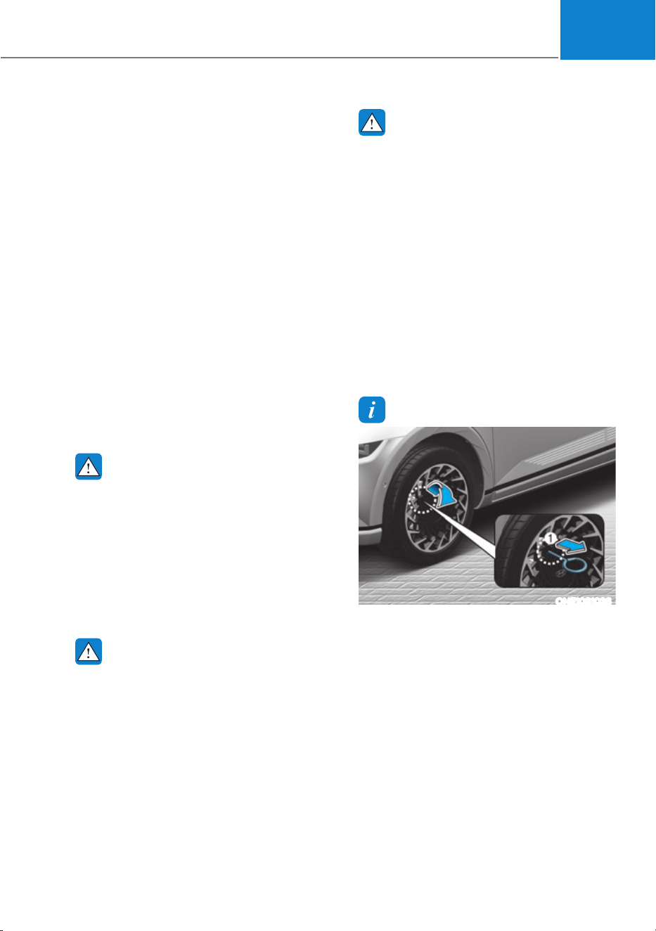
08
8-11
Each wheel is equipped with a tire
pressure sensor mounted inside the tire
behind the valve stem (except for the
spare tire). You must use TPMS specific
wheels. It is recommended that you
always have your tires serviced by an
authorized HYUNDAI dealer.
You may not be able to identify a tire
with low pressure by simply looking at it.
Always use a good quality tire pressure
gauge to measure. Please note that a tire
that is hot (from being driven) will have a
higher pressure measurement than a tire
that is cold.
A cold tire means the vehicle has been
sitting for 3 hours and driven for less
than 1 mile (1.6 km) in that 3 hour period.
Allow the tire to cool before measuring
the inflation pressure. Always be sure
the tire is cold before inflating to the
recommended pressure.
WARNING
ś The TPMS cannot alert you to severe
and sudden tire damage caused by
external factors such as nails or road
debris.
ś If you feel any vehicle instability,
immediately take your foot off
the accelerator, apply the brakes
gradually with light force, and slowly
move to a safe position off the road.
WARNING
Tampering with, modifying, or disabling
the Tire Pressure Monitoring System
(TPMS) components may interfere
with the system’s ability to warn the
driver of low tire pressure conditions
and/or TPMS malfunctions. Tampering
with, modifying, or disabling the Tire
Pressure Monitoring System (TPMS)
components may void the warranty for
that portion of the vehicle.
WARNING
This device complies with Part 15 of the
FCC rules.
Operation is subject to the following
three conditions:
1. This device may not cause harmful
interference.
2. This device must accept any
interference received, including
interference that may cause
undesired operation of the device.
3. Changes or modifications not
expressly approved by the party
responsible for compliance could
void the user’s authority to operate
the device.
Information
ONE1081026
For 20 inches wheel, take out the remover
tool (1) in the Tire Mobility Kit. Insert
the tool to the hole and pull out the wheel
cover.
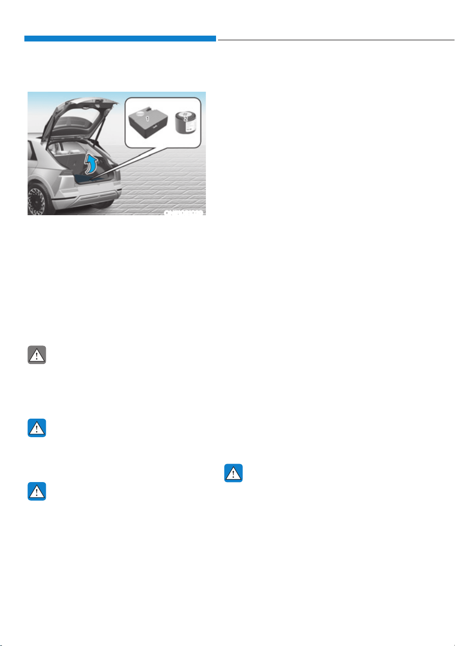
Emergency Situations
8-12
ONE1081029
For safe operation, carefully read and
follow the instructions in this manual
before use.
(1) Compressor
(2) Sealant bottle
The tire mobility kit is a temporary fix
to the tire, have the tire inspected by
an authorized HYUNDAI dealer or the
equivalent approved for your vehicle as
soon as possible.
CAUTION
When two or more tires are flat, do not
use the tire mobility kit because the
supported one sealant of Tire Mobility
Kit is only used for one flat tire.
WARNING
Do not use the Tire Mobility Kit to repair
punctures in the tire walls. This can
result in an accident due to tire failure.
WARNING
Have your tire repaired as soon as
possible. The tire may lose air pressure
at any time after inflating with the Tire
Mobility Kit.
Introduction
With the Tire Mobility Kit you stay mobile
even after experiencing a tire puncture.
The compressor and sealing compound
system effectively and comfortably seals
most punctures in a passenger car tire
caused by nails or similar objects and
reinflates the tire.
After you ensure that the tire is properly
sealed you can drive cautiously on the
tire (distance up to 120 miles (200 km))
at a max. speed of 50 mph (80 km/h) in
order to reach a service station or tire
dealer for the tire replacement.
It is possible that some tires, especially
with larger punctures or damage to the
sidewall, cannot be sealed completely.
Air pressure loss in the tire may adversely
affect tire performance.
For this reason, you should avoid abrupt
steering or other driving maneuvers,
especially if the vehicle is heavily loaded
or if a trailer is in use.
The Tire Mobility Kit is not designed
or intended as a permanent tire repair
method and is to be used for one tire
only.
This instruction shows you step by step
how to temporarily seal the puncture
simply and reliably.
Read the section “Notes on the safe use
of the Tire Mobility Kit”.
WARNING
Do not use the TMK if a tire is severely
damaged by driving run flat or with
insufficient air pressure.
Only punctured areas located within the
tread region of the tire can be sealed
using the TMK.
,)<28+$9($)/$77,5(ǣ:,7+7,5(02%,/,7<.,7
,)(48,33('Ǥ

08
8-13
Notes on the Safe Use of the Tire
Mobility Kit
ś Park your car at the side of the road
so that you can work with the Tire
Mobility Kit away from moving traffic.
ś To be sure your vehicle will not move,
even when you’re on fairly level
ground, always set your parking brake.
ś Only use the Tire Mobility Kit for
sealing/inflation passenger car tires.
Only punctured areas located within
the tread region of the tire can be
sealed using the tire mobility kit.
ś Do not use on motorcycles, bicycles
or any other type of tires.
ś When the tire and wheel are
damaged, do not use Tire Mobility Kit
for your safety.
ś Use of the Tire Mobility Kit may not be
effective for tire damage larger than
approximately 0.24 in (6 mm).
ś If the tire cannot be made roadworthy
with the Tire Mobility Kit, contact an
authorized HYUNDAI dealer.
ś Do not use the Tire Mobility Kit if a tire
is severely damaged by driving run flat
or with insufficient air pressure.
ś Do not remove any foreign objects
such as nails or screws that have
penetrated the tire.
ś Provided the car is outdoors, leave the
Vehicle is ON (
indicator ON).
Otherwise operating the compressor
may eventually drain the car battery.
ś Never leave the Tire Mobility Kit
unattended while it is being used.
ś Do not leave the compressor running
for more than 10 min. at a time or it
may overheat.
ś Do not use the Tire Mobility Kit if the
ambient temperature is below -22°F
(-30°C).
ś In case of skin contact with the
sealant, wash the area thoroughly
with plenty of water. If the irritation
persists, seek medical attention.
ś In case of eye contact with the
sealant, flush your eyes for at least 15
minutes. If the irritation persists, seek
medical attention.
ś In case of swallowing the sealant,
rinse the mouth and drink plenty of
water. However, never give anything
to an unconscious person and seek
medical attention immediately.
ś Long time exposure to the sealant
may cause damage to bodily tissue
such as kidney, etc.
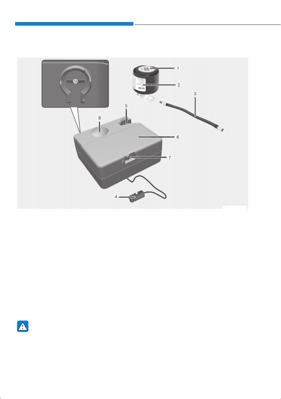
Emergency Situations
8-14
Components of the Tire Mobility Kit
ONE1081030
1. Speed-restriction label
2. Sealant bottle and label with speed restriction
3. Filling hose
4. Connectors and cable for the power outlet direct connection
5. Holder for the sealant bottle
6. Compressor
7. ON/OFF switch
8. Pressure gauge for displaying the tire inflation pressure
9. Button for reducing the tire inflation pressure
Connectors, cable and connection hose are stored in the compressor housing.
Strictly follow the specified sequence, otherwise the sealant may escape under high
pressure.
WARNING
Expired sealant
Do not use the Tire sealant after the sealant has expired (for example, the expiration
date on the sealant container). This can increase the risk of tire failure.
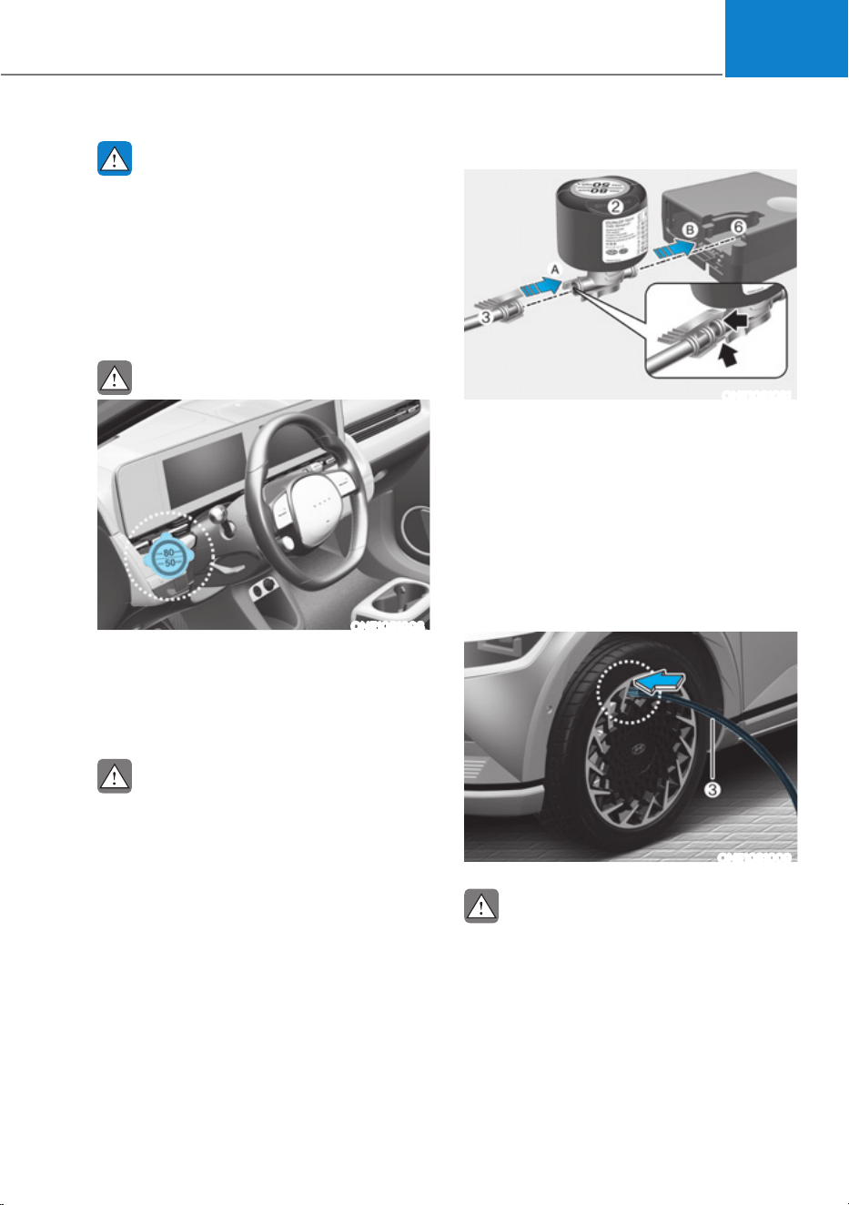
08
8-15
WARNING
Sealant
ś Keep out of reach of children.
ś Avoid contact with eyes.
ś Do not swallow.
Using the Tire Mobility Kit When
a Tire is Flat
CAUTION
ONE1081008
Detach the speed restriction label (1)
from the sealant bottle (2), and place
it in a highly visible place inside the
vehicle such as on the steering wheel to
remind the driver not to drive too fast.
CAUTION
If only the tire pressure needs to be
adjusted, refer to “How to Adjust Tire
Pressure” in this chapter.
Before using the Tire Mobility Kit, be
fully aware of the explanation on the
sealant.
1. Shake the sealant bottle (2).
ONE1081031
2. Connect the filling hose (3) to the
sealant bottle (2) in the direction of (A)
and connect the sealant bottle to the
compressor (6) in the direction of (B).
3. Ensure that the compressor is
switched OFF.
4. Unscrew the valve cap from the valve
of the defective wheel and screw the
filling hose (3) of the sealant bottle
onto the valve.
ONE1081009
CAUTION
Securely install the sealant filling hose
to the valve. If not, sealant may flow
backward, possibly clogging the filling
hose.
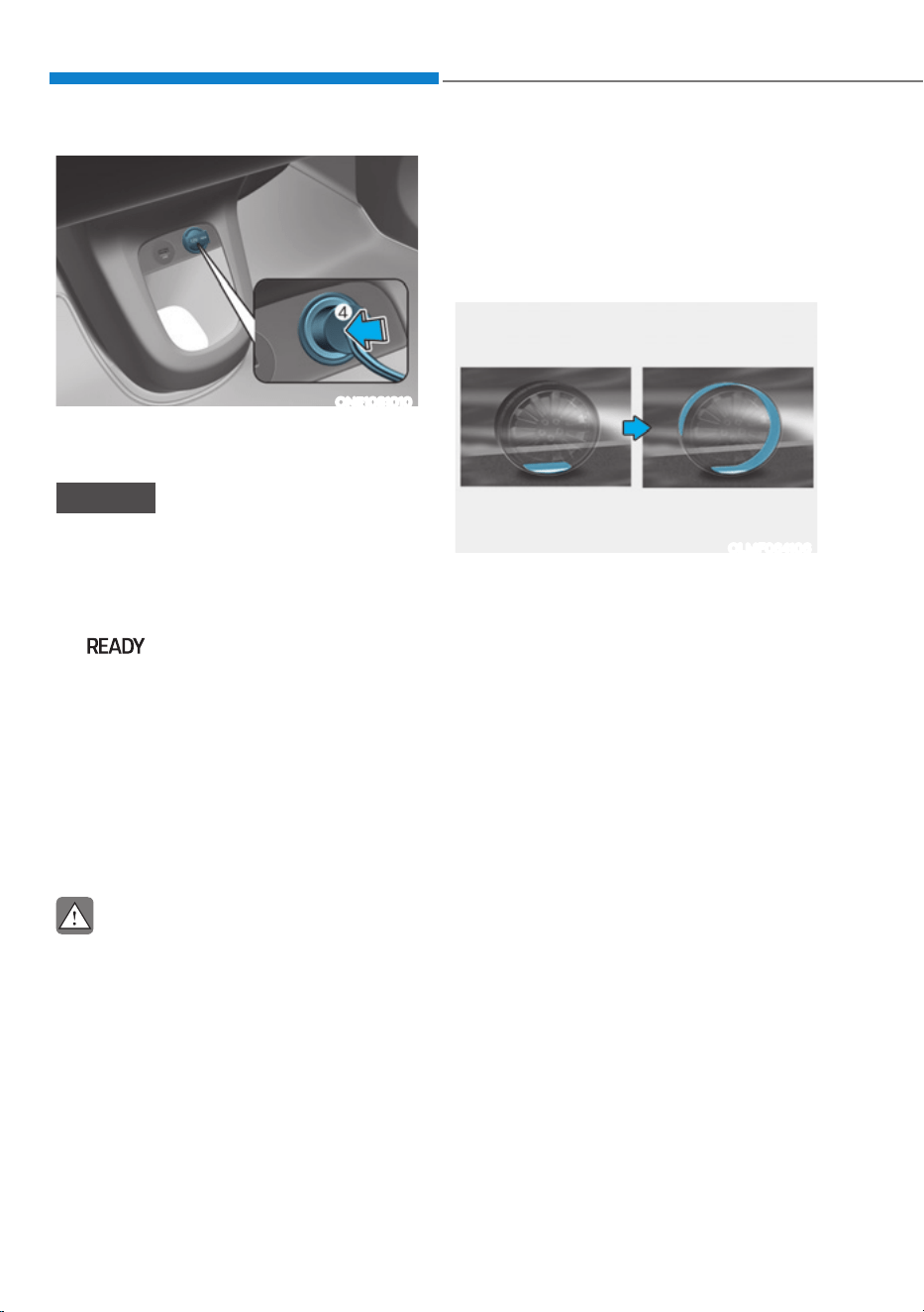
Emergency Situations
8-16
ONE1081010
5. Plug the compressor power cord (4)
into the vehicle power outlet.
NOTICE
Only use the front passenger side
power outlet when connecting the
power cord.
6. With the vehicle ON
(
indicator ON), switch on
the compressor and let it run for
approximately 5~7 minutes to fill the
sealant up to proper pressure. (refer
to the Tire and Wheels, chapter 2).
The inflation pressure of the tire after
filling is unimportant and will be
checked/corrected later.
Be careful not to overinflate the tire
and stay away from the tire when
filling it.
CAUTION
Tire pressure
Do not attempt to drive your vehicle if
the tire pressure is below 200 kPa (29
psi). This could result in an accident due
to sudden tire failure.
7. Switch off the compressor.
8. Detach the hoses from the sealant
bottle connector and from the tire
valve.
Return the Tire Mobility Kit to its storage
location in the vehicle.
OLMF064106
9. Immediately drive approximately 4~6
miles (7~10 km or, about 10min) to
evenly distribute the sealant in the
tire.
Do not exceed a speed of 50 mph (80
km/h). If possible, do not fall below a
speed of 12 mph (20 km/h).
While driving, if you experience any
unusual vibration, ride disturbance or
noise, reduce your speed and drive with
caution until you can safely pull off of the
side of the road.
Call for road side service or towing.
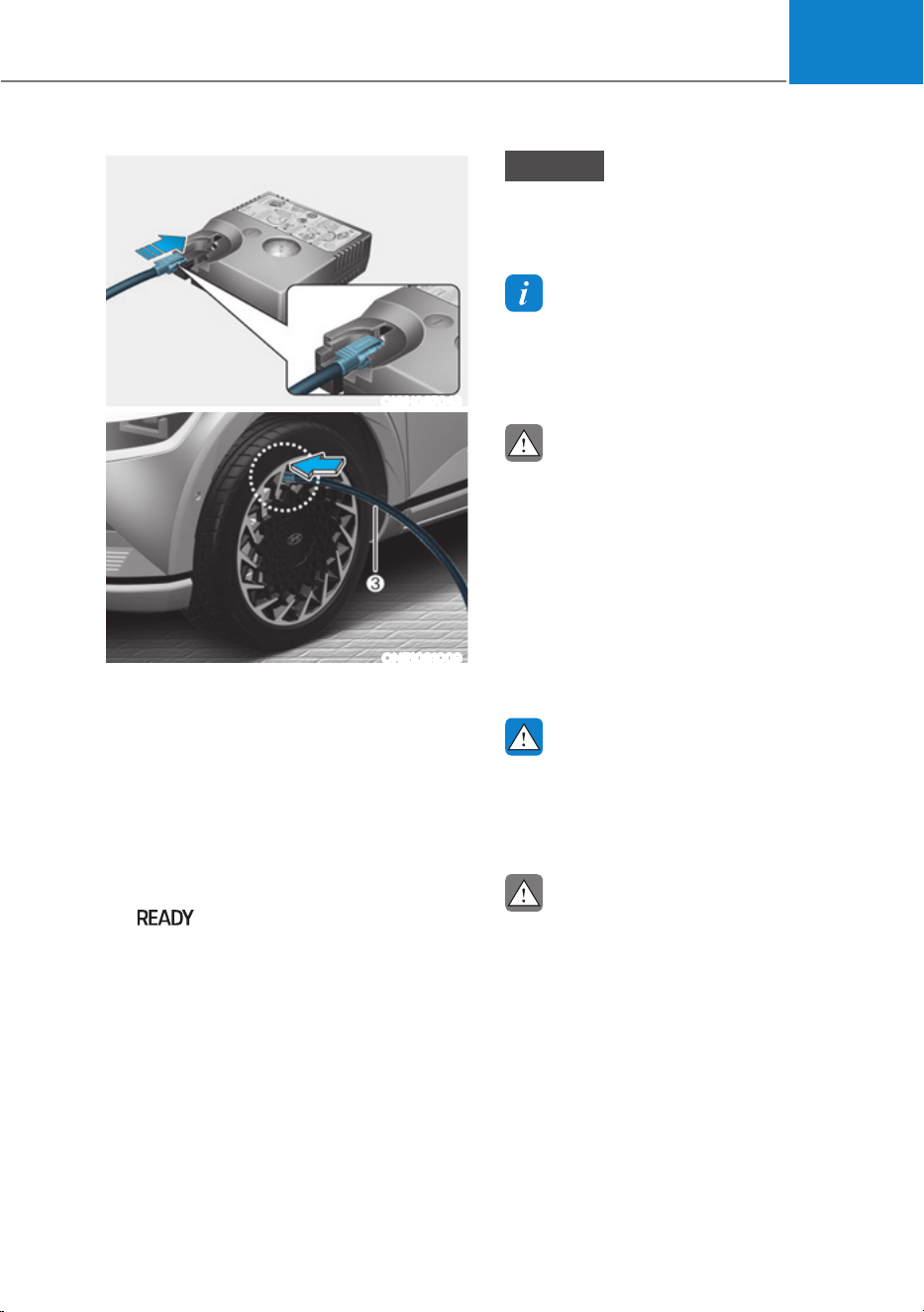
08
8-17
OIGH067043
ONE1081009
10.
After driving approximately 4~6 miles
(7~10 km or about 10 min), stop at a
safety location.
11.
Connect the filling hose (3) of the
compressor directly to the tire valve.
12.
Plug the compressor power cord into
the vehicle power outlet.
13.
Adjust the tire inflation pressure to the
recomended tire inflation.
With the Vehicle is ON
(
indicator ON) proceed as
follows.
- To increase the inflation pressure
: Switch on the compressor. To
check the current inflation pressure
setting, briefly switch off the
compressor.
- To reduce the inflation pressure:
Press the button (9) on the
compressor.
-
NOTICE
Do not let the compressor run for more
than 10 minutes, otherwise the device
will overheat and may be damaged.
Information
The pressure gauge may show higher than
actual reading when the compressor is
running. To get an accurate tire reading,
the compressor needs to be turned off.
CAUTION
If the inflation pressure is not
maintained, drive the vehicle a second
time, refer to step 9.
Then repeat steps 10 to 13.
Use of the TMK may be ineffectual for
tire damage larger than approximately
0.16 in (4 mm).
Contact an authorized HYUNDAI dealer
if the tire cannot be made roadworthy
with the Tire Mobility Kit.
WARNING
The tire inflation pressure must be at
least 32 psi (220 kPa). If it is not, do not
continue driving.
Call for road side service or towing.
CAUTION
Tire pressure sensor (if equipped with
TPMS)
The sealant on the tire pressure sensor
and wheel should be removed when
you replace the tire with a new one and
inspect the tire pressure sensors. We
recommend that you get this done at an
authorized HYUNDAI dealer.
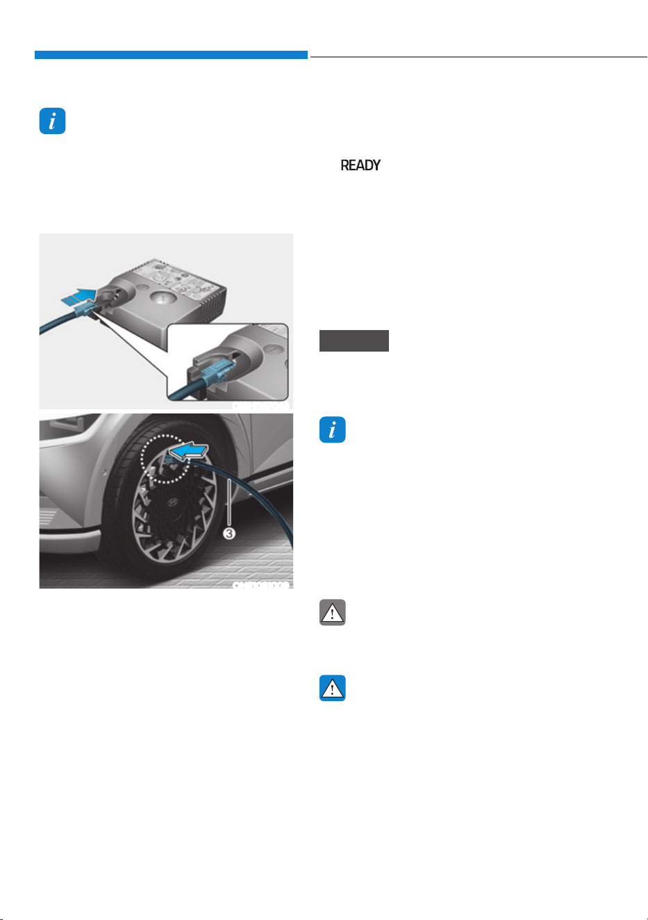
Emergency Situations
8-18
Information
When reinstalling the repaired or
replaced tire and wheel on the vehicle,
tighten the wheel lug nut to 79~94 lbf·ft
(11~13 kgf·m).
How to Adjust Tire Pressure
OIGH067043
ONE1081009
1. Park your vehicle in a safe location.
2. Connect the filling hose (3) of the
compressor directly to the tire valve.
3. Plug the compressor power cord into
the vehicle power outlet.
4. Adjust the tire inflation pressure to the
recomended tire inflation.
With the Vehicle is ON
(
indicator ON), proceed as
follows.
- To increase the inflation pressure
: Switch on the compressor. To
check the current inflation pressure
setting, briefly switch off the
compressor.
- To reduce the inflation pressure:
Press the button (9) on the
compressor.
NOTICE
Do not let the compressor run for more
than 10 minutes, otherwise the device
will overheat and may be damaged.
Information
ś The pressure gauge may show
higher than actual reading when the
compressor is running. To get an
accurate tire reading, the compressor
needs to be turned off.
ś When reinstalling the repaired or
replaced tire and wheel on the vehicle,
tighten the wheel lug nut to 79~94 lbf·ft
(11~13kgf·m).
CAUTION
Do not use the sealant when the tire
pressure only needs to be adjusted.
WARNING
The tire inflation pressure must be at
least 220 kPa (32 psi). If it is not, do not
continue driving.
Call for road side service or towing.
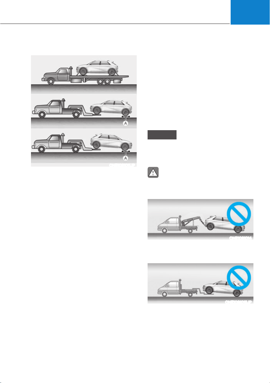
08
8-19
Towing Service
ONE1081011JP
[A] : Dollies
If emergency towing is necessary, have it
done by an authorized HYUNDAI dealer
or a commercial tow-truck service.
Proper lifting and towing procedures
are necessary to prevent damage to
the vehicle. The use of wheel dollies or
flatbed is recommended.
For 2WD vehicles, it is acceptable to tow
the vehicle with the front wheels on the
ground (without dollies) and the rear
wheels off the ground.
If any of the loaded wheels or suspension
components are damaged or the vehicle
is being towed with the rear wheels on
the ground, use a towing dolly under the
rear wheels.
When being towed by a commercial tow
truck and wheel dollies are not used,
the rear of the vehicle should always be
lifted, not the front.
For AWD vehicles, it must be towed
with a wheel lift and dollies or flatbed
equipment with all the wheels off the
ground.
Precautions when moving a short
distance before towing a vehicle
Move short distances within 394 in. (10
m) at a speed of 3 mph (5 km/h) or less
only when loading on a tow truck or if
the vehicle needs to be repositioned.
At this time, the gear must be in the ‘N’
(neutral) position and the parking brake
must be released. If it is impossible to
operate the transmission and parking
brake, move the vehicle with the rear
wheel lifted.
NOTICE
Do not lift the vehicle by the tow fitting
or body and chassis parts. Otherwise
the vehicle may be damaged.
CAUTION
ś Do not tow the vehicle with the rear
wheels on the ground as this may
cause damage to the vehicle.
ONE1081014
ś Do not tow with sling-type
equipment. Use wheel lift or flatbed
equipment.
ONE1081015JP
When towing your vehicle in an
emergency without wheel dollies:
1. While depressing the brake pedal
shift to the N (Neutral) position and
turn the vehicle off. The START/STOP
button will be in the ACC position.
2. Release the parking brake.
TOWING
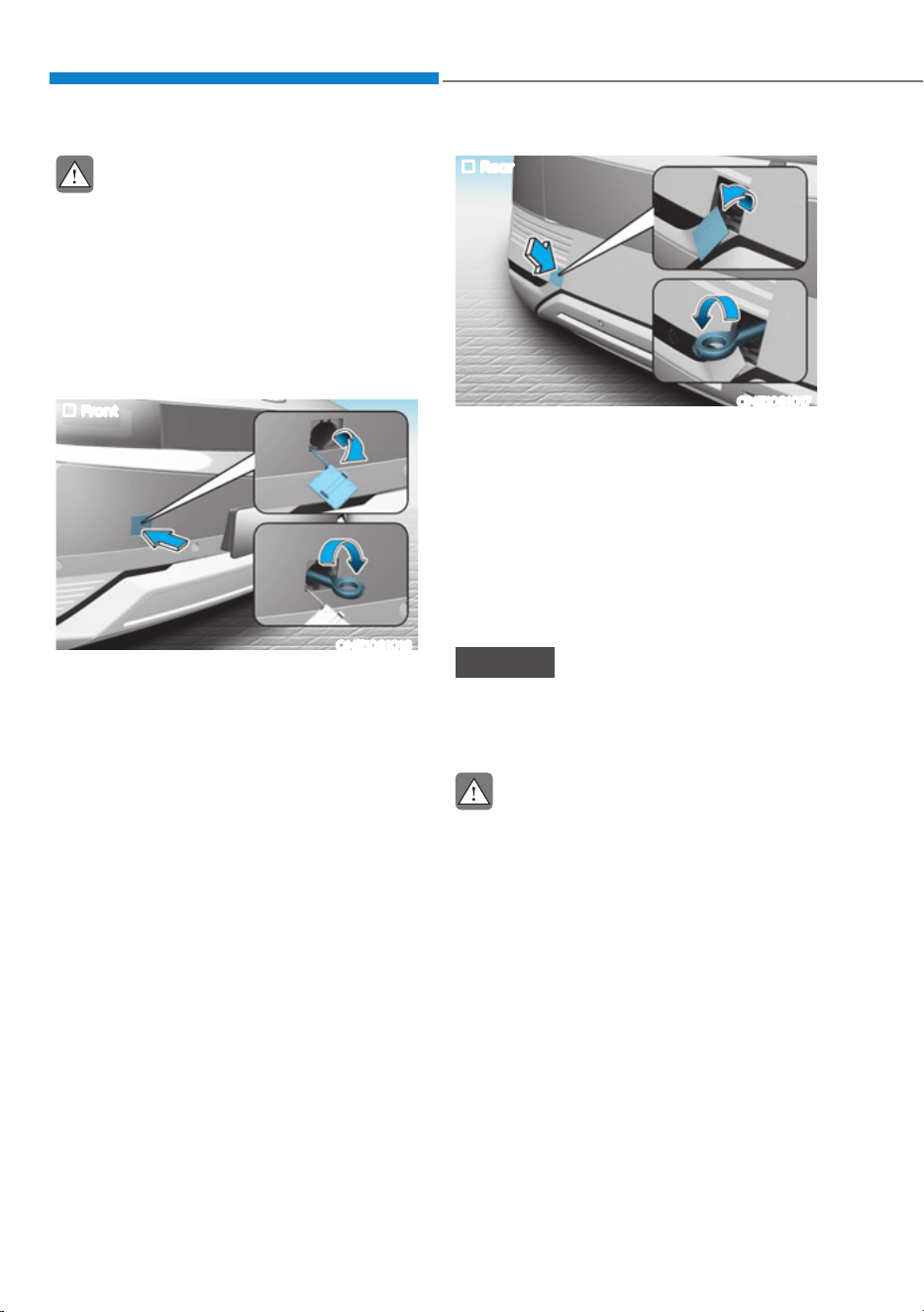
Emergency Situations
8-20
CAUTION
Failure to shift the gear to N (Neutral)
may cause internal damage to the
reduction gear.
Removable Towing Hook
1. Open the liftgate, and remove the
towing hook from the tool case.
2. Remove the hole cover.
Front
ONE1081016
ś Push the lower part of the bumper
hole cover.
Rear
ONE1081017
ś Push the upper part of the bumper
hole cover.
ś Pull the lower part of the bumper hole
cover.
3. Install the towing hook by turning it
clockwise into the hole until it is fully
secured.
4. Remove the towing hook and install
the cover after use.
NOTICE
Failure to properly tighten the towing
hook may result in vehicle damage and
deformation of related parts.
CAUTION
Make sure the towing hook is tighten
properly. If not, during towing the
towing hook may be thrown off the
vehicle resulting in serious injury or
accident.

9
9. Maintenance
Motor Compartment ........................................................................................ 9-3
Maintenance Services ...................................................................................... 9-4
Owner’s Responsibility ............................................................................................... 9-4
Owner Maintenance Precautions ............................................................................... 9-4
Owner Maintenance ......................................................................................... 9-5
Owner Maintenance Schedule ................................................................................... 9-6
Scheduled Maintenance Services ....................................................................9-7
Normal Maintenance Schedule ................................................................................. 9-8
Normal Maintenance Schedule .................................................................................. 9-9
Maintenance Under Severe Usage Conditions ........................................................ 9-10
Explanation of Scheduled Maintenance Items ...............................................9-11
Coolant .............................................................................................................9-12
Brake Fluid ........................................................................................................9-13
Checking the Brake Fluid Level ................................................................................. 9-13
Reduction Gear Fluid .......................................................................................9-14
Washer Fluid .....................................................................................................9-14
Checking the Washer Fluid Level .............................................................................. 9-14
Cabin Air Filter ..................................................................................................9-15
Filter Inspection.......................................................................................................... 9-15
Filter Replacement ..................................................................................................... 9-15
Wiper Blades ....................................................................................................9-16
Blade Inspection ........................................................................................................ 9-16
Blade Replacement .................................................................................................... 9-16
Battery (12 volt) ................................................................................................9-19
For best battery service ............................................................................................ 9-20
Battery Capacity Label .............................................................................................. 9-20
Battery Recharging ................................................................................................... 9-20
Reset Items ................................................................................................................. 9-21

9
Tires and Wheels ............................................................................................. 9-22
Tire Care ......................................................................................................................9-22
Recommended Cold Tire Inflation Pressures ...........................................................9-22
Check Tire Inflation Pressure .....................................................................................9-23
Tire Rotation ...............................................................................................................9-24
Wheel Alignment and Tire Balance ...........................................................................9-25
Tire Replacement .......................................................................................................9-25
Wheel Replacement ...................................................................................................9-26
Tire Traction ................................................................................................................9-26
Tire Maintenance........................................................................................................9-26
Tire Sidewall Labeling ................................................................................................9-26
Tire Terminology and Definitions ..............................................................................9-29
All Season Tires ...........................................................................................................9-33
Summer Tires .............................................................................................................9-33
Snow Tires...................................................................................................................9-33
Radial-Ply Tires ...........................................................................................................9-33
Low Aspect Ratio Tires ...............................................................................................9-34
Fuses ................................................................................................................ 9-35
Instrument Panel Fuse Replacement ........................................................................9-36
Motor Compartment Panel Fuse Replacement .......................................................9-37
Fuse/Relay Panel Description................................................................................... 9-38
Light Bulbs .......................................................................................................9-48
Headlamp, Parking Lamp, Turn Signal Lamp, Daytime Running Light (DRL)
Replacement ............................................................................................................. 9-49
Side Repeater Lamp Replacement ........................................................................... 9-51
Rear Combination Lamp Replacement .................................................................... 9-51
High Mounted Stop Lamp Replacement ..................................................................9-53
License Plate Lamp Replacement .............................................................................9-53
Front Trunk Lamp Replacement ............................................................................... 9-54
Interior Light Replacement ....................................................................................... 9-54
Appearance care .............................................................................................9-56
Exterior Care .............................................................................................................. 9-56
Interior Care ................................................................................................................ 9-61
California Perchlorate Notice .........................................................................9-64

9-3
09
The actual motor compartment in the vehicle may differ from the illustration.
ONE1091001
1. Coolant reservoir
2. Low Conductivity Water (LCW)
coolant reservoir
3. Brake fluid reservoir
4. Windshield washer fluid reservoir
5. Fuse box
6. Climate control system air filter
7. Front trunk
8. Battery (12V)
MOTOR COMPARTMENT

Maintenance
9-4
You should exercise the utmost care
to prevent damage to your vehicle and
injury to yourself whenever performing
any maintenance or inspection
procedures.
Have your vehicle maintained and
repaired by an authorized HYUNDAI
dealer. An authorized HYUNDAI dealer
meets HYUNDAI’s high service quality
standards and receives technical support
from HYUNDAI in order to provide you
with a high level of service satisfaction.
Owner’s Responsibility
Maintenance service and record
retention are the owner’s responsibility.
You should retain documents that show
proper maintenance has been performed
on your vehicle in accordance with
the scheduled maintenance service
charts shown on the following pages.
You need this information to establish
your compliance with the servicing
and maintenance requirements of your
vehicle warranties.
Detailed warranty information is
provided in your Owner’s Handbook &
Warranty Information booklet.
Repairs and adjustments required as a
result of improper maintenance or a lack
of required maintenance are not covered.
Owner Maintenance Precautions
Inadequate, incomplete or insufficient
servicing may result in operational
problems with your vehicle that could
lead to vehicle damage, an accident, or
personal injury. This chapter provides
instructions only for the maintenance
items that are easy to perform.
Your vehicle should not be modified
in any way. Such modifications may
adversely affect the performance, safety
or durability of your vehicle and may, in
addition, violate conditions of the limited
warranties covering the vehicle.
Certain modifications may also be in
violation of regulations established by
the U.S. Department of Transportation
and other federal or state agencies.
NOTICE
Improper owner maintenance during
the warranty period may affect
warranty coverage. For details, read
the separate Owner’s Handbook &
Warranty Information booklet provided
with the vehicle. If you’re unsure about
any service or maintenance procedure,
have it done by an authorized HYUNDAI
dealer.
MAINTENANCE SERVICES

09
9-5
WARNING
Performing maintenance work on a
vehicle can be dangerous. If you lack
sufficient knowledge and experience
or the proper tools and equipment to
do the work, we recommend that it is
done by an authorized HYUNDAI dealer.
ALWAYS follow these precautions for
performing maintenance work:
ś Park your vehicle on level ground.
Shift the vehicle to P (Park), apply the
parking brake, and press the Start/
Stop button to the OFF position.
ś Block the tires (front and back) to
prevent the vehicle from moving.
Remove loose clothing or jewelry
that can become entangled in
moving parts.
ś Keep flames, sparks, or smoking
materials away from the battery and
motor related parts.
WARNING
Make sure to turn the START/STOP
button to the ‘OFF’ position to shut
down the vehicle before performing
maintenance work on the vehicle.
The following lists are vehicle checks and
inspections that should be performed
by the owner or an authorized HYUNDAI
dealer at the frequencies indicated to
help ensure safe, dependable operation
of your vehicle.
Any adverse conditions should be
brought to the attention of your dealer as
soon as possible.
These Owner Maintenance vehicle
checks are generally not covered by
warranties and you may be charged for
labor, parts and lubricants used.
The electric control system in the vehicle
may cause malfunction or other negative
impact on the artificial heart and the
artificial internal organs. Be sure to
inquire the impact of the electric control
system on the artificial organs from the
medical product corporation.
OWNER MAINTENANCE

Maintenance
9-6
Owner Maintenance Schedule
When you stop for charging:
ś Check the coolant level in the coolant
reservoir.
ś Check the windshield washer fluid
level.
ś Check for low or under-inflated tires.
WARNING
Be careful when checking your coolant
level if the motor compartment is hot.
This may result in coolant being blown
out of the opening and cause serious
burns and other injuries.
While operating your vehicle:
ś Check for vibrations in the steering
wheel. Notice if there is any increased
steering effort or looseness in the
steering wheel, or change in its
straight-ahead position.
ś Notice if your vehicle constantly turns
slightly or “pulls” to one side when
traveling on smooth, level road.
ś When stopping, listen and check for
unusual sounds, pulling to one side,
increased brake pedal travel or “hard-
to-push” brake pedal.
ś If any slipping or changes in the
operation of your gear shift occurs,
check the shift gear fluid level.
ś Check the shift gear P (Park) function.
ś Check the parking brake.
ś Check for fluid leaks under your
vehicle (water dripping from the air
conditioning system during or after
use is normal).
At least monthly:
ś Check coolant level in the coolant
reservoir.
ś Check the operation of all exterior
lights, including the stoplights, turn
signals and hazard warning flashers.
ś Check the inflation pressures of all
tires including the spare for tires that
are worn, show uneven wear, or are
damaged.
ś Check for loose wheel lug nuts.
At least twice a year: (for example,
every Spring and Autumn)
ś Check radiator, heater and air
conditioning hoses for leaks or
damage.
ś Check windshield washer spray and
wiper operation. Clean wiper blades
with a clean cloth dampened with
washer fluid.
ś Check headlamp alignment.
ś Check the seat belts for wear and
function.
At least once a year:
ś Clean body and door drain holes.
ś Lubricate door hinges and hood
hinges.
ś Lubricate door and hood locks and
latches.
ś Lubricate door rubber weather strips.
ś Check the air conditioning system.
ś Inspect and lubricate shift gear
linkage and controls.
ś Clean the battery (12V) and terminals.
ś Check the brake fluid level.

09
9-7
Follow Normal Maintenance Schedule if the vehicle is usually operated where none of
the following conditions apply. If any of the following conditions apply, you must follow
the Maintenance Under Severe Usage Conditions.
ś Repeated driving short distance of less than 5 miles (8 km) in normal temperature or
less than 10 miles (16 km) in freezing temperature
ś Driving on rough, dusty, muddy, unpaved, graveled or salt-spread roads
ś Driving in areas using salt or other corrosive materials or in very cold weather
ś Driving in heavy dust conditions
ś Driving in heavy traffic area
ś Driving in heavy traffic area with the ambient temperature higher than 32 ºC (90 ºF)
while consuming more than 50% of electric energy.
ś Towing a trailer or using a camper, or driving with loads on the roof
ś Driving as a patrol car, taxi, other commercial use of vehicle towing
ś Frequently driving under high speed or rapid acceleration/deceleration
ś Frequently driving in stop-and-go condition
If your vehicle is operated under the above conditions, you should inspect, replace
or refill more frequently than the following Normal Maintenance Schedule. After the
periods or distance shown in the chart, continue to follow the prescribed maintenance
intervals.
NOTICE
After driving more than 10 years or 100,000 miles, use severe maintenance schedule.
SCHEDULED MAINTENANCE SERVICES
9-8
Maintenance
Normal Maintenance Schedule
The following maintenance services must be performed to ensure good vehicle performance.
Keep receipts for all vehicle services to protect your warranty. Where both mileage and time are shown, the frequency of
service is determined by whichever occurs first.
MAINTENANCE
INTERVALS
MAINTENANCE
ITEM
Months
4 8 12 16 20 24 28 32 36 40 44 48 52 56 60 64 68 72 76 80 84 88 92 96
Miles×1,000
5 10 15 20 25 30 35 40 45 50 55 60 65 70 75 80 85 90 95 100 105 110 115 120
Km×1,000
8 16 24 32 40 48 56 64 75 80 88 96 104 112 120 128 136 144 152 160 168 176 184 192
Cooling system Inspect every 15,000 miles or 12 months
Rotate Tires
(Includes Tire Pressure and
Tread Wear Inspection)
Rotate every 5,000 miles (8,000 km)
Replace Climate Control Air
Filter (For Evaporator and
Blower Unit)
RR
RRRRRR
Coolant *
1
Standard
At first, replace 120,000 miles (200,000 km) or 120 months.
After that, replace every 25,000 miles (40,000 km) or 24 month.
Low
Conductivity
Replace every 35,000 miles (60,000 km) or 36 months *
2
12V auxiliary battery condition I I
IIIIII
Brake lines, hoses, and connections I I
IIIIII
I : Inspect and if necessary, adjust, correct, clean or replace.
R : Replace or change.
*1 :
When replacing or adding coolant, visit an authorized HYUNDAI dealer.
*2 :
For your convenience, it can be replaced prior to it’s interval when you do maintenance of other items.

9-9
09
Normal Maintenance Schedule
MAINTENANCE
INTERVALS
MAINTENANCE
ITEM
Months
4 8 12 16 20 24 28 32 36 40 44 48 52 56 60 64 68 72 76 80 84 88 92 96
Miles×1,000
5 10 15 20 25 30 35 40 45 50 55 60 65 70 75 80 85 90 95 100 105 110 115 120
Km×1,000
8 16 24 32 40 48 56 64 75 80 88 96 104 112 120 128 136 144 152 160 168 176 184 192
Disc brakes and pads I I
IIIIII
Steering gear rack,
linkage, and boots
II
IIIIII
Drive shafts and boots I I
IIIIII
Air conditioning
compressor, air conditioner
refrigerant and performance
II
IIIIII
Reduction gear fluid I I I
Brake pedal I I
IIIIII
Brake fluid
Inspect every 5,000 miles (8,000 km) or 12 months,
Replace every 60,000 miles (96,000 km) or 48 months
I : Inspect and if necessary, adjust, correct, clean or replace.
R : Replace or change.

Maintenance
9-10
Maintenance Under Severe Usage and Low Mileage Conditions
The following items must be serviced more frequently on cars mainly used under
severe driving conditions.
Refer to the chart below for the appropriate maintenance intervals.
R : Replace I : Inspect and if necessary, adjust, correct, clean or replace
Maintenance item
Maintenance
operation
Maintenance intervals
Driving
condition
Reduction gear fluid
R
Every 80,000 miles
(120,000 km)
C, D, E, F, G,
H, I, J
Steering gear rack,
linkage and boots
I
Inspect more frequently
depending on the condition
C, D, E, F, G
Front suspension ball
joints
I
Inspect more frequently
depending on the condition
C, D, E, F, G
Disc brakes and pads,
calipers and rotors
I
Inspect more frequently
depending on the condition
C, D, E, G, H
Driveshaft and boots
I
Inspect more frequently
depending on the condition
C, D, E, F,
G, H, I , J
Climate control air filter
R
Replace more frequently
depending on the condition
C, E, G
Severe driving conditions
A. Repeatedly driving short distance of less than 5 miles (8 km) in normal temperature
or less than 10 miles (16 km) in freezing temperature
B. Low speed driving for long distances
C. Driving on rough, dusty, muddy, unpaved, graveled or salt spread roads
D. Driving in areas using salt or other corrosive materials or in very cold weather
E. Driving in heavy dust condition
F. Driving in heavy traffic area
G. Driving on uphill, downhill, or mountain roads repeatedly
H. Towing a trailer, or using a camper or roof rack
I. Driving as a patrol car, taxi, other commercial use or vehicle towing
J. Driving over 106 mph (170 km/h)
K. Frequently driving in stop-and-go conditions

09
9-11
Cooling System
Check cooling system components, such
as radiator, coolant reservoir, hoses and
connections for leakage and damage.
Replace any damaged parts.
Coolant
The coolant should be changed at the
intervals specified in the maintenance
schedule.
Reduction Gear Fluid
The reduction gear fluid should be
inspected according to the intervals
specified in the maintenance schedule.
Brake Hoses and Lines
Visually check for proper installation,
chafing, cracks, deterioration and any
leakage. Replace any deteriorated or
damaged parts immediately.
Brake Fluid
Check the brake fluid level in the brake
fluid reservoir. The level should be
between the MIN and the MAX marks
on the side of the reservoir. Use only
hydraulic brake fluid conforming to DOT
4 specification.
Brake Discs, Pads, Calipers and
Rotors
Check the pads, the disc, and the rotor
for any excessive wear-out. Inspect
calipers for any fluid leakage.
Suspension Mounting Bolts
Check the suspension connections for
looseness or damage. Retighten to the
specified torque.
Steering Gear Box, Linkage &
Boots/Lower Arm Ball Joint
With the vehicle stopped and the vehicle
off, check for excessive free-play in the
steering wheel. Check the linkage for
bends or damage. Check the dust boots
and ball joints for deterioration, cracks,
or damage.
Replace any damaged parts.
Drive Shafts and Boots
Check the drive shafts, boots and clamps
for cracks, deterioration, or damage.
Replace any damaged parts and, if
necessary, repack the grease.
Air Conditioning Refrigerant
Check the air conditioning lines and
connections for leakage and damage.
EXPLANATION OF SCHEDULED MAINTENANCE ITEMS
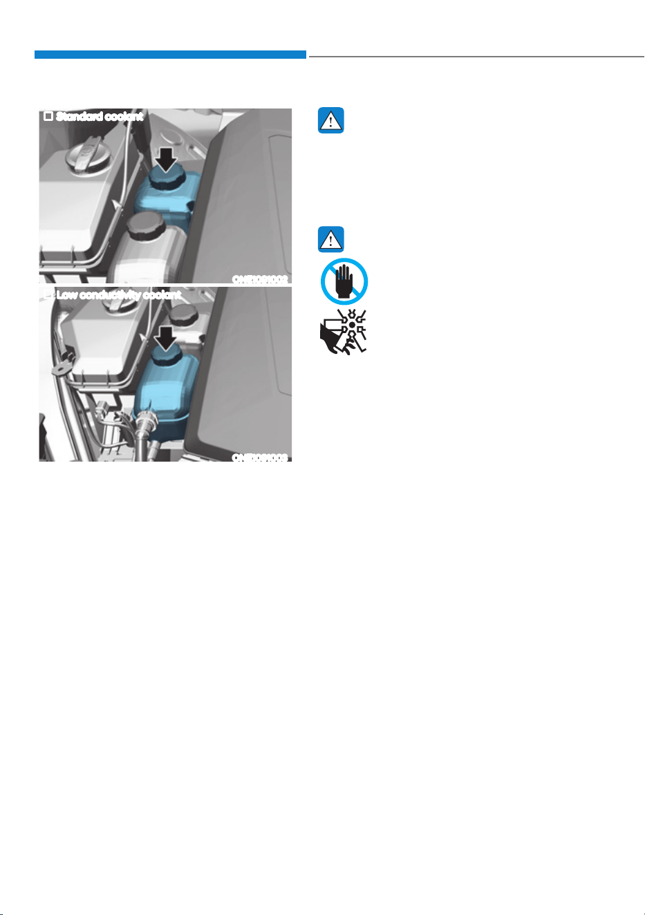
Maintenance
9-12
Standard coolant
ONE1091002
Low conductivity coolant
ONE1091003
Check the condition and connections
of all cooling system hoses and
heater hoses. Replace any swollen or
deteriorated hoses.
The coolant level should be filled
between the MAX or F and the MIN
or L marks on the side of the coolant
reservoir when the parts in the motor
compartment is cool.
If the coolant is low, have the vehicle
inspected by an authorized HYUNDAI
dealer.
Use only designated coolant water for
electric vehicles, adding other types
of water or antifreeze can damage the
vehicle.
WARNING
Since specific coolant water (Blue color,
Low conductivity) is applied for electric
vehicles, replenishment of other
antifreeze or water may cause problems
to the vehicle.
WARNING
The electric motor for the
cooling fan may continue to
operate or start up when the
vehicle is not running and can
cause serious injury.
Keep hands, clothing and tools
away from the rotating fan
blades of the cooling fan.
The electric motor for the cooling
fan is controlled by vehicle coolant
temperature, refrigerant pressure and
vehicle speed. As the vehicle coolant
temperature decreases, the electric
motor will automatically shut off. This is
a normal condition.
COOLANT
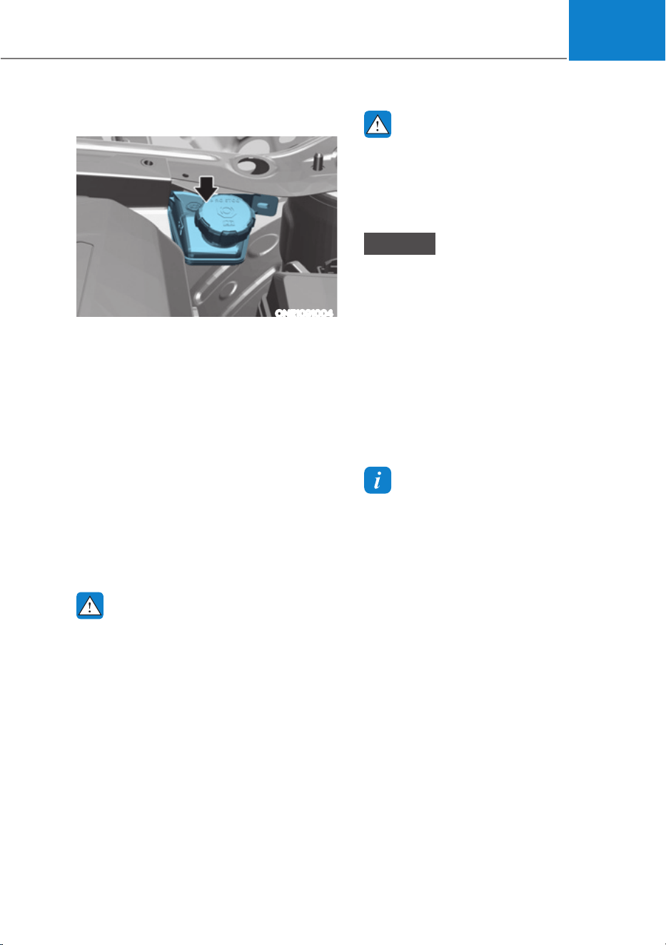
09
9-13
Checking the Brake Fluid Level
ONE1091004
Check the fluid level in the reservoir
periodically. The fluid level should be
between MAX and MIN marks on the side
of the reservoir.
Before removing the reservoir cap and
adding brake fluid, clean the area around
the reservoir cap thoroughly to prevent
brake fluid contamination.
If the level is low, add the specified brake
fluid to the MAX level. The level will fall
with accumulated kilometers. This is a
normal condition associated with the
wear of the brake linings. If the fluid level
is excessively low, have the brake system
checked by an authorized HYUNDAI
dealer.
WARNING
If the brake system requires frequent
additions of fluid this could indicate
a leak in the brake system. Have the
vehicle inspected by an authorized
HYUNDAI dealer.
WARNING
Do not let brake fluid enter into your
eyes. If brake fluid gets in your eyes,
flush your eyes with clean water for
at least 15 minutes and get immediate
medical attention.
NOTICE
ś Do not allow brake fluid to contact
the vehicle’s body paint, as it will
result in paint damage.
ś NEVER use brake fluid which has
been exposed to open air for an
extended time, as its quality cannot
be guaranteed. It should be disposed
of properly.
ś Do not use the wrong type of brake
fluid. A few drops of mineral based
oil in your brake system can damage
brake system parts.
Information
Use only the specified brake fluid (refer
to “Recommended Lubricants and
Capacities” section in chapter 2).
BRAKE FLUID
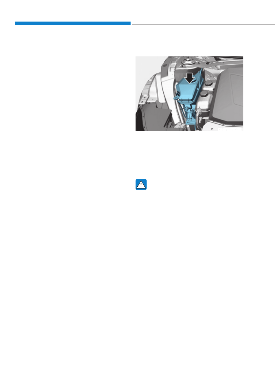
Maintenance
9-14
Checking the Washer Fluid Level
ONE1091005
Check the fluid level in the washer fluid
reservoir and add fluid if necessary. Plain
water may be used if washer fluid is not
available. However, use washer solvent
with antifreeze characteristics in cold
climates to prevent freezing.
WARNING
To prevent serious injury or death, take
the following safety precautions when
using washer fluid:
ś Do not use coolant or antifreeze in
the washer fluid reservoir. Coolant
can severely obscure visibility when
sprayed on the windshield and
may cause loss of vehicle control
resulting in an accident or damage to
paint and body trim.
ś Do not allow sparks or flame to
contact the washer fluid or the
washer fluid reservoir. Washer fluid
may contain alcohol and can be
flammable.
ś Do not drink washer fluid and avoid
contact with skin. Washer fluid is
harmful to humans and animals.
ś Keep washer fluid away from
children and animals.
WASHER FLUIDREDUCTION GEAR FLUID
There is no reduction gear fluid level
gauge in the vehicle. Check the
reduction gear fluid every 60,000 km
regularly. If the vehicle is driven under
severe condition, check the maintenance
under severe usage condition and
consult an authorized HYUNDAI dealer.
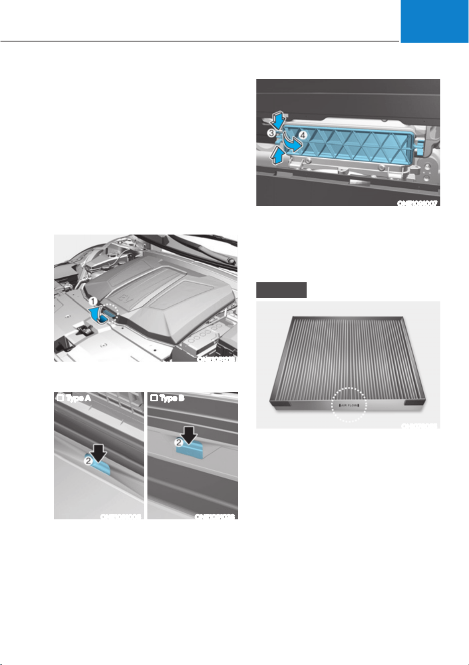
09
9-15
Filter Inspection
The cabin air filter should be replaced
according to the Maintenance Schedule.
If the vehicle is operated in severely air-
polluted cities or on dusty rough roads
for a long period, it should be inspected
more frequently and replaced sooner.
Replace the cabin air filter by following
the procedure below and be careful to
avoid damaging other components.
Filter Replacement
1. Open the hood.
ONE1051213
2. Lift up the front trunk cover while
depressing the front trunk lever (1).
Type A Type B
ONE1091006 ONE1091033
3. Remove the cover by pulling the front
trunk handle (2).
ONE1091007
4. Press and hold the lock (3) on the left
side of the cover (4).
5. Replace the cabin air filter.
6. Reassemble in the reverse order of
disassembly.
NOTICE
OHI078055
ś Install a new cabin air filter in the
correct direction with the arrow
V\PEROƢIDFLQJGRZQZDUGV
to prevent noise and reduce
effectiveness.
ś Always be sure that the front trunk
cover is firmly closed after replacing
the cabin air filter.
Otherwise is may cause interior
damage in the motor compartment,
noise trouble, or entrance of foreign
substances.
CABIN AIR FILTER
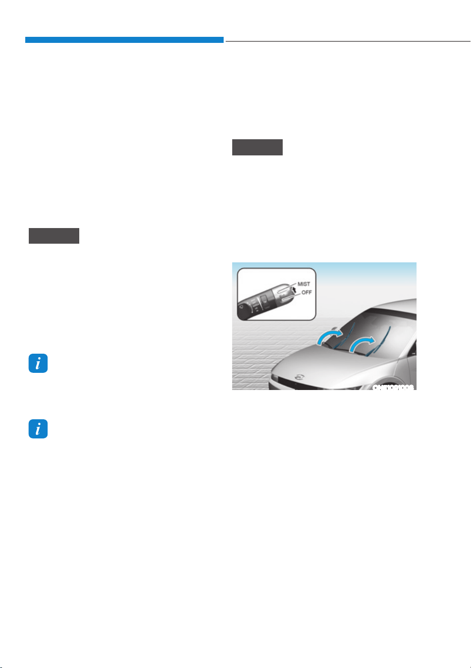
Maintenance
9-16
Blade Inspection
Contamination of either the windshield
or the wiper blades with foreign matter
can reduce the effectiveness of the
windshield wipers.
Common sources of contamination are
insects, tree sap, and hot wax treatments
used by some commercial car washes. If
the blades are not wiping properly, clean
both the window and the blades with a
good cleaner or mild detergent, and rinse
thoroughly with clean water.
NOTICE
To prevent damage to the wiper blades,
arms or other components, do not:
ś Use gasoline, kerosene, paint
thinner, or other solvents on or near
them.
ś Attempt to move the wipers
manually.
ś Use non-specified wiper blades.
Information
Commercial hot waxes applied by
automatic car washes have been known to
make the windshield difficult to clean.
Information
Wiper blades are consumable items.
Normal wear of the wipers may not be
covered by your vehicle warranty.
Blade Replacement
When the wipers no longer clean
adequately, the blades may be worn or
cracked, and require replacement.
NOTICE
ś In order to prevent damage to the
hood and the wiper arms, the wiper
arms should only be lifted when in
the top wiping position.
ś Always return the wiper arms to the
windshield before driving.
Front windshield wiper blade
replacement
ONE1091008
Within 20 seconds of turning off the
vehicle, lift up and hold the wiper lever
to the MIST position for about 2 seconds
until the wipers move to the top wipe
position.
At this time you can lift the wipers off the
windshield.
WIPER BLADES
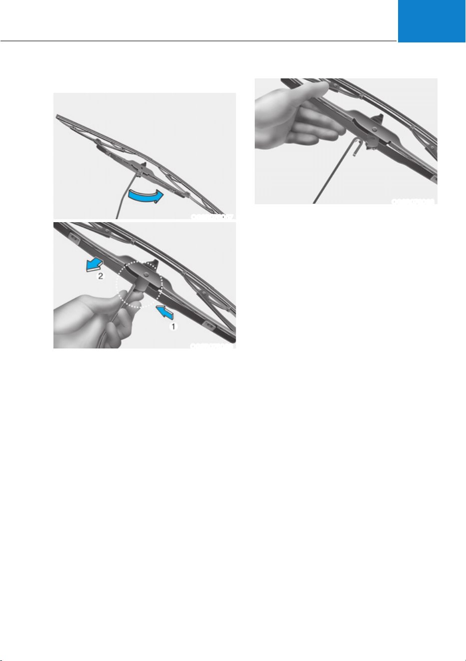
09
9-17
Type A
OGSR076067
OGSR076066
1. Lift up the wiper blade clip. Then lift
up the wiper blade.
2. While pushing the lock (1), pull down
the wiper blade (2).
OGSR076068
3. Remove the wiper blade from the
wiper arm.
4. Install a new wiper blade assembly in
the reverse order of removal.
5. Return the wiper arm on the
windshield.
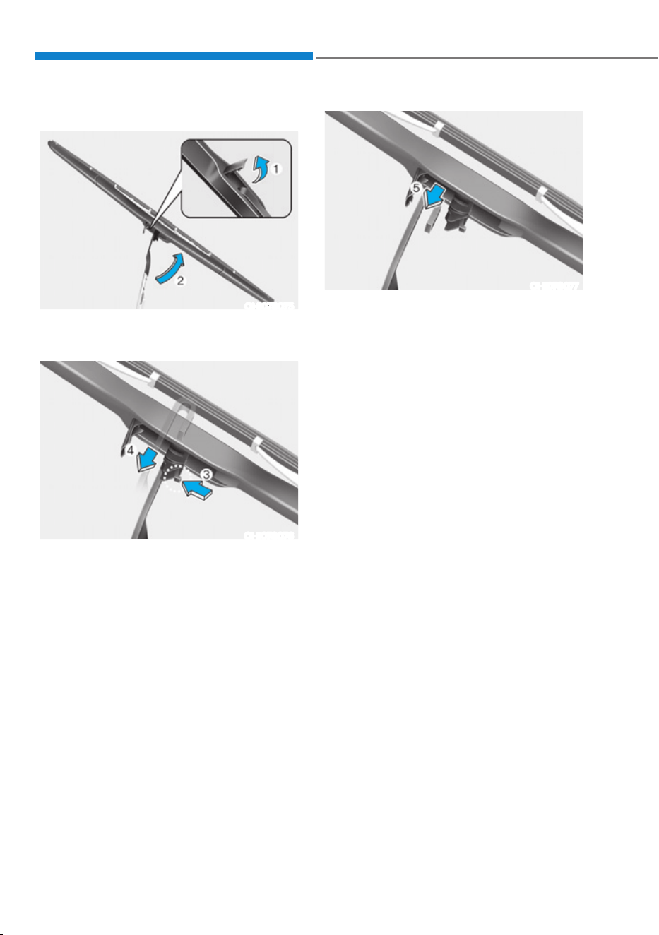
Maintenance
9-18
Type B
OHI078075
1. Lift up the wiper blade clip (1). Then
lift up the wiper blade.
OHI078076
2. Press the clip (3). Then push the blade
forward through the wiper arm to
disassemble it (4).
OHI078077
3. Remove the wiper blade from the
wiper arm (5).
4. Install the new blade assembly in the
reverse order of removal.
5. Return the wiper arm on the
windshield.
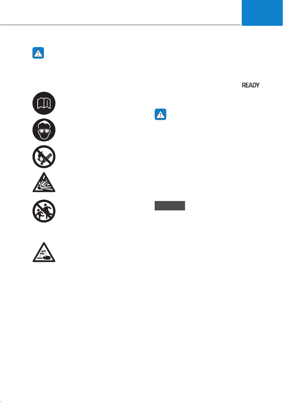
09
9-19
WARNING
To prevent SERIOUS INJURY or DEATH
to you or bystanders, always follow
these precautions when working near
or handling the battery:
Always read and follow
instructions carefully when
handling a battery.
Wear eye protection designed
to protect the eyes from acid
splashes.
Keep all flames, sparks, or
smoking materials away from
the battery.
Hydrogen is always present
in battery cells, is highly
combustible, and may explode
if ignited.
Keep batteries out of reach of
children.
Batteries contain sulfuric acid
which is highly corrosive. Do
not allow acid to contact your
eyes, skin or clothing.
If acid gets into your eyes,
flush your eyes with clean
water for at least 15 minutes
and get immediate medical
attention. If acid gets on
your skin, thoroughly wash
the area. If you feel pain or a
burning sensation, get medical
attention immediately.
ś When lifting a plastic-cased battery,
excessive pressure on the case may
cause battery acid to leak. Lift with a
battery carrier or with your hands on
opposite corners.
ś Do not attempt to jump start your
vehicle if your battery is frozen.
ś NEVER attempt to recharge the
battery when the vehicle’s battery
cables are connected to the battery.
ś The electrical ignition switch works
with high voltage. NEVER touch
these components with the “
”
indicator ON or when the START/
STOP button is in the ON position.
WARNING
CALIFORNIA PROPOSITION 65
WARNING
Battery posts, terminals, and related
accessories contain lead and lead
compounds, chemicals known to the
State of California to cause cancer,
birth defects and reproductive harm.
Batteries also contain other chemicals
known to the State of California
to cause cancer. Wash hands after
handling.
NOTICE
Always follow these instructions when
handling your vehicle’s battery to
prevent damage to your battery:
ś When you do not use the vehicle for a
long time in a low temperature area,
disconnect the battery and keep it
indoors.
ś Always charge the battery fully to
prevent battery case damage in low
temperature areas.
ś Prevent liquid from wetting the
battery terminals. The performance
of the battery may be degraded, and
may cause injury. Be cautious when
loading liquid in the trunk.
ś Do not tilt the battery.
ś If you connect unauthorized
electronic devices to the battery, the
battery may be discharged. Never
use unauthorized devices.
%$77(5<ǣ92/7Ǥ
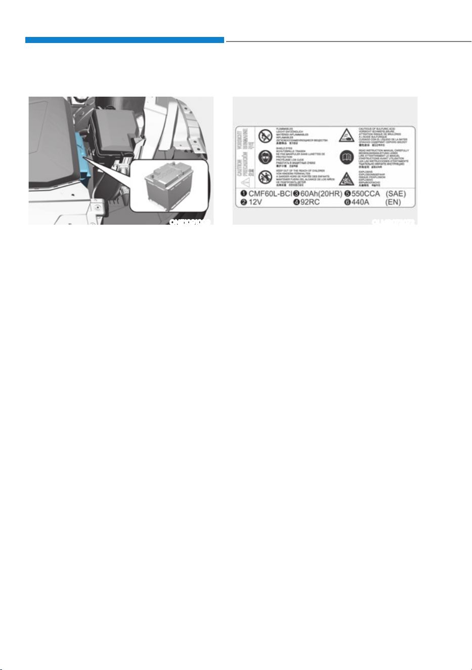
Maintenance
9-20
For best battery service
ONE1091009
ś Keep the battery securely mounted.
ś Keep the battery top clean and dry.
ś Keep the terminals and connections
clean, tight, and coated with
petroleum jelly or terminal grease.
ś Rinse any spilled electrolyte from the
battery immediately with a solution of
water and baking soda.
ś If the vehicle is not going to be used
for an extended time, disconnect the
battery cables.
Battery Capacity Label
OLMB073072
à The actual battery label in the vehicle
may differ from the illustration.
1. CMF60L-BCI : The HYUNDAI model
name of battery
2. 12V : The nominal voltage
3. 60Ah(20HR) : The nominal capacity
(in Ampere hours)
4. 92RC : The nominal reserve capacity
(in min.)
5. 550CCA : The cold-test current in
amperes by SAE
6. 440A : The cold-test current in
amperes by EN
Battery Recharging
By battery charger
Your vehicle has a maintenance-free,
calcium-based battery.
ś If the battery becomes discharged
over a short time (because, for
example, the headlamps or interior
lights were left on while the vehicle
was not in use), recharge it by slow
charging (trickle) for 10 hours.
ś If the battery gradually discharges
because of high electrical load while
the vehicle is being used, recharge it
at 20-30A for two hours.

09
9-21
WARNING
Always follow these instructions when
recharging your vehicle’s battery to
avoid the risk of SERIOUS INJURY or
DEATH from explosions or acid burns:
ś Before performing maintenance or
recharging the battery, turn off all
accessories and stop the vehicle.
ś Keep all flames, sparks, or smoking
materials away from the battery.
ś Always work outdoors or in an area
with plenty of ventilation.
ś Wear eye protection when checking
the battery during charging.
ś The battery must be removed from
the vehicle and placed in a well
ventilated area.
ś Watch the battery during charging,
and stop or reduce the charging
rate if the battery cells begin boiling
violently.
ś The negative battery cable must
be removed first and installed last
when the battery is disconnected.
Disconnect the battery charger in the
following order:
1. Turn off the battery charger main
switch.
2. Unhook the negative clamp from
the negative battery terminal.
3. Unhook the positive clamp from
the positive battery terminal.
ś Use batteries for replacement from
an authorized HYUNDAI dealer.
By jump starting
After a jump start from a good battery,
drive the vehicle for 20-30 minutes
before it is shutoff. The vehicle may
not restart if you shut it off before the
battery had a chance to adequately
recharge. See “Jump Starting” in chapter
8 for more information on jump starting
procedures.
Information
An inappropriately disposed
battery can be harmful to the
environment and human health.
Dispose of the battery according
to your local law(s) or regulation.
Reset Items
The following items may need to be reset
after the battery has been discharged or
the battery has been disconnected.
ś Driving info/After recharging/
Accumulated info (items in Utility
view) (see chapter 4)
ś Integrated memory system (see
chapter 5)
ś Power window (see chapter 5)
ś Vision roof (see chapter 5)
ś Power liftgate (see chapter 5)
ś Climate control system (see chapter 5)
ś Clock (see Infotainment system
manual)
ś Infotainment system (see
Infotainment system manual)
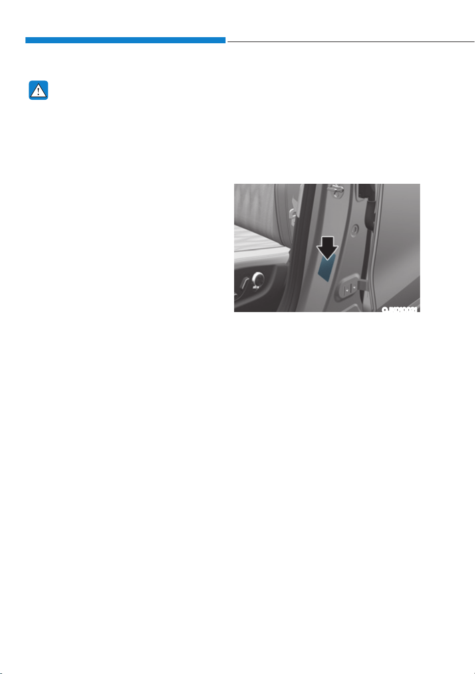
Maintenance
9-22
WARNING
Tire failure may cause loss of
vehicle control resulting in an
accident. To reduce risk of SERIOUS
INJURY or DEATH, take the
following precautions:
ś Inspect your tires monthly for
proper inflation as well as wear
and damage.
ś The recommended cold tire
pressure for your vehicle can be
found in this manual and on the
tire label located on the driver’s
side center pillar. Always use a
tire pressure gauge to measure
tire pressure. Tires with too
much or too little pressure wear
unevenly causing poor handling.
ś Check the pressure of the
spare every time you check the
pressure of the other tires on
your vehicle.
ś Replace tires that are worn, show
uneven wear, or are damaged.
Worn tires can cause loss of
braking effectiveness, steering
control, or traction.
ś ALWAYS replace tires with the
same size, type, construction and
tread pattern as each tire that
was originally supplied with this
vehicle. Using tires and wheels
other than the recommended
sizes could cause unusual
handling characteristics, poor
vehicle control, or negatively
affect your vehicle’s Anti-Lock
Brake System (ABS) resulting in a
serious accident.
Tire Care
For proper maintenance, safety,
and maximum electric energy
economy, you must always maintain
recommended tire inflation
pressures and stay within the load
limits and weight distribution
recommended for your vehicle.
OJK010021
All specifications (sizes and
pressures) can be found on a label
attached to the driver’s side center
pillar.
Recommended Cold Tire
Inflation Pressures
All tire pressures (including the
spare) should be checked when the
tires are cold. “Cold tires” means the
vehicle has not been driven for at
least three hours or driven less than
one mile (1.6 km).
Warm tires normally exceed
recommended cold tire pressures
by 4 to 6 psi (28 to 41 kPa). Do not
release air from warm tires to adjust
the pressure or the tires will be
under-inflated. For recommended
inflation pressure, refer to “Tire and
Wheels” section in chapter 2.
TIRES AND WHEELS

09
9-23
WARNING
Recommended pressures must be
maintained for the best ride, vehicle
handling, and minimum tire wear.
Over-inflation or under-inflation
can reduce tire life, adversely
affect vehicle handling, and lead to
sudden tire failure that could result
in loss of vehicle control resulting in
an accident.
Severe under-inflation can lead
to severe heat build-up, causing
blowouts, tread separation and
other tire failures that can result in
the loss of vehicle control resulting
in an accident. This risk is much
higher on hot days and when
driving for long periods at high
speeds.
CAUTION
ś Under-inflation results in
excessive wear, poor handling
and reduced electric energy
economy. Wheel deformation
is also possible. Keep your tire
pressures at the proper levels. If
a tire frequently needs refilling,
have it checked by an authorized
HYUNDAI dealer.
ś Over-inflation produces a harsh
ride, excessive wear at the center
of the tire tread, and a greater
possibility of damage from road
hazards.
Check Tire Inflation Pressure
Check your tires, including the spare
tire, once a month or more.
How to check
Use a good quality tire pressure
gauge to check tire pressure. You
can not tell if your tires are properly
inflated simply by looking at them.
Radial tires may look properly
inflated when they are under-
inflated.
Remove the valve cap from the tire
valve stem. Press the tire gauge
firmly onto the valve to get a
pressure measurement. If the cold
tire inflation pressure matches the
recommended pressure on the tire
and loading information label, no
further adjustment is necessary. If
the pressure is low, add air until you
reach the recommended pressure.
Make sure to put the valve caps
back on the valve stems. Without
the valve cap, dirt or moisture could
get into the valve core and cause
air leakage. If a valve cap is missing,
install a new one as soon as possible.
If you overfill the tire, release air by
pushing on the metal stem in the
center of the tire valve. Recheck the
tire pressure with the tire gauge. Be
sure to put the valve caps back on
the valve stems. Without the valve
cap, dirt or moisture could get into
the valve core and cause air leakage.
If a valve cap is missing, install a new
one as soon as possible.
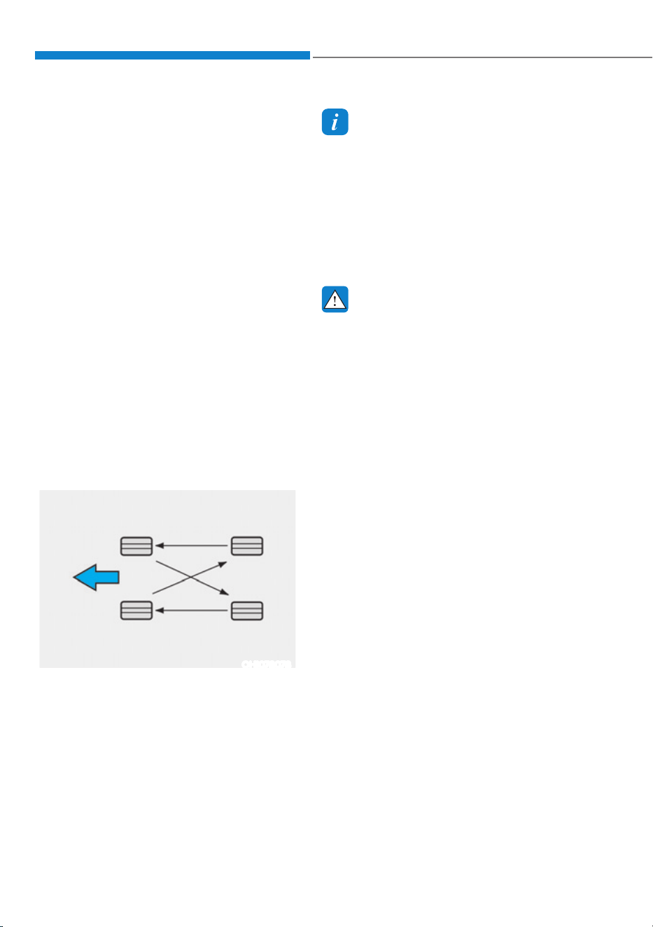
Maintenance
9-24
Tire Rotation
To equalize tread wear, HYUNDAI
recommends that the tires be
rotated every 5,000 miles (8,000 km)
or sooner if irregular wear develops.
During rotation, check the tires for
correct balance.
When rotating tires, check for
uneven wear and damage. Abnormal
wear is usually caused by incorrect
tire pressure, improper wheel
alignment, out-of-balance wheels,
severe braking or severe cornering.
Look for bumps or bulges in the
tread or side of the tire. Replace
the tire if you find any of these
conditions. Replace the tire if fabric
or cord is visible. After rotation, be
sure to bring the front and rear tire
pressures to specification and check
wheel lug nut tightness (proper
torque is 11~13kgf·m (79~94 lbf·ft).
OHI078078
Disc brake pads should be inspected
for wear whenever tires are rotated.
Information
The outside and inside of the
unsymmetrical tire is distinguishable.
When installing an unsymmetrical
tire, be sure to install the side marked
“outside” face the outside. If the side
marked “inside” is installed on the
outside, it will have a negative effect
on vehicle performance.
WARNING
ś Do not use the compact spare
tire for tire rotation.
ś Do not mix bias ply and radial ply
tires under any circumstances.
This may cause unusual handling
characteristics that may cause
loss of vehicle control resulting in
an accident.
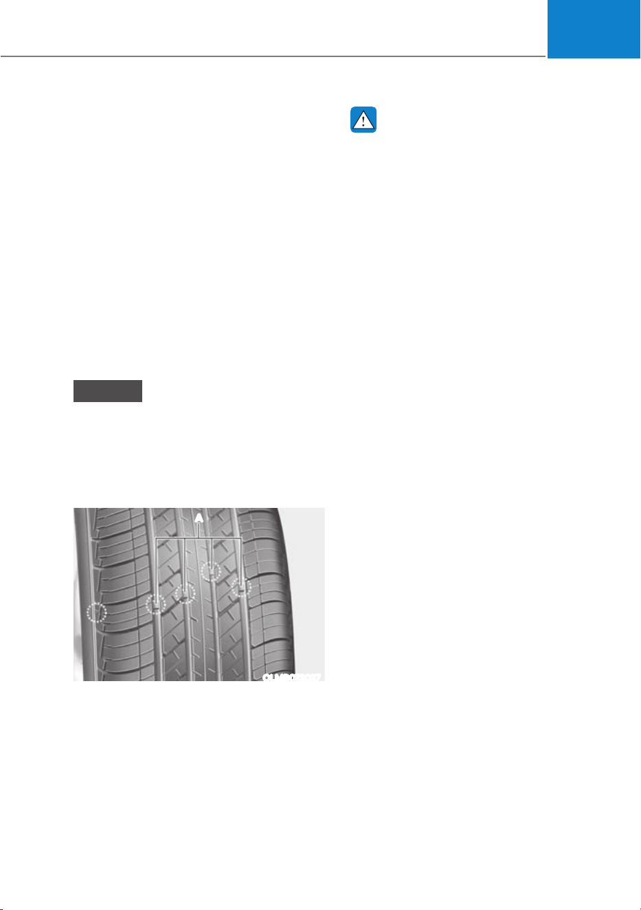
09
9-25
Wheel Alignment and Tire
Balance
The wheels on your vehicle were
aligned and balanced carefully at the
factory to give you the longest tire
life and best overall performance.
In most cases, you will not need to
have your wheels aligned again.
However, if you notice unusual tire
wear or your vehicle pulling one way
or the other, the alignment may need
to be reset.
If you notice your vehicle vibrating
when driving on a smooth road, your
wheels may need to be rebalanced.
NOTICE
Incorrect wheel weights can
damage your vehicle’s aluminum
wheels. Use only approved wheel
weights.
Tire Replacement
OLMB073027
A
[A] : Tread wear indicator
If the tire is worn evenly, a tread
wear indicator will appear as a solid
band across the tread. This shows
there is less than 1/16 in. (1.6 mm) of
tread left on the tire. Replace the tire
when this happens.
Do not wait for the band to appear
across the entire tread before
replacing the tire.
WARNING
To reduce the risk of DEATH or
SERIOUS INJURY:
ś Replace tires that are worn, show
uneven wear, or are damaged.
Worn tires can cause loss of
braking effectiveness, steering
control, and traction.
ś Always replace tires with the
same size as each tire that was
originally supplied with this
vehicle. Using tires and wheels
other than the recommended
sizes could cause unusual
handling characteristics, poor
vehicle control, or negatively
affect your vehicle’s Anti-Lock
Brake System (ABS) resulting in a
serious accident.
ś When replacing tires (or wheels),
it is recommended to replace
the two front or two rear tires (or
wheels) as a pair. Replacing just
one tire can seriously affect your
vehicle’s handling.
ś Tires degrade over time, even
when they are not being used.
Regardless of the remaining
tread, HYUNDAI recommends
that tires be replaced after six (6)
years of normal service.
ś Heat caused by hot climates or
frequent high loading conditions
can accelerate the aging process.
Failure to follow this warning
may cause sudden tire failure,
which could lead to a loss of
vehicle control resulting in an
accident.
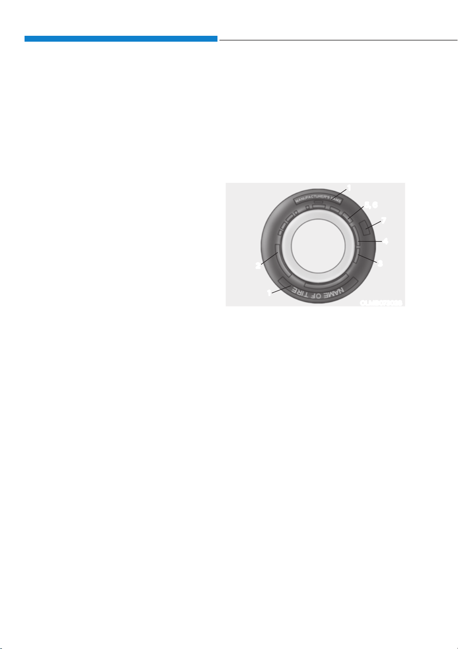
Maintenance
9-26
Wheel Replacement
When replacing the metal wheels
for any reason, make sure the new
wheels are equivalent to the original
factory units in diameter, rim width
and offset.
Tire Traction
Tire traction can be reduced if you
drive on worn tires, tires that are
improperly inflated or on slippery
road surfaces. Tires should be
replaced when tread wear indicators
appear. To reduce the possibility of
losing control, slow down whenever
there is rain, snow or ice on the road.
Tire Maintenance
In addition to proper inflation,
correct wheel alignment helps to
decrease tire wear. If you find a tire
is worn unevenly, have your dealer
check the wheel alignment.
When you have new tires installed,
make sure they are balanced. This
will increase vehicle ride comfort
and tire life. Additionally, a tire
should always be rebalanced if it is
removed from the wheel.
Tire Sidewall Labeling
This information identifies and
describes the fundamental
characteristics of the tire and also
provides the Tire Identification
Number (TIN) for safety standard
certification. The TIN can be used to
identify the tire in case of a recall.
OLMB073028
3
5, 6
1
7
1
2
4
1. Manufacturer or brand name
Manufacturer or brand name is
shown.
2. Tire size designation
A tire’s sidewall is marked with a
tire size designation. You will need
this information when selecting
replacement tires for your car.
The following explains what the
letters and numbers in the tire size
designation mean.

09
9-27
Example tire size designation:
(These numbers are provided as
an example only; your tire size
designator could vary depending on
your vehicle.)
235/55R19 105W
235 - Tire width in millimeters.
55 - Aspect ratio. The tire’s section
height as a percentage of its
width.
R - Tire construction code (Radial).
19 - Rim diameter in inches.
105 - Load Index, a numerical code
associated with the maximum
load the tire can carry.
W - Speed Rating Symbol. See
the speed rating chart in
this section for additional
information.
Wheel size designation
Wheels are also marked with
important information that you need
if you ever have to replace one. The
following explains what the letters
and numbers in the wheel size
designation mean.
Example wheel size designation:
7.5J X 19
7.5 - Rim width in inches.
J - Rim contour designation.
19 - Rim diameter in inches.
Tire speed ratings
The chart below lists many of the
different speed ratings currently
being used for passenger vehicle
tires. The speed rating is part of the
tire size designation on the sidewall
of the tire. This symbol corresponds
to that tire’s designed maximum safe
operating speed.
Speed Rating
Symbol
Maximum Speed
S 112 mph (180 km/h)
T 118 mph (190 km/h)
H 130 mph (210 km/h)
V 149 mph (240 km/h)
W 168 mph (270 km/h)
Y 186 mph (300 km/h)
3. Checking tire life (TIN : Tire
Identification Number)
Any tires that are over six years old,
based on the manufacturing date,
(including the spare tire) should be
replaced by new ones. You can find
the manufacturing date on the tire
sidewall (possibly on the inside of
the wheel), displaying the DOT Code.
The DOT Code is a series of numbers
on a tire consisting of numbers and
English letters. The manufacturing
date is designated by the last four
digits (characters) of the DOT code.
DOT : XXXX XXXX OOOO
The front part of the DOT shows a
plant code number, tire size and
tread pattern and the last four
numbers indicate week and year
manufactured.
For example:
DOT XXXX XXXX 1522 represents that
the tire was produced in the 15th
week of 2022.

Maintenance
9-28
4. Tire ply composition and material
The number of layers or plies of
rubber-coated fabric in the tire. Tire
manufacturers also must indicate the
materials in the tire, which include
steel, nylon, polyester, and others.
The letter “R” means radial ply
construction; the letter “D“ means
diagonal or bias ply construction;
and the letter “B” means belted-bias
ply construction.
5. Maximum permissible inflation
pressure
This number is the greatest amount
of air pressure that should be put in
the tire. Do not exceed the maximum
permissible inflation pressure. Refer
to the Tire and Loading Information
label for recommended inflation
pressure.
6. Maximum load rating
This number indicates the maximum
load in kilograms and pounds that
can be carried by the tire. When
replacing the tires on the vehicle,
always use a tire that has the same
load rating as the factory installed
tire.
7. Uniform tire quality grading
Quality grades can be found where
applicable on the tire sidewall
between tread shoulder and
maximum section width.
For example:
TREADWEAR 200
TRACTION AA
TEMPERATURE A
Tread wear
The tread wear grade is a
comparative rating based on the
wear rate of the tire when tested
under controlled conditions on a
specified government test course.
For example, a tire graded 150 would
wear one-and-a-half times (1½) as
well on the government course as a
tire graded 100.
The relative performance of tires
depends upon the actual conditions
of their use, however, and may
depart significantly from the norm
due to variations in driving habits,
service practices and differences in
road characteristics and climate.
These grades are molded on the
sidewalls of passenger vehicle tires.
The tires available as standard or
optional equipment on your vehicle
may vary with respect to grade.
Traction - AA, A, B & C
The traction grades, from highest
to lowest, are AA, A, B and C. Those
grades represent the tire’s ability to
stop on wet pavement as measured
under controlled conditions on
specified government test surfaces
of asphalt and concrete. A tire
marked C may have poor traction
performance.
WARNING
The traction grade assigned to
this tire is based on straight ahead
braking traction tests, and does not
include acceleration, cornering,
hydroplaning, or peak traction
characteristics.

09
9-29
Temperature - A, B & C
The temperature grades are A (the
highest), B and C representing the
tire’s resistance to the generation
of heat and its ability to dissipate
heat when tested under controlled
conditions on a specified indoor
laboratory test wheel.
Sustained high temperature can
cause the material of the tire to
degenerate and reduce tire life,
and excessive temperature can
lead to sudden tire failure. Grades
B and A represent higher levels of
performance on the laboratory test
wheel than the minimum required
by law.
WARNING
The temperature grade for this
tire is established for a tire that
is properly inflated and not
overloaded. Excessive speed,
under-inflation, over-inflation, or
excessive loading, either separately
or in combination, can cause heat
build-up and possible sudden
tire failure. This may cause loss
of vehicle control resulting in an
accident.
Tire Terminology and Definitions
Air pressure
The amount of air inside the tire
pressing outward on the tire. Air
pressure is expressed in pounds per
square inch (psi) or kilopascal (kPa).
Accessory weight
This means the combined weight
of optional accessories. Some
examples of optional accessories
are automatic transmission, power
seats, and air conditioning.
Aspect ratio
The relationship of a tire’s height to
its width.
Belt
A rubber coated layer of cords that
is located between the plies and the
tread. Cords may be made from steel
or other reinforcing materials.
Bead
The tire bead contains steel wires
wrapped by steel cords that hold the
tire onto the rim.

Maintenance
9-30
Bias ply tire
A pneumatic tire in which the plies
are laid at alternate angles less than
90 degrees to the centerline of the
tread.
Cold tire pressure
The amount of air pressure in a tire,
measured in pounds per square inch
(psi) or kilopascals (kPa) before a tire
has built up heat from driving.
Curb weight
This means the weight of a motor
vehicle with standard and optional
equipment including the maximum
capacity of fuel, oil and coolant, but
without passengers and cargo.
DOT markings
A code molded into the sidewall
of a tire signifying that the tire
is in compliance with the U.S.
Department of Transportation motor
vehicle safety standards. The DOT
code includes the Tire Identification
Number (TIN), an alphanumeric
designator which can also identify
the tire manufacturer, production
plant, brand and date of production.
GVWR
Gross Vehicle Weight Rating
GAWR FRT
Gross Axle Weight Rating for the
Front Axle.
GAWR RR
Gross Axle Weight Rating for the
Rear axle.
Intended outboard sidewall
The side of an asymmetrical tire,
that must always face outward when
mounted on a vehicle.
Kilopascal (kPa)
The metric unit for air pressure.
Light Truck (LT) tire
A tire designated by its manufacturer
as primarily intended for use on
lightweight trucks or multipurpose
passenger vehicles.
Load ratings
The maximum load that a tire is rated
to carry for a given inflation pressure.
Load index
An assigned number ranging from 1
to 279 that corresponds to the load
carrying capacity of a tire.
Maximum inflation pressure
The maximum air pressure to which
a cold tire may be inflated. The
maximum air pressure is molded
onto the sidewall.
Maximum load rating
The load rating for a tire at the
maximum permissible inflation
pressure for that tire.

09
9-31
Maximum loaded vehicle weight
The sum of curb weight; accessory
weight; vehicle capacity weight; and
production options weight.
Normal occupant weight
The number of occupants a vehicle
is designed to seat multiplied by 150
pounds (68 kg).
Occupant distribution
Designated seating positions.
Outward facing sidewall
An asymmetrical tire has a particular
side that faces outward when
mounted on a vehicle. The outward
facing sidewall bears white lettering
or bears manufacturer, brand, and/or
model name molding that is higher
or deeper than the same moldings
on the inner facing sidewall.
Passenger (P-Metric) tire
A tire used on passenger cars
and some light duty trucks and
multipurpose vehicles.
Ply
A layer of rubber-coated parallel
cords.
Pneumatic tire
A mechanical device made of rubber,
chemicals, fabric and steel or other
materials, that, when mounted on
an automotive wheel provides the
traction and contains the gas or fluid
that sustains the load.
Pneumatic options weight
The combined weight of installed
regular production options weighing
over 5 lb. (2.3 kg) in excess of the
standard items which they replace,
not previously considered in
curb weight or accessory weight,
including heavy duty breaks, ride
levelers, roof rack, heavy duty
battery, and special trim.
Recommended inflation pressure
Vehicle manufacturer’s
recommended tire inflation pressure
as shown on the tire placard.
Radial ply tire
A pneumatic tire in which the ply
cords that extend to the beads are
laid at 90 degrees to the centerline
of the tread.
Rim
A metal support for a tire and upon
which the tire beads are seated.
Sidewall
The portion of a tire between the
tread and the bead.
Speed rating
An alphanumeric code assigned to a
tire indicating the maximum speed
at which a tire can operate.

Maintenance
9-32
Traction
The friction between the tire and
the road surface. The amount of grip
provided.
Tread
The portion of a tire that comes into
contact with the road.
Treadwear indicators
Narrow bands, sometimes called
“wear bars”, that show across the
tread of a tire when only 1/16 inch of
tread remains.
UTQGS
Uniform Tire Quality Grading
Standards is a tire information
system that provides consumers
with ratings for a tire’s traction,
temperature and treadwear.
Ratings are determined by tire
manufacturers using government
testing procedures. The ratings are
molded into the sidewall of the tire.
Vehicle capacity weight
The number of designated seating
positions multiplied by 150 lbs. (68
kg) plus the rated cargo and luggage
load.
Vehicle maximum load on the tire
Load on an individual tire due to curb
and accessory weight plus maximum
occupant and cargo weight.
Vehicle normal load on the tire
Load on an individual tire that is
determined by distributing to each
axle its share of the curb weight,
accessory weight, and normal
occupant weight and dividing by 2.
Vehicle placard
A label permanently attached
to a vehicle showing the
original equipment tire size and
recommended inflation pressure.

09
9-33
All Season Tires
HYUNDAI specifies all season
tires on some models to provide
good performance for use all year
round, including snowy and icy
road conditions. All season tires
are identified by ALL SEASON and/
or M+S (Mud and Snow) on the tire
sidewall. Snow tires have better
snow traction than all season tires
and may be more appropriate in
some areas.
Summer Tires
HYUNDAI specifies summer tires on
some models to provide superior
performance on dry roads. Summer
tire performance is substantially
reduced in snow and ice. Summer
tires do not have the tire traction
rating M+S (Mud and Snow) on
the tire side wall. If you plan to
operate your vehicle in snowy or icy
conditions, Genesis Branded Vehicle
recommends the use of snow tires or
all season tires on all four wheels.
Snow Tires
If you equip your car with snow
tires, they should be the same size
and have the same load capacity as
the original tires. Snow tires should
be installed on all four wheels;
otherwise, poor handling may result.
Snow tires should carry 4 psi (28 kPa)
more air pressure than the pressure
recommended for the standard
tires on the tire label on the driver’s
side of the center pillar, or up to the
maximum pressure shown on the tire
sidewall, whichever is less. Do not
drive faster than 75 mph (120 km/h)
when your vehicle is equipped with
snow tires.
Radial-Ply Tires
Radial-ply tires provide improved
tread life, road hazard resistance
and smoother high speed ride. The
radial-ply tires used on this vehicle
are of belted construction, and are
selected to complement the ride
and handling characteristics of
your vehicle. Radial-ply tires have
the same load carrying capacity,
as bias-ply or bias belted tires of
the same size, and use the same
recommended inflation pressure.
Mixing of radial-ply tires with
bias-ply or bias belted tires is not
recommended. Any combinations of
radial-ply and bias-ply or bias belted
tires when used on the same vehicle
will seriously deteriorate vehicle
handling. The best rule to follow
is: Identical pairs of radial-ply tires
should always be used as a set for
the front tires and a set for the rear
tires.
Longer wearing tires can be more
susceptible to irregular tread wear.
It is very important to follow the tire
rotation interval in this chapter to
achieve the tread life potential of
these tires. Cuts and punctures in
radial-ply tires are repairable only in
the tread area, because of sidewall
flexing. Consult your tire dealer for
radial-ply tire repairs.
WARNING
Do not mix bias ply and radial ply
tires under any circumstances.
This may cause unusual handling
characteristics that may cause loss
of vehicle control resulting in an
accident.

Maintenance
9-34
Low Aspect Ratio Tires
The aspect ratio is lower than 50 on
low aspect ratio tires.
Because low aspect ratio tires are
optimized for handling and braking,
their sidewall is a little stiffer than a
standard tire. Also, low aspect ratio
tires tend to be wider so that they
consequently have a greater contact
patch with the road surface. In some
instances, they may generate more
road noise compared with standard
tires.
CAUTION
The side wall of a low aspect ratio
tire is shorter than the normal one.
Thus, the low-aspect wheel and
tire are easily damaged. Follow the
below instructions.
ś When driving on a rough road or
driving off a road, be careful not
to damage the tires and wheels.
After driving, inspect the tires
and wheels.
ś When passing over a pothole,
speed bump, manhole, or curb
stone, drive the vehicle slowly so
as not to damage the tires and
wheels.
ś When there is an impact on a tire,
inspect the tire condition. Or,
contact an authorized retailer of
Genesis Branded products.
ś Inspect the tire condition and
pressure every 1,800 miles (3,000
km) to prevent tire damage.
ś It is difficult to recognize a tire
damage only with your eyes.
When there is a slight hint of a
tire damage, check and replace
the tire to prevent the damage
caused by air leakage.
ś When a tire is damaged while
driving on a rough road, off a
road, or over obstacles, such as a
pothole, manhole, or curb stone,
your warranty does not cover the
damage.
ś The tire information is specified
on the tire side wall.
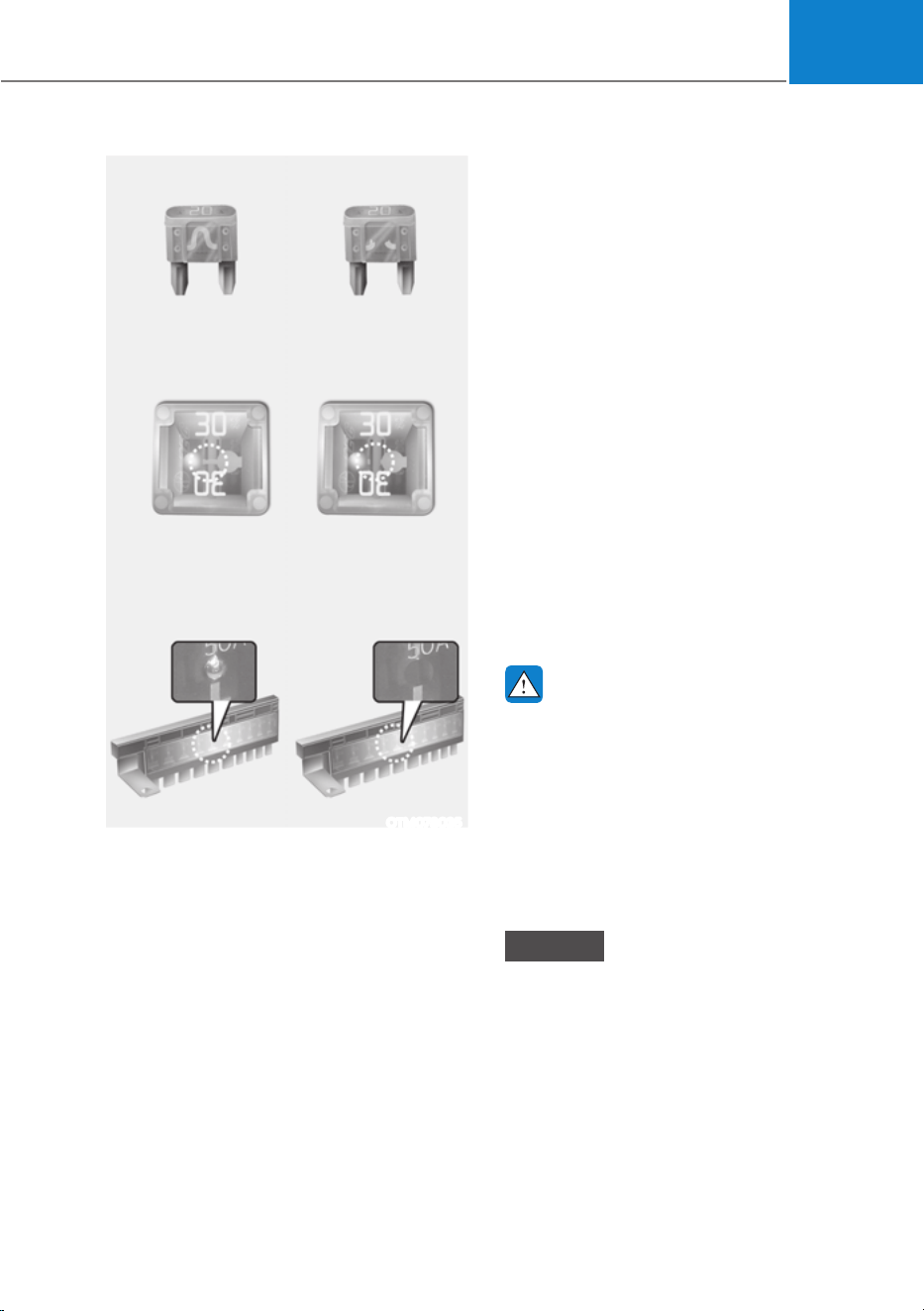
09
9-35
Ŷ
Blade type
Ŷ
Cartridge type
Ŷ
Multi type
Normal Blown
Normal Blown
Normal Blown
OTM078035
A vehicle’s electrical system is protected
from electrical overload damage by
fuses.
This vehicle has 5 fuse panels, one
located in the driver’s side panel bolster,
the other in the vehicle compartment.
If any of your vehicle’s lights,
accessories, or controls do not work,
check the appropriate circuit fuse. If a
fuse has blown, the element inside the
fuse will be melted or broken.
If the electrical system does not work,
first check the driver’s side fuse panel.
Before replacing a blown fuse, turn the
vehicle and all switches off, and then
disconnect the negative battery cable.
Always replace a blown fuse with one of
the same rating.
If the replacement fuse blows, this
indicates an electrical problem. Avoid
using the system involved. Consult an
authorized HYUNDAI dealer.
WARNING
NEVER replace a fuse with anything but
another fuse of the same rating.
ś A higher capacity fuse could cause
damage and possibly cause a fire.
ś Do not install a wire or aluminum
foil instead of the proper fuse -
even as a temporary repair. It may
cause extensive wiring damage and
possibly a fire.
NOTICE
Do not use a screwdriver or any other
metal object to remove fuses because
it may cause a short circuit and damage
the system.
FUSES
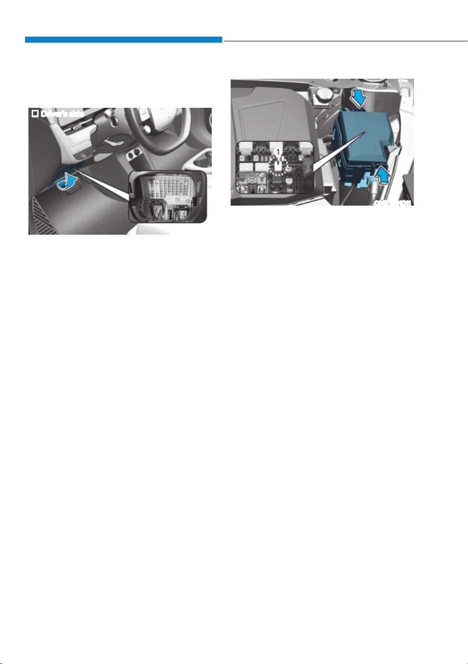
Maintenance
9-36
Instrument Panel Fuse
Replacement
Driver’s side
ONE1091010
1. Turn the vehicle off.
2. Turn all other switches off.
3. Open the fuse panel cover.
4. Refer to the label on the inside of
the fuse panel cover to locate the
suspected fuse location.
ONE1091011
5. Pull the suspected fuse straight out.
Use the removal tool (1) provided in
the motor compartment fuses panel
cover.
6. Check the removed fuse; replace it if
it is blown. Spare fuses are provided in
the instrument panel fuse panels (or in
the motor compartment fuse panel).
7. Push in a new fuse of the same
rating, and make sure it fits tightly in
the clips. If it fits loosely, consult an
authorized HYUNDAI dealer.
In an emergency, if you do not have
a spare fuse, use a fuse of the same
rating from a circuit you may not need
for operating the vehicle, such as the
cigarette lighter fuse.
If the headlamps or other electrical
components do not work and the fuses
are undamaged, check the fuse panel
in the motor compartment. If a fuse is
blown, it must be replaced with the same
rating.
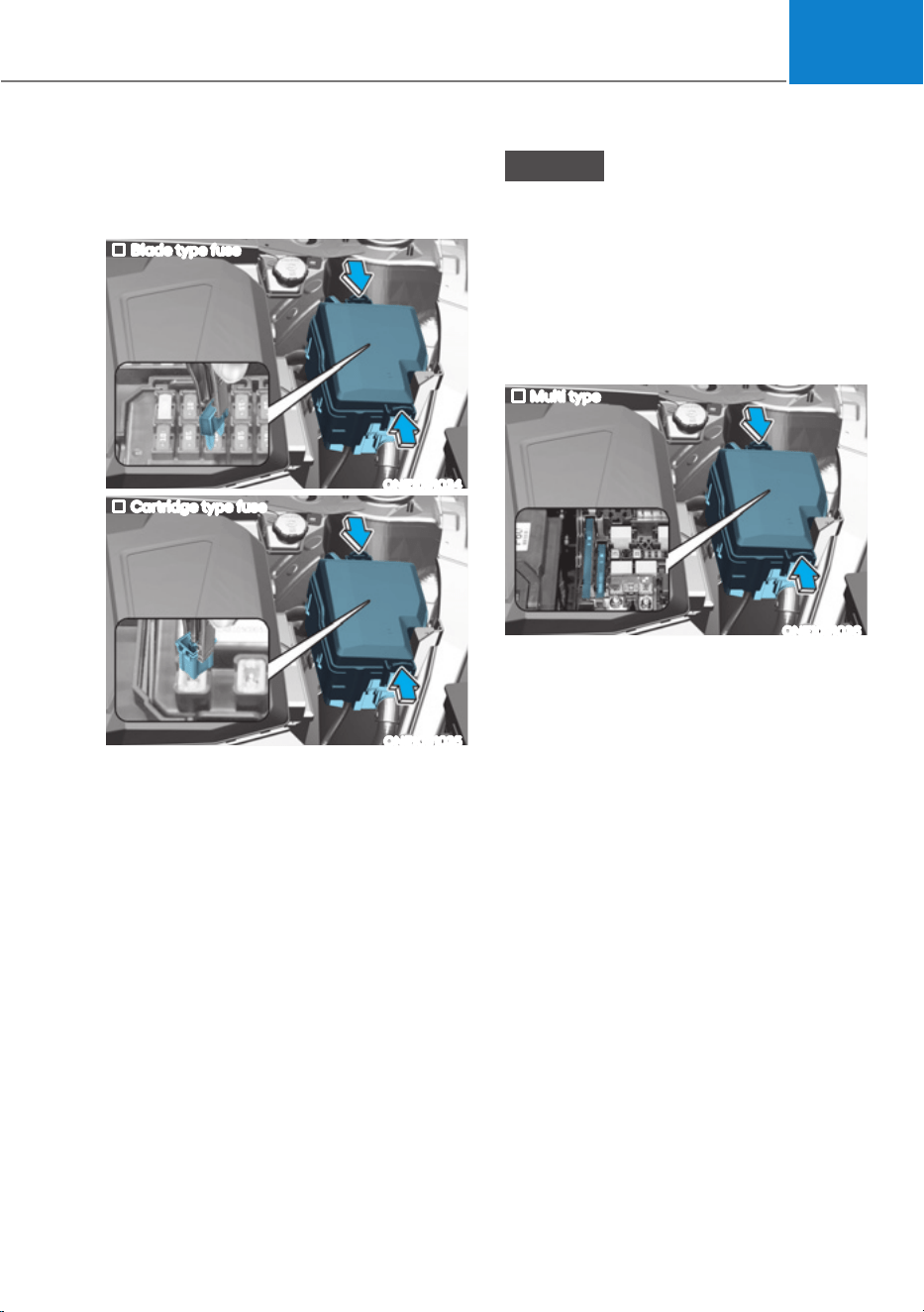
09
9-37
Motor Compartment Panel Fuse
Replacement
Blade fuse / Cartridge fuse
Blade type fuse
ONE1091034
Cartridge type fuse
ONE1091035
1. Turn the vehicle off.
2. Turn all other switches off.
3. Remove the fuse panel cover by
pressing the tap and pulling up.
4. Check the removed fuse; replace it
if it is blown. To remove or insert the
fuse, use the fuse puller in the motor
compartment fuse panel.
5. Push in a new fuse of the same
rating, and make sure it fits tightly in
the clips. If it fits loosely, consult an
authorized HYUNDAI dealer.
NOTICE
After checking the fuse panel in the
motor compartment, securely install
the fuse panel cover. You may hear a
clicking sound if the cover is securely
latched. If it is not securely latched,
electrical failure may occur from water
contact.
Multi fuse
Multi type
ONE1091036
If the multi fuse is blown, consult an
authorized HYUNDAI dealer.
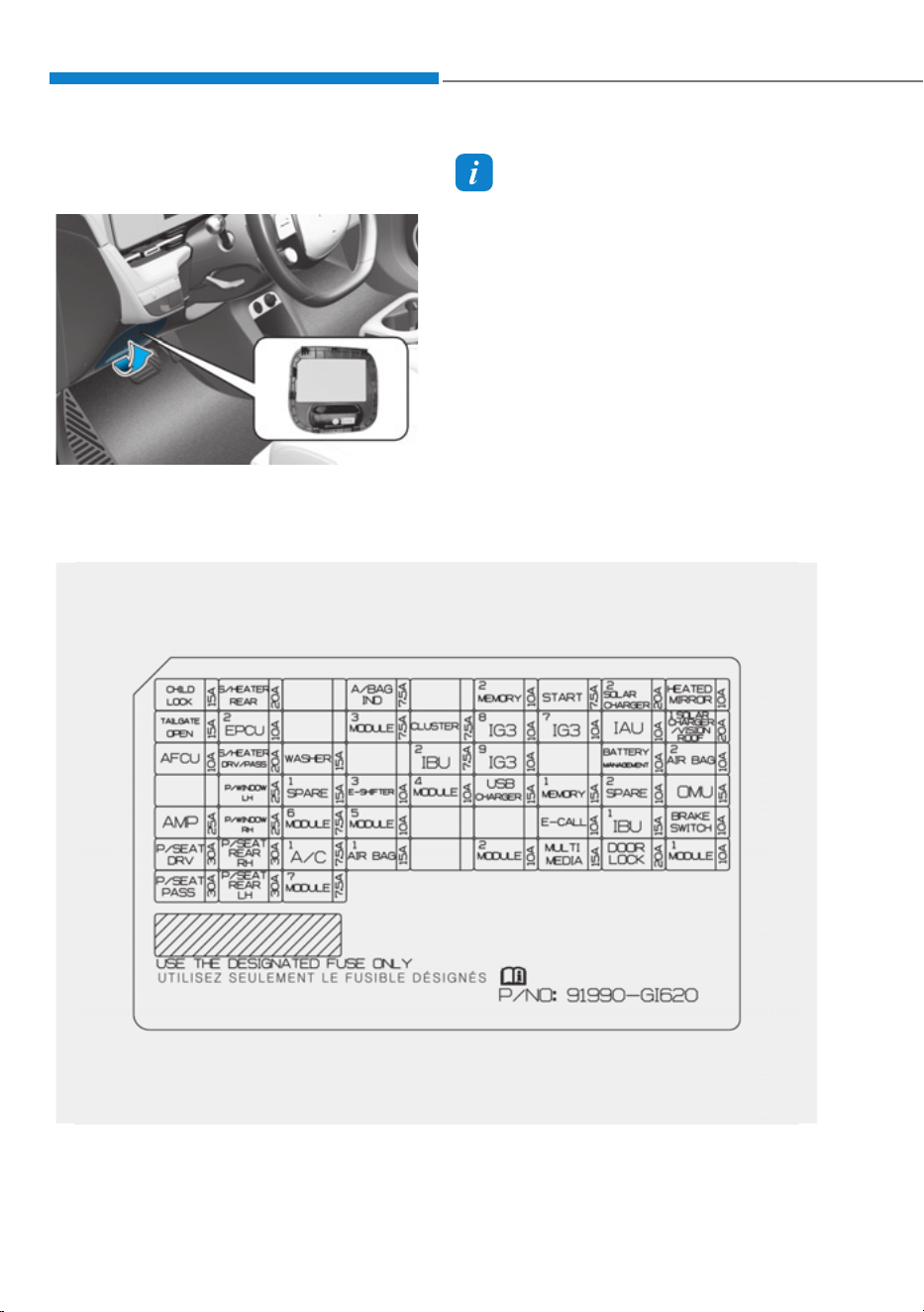
Maintenance
9-38
Fuse/Relay Panel Description
Instrument panel fuse panel
ONE1091012
Inside the fuse/relay box cover, you can
find the fuse/relay label describing fuse/
relay names and ratings.
Information
Not all fuse panel descriptions in this
manual may be applicable to your vehicle;
the information is accurate at the time of
printing. When you inspect the fuse box on
your vehicle, refer to the fuse box label.
ONE1091046N

09
9-39
Instrument panel fuse panel
Fuse Name
Fuse Rating Circuit Protected
Child Lock
15A Child Lock Relay, Child Unlock Relay
A/BAG IND
7.5A Overhead Console
MEMORY2
10A Head-Up Display
START
7.5A VCU, IBU
S/CHARGE2
20A SDC
MIRR HTR
10A
Driver Outside Mirror Unit, Passenger Outside Mirror
Unit
T/GATE
15A Liftgate Release Relay
EPCU2
10A Rear Inverter
MODULE3
7.5A
Multifunction Switch, IBU, Stop Lamp Switch, Driver
Door Module
CLUSTER
7.5A Head-Up Display, Instrument Cluster
IG3 8
10A
V2L Unit, ICCU, VCMS, Rear Electronic Oil Pump,
CDM
IG3 7
10A
Incar Temperature Sensor, A/V & Navigation
Head Unit, A/C PTC Heater, A/C Control Module,
Instrument Cluster, High-Voltage Charging Lamp
IAU
10A IAU, BLE UNIT
S/CHARGER/VISION
ROOF
20A SDC, Vison Roof
AFCU
10A AFCU, Driver/Passenger Door Outside Handle

Maintenance
9-40
Instrument panel fuse panel
Fuse Name
Fuse Rating Circuit Protected
FRT SEAT HEATER
20A
Front Air Ventilation Seat Control Module, Front Seat
Warmer Control Module
WASHER
15A Multifunction Switch
IBU2
7.5A IBU
IG3 9
10A SCU, Rear Inverter, BMU
BMS
10A BMU
A/BAG2
10A SRS Control Module
WIN LH
25A
Driver Safety Power Window Module, Passenger
Safety Power, Rear Power Window Switch LH
SPARE1
15A Not Used
E-SHIFTER3
10A Electronic ATM Shift Lever
MODULE4
10A
Front/Rear Corner Radar LH/RH, Front/Rear Inverter,
Crash Pad Switch, ADAS Driving ECU, VESS Unit,
Front Radar, Front View Camera, ADAS Parking ECU
USB CHARGER
15A Front USB Charger #1, Front USB Charger #2

09
9-41
Instrument panel fuse panel
Fuse Name
Fuse Rating Circuit Protected
MEMORY1
15A
ICU Junction Block (Fuse F6), Instrument Cluster,
A/C Control Module, Mood Lamp Unit
SPARE2
10A Not Used
OMU
15A
Driver/Passenger Outside Mirror Unit, Driver Door
Module
AMP
25A AMP
WIN RH
25A
Passenger Safety Power Window Module, Driver
Safety Power, Rear Power Window Switch RH
MODULE6
7.5A IBU, IAU
MODULE5
10A
Data Link Connector, Electro Chromic Mirror, E-CALL
Unit, A/V & Navigation Head Unit, Crash Pad Switch,
Head Lamp LH/RH, SDC, AMP, Smart Phone Wireless
Charger, Driver/Passenger Power Seat Module,
Front Air Ventilation Seat Control Module, Front Seat
Warmer Control, Module, Rear Power Seat LH/RH
Module
E-CALL
10A Not Used
IBU1
15A IBU
BRAKE SWITCH
10A Stop Lamp Switch, IBU
P/SEAT DRV
30A
Driver Power Seat Switch, Driver Power Seat Module
(With IMS)

Maintenance
9-42
Instrument panel fuse panel
Fuse Name
Fuse Rating Circuit Protected
P/SEAT RR RH
30A Rear Power Seat RH Module
A/C1
7.5A A/C Control Module
A/BAG1
15A SRS Control Module
MODULE2
10A
AMP, P/E Junction Block (Power Outlet Relay
(RLY.11)), IBU, ADAS Unit (Parking), A/V & Navigation
Keyboard, A/V & Navigation Head Unit
MULTIMEDIA
15A A/V & Navigation Head Unit
DR LOCK
20A Door Lock Relay, Door Unlock Relay
MODULE1
10A
Hazard Lamp Switch, Multifunction Switch, Data
Link Connector, Rain
Sensor, P/R Junction Block (Blower Relay (RLY.9)),
Driver/Passenger Door Speaker Mood Lamp, Driver/
Passenger Door Arm Rest Mood Lamp, Rear
Door Mood Lamp LH/RH, PTG Unit, Rear Power
Seat LH/RH Module, Driver/Passenger Power Seat
Module
P/SEAT PASS
30A
Passenger Power Seat Switch, Passenger Power Seat
Module
P/SEAT RR LH
30A Rear Power Seat LH Module
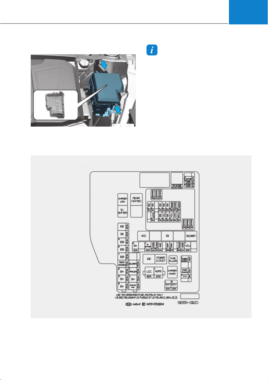
09
9-43
Motor compartment fuse panel
ONE1091013
Inside the fuse/relay box cover, you can
find the fuse/relay label describing fuse/
relay names and ratings.
Information
Not all fuse panel descriptions in this
manual may be applicable to your vehicle;
the information is accurate at the time of
printing. When you inspect the fuse panel
in your vehicle, refer to the fuse panel
label.
ONE1091047N

Maintenance
9-44
Motor compartment fuse panel
Type Fuse Name
Fuse Rating Circuit Protected
MULTI
FUSE-1
LDC
180A P/R Junction Block (Fuse : F15, F17, F20, F21)
MDPS1
100A MDPS Unit
MULTI
FUSE-2
B+5
60A
PCB Block (IG3 Main Relay, Fuse : F1, F2, F3,
F4, F6)
B+3
60A
ICU Junction Block (Fuse : F1, F2, F10, F11,
F19, F20,F29, F37, F38, F46, F47, F55, F56)
B+2
60A
ICU Junction Block (IPS1, IPS4, IPS6, IPS8,
IPS9, IPS10)
RR HTD
50A P/R Junction Block (RLY.3)
IEB1
60A IEB Unit
IEB2
60A IEB Unit
IEB4
40A Multipurpose Check Connector
IG1
40A P/R Junction Block (RLY.5, RLY.7)
IG2
40A P/R Junction Block (RLY.10)
MULTI
FUSE-3
C/FAN
80A Cooling Fan Motor
B+1
50A ICU Junction Block (IPS2, IPS3, IPS4, IPS5)
TRAILER1
50A Trailer Connector Unit
BLOWER
50A P/R Junction Block (RLY.9)

09
9-45
Type Fuse Name
Fuse Rating Circuit Protected
FUSE
B+4
40A
ICU Junction Block (Long Term Load Latch
Relay,
Fuse : F8, F17, F18, F26, F27, F35, F36, F45,
F44, F53, F54)
E-SHIFTER1
40A P/R Junction Block (RLY.2, Fuse : F22)
CHARGER1
10A
P/R Junction Block (RLY.1, RLY.12), ICCU,
VCMS
CHARGER2
10A CDM
AMS
10A 12V Battery Sensor
EWP1
20A Electronic Water Pump #1
EWP2
20A Electronic Water Pump #2
TRAILER2
20A Trailer Connector Unit
VESS
10A VESS Unit
VCU1
40A VCU

Maintenance
9-46
Type Fuse Name
Fuse Rating Circuit Protected
FUSE
P/OUTLET1
40A P/R Junction Block (RLY.11)
T/GATE
30A PTG Unit
A/C2
15A A/C Control Module
EOP1
40A Rear Electronic Oil Pump
EOP2
40A Front Electronic Oil Pump (AWD)
E-SHIFTER2
10A
P/R Junction Block (RLY.2), SCU, Electronic
ATM Shift Lever
P/OUTLET3
20A Rear Power Outlet
P/OUTLET2
20A Front Power Outlet

09
9-47
Fuse Name
Fuse Rating Circuit Protected
WIPER1
25A PCB Block (Wiper Main Relay)
EPCU1
15A Front Inverter (AWD)
HORN
15A
PCB Block (Horn Relay), PCB Block (Burglar Alarm
Horn Relay)
WIPER2
7.5A IBU
VCU2
15A VCU
IG3 1
20A ICU Junction Block (Fuse : F14, F16, F24)
IG3 3
15A Electronic Water Pump
IG3 5
10A BMS Coolant 3Way Valve
VCU3
10A VCU
IG3 4
10A
A/C Coolant Valve, Electronic Water Pump #1, #2,
Electronic A/C Compressor
IEB3
10A Multipurpose Check Connector, IEB Unit
IG3 6
10A Cooling Fan Motor, Front Electronic Oil Pump (AWD)
MDPS2 *
1
10A MDPS Unit
IG3 2
15A Front Inverter (AWD), VCU
*1 :
MDPS (Motor Driven Power Steering) is the same as EPS (Electric Power Steering)

Maintenance
9-48
Consult an authorized HYUNDAI dealer
to replace most vehicle light bulbs. It is
difficult to replace vehicle light bulbs
because other parts of the vehicle must
be removed before you can get to the
bulb. This is especially true for removing
the headlamp assembly to get to the
bulb(s).
Removing/installing the headlamp
assembly can result in damage to the
vehicle.
WARNING
ś Prior to working on a light, depress
the foot brake, shift to P (Park), apply
the parking brake, press the Start/
Stop button to the OFF position
and take the key with you when
leaving the vehicle to avoid sudden
movement of the vehicle and to
prevent possible electric shock.
ś Be aware the bulbs may be hot and
may burn your fingers.
NOTICE
Be sure to replace the burned-out bulb
with one of the same wattage rating.
Otherwise, it may cause damage to the
fuse or electrical wiring system.
NOTICE
To prevent damage, do not clean the
headlamp lens with chemical solvents
or strong detergents.
Information - Headlamp
desiccant (if equipped)
This vehicle is equipped with desiccant to
reduce fogging inside the headlamp due
to moisture. The desiccant is consumable
and its performance may change based on
the used period or environment. If fogging
inside the headlamp due to moisture
continues for a long time, consult an
authorized HYUNDAI dealer.
Information
The headlamp and tail lamp lenses could
appear frosty if the vehicle is washed after
driving or the vehicle is driven at night in
wet weather. This condition is caused by
temperature difference between the lamp
inside and outside and, it does not indicate
a problem with your vehicle. When
moisture condenses in the lamp, it will be
removed after driving with the headlamp
on. The removable level may differ
depending on lamp size, lamp position
and environmental condition. However, if
moisture is not removed, have your vehicle
inspected by an authorized HYUNDAI
dealer.
LIGHT BULBS
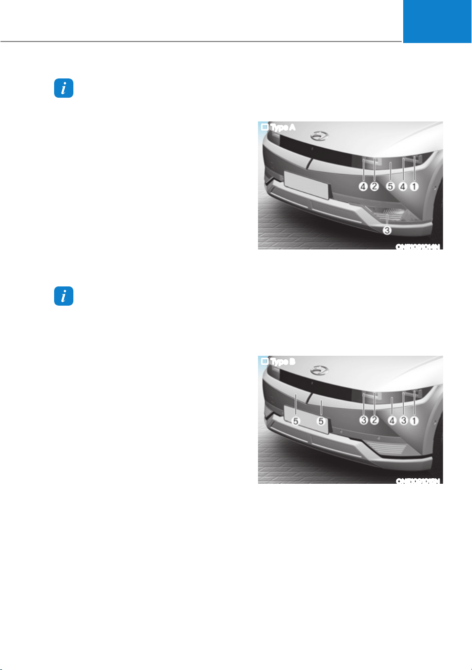
09
9-49
Information
ś A normally functioning lamp may
flicker momentarily to stabilize the
vehicle’s electrical control system.
However, if the lamp goes out after
flickering momentarily, or continues to
flicker, have the system checked by an
authorized HYUNDAI dealer.
ś The Parking lamp may not turn on
when the Parking lamp switch is turned
on, but the Parking lamp and headlamp
switch may turn on when the headlamp
switch is turned on. This may be caused
by network failure or vehicle electrical
control system malfunction. If this
occurs, have the system checked by an
authorized HYUNDAI dealer.
Information
The headlamp aiming should be adjusted
after an accident or after the headlamp
assembly is reinstalled.
Headlamp, Parking Lamp, Turn
Signal Lamp, Daytime Running
Light (DRL) Replacement
Type A
ONE1091014N
Type A
(1) Headlamp (High/Low)
(2) Headlamp (Low)
(3) Turn signal lamp (Bulb type)
(4) Parking lamp/Daytime running light
(DRL)
(5) Front side marker (LED)
Type B
ONE1091015N
Type B
(1) Headlamp (Low)
(2) Headlamp (High)
(3) Parking lamp/Daytime running light/
Turn signal lamp (LED)
(4) Front side marker (LED)
(5) Garnish hidden lighting (if equipped)

Maintenance
9-50
If the LED lamp does not operate, have
the system inspected by an authorized
HYUNDAI dealer.
The LED lamps cannot be replaced as
a single unit because it is an integrated
unit. The LED lamps has to be replaced
with the unit.
A skilled technician should check or
repair the LED lamp, for it may damage
related parts of the vehicle.
Turn signal lamp (bulb type)
1. Engage the parking brake and
disconnect the negative battery cable.
2. Remove wheel guard clips (under the
front bumper).
3. Push the wheel guard aside and
remove the bulb socket by turning it
counterclockwise.
4. Remove the bulb from the socket
by pressing it in and rotating it
counterclockwise until the tabs on the
bulb align with the slots in the socket.
Pull the bulb out of the socket.
5. Install a new bulb by inserting it into
the socket and rotating it until it locks
into place.
6. Push the socket into the assembly and
turn the socket clockwise.
7. Install the wheel guard in the reverse
order.
WARNING
ś Wear eye protection when changing
a bulb. Allow the bulb to cool down
before handling it.
ś Always handle them carefully, and
avoid scratches and abrasions. If
the bulbs are lit, avoid contact with
liquids.
ś Never touch the glass with bare
hands. Residual oil may cause the
bulb to overheat and burst when lit.
ś A bulb should be operated only when
installed in a turn signal lamp.
ś If a bulb becomes damaged or
cracked, replace it immediately and
carefully dispose of it.
ś Replacing the bulb may cause
damage to the bulb relevant parts
of the vehicle, and also may cause
injuries. To replace the turn signal
lamp, visit an authorized HYUNDAI
dealer.
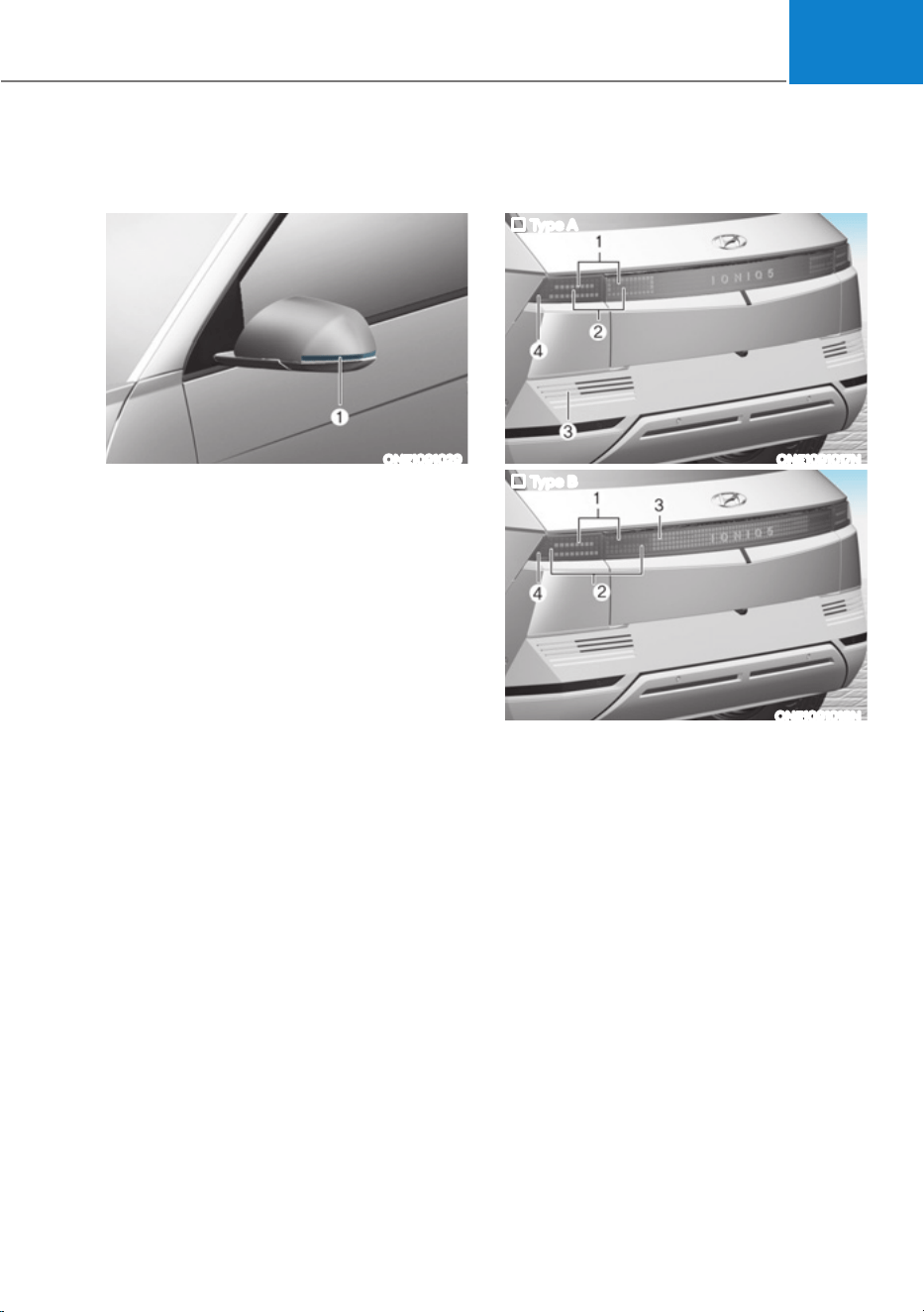
09
9-51
Side Repeater Lamp
Replacement
ONE1091029
If the LED lamp (1) does not operate,
have the system inspected by an
authorized HYUNDAI dealer.
The LED lamps cannot be replaced as
a single unit because it is an integrated
unit. The LED lamps has to be replaced
with the unit.
A skilled technician should check or
repair the LED lamp, for it may damage
related parts of the vehicle.
Rear Combination Lamp
Replacement
Type A
ONE1091017N
Type B
ONE1091018N
(1) Rear lamp/Stop lamp
(2) Stop lamp/Turn signal lamp
(3) Reverse lamp
- Type A : Bulb
- Type B : LED (if equipped)
(4) Rear side marker (LED)
If the LED lamp does not operate, have
the system inspected by an authorized
HYUNDAI dealer.
The LED lamps cannot be replaced as
a single unit because it is an integrated
unit. The LED lamps has to be replaced
with the unit.
A skilled technician should check or
repair the LED lamp, for it may damage
related parts of the vehicle.

Maintenance
9-52
Reverse lamp (bulb type)
1. Disconnect the negative battery
cable.
2. Loosen the retaining clips under the
bumper and screws on the wheel
house trim.
3. Prey trim under the bumper toward
the vehicle.
4. Remove the socket from the
assembly by turning the socket
counterclockwise until the tabs on
the socket align with the slots on the
assembly.
5. Remove the bulb by pulling it straight
out.
6. Insert a new bulb in the socket.
7. Reinstall the light assembly to the
body of the vehicle.
WARNING
ś Wear eye protection when changing
a bulb. Allow the bulb to cool down
before handling it.
ś Always handle them carefully, and
avoid scratches and abrasions. If
the bulbs are lit, avoid contact with
liquids.
ś Never touch the glass with bare
hands. Residual oil may cause the
bulb to overheat and burst when lit.
ś A bulb should be operated only when
installed in a turn signal lamp.
ś If a bulb becomes damaged or
cracked, replace it immediately and
carefully dispose of it.
ś Replacing the bulb may cause
damage to the bulb relevant parts
of the vehicle, and also may cause
injuries. To replace the turn signal
lamp, visit an authorized HYUNDAI
dealer.
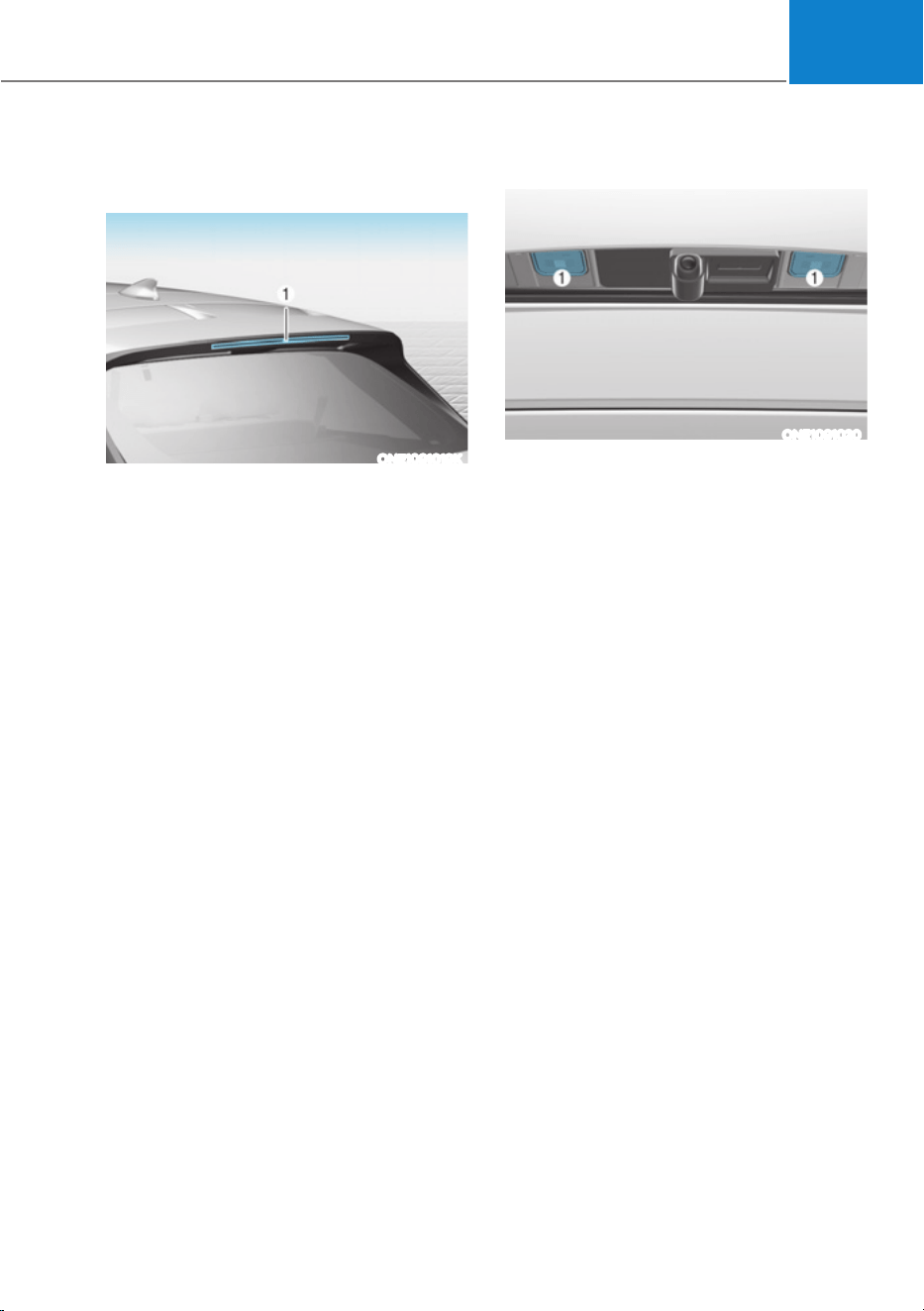
09
9-53
High Mounted Stop Lamp
Replacement
ONE1091019K
If the LED lamp (1) does not operate,
have the system inspected by an
authorized HYUNDAI dealer.
The LED lamps cannot be replaced as
a single unit because it is an integrated
unit. The LED lamps has to be replaced
with the unit.
A skilled technician should check or
repair the LED lamp, for it may damage
related parts of the vehicle
License Plate Lamp Replacement
ONE1091020
If the LED lamp (1) does not operate,
have the system inspected by an
authorized HYUNDAI dealer.
The LED lamps cannot be replaced as
a single unit because it is an integrated
unit. The LED lamps has to be replaced
with the unit.
A skilled technician should check or
repair the LED lamp, for it may damage
related parts of the vehicle.
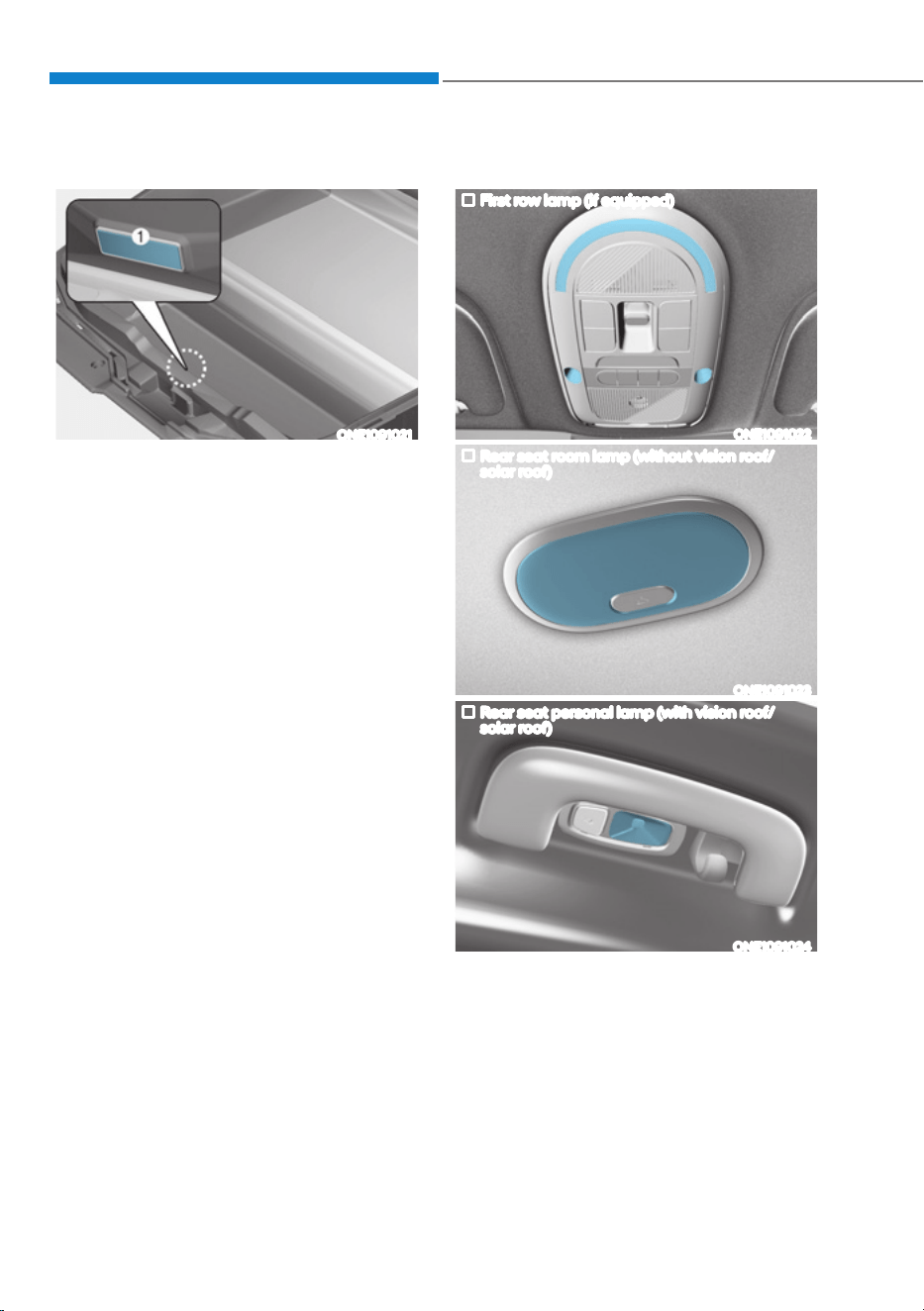
Maintenance
9-54
Front Trunk Lamp Replacement
ONE1091021
If the LED lamp (1) does not operate,
have the system inspected by an
authorized HYUNDAI dealer.
The LED lamps cannot be replaced as
a single unit because it is an integrated
unit. The LED lamps has to be replaced
with the unit.
A skilled technician should check or
repair the LED lamp, for it may damage
related parts of the vehicle.
Interior Light Replacement
First row lamp (if equipped)
ONE1091022
Rear seat room lamp (without vision roof/
solar roof)
ONE1091023
Rear seat personal lamp (with vision roof/
solar roof)
ONE1091024
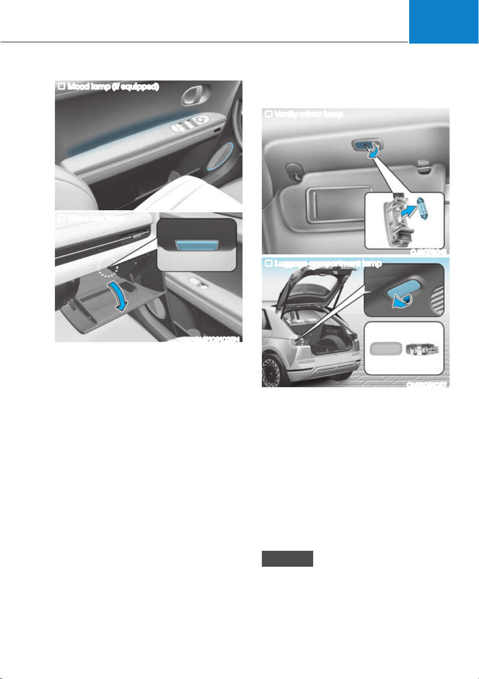
09
9-55
Mood lamp (if equipped)
ONE1091026
Glove box lamp
ONE1091025N
If the LED lamp (1) does not operate,
have the system inspected by an
authorized HYUNDAI dealer.
The LED lamps cannot be replaced as
a single unit because it is an integrated
unit. The LED lamps has to be replaced
with the unit.
A skilled technician should check or
repair the LED lamp, for it may damage
related parts of the vehicle.
Vanity mirror lamp and luggage
compartment lamp (Bulb type)
Vanity mirror lamp
OJS078041
Luggage compartment lamp
ONE1091027
1. Apply the parking brake and place the
Start/Stop button in the OFF position.
2. Turn off the lights.
3. Using a flat-head screwdriver, gently
pry the lens from the interior light
housing.
4. Remove the bulb by pulling it straight
out.
5. Insert a new bulb into the socket.
6. Align the lens tabs with the interior
light housing notches and snap the
lens into place.
NOTICE
Use care not to dirty or damaged lenses,
lens tabs, and plastic housings.

Maintenance
9-56
Exterior Care
NOTICE
If you park your vehicle near a stainless
steel sign or glass facade building, the
vehicle’s exterior plastic parts such
as a bumper, spoiler, garnish, lamp
or outside rearview mirror might be
damaged due to sunlight reflected from
the sign or building. To prevent damage
of the exterior plastic parts, you should
avoid parking in areas where light may
be reflected or use a car cover. (The
exterior plastic parts applied to your
vehicle may vary.)
Exterior general caution
It is very important to follow the label
directions when using any chemical
cleaner or polish. Read all warning and
caution statements that appear on the
label.
Finish maintenance
Washing
To help protect your vehicle’s finish from
rust and deterioration, wash it thoroughly
and frequently at least once a month
with lukewarm or cold water.
If you use your vehicle for off-road
driving, you should wash it after each
off-road trip. Pay special attention to the
removal of any accumulation of salt, dirt,
mud, and other foreign materials. Make
sure the drain holes in the lower edges
of the doors and rocker panels are kept
clear and clean.
Insects, tar, tree sap, bird droppings,
industrial pollution and similar deposits
can damage your vehicle’s finish if not
removed immediately.
Even prompt washing with plain water
may not completely remove all these
deposits. A mild soap, safe for use on
painted surfaces, should be used.
After washing, rinse the vehicle
thoroughly with lukewarm or cold water.
Do not allow soap to dry on the finish.
High-pressure washing
ś When using high-pressure washers,
make sure to maintain sufficient
distance from the vehicle.
Insufficient clearance or excessive
pressure can lead to component
damage or water penetration.
ś Do not spray the camera, sensors or
its surrounding area directly with a
high pressure washer. Shock applied
from high pressure water may cause
the device to not operate normally.
ś Do not bring the nozzle tip close to
boots (rubber or plastic covers) or
connectors as they may be damaged
if they come into contact with high
pressure water.
WARNING
After washing the vehicle, test the
brakes while driving slowly to see
if they have been affected by water
before getting on the road. If braking
performance is impaired, dry the
brakes by applying them lightly while
maintaining a slow forward speed.
APPEARANCE CARE
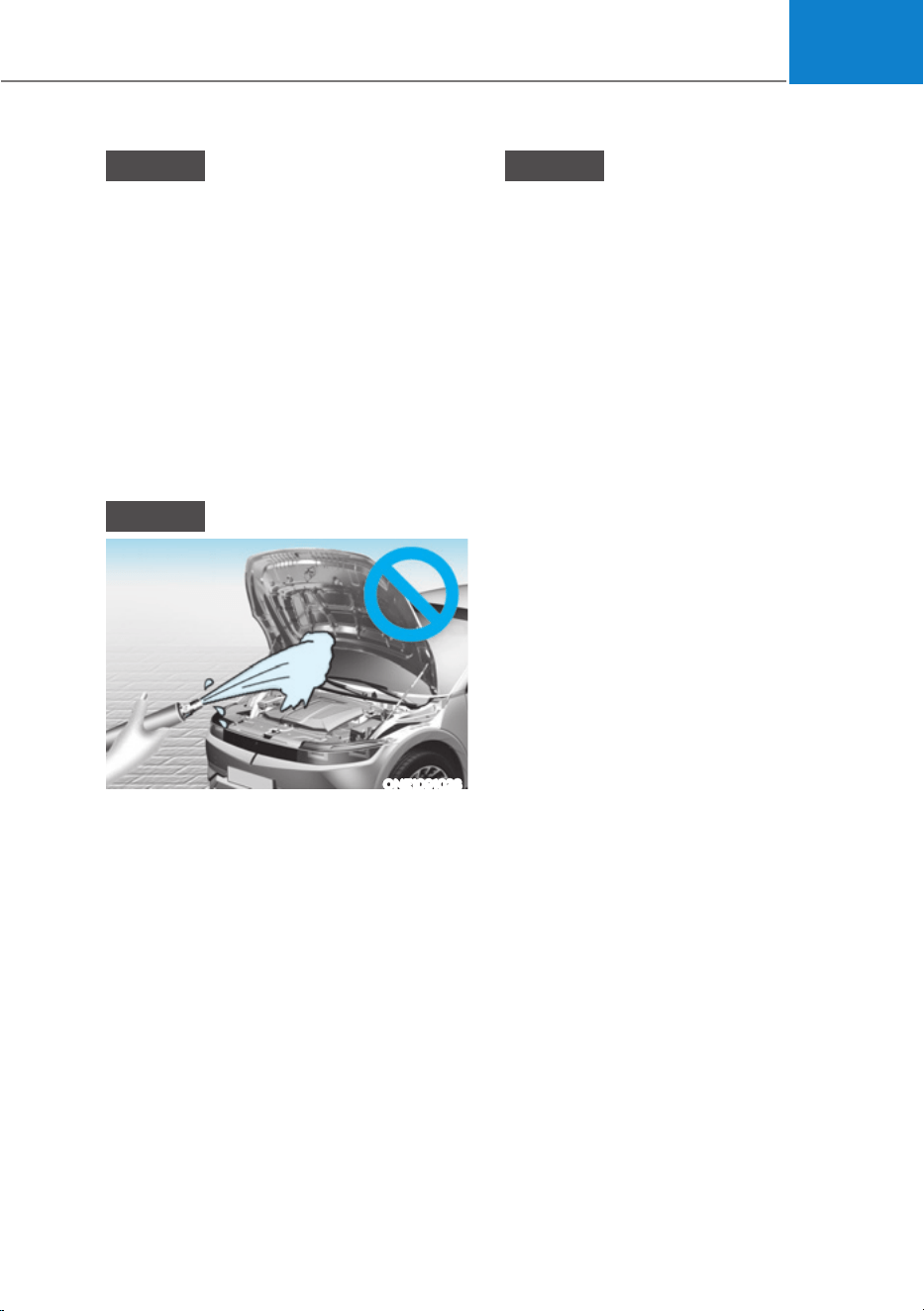
09
9-57
NOTICE
ś Do not use strong soap, chemical
detergents or hot water, and do not
wash the vehicle in direct sunlight
or when the body of the vehicle is
warm.
ś Be careful when washing the side
windows of your vehicle.
ś Especially, with high-pressure water,
water may leak through the windows
and wet the interior.
ś To prevent damage to the plastic
parts, do not clean with chemical
solvents or strong detergents.
NOTICE
ONE1091028
ś Water washing in the motor
compartment including high
pressure water washing may cause
the failure of electrical circuits
located in the vehicle compartment.
ś Never allow water or other liquids
to come in contact with electrical/
electronic components inside the
vehicle as water or other liquids may
flow in to the motor compartment
through the front trunk and damage
electrical/electronic components.
NOTICE
Matte paint finish vehicle (if equipped)
Automatic car wash which uses rotating
brushes should not be used as this can
damage the surface of your vehicle. A
steam cleaner which washes the vehicle
surface at high temperature may result
the oil to adhere and leave stains that is
difficult to remove.
Use a soft cloth (e.g. microfiber towel
or sponge) when washing your vehicle
and dry with a microfiber towel. When
you hand wash your vehicle, you should
not use a cleaner that finishes with wax.
If the vehicle surface is too dirty (sand,
dirt, dust, contaminant, etc.), clean the
surface with water before washing the
car.
Waxing
A good coat of wax is a barrier between
your paint and contaminate. Keeping
a good coat of wax on your vehicle will
help protect it.
Wax the vehicle when water will no
longer bead on the paint.
Always wash and dry the vehicle before
waxing. Use a good quality liquid or
paste wax, and follow the manufacturer’s
instructions. Wax all metal trim to protect
it and to maintain its luster.
Removing oil, tar, and similar materials
with a spot remover will usually strip the
wax from the finish. Be sure to re-wax
these areas even if the rest of the vehicle
does not yet need waxing.

Maintenance
9-58
NOTICE
ś Wiping dust or dirt off the body with
a dry cloth will scratch the finish.
ś Do not use steel wool, abrasive
cleaners, or strong detergents
containing highly alkaline or
caustic agents on chrome-plated or
anodized aluminum parts. This may
result in damage to the protective
coating and cause discoloration or
paint deterioration.
NOTICE
Matte paint finish vehicle (if equipped)
Do not use any polish protector such as
a detergent, an abrasive and a polish.
In case wax is applied, remove the wax
immediately using a silicon remover
and if any tar or tar contaminant is on
the surface use a tar remover to clean.
However, be careful not to apply too
much pressure on the painted area.
Finish damage repair
Deep scratches or stone chips in the
painted surface must be repaired
promptly. Exposed metal will quickly
rust and may develop into a major repair
expense.
NOTICE
If your vehicle is damaged and requires
any metal repair or replacement,
be sure the body shop applies anti-
corrosion materials to the parts
repaired or replaced.
NOTICE
Matte paint finish vehicle (if equipped)
In case of matte paint finish vehicles,
it is impossible to modify only the
damaged area and repair of the whole
part is necessary. If the vehicle is
damaged and painting is required, have
your vehicle maintained and repaired
by an authorized HYUNDAI dealer. Take
extreme care, as it is difficult to restore
the quality after the repair.
Bright-metal maintenance
ś To remove road tar and insects, use
a tar remover, not a scraper or other
sharp object.
ś To protect the surfaces of brightmetal
parts from corrosion, apply a coating
of wax or chrome preservative and rub
to a high luster.
ś During winter weather or in coastal
areas, cover the bright metal parts
with a heavier coating of wax or
preservative. If necessary, coat the
parts with non-corrosive petroleum
jelly or other protective compound.

09
9-59
Underbody maintenance
Corrosive materials used for ice and
snow removal and dust control may
collect on the underbody. If these
materials are not removed, accelerated
rusting can occur on underbody parts
such as the frame and floor pan, even
though they have been treated with rust
protection.
Thoroughly flush the vehicle underbody
and wheel openings with lukewarm or
cold water once a month, after off-road
driving and at the end of each winter. Pay
special attention to these areas because
it is difficult to see all the mud and dirt.
It will do more harm than good to wet
down the road grime without removing
it. The lower edges of doors, rocker
panels, and frame members have drain
holes that should not be allowed to clog
with dirt; trapped water in these areas
can cause rusting.
WARNING
After washing the vehicle, test the
brakes while driving slowly to see if
they have been affected by water. If
braking performance is impaired, dry
the brakes by applying them lightly
while maintaining a slow forward
speed.
Aluminum wheel maintenance
The aluminum wheels are coated with a
clear protective finish.
ś Do not use abrasive cleaner, polishing
compound, solvent, or wire brushes
on aluminum wheels.
ś Clean the wheel when it has cooled.
ś Use only a mild soap or neutral
detergent, and rinse thoroughly with
water. Also, clean the wheels after
driving on salted roads.
ś Do not wash the wheels with high-
speed car wash brushes.
ś Do not use any cleaners containing
acid or alkaline detergents.
Corrosion protection
Protecting your vehicle from corrosion
By using the most advanced design
and construction practices to combat
corrosion, HYUNDAI produces vehicles
of the highest quality. However, this is
only part of the job. To achieve the long-
term corrosion resistance your vehicle
can deliver, the owner’s cooperation and
assistance is also required.
Common causes of corrosion
The most common causes of corrosion
on your vehicle are:
ś Road salt, dirt and moisture that is
allowed to accumulate underneath
the vehicle.
ś Removal of paint or protective
coatings by stones, gravel, abrasion
or minor scrapes and dents which
leave unprotected metal exposed to
corrosion.

Maintenance
9-60
High-corrosion areas
If you live in an area where your vehicle is
regularly exposed to corrosive materials,
corrosion protection is particularly
important. Some of the common causes
of accelerated corrosion are road salts,
dust control chemicals, ocean air and
industrial pollution.
Moisture breeds corrosion
Moisture creates the conditions in
which corrosion is most likely to occur.
For example, corrosion is accelerated
by high humidity, particularly when
temperatures are just above freezing. In
such conditions, the corrosive material is
kept in contact with the vehicle surfaces
by moisture that is slow to evaporate.
Mud is particularly corrosive because
it is slow to dry and holds moisture in
contact with the vehicle. Although the
mud appears to be dry, it can still retain
moisture and promote corrosion.
High temperatures can also accelerate
corrosion of parts that are not properly
ventilated so the moisture can be
dispersed. For all these reasons, it is
particularly important to keep your
vehicle clean and free of mud or
accumulations of other materials. This
applies not only to the visible surfaces
but particularly to the underside of the
vehicle.
To help prevent corrosion
Keep your vehicle clean
The best way to prevent corrosion is
to keep your vehicle clean and free of
corrosive materials. Attention to the
underside of the vehicle is particularly
important.
ś If you live in a high-corrosion area —
where road salts are used, near the
ocean, areas with industrial pollution,
acid rain, etc.—, you should take extra
care to prevent corrosion. In winter,
hose off the underside of your vehicle
at least once a month and be sure to
clean the underside thoroughly when
winter is over.
ś When cleaning underneath the
vehicle, pay particular attention to the
components under the fenders and
other areas that are hidden from view.
Do a thorough job; just dampening
the accumulated mud rather than
washing it away will accelerate
corrosion rather than prevent it. Water
under high pressure and steam are
particularly effective in removing
accumulated mud and corrosive
materials.
ś When cleaning lower door panels,
rocker panels and frame members, be
sure that drain holes are kept open so
that moisture can escape and not be
trapped inside to accelerate corrosion.

09
9-61
Keep your garage dry
Don’t park your vehicle in a damp,
poorly ventilated garage. This creates
a favorable environment for corrosion.
This is particularly true if you wash your
vehicle in the garage or drive it into the
garage when it is still wet or covered with
snow, ice or mud. Even a heated garage
can contribute to corrosion unless it is
well ventilated so moisture is dispersed.
Keep paint and trim in good condition
Scratches or chips in the finish should
be covered with “touch-up” paint as
soon as possible to reduce the possibility
of corrosion. If bare metal is showing
through, the attention of a qualified body
and paint shop is recommended.
Bird droppings are highly corrosive and
may damage painted surfaces in just a
few hours. Always remove bird droppings
as soon as possible.
Interior Care
Interior general precautions
Prevent caustic solutions such as
perfume and cosmetic oil, from
contacting the interior parts because
they may cause damage or discoloration.
If they do contact the interior parts,
wipe them off immediately. See the
instructions for the proper way to clean
vehicle interior surfaces.
NOTICE
ś Never allow water or other liquids
to come in contact with electrical/
electronic components inside the
vehicle as this may damage them.
ś When cleaning leather products
(steering wheel, seats etc.), use
neutral detergents or low alcohol
content solutions. If you use high
alcohol content solutions or acid/
alkaline detergents, the color of the
leather may fade or the surface may
get stripped off.
Cleaning the upholstery and interior
trim
Vehicle interior surfaces (if equipped)
Remove dust and loose dirt from interior
surfaces with a whisk broom or a vacuum
cleaner. If necessary, clean interior
surfaces with a mixture of warm water
and mild non-detergent cleaner (test all
cleaners on a concealed area before use).
Fabric (if equipped)
Remove dust and loose dirt from
fabric with a whisk broom or vacuum
cleaner. Clean with a mild soap solution
recommended for upholstery or carpets.
Remove fresh spots immediately with
a fabric spot cleaner. If fresh spots do
not receive immediate attention, the
fabric can be stained and its color can be
affected. Also, its fire-resistant properties
can be reduced if the material is not
properly maintained.

Maintenance
9-62
NOTICE
Using anything but recommended
cleaners and procedures may affect the
fabric’s appearance and fire-resistant
properties.
Leather (if equipped)
ś Features of seat leather
- Leather is made from the outer skin
of an animal, which goes through a
special process to be available for
use. Since it is a natural product,
each part differs in thickness or
density.
Wrinkles may appear as a natural
result of stretching and shrinking
depending on the temperature and
humidity.
- The seat is made of stretchable
fabric to improve comfort.
- The parts contacting the body are
curved and the side supporting
area is high which provides driving
comfort and stability.
- Wrinkles may appear naturally
from usage. It is not a fault of the
products.
NOTICE
ś Wrinkles or abrasions which appear
naturally from usage are not covered
by warranty.
ś Belts with metallic accessories,
zippers or keys inside the back
pocket may damage the seat fabric.
ś Make sure not to wet the seat. It may
change the nature of natural leather.
ś Jeans or clothes which could bleach
may contaminate the surface of the
seat covering fabric.
ś Caring for the leather seats
- Vacuum the seat periodically to
remove dust and sand on the seat. It
will prevent abrasion or damage of
the leather and maintain its quality.
- Wipe the natural leather seat cover
often with dry or soft cloth.
- Use of proper leather protector may
prevent abrasion of the cover and
helps maintain the color. Be sure to
read the instructions and consult
a specialist when using leather
coating or protective agent.
- Light colored (beige, cream beige)
leather is easily contaminated and
the stain is noticeable. Clean the
seats frequently.
- Avoid wiping with wet cloth. It may
cause the surface to crack.
ś Cleaning the leather seats
- Remove all contaminations
instantly. Refer to instructions below
for removal of each contaminant.
- Cosmetic products (sunscreen,
foundation, etc.)
Apply cleansing cream on a cloth
and wipe the contaminated spot.
Wipe off the cream with a wet cloth
and remove water with a dry cloth.
- Beverages (coffee, soft drink, etc.)
Apply a small amount of neutral
detergent and wipe until
contaminations do not smear.
- Oil
Remove oil instantly with
absorbable cloth and wipe with
stain remover used only for natural
leather.
- Chewing gum
Harden the gum with ice and
remove gradually.

09
9-63
Cleaning the seat belt webbing
Clean the belt webbing with any
mild soap solution recommended for
cleaning upholstery or carpet. Follow
the instructions provided with the soap.
Do not bleach or re-dye the webbing
because this may weaken the seat belt.
Cleaning the interior window glass
If the interior glass surfaces of the
vehicle become fogged (that is, covered
with an oily, greasy or waxy film), they
should be cleaned with glass cleaner.
Follow the directions on the glass cleaner
container.
NOTICE
Do not scrape or scratch the inside of
the rear window. This may result in
damage to the rear window defroster
grid.

Maintenance
9-64
CALIFORNIA PERCHLORATE NOTICE
Perchlorate Material-special handling may apply, See: www.dtsc.ca.gov/perchlorate.
Notice to California Vehicle Dismantlers: Perchlorate containing materials, such as
air bag inflators, seatbelt pretensioners and keyless remote entry batteries, must be
disposed of according to Title 22 California Code of Regulations Section 67384.10 (a).