Loading ...
Loading ...
Loading ...
Part number 550-100-400/0119
95
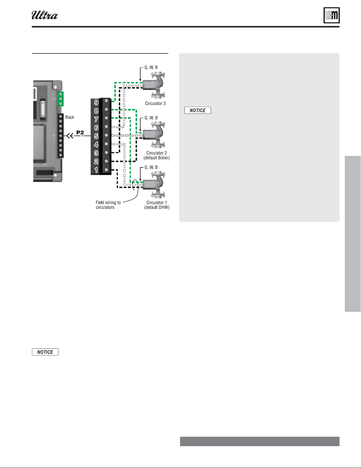
Field wiring — advanced (continued)
during DHW heating. To use factory default settings,
make sure to connect the DHW circulator to terminals 1,
4 and 7, as below:
4. The factory
for space heating is designed for
fi nned-tube baseboard, and set up to activate Circula-
tor 2 and Circulator 3 on a call for heat. Connect the
boiler circulator to terminals 2, 5 and 8 and the system
circulator to terminals 3, 6 and 9 to use these default
settings.
5. Make sure the U-Control is programmed to activate
the system circulator when it is required (during space
heating, for instance).
Thermostats & DHW tank
temperature control connections
Use isolating relays if using 3-wire zone valves
to avoid damage and nuisance problems due
to stray voltage.
1. The U-Control allows operation by up to three different
heating systems.
2. The factory default confi guration is for “heat demand 1”
to be DHW and “heat demand 2” to be space heating.
For factory default operation:
a. Connect the space heating thermostat to terminal
strip P15, terminals 1 and 2 to use the default setup.
b. Connect the DHW tank temperature control across
terminal strip P11, terminals 4 and 5 to use the
default setup.
3. Install thermostats on inside walls away from the infl uences of
drafts, hot or cold water pipes, lighting fi xtures, television, sun
rays, or fi replaces.
4. Thermostat anticipator (if applicable):
If connected directly to the boiler, set anticipator for 0.1 amps.
If connected to relays or other devices, set to match total elec-
trical power requirements of connected devices. See device
manufacturers’ specifi cations and the thermostat instructions
for details.
Low water cut-offs
1. See the on this page regarding internal low water protec-
tion provided by the U-Control.
2. When an external low water cut-off is installed, connect as shown
in the U-Control wiring diagrams ( Figure 111, page 96Fig-
ure 112, page 97 ).
3. When possible, use the Weil-McLain Ultra low water cut-off kit
listed in the back of this manual. It includes a probe-type low water
cut-off and provides a simple harness connection for the wiring.
The U-Control m odule provides internal
low water protection
1. The U-Control and internal sensors in the Ultra boiler provide
both temperature control and low water protection (using
temperature senors), as explained below:
The U-Control module uses temperature sensors to
provide both high limit protection and modulating
temperature control.
The U-Control module also provides
by using a dual sensor to monitor the
temperature of the heat exchanger. [The U-Control
constantly monitors the sensor signals to ensure
they are within 10 °F of one another. If the sensor
difference exceeds 10 °F, the boiler is shutdown on
automatic reset.] This method is accepted in many
areas as meeting the requirement for a low water
cut-off.
Some codes or jurisdictions may require additional
external controls for high limit and/or low water
cutoff protection. Follow the guidelines in this
manual to install additional controls when required.
Figure 110 irin to circulators
®
Series 4
gas-fired water boiler — Boiler Manual
Loading ...
Loading ...
Loading ...