
Safety • AssembJy • Operation • Adjustment • Maintenance • TroubJeshooting • Warranty
A OR'S MANUAL
Transmatic Lawn Tractor- Models 760=779
iMPORTANT
READ SAFETY RULES AND iNSTRUCTiONS CAREFULLY BEFORE OPERATION
Warning: This unitis equippedwithan internalcombustionengineandshouldnot beusedon or nearany unimprovedforest-covered,brush-
coveredor grass-coveredland unlessthe engine'sexhaustsystemis equippedwitha sparkarrestermeetingapplicablelocalor state laws (if any).
If a sparkarresteris used,it shouldbe maintainedin effectiveworkingorderby the operator.Inthe Stateof Californiathe aboveis requiredbylaw
(Section4442of the CaliforniaPublicResourcesCode). Otherstatesmayhavesimilarlaws.Federallawsapplyon federallands.A sparkarrester
for the muffleris availablethroughyournearestengineauthorizedservicedealeror contactthe servicedepartment,RO. Box361131Cleveland,
Ohio44136-0019.
FORMNO.769-01598A
PRINTEDIN U.S.A. MTD LLC, P.O. BOX 361131 CLEVELAND, OHiO 44136=0019 10/11/2005

This Operator's Manual is an important part of your new lawn tractor, it will help you assemble,
prepare and maintain the unit for best performance. Please read and understand what it says.
Table of Contents
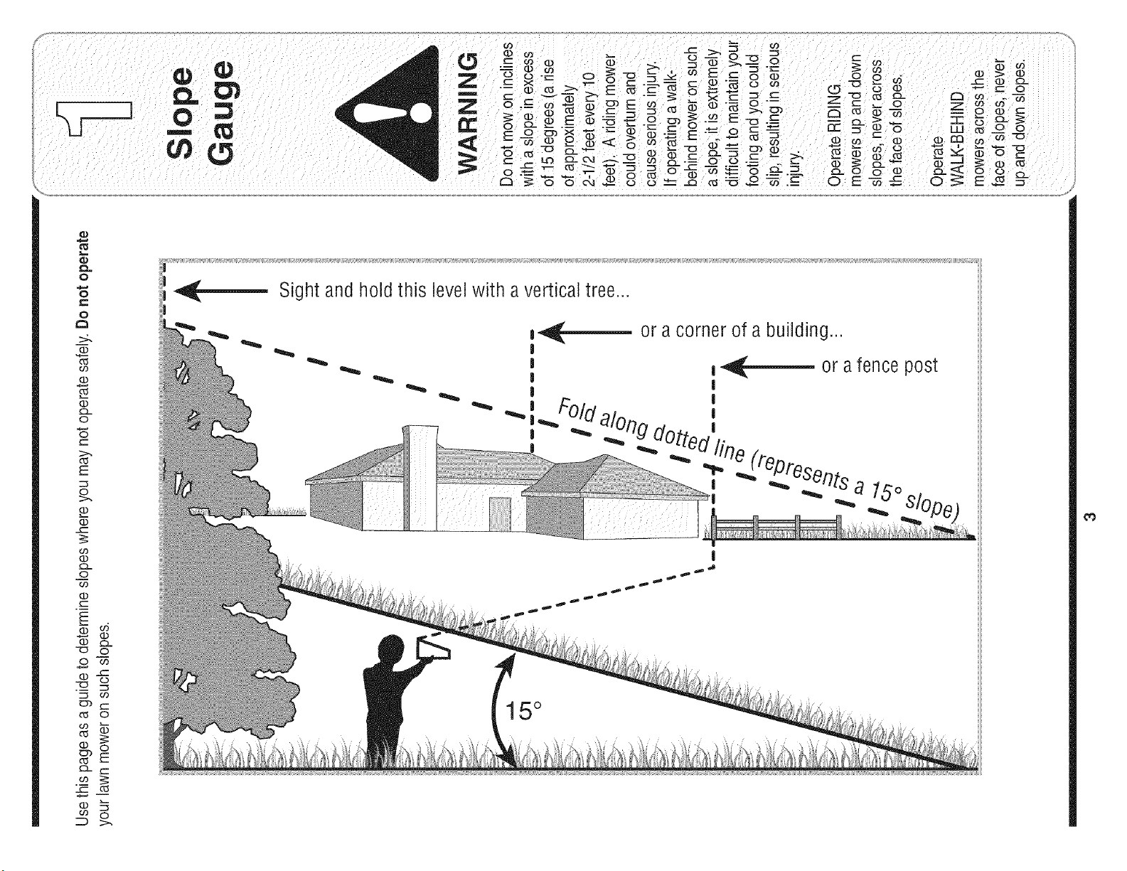
Slope Gauge ....................................................... 3
Safe Operation Practices ................................... 4
Setting Up Your Lawn Tractor ............................ 8
Operating Your Lawn Tractor ........................... 12
Adjusting Your Lawn Tractor ............................ 20
Maintaining Your Lawn Tractor ........................ 22
Off-Season Storage / Attachments ................. 28
Safety Labels .................................................... 29
Trouble Shooting .............................................. 30
Warranty .............................................. Back Page
Finding and Recording Model Number
BEFOREYOU STARTASSEMBLING
YOUR NEW EQUIPMENT,
please locatethe model plate on the equipment and copy the
information to the sample model plate providedto the right.
You can locate the model plate by looking beneathe the seat.
This information will be necessary to use the manufacturer's
web site and/or obtain assistance from the Customer Support
Department or an authorized service dealer.
F
Model Number
®
_ www.mtdproducts,com
Serial Number
MTD LLC
P.O. BOX 361131
CLEVELAND, OH 44136
330=220=4683
800=800=731 0
Customer Support
Please do NOTreturn the unit to the retailer from which it was
purchased, without first contacting Customer Support.
If you have difficulty assembling this product or have any questions regardingthe controls, operation, or maintenanceof this
unit, you can seek help from the experts. Choose from the options below:
1. Visit mtdproducts.com. Click on the Service & Support menu option.
2. Phonea Customer Support Representative at (800) 800-7310.
3. The engine manufacturer is responsiblefor all engine-relatedissues with regardsto performance, power-rating,specifica-
tions, warranty and service. Please refer to the engine manufacturer'sOwner's/Operator's Manual, packed separatelywith
your unit, for more information.
Product Registration
?dw_:_ Pebz_
2
O
O
o
03
(b
£1.
O
CZ
(_
E
o>.
o
(D
03
(b
CL
o
03
(D
CZ
O
"O O
o_
'_5
-t2
03
Ob CZ
(_ O
(b O
Ob
E
Cz
o
co O
ZD >-
Sight and hold this level with a vertical tree...
ii
_---- or a corner of a building...
_-- or a fence post
I
|
|
I
_ _ _rlts a 15°
|
15 °
_0
WARNING: Engine Exhaust,some of its constituents, and certain vehicle compo-
) I Jill nents conta n or em t chem ca s knownto State of Ca forn a to cause cancer and
birth defects or other reproductiveharm.
DANGER: This machine was built to be operated according to the rules for safe operation in this
manual. As with any type of power equipment, carelessness or error on the part of the operator can
result in serious injury. This machine is capable of amputating hands and feet and throwing objects.
Failureto observe the following safety instructions could result in serious injury or death.
'WARNING
' This symbol points
out important safety
instructionswhich, if
i not followed, could
endangerthe personal
i safety and/or property
i of yourself and others.
i Read and follow all
I instructions in this man-
i ual before attempting to
i operate this machine.
Failureto comply with
these instructions may
I result in personal injury.
i When you see this
_sy bl
m o.
I HEED ITSWARNING
Your
Responsibility
i Restrictthe use
of this cower machine
i to persons who read,
understand
' and follow the warnings
and instructions
in this manual
Children
1. Tragicaccidentscan occurif the operatoris not
alert tothe presenceof children.Childrenareoften
attractedto the machineandthe mowingactivity.
Theydo not understandthe dangers.Neverassume
thatchildrenwill remainwhereyou last saw them.
a. Keepchildrenout of the mowingarea and in
watchfulcare of a responsibleadult otherthan
the operator.
b. Bealert andturn machineoff if a childenters
the area.
c. Beforeandwhile backing,lookbehindand
downfor smallchildren.
d. Nevercarrychildren,evenwiththe blade(s)
shutoff.They mayfalloffandbeseriously
injuredor interferewith safemachineoperation.
e. Useextremecarewhenapproachingblind
corners,doorways,shrubs,treesor other
objectsthat mayblock yourvisionof a child
who mayruninto the machine.
f. To avoid back-overaccidents, always
disengagethe cutting blade(s) before
shifting into Reverse.If equipped,the
"Reverse Caution Mode"should not be
used when children or othersare around.
g. Keepchildrenaway from hotor running
engines.Theycansufferburnsfroma hot
muffler.
h. Removekeywhen machineis unattendedto
preventunauthorizedoperation.
2. Neverallowchildrenunder 14years old to operate
the machine.Children14years old and overshould
readandunderstandthe operationinstructionsand
safetyrules inthis manualandshouldbe trainedand
supervisedbya parent.
Operation
Safe Handling of Gasoline:
1. Toavoid personalinjuryor propertydamage use
extremecare in handlinggasoline. Gasolineis
extremelyflammable and the vapors areexplo-
sive. Seriouspersonalinjurycanoccurwhengasoline
is spilledon yourselfor yourclotheswhichcan ignite.
Washyourskin and changeclothesimmediately.
a. Useonlyan approvedgasolinecontainer.
b. Neverfill containersinsidea vehicleor ona
truckor trailerbedwitha plasticliner.Always
placecontainerson the groundawayfrom
yourvehiclebeforefilling.
c. When practical,removegas-powered
equipmentfromthe truck ortrailerand refuelit
onthe ground.If this is notpossible,then
refuelsuch equipmenton a trailerwith a
portablecontainer,ratherthan from a gasoline
dispensernozzle.
d. Keepthe nozzlein contactwith the rimof
the fueltank or containeropeningat all
timesuntilfuelingis complete.Donot usea
nozzlelock-opendevice.
e. Extinguishall cigarettes,cigars,pipesand
othersourcesof ignition.
f. Neverfuel machineindoors.
g. Neverremovegas cap oraddfuel whilethe
engineis hot or running.Allowengineto cool
at leasttwominutesbeforerefueling.
h. Neveroverfill fuel tank.Fill tank to nomore
thanY2inchbelowbottomof filler neckto
allowspacefor fuel expansion.
i. Replacegasolinecapand tightensecurely.
j. If gasolineis spilled,wipe it off the engine
andequipment.Moveunitto anotherarea.
Wait5 minutesbeforestartingthe engine.
k. To reducefire hazards,keepmachinefreeof
grass,leaves,orother debrisbuild-up.Clean
upoil or fuel spillageand removeany fuel
soakeddebris.
I. Neverstorethe machineorfuel container
insidewherethere is anopenflame,spark
or pilotlightas on awaterheater,space
heater,furnace,clothesdryeror othergas
appliances.
m. Allowa machineto cool at least five minutes
beforestoring.
4
GeneralOperation: 14.Watchfor trafficwhenoperatingnearor crossing
1. Read,understand,andfollowall instructionsonthe
machineandinthe manual(s)beforeattemptingto
assembleand operate.Keepthis manualina safe
placefor future and regularreferenceand forordering
replacementparts.
2. Befamiliarwithall controlsandtheirproperoperation.
Knowhow to stopthe machineand disengagethem
quickly.
3. Neverallowchildrenunder14yearsold to operate
this machine.Children14yearsold and overshould
readandunderstandthe operationinstructionsand
safetyrulesin thismanualand shouldbetrainedand
supervisedby a parent.
4. Neverallowadults to operatethis machinewithout
properinstruction.
5. To helpavoid bladecontactora thrownobjectinjury,
keepbystanders,helpers,childrenand petsat least
75 feetfrom the machinewhileit is inoperation.Stop
machineif anyoneentersthe area.
6. Thoroughlyinspectthearea wherethe equipmentis to
beused.Removeallstones,sticks,wire,bones,toys,
andotherforeignobjectswhichcould be pickedup
andthrownbythe blade(s).Thrownobjectscancause
seriouspersonalinjury.
7. Planyourmowingpatternto avoiddischargeof
materialtowardroads,sidewalks,bystandersandthe
like.Also,avoiddischargingmaterialagainsta wall or
obstructionwhichmaycausedischargedmaterialto
ricochetback towardthe operator.
8. Alwayswearsafety glassesor safetygogglesduring
operationand while performingan adjustmentor
repairto protectyour eyes.Thrownobjectswhich
ricochetcan causeseriousinjuryto the eyes.
9. Wearsturdy,rough-soledworkshoesandclose-fitting
slacksandshirts.Loosefittingclothesand jewelry
can becaughtinmovableparts.Neveroperatethis
machinein barefeet or sandals.
10.Be awareof the mowerandattachmentdischarge
directionanddo notpoint it at anyone.Do notoperate
the mowerwithoutthe dischargecoveror entiregrass
catcherin itsproperplace.
11.Do notput handsor feetnearrotatingpartsor under
the cuttingdeck.Contactwiththe blade(s)can
amputatehandsandfeet.
12.Amissingor damageddischargecovercan cause
bladecontactor thrownobject injuries.
13.Stoptheblade(s)whencrossinggraveldrives,walks,
or roadsandwhilenot cuttinggrass.
roadways.Thismachineis not intendedfor useon
anypublic roadway.
15.Do notoperatethe machinewhileunderthe influ-
enceof alcoholordrugs.
16.Mowonly in daylightor good artificiallight.
17.Nevercarry passengers.
18.Disengageblade(s)beforeshiftinginto reverse.
Backupslowly.Alwayslookdownand behind before
andwhilebackingto avoida back-overaccident. 'r'_'----"a_'---_,,,_pe r_ | o r_
19.Slowdownbeforeturning.Operatethe machine
smoothly.Avoiderraticoperationandexcessive
speed. P actices
20.Disengageblade(s),set parkingbrake,stopengine r
andwaituntiltheblade(s)cometoacompletestop
beforeremovinggrasscatcher,emptyinggrass,
uncloggingchute,removingany grassor debris,or
makinganyadjustments.
21.Neverleavea runningmachineunattended.Always
turnoff blade(s),placetransmissionin neutral,set
parkingbrake,stop engineand removekeybefore
dismounting.
22.Useextracare whenloadingor unloadingthe
machineintoa traileror truck. This unitshould not
bedrivenup or downramp(s),becausethe unit
couldtip over,causingseriouspersonalinjury.The
unit mustbe pushedmanuallyonramp(s)to loador
unloadproperly.
23.Mufflerandenginebecomehotand can causea
burn.Do nottouch.
24.Checkoverheadclearancescarefullybeforedriving
underlowhangingtreebranches,wires,dooropen-
ingsetc., wheretheoperatormaybe struckor pulled
fromthe unit,whichcouldresult in seriousinjury.
25.Disengageallattachmentclutches,depressthe
brakepedalcompletelyand shift into neutralbefore
attemptingto startengine.
26.Yourmachineis designedto cutnormalresidential
grassof aheightno morethan 10".Do notattemptto
mowthroughunusuallytall, dry grass (e.g.,pasture)
or pilesof dry leaves.Dry grass or leavesmay
contactthe engineexhaustand/orbuildup onthe
mowerdeckpresentinga potentialfire hazard.
27.Use onlyaccessoriesandattachmentsapprovedfor
thismachineby the machinemanufacturer.Read,
understandandfollowall instructionsprovidedwith
the approvedaccessoryor attachment.
28.Dataindicatesthat operators,age60 yearsand
above,areinvolvedin a largepercentageof riding
mower-relatedinjuries.Theseoperatorsshould
evaluatetheirability to operatetheriding mower
safelyenoughto protectthemselvesandothersfrom
seriousinjury.
29.If situationsoccurwhicharenot coveredinthis
manual,usecareandgoodjudgment.Contactyour
customerservicerepresentativefor assistance, of this power machine
to persons who read.
understand
and follow the warnings
and instructions
in this manual
WARNING
This symbol points
out important safety
instructions which, if
not followed, could
endanger the personal
safety and/or property
of yourself and others.
Readand follow all
instructions in this man-
ual before attempting to
operatethis machine.
Failureto comply with
these instructionsmay
'esult in personal injury.
When you see this
symbol.
HEED ITS WARNING
Your
Responsibil ity
Restrictthe use
\
5
S ope Operat on DoNor
Slopesare a majorfactorrelatedto loss of controland 1. Do notturn on slopes unlessnecessary;then,turn
out mportant safety
instruct!ons which, !f
not followed, could
endanger the personal
safety and!or property
I
of yourself and others,
Readand follow all
_nstruct!ons_nth_sman-
ual before attempting to
operate this machine
l l
Fa ure to compy wth
these instructions may
result
in persona injury.
When you see this
i l
tip-overaccidentswhichcan resultin severeinjury or
death.All slopesrequireextracaution.Ifyou cannot
backupthe slopeor if youfeel uneasyon it, do notmow
it.
Foryour safety,usethe slopegaugeincludedas partof
thismanualto measureslopesbeforeoperatingthis unit
ona slopedor hillyarea.If the slopeis greaterthan 15
degreesas shownon the slopegauge,do notoperate
thisunit onthatareaorseriousinjurycouldresult.
Do:
1. Mowup and downslopes,notacross.Exercise
extremecautionwhenchangingdirectionon slopes.
2. Watchfor holes,ruts,bumps,rocks,or other hidden
objects.Uneventerraincouldoverturnthe machine.
Tallgrasscan hide obstacles.
3. Useslow speed.Choosea low enoughspeed
settingso that youwill not haveto stop or shift while
onthe slope.Tiresmaylosetractiononslopeseven
thoughthe brakesare functioningproperly.Always
keepmachinein gear whengoingdownslopes to
takeadvantageof enginebrakingaction.
4. Followthe manufacturer'srecommendationsfor
wheelweightsorcounterweightsto improvestability.
5. Useextra carewithgrasscatchersor otherat-
tachments.Thesecanchangethe stabilityof the
machine.
6. Keepall movementon theslopesslowandgradual.
Do not makesuddenchangesin speedor direction.
Rapidengagementor brakingcouldcausethe front
of the machineto liftand rapidlyflip overbackwards
whichcouldcause seriousinjury.
7. Avoidstartingor stoppingon a slope.If tires lose
traction,disengagethe blade(s)andproceedslowly
straightdownthe slope.
slowlyand graduallydownhill,if possible.
2. Do not mowneardrop-offs,ditchesor embankments.
The mowercouldsuddenlyturnoverif awheel is over
the edgeof acliff,ditch,or if anedgecavesin.
3. Do nottry to stabilizethe machineby puttingyourfoot
onthe ground.
4. Do not usea grasscatcheronsteepslopes.
5. Do not mowonwet grass.Reducedtractioncould
causesliding.
6. Do notshift to neutraland coastdownhill.Over-speed-
ingmaycausethe operatorto lose controlof the
machineresultingin seriousinjuryordeath.
7. Do nottow heavypull behindattachments(e.g.loaded
dumpcart, lawnroller,etc.)on slopesgreaterthan
5 degrees.Whengoingdown hill,the extra weight
tendsto pushthetractorand maycauseyou to loose
control.(e.g. tractormayspeedup, brakingandsteer-
ingabilityarereduced,attachmentmayjack-knifeand
causetractorto overturn).
Towing:
1. Towonlywitha machinethat hasa hitchdesignedfor
towing.Do not attachtowedequipmentexceptat the
hitchpoint.
2. Followthe manufacturersrecommendationfor weight
limitsfor towedequipmentand towingon slopes.
3. Neverallowchildrenor othersin or on towedequip-
ment.
4. Onslopes,theweight of thetowedequipmentmay
causelossof tractionand loss of control.
5. Travelslowlyandallowextradistanceto stop.
6. Do notshift to neutraland coastdownhill.
symbol
l !
HEED ITS WARNING
l
l
Your
Responslbdaty
Restnctthe use
of this powermachine
to persons wno reae,
andfollowthewarn,ngs
instructions
in this manual
6
Service
1. Neverrun anengineindoorsor ina poorlyventilated
area. Engineexhaustcontainscarbonmonoxide,an
odorless,and deadlygas.
2. Beforecleaning,repairing,or inspecting,makecertain
the blade(s)and all movingpartshavestopped.
Disconnectthe sparkplugwireand groundagainstthe
engineto preventunintendedstarting.
3. Periodicallycheckto make surethe bladescome to
completestop withinapproximately(5) fiveseconds
afteroperatingthe bladedisengagementcontrol.Ifthe
bladesdo notstop within thethis time frame,your unit
shouldbe servicedprofessionallyby anauthorized
MTDServiceDealer.
4. Checkbrakeoperationfrequentlyas it is subjectedto
wearduring normaloperation.Adjustandserviceas
required.
5. Checkthe blade(s)and enginemountingbolts at
frequentintervalsfor propertightness.Also,visually
inspectblade(s)for damage(e.g.,excessivewear,
bent,cracked). Replacethe blade(s)with theoriginal
equipmentmanufacturer's(O.E.M.)blade(s)only,
listedin this manual."Useof partswhichdonot meet
the originalequipmentspecificationsmayleadto
improperperformanceandcompromisesafety!"
6. Mowerbladesare sharp.Wrapthe bladeor wear
gloves,and useextracautionwhenservicingthem.
7. Keepall nuts,bolts,and screwstight tobe surethe
equipmentis insafeworkingcondition.
8. Nevertamperwiththe safetyinterlocksystemor other
safetydevices.Checktheir properoperationregularly.
9. Afterstrikinga foreignobject,stop the engine,
disconnectthe sparkplugwire(s)and groundagainst
the engine.Thoroughlyinspectthe machinefor any
damage.Repairthe damagebeforestartingand
operating.
10.Neverattemptto makeadjustmentsor repairsto the
machinewhile theengine is running.
11.Grasscatchercomponentsandthe discharge
coveraresubjectto wearanddamagewhichcould
exposemovingpartsor allowobjectsto be thrown.
Forsafety protection,frequentlycheckcomponents
andreplaceimmediatelywith originalequipment
manufacturer's(O.E.M.)partsonly,listed in this
manual."Useof partswhich do notmeet theoriginal
equipmentspecificationsmayleadto improper
performanceandcompromisesafety!"
12.Do notchangethe enginegovernorsettingsor
over-speedthe engine.The governorcontrolsthe
maximumsafeoperatingspeedof theengine.
13.Maintainor replacesafety and instructionlabels,as
necessary.
14.Observeproperdisposallawsand regulationsfor
gas,oil,etc. to protecttheenvironment.
This symbol points
out important safety
instructions which• if
not followed, could
endanger the personal
safety and/or property
of yourself and others,
Read and follow all
instructions in this man-
ual before attempting to
operatethis machine.
Failureto comply with
these instructions may
result in personal injury.
When you see this
symbol.
HEED ITS WARNING
Your
Responsibility
Restrictthe use
of this power machine
to persons who read
unaerstand
and follow the warnings
and instructions
in this manual
\
7
f" "-, NOTE Ths OperatorsManua coversa rangeof product
( ......
f _"'_ "_ _uhh_r Rnnt j specifications for various models. Characteristics and fea-
i i |uu_/ LJUUk
--r J _ i i I turesdlscussedand/orlllustratedlnths manualmaynot
r-q"-_ I ._ _ i beapplicableto all models.MTDLLC reservesthe right
k,. _ j _/ to changeproduct specifications,designsand equipment
/ .......
''" "" _ _ i w,thoutnot,ceand w,thout,ncurr,ng obl,gat,on.
Attaching the Battery Cables
Your Law
NOTE:Somemodelsareshippedwith the batterycables
a readyconnected
Tractor
NOTE:The positivebatteryterminalis markedPos. (+).
WARNING
i
Use extreme care
l
when handl!ng
gasoline. Gasoline is
extremely flammable
and the vapors are
explosive: Never fuel
machine indoors
, ,
or while the engine
is hot or running,
Extinguish cigarettes,
cigars pipes and
other sources Of
NOTE: This Qperators
Manual Coversa range
of product specifications
for var ous mode s
" d
Characteristics an
featuresdiscussed _
and/or ustrated n
i
this manual maTnot be
applicable to al! models,
MTD LLC reservesthe
right to change product
specifications designs
and equipment without
notice and w_thoutrecur-
The negativebatteryterminalis markedNeg. (-).
Figure 1
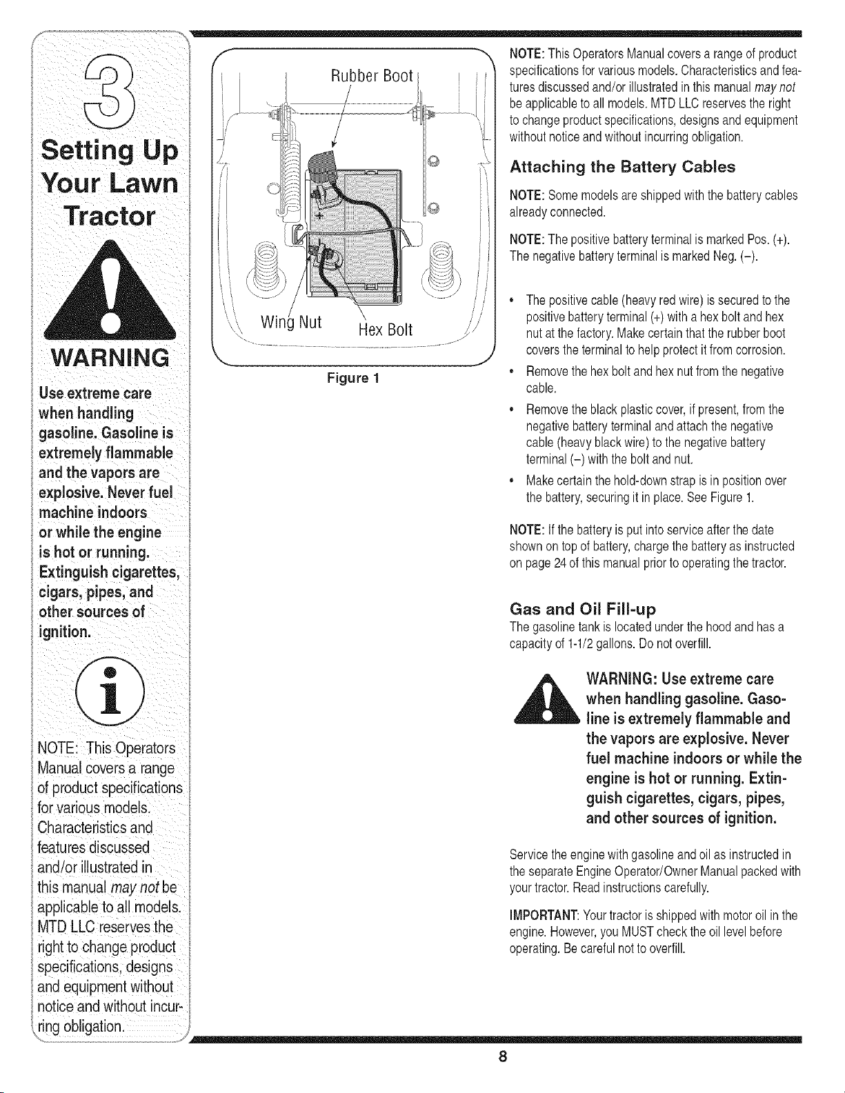
• Thepositivecable(heavyredwire) is securedto the
positivebatteryterminal(+)with a hexbolt and hex
nut at thefactory.Makecertainthatthe rubberboot
coversthe terminalto help protectit fromcorrosion.
• Removethehex bolt and hexnut fromthe negative
cable.
• Removetheblack plasticcover,if present,fromthe
negativebatteryterminaland attachthe negative
cable(heavyblack wire)to the negativebattery
terminal(-) with the bolt and nut.
• Makecertain thehold-downstrap is in positionover
the battery,securingit inplace.SeeFigure1.
NOTE:If the batteryis putinto serviceafterthe date
shownontop of battery,chargethe batteryas instructed
on page24 of this manualpriorto operatingthe tractor.
Gas and Oil Fill-up
Thegasolinetankislocatedunderthehood and hasa
capacityof 1-1/2gallons. Do notoverfill.
WARNING: Use extreme care
when handling gasoline. Gaso-
line is extremely flammable and
the vapors are explosive. Never
fuel machine indoors or while the
engine is hot or running. Extin-
guish cigarettes, cigars, pipes,
and other sources of ignition.
Servicethe enginewithgasolineand oil as instructedin
the separateEngineOperator/OwnerManualpackedwith
yourtractor.Readinstructionscarefully.
IMPORTANT:Yourtractoris shippedwith motoroil inthe
engine.However,you MUSTcheckthe oil levelbefore
operating.Becarefulnotto overfill.
8
Shipping Brace Removal
WARNING: Make sure the riding
mower's engine is off, remove the
ignition key, and set the parking
brake before removingthe ship-
ping brace.
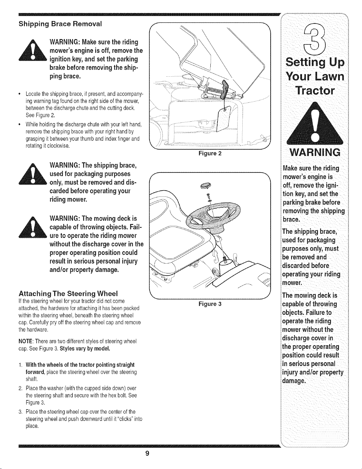
= Locatethe shippingbrace,if present,and accompany-
ingwarningtagfoundon the rightside of the mower,
betweenthe dischargechuteandthe cuttingdeck.
SeeFigure2.
,, While holdingthe dischargechutewith yourleft hand,
removetheshippingbracewithyourright handby
graspingit betweenyourthumbandindexfingerand
rotatingit clockwise.
li
Figure 2
WARNING
WARNING: The shipping brace,
used for packaging purposes
only, must be removed and dis-
carded before operating your
riding mower.
WARNING: The mowing deck is
capable of throwing objects. Fail-
ure to operate the riding mower
without the discharge cover in the
proper operating position could
result in serious personal injury
and/or property damage.
Attaching The Steering Wheel
If the steeringwheelfor yourtractordid notcome
attached,the hardwarefor attachingit hasbeenpacked
withinthe steeringwheel,beneaththe steeringwheel
cap.Carefullypry off thesteeringwheelcapand remove
the hardware.
NOTE:Therearetwodifferentstylesof steeringwheel
cap.SeeFigure3. Styles vary by model,
1. With the wheelsof the tractor pointing straight
forward, placethe steeringwheeloverthe steering
shaft.
2. Placethe washer(with thecuppedside down)over
the steeringshaftand securewith the hex bolt. See
Figure3.
3. Placethe steeringwheelcap overthe centerof the
steeringwheeland pushdownwarduntilit "clicks"into
place.
Figure 3
Make sure the riding
mower's engine is
off, remove the igni-
tion key, and set the
parking brake before
removing the shipping
brace.
The shipping brace,
used for packaging
purposes only, must
be removed and
discarded before
operating your riding
mower,
The mowing deck is
capable of throwing
objects. Failure to
operate the riding
mower without the
discharge cover in
the proper operating
position could result
in serious personal
injury andlor property
'damage.
9
Your Lawn
Tractor
f _, Attaching The Seat
Seatstyles vary bytractormodeland therearethree
--_ _ differentstyles available.
,---_-h _ • StandardAdjustment
QuickAdjustment&
E
__d_'l'tlllntll ||1_ ,' KnobAdjustment
"" If theseatfor yourtractordid notcomeattached,referto
Figure4, Figure5, and Figure6 to identifyyourtractor's
seatstyleand followthe applicableinstructionsbelowto
attachit.
WARNING
Before operating this
machine, make sure
theseat s engaged n
the seat stop stand
behind the machine
and pu back on seat
until fully engaged
into Stopl
J
Figure 4
/ i
NOTE For sh pp ng rea-
sons, seats are e_ther
fastened to the tractor
seat s p vot bracket w th
a plastictMe,or mounted
backwardtothe pwot
bracket.In either case,
free the seat form ts
NOTE:Forshippingreasons,seatsare eitherfastened
to the tractorseat'spivotbracketwitha plastictie,or
mountedbackwardto the pivotbracket.In eithercase,
freethe seat form its shippingpositionand removethe
twohex screws(or knobs,on modelsso equipped)from
the bottomof seat beforeproceedingwithapplicable
instructionsbelow.
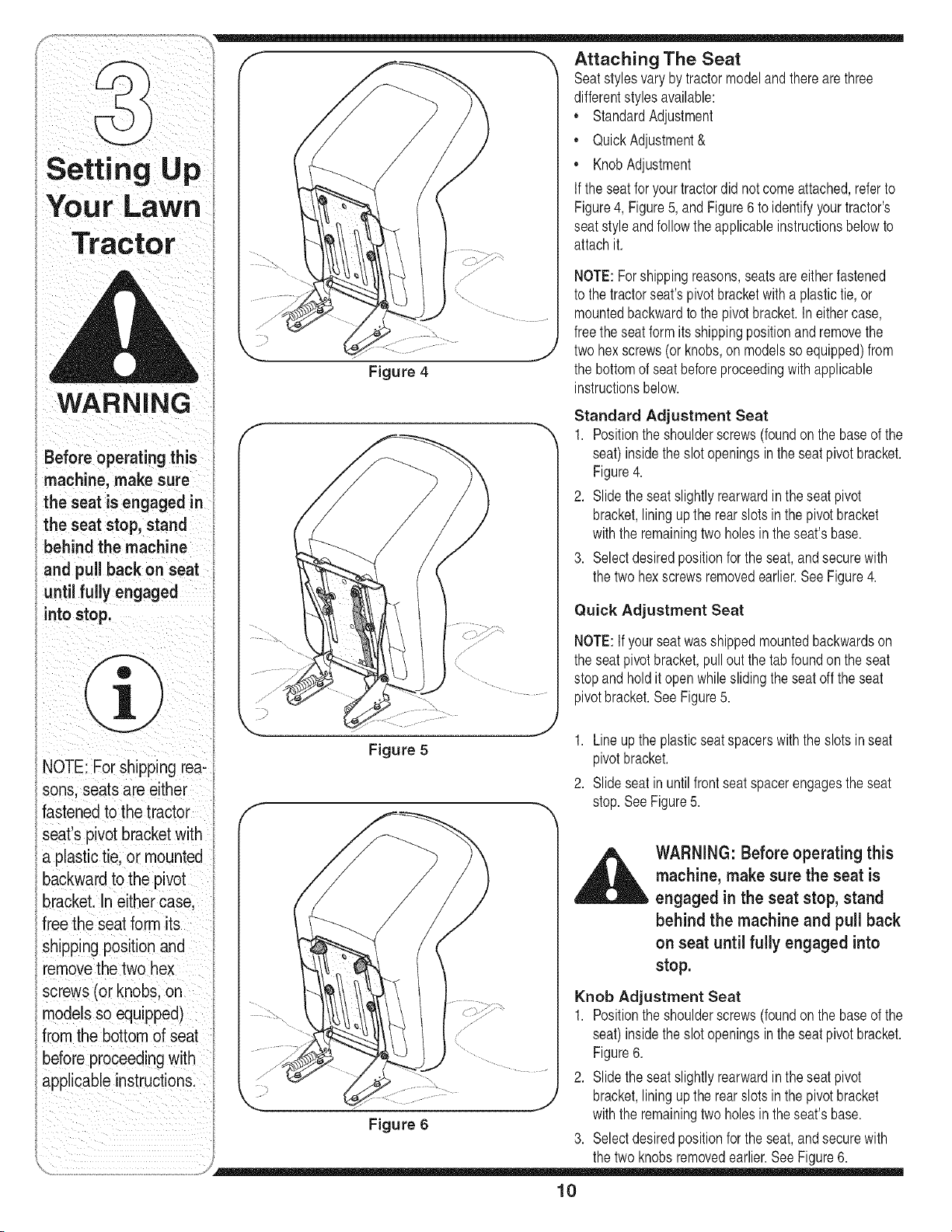
Standard Adjustment Seat
1. Positionthe shoulderscrews(foundon the baseof the
seat)insidethe slot openingsin the seat pivotbracket.
Figure4.
2. Slidetheseatslightlyrearwardin the seatpivot
bracket,liningupthe rearslots inthe pivotbracket
withthe remainingtwo holesinthe seat'sbase.
3. Selectdesiredpositionforthe seat,andsecurewith
the twohexscrewsremovedearlier.SeeFigure4.
Quick Adjustment Seat
NOTE:If yourseatwasshippedmountedbackwardson
the seatpivotbracket,pulloutthe tab foundonthe seat
stopandholdit openwhileslidingthe seatoffthe seat
pivotbracket.SeeFigure5.
Figure 5
1. Lineup the plasticseatspacerswith the slotsin seat
pivotbracket.
2. Slideseat in until frontseat spacerengagesthe seat
stop.See Figure5.
_IL ARNING: Before operating this
machine, make sure the seat is
engaged in the seat stop, stand
behind the machine and pull back
shipping position and on seat until fully engaged into
removethe two hex stop.
screws (or knobs, on Knob Adjustment Seat
models so equipped) 1. Positionthe shoulderscrews (foundon the baseof the
from the bottom of seat seat)insidethe slot openingsin the seat pivotbracket.
Figure6
before proceed!ngw!th ............... .
annlicable instructions ........... 2. Slide theseatslightlyrearwardinthe seatpivot
FF ' ..... ....
........ bracket liningupthe rearslots inthe pivotbracket
_.. _ .... ,
w th the reman ng two hoes n the seats base
Figure 6
3. Selectdesiredpositionforthe seat,andsecurewith
_ the twoknobsremovedearlier.See Figure6.
10
Identifying the Mulch Plug (if so f , "X Z
• \\
equipped) _ \ / ..... ,.... . } L_J I
, , ' X \_
On tractormodelsso equ=ppeda mulchplugcan e=ther | _ / ......',, |
/ / _, /
be foundwithinthe cuttingdeck'sdischargeopeningor _,
!
packed separately withyour unit. ........
Setting Up
Ii
NOTE:Refer to Mulchingon page19for moredetailed
information.
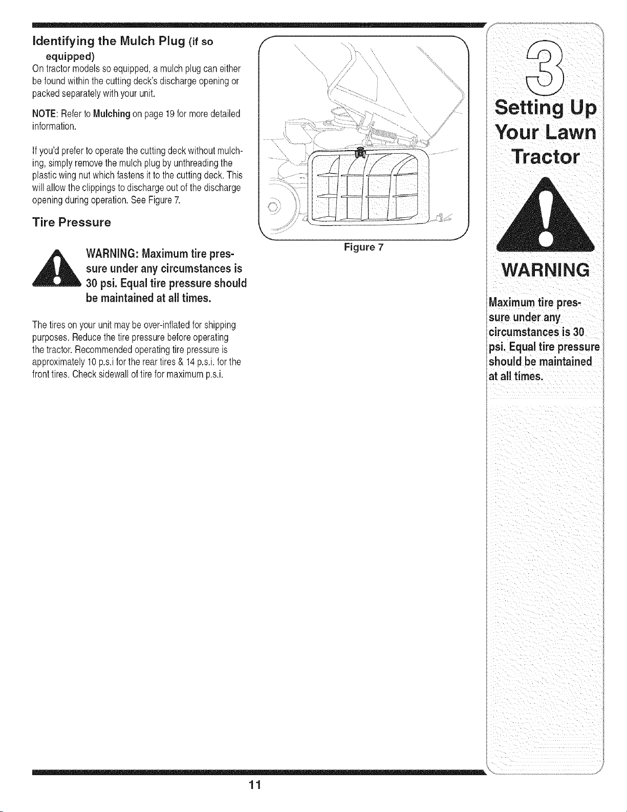
If you'dpreferto operatethe cuttingdeckwithoutmulch-
ing, simplyremovethe mulch plugby unthreadingthe
plasticwing nutwhichfastensit to the cuttingdeck.This
will allowthe clippingsto dischargeout of the discharge
openingduringoperation.SeeFigure7.
Tire Pressure
Your Lawn
Tractor
_ ARNING: Maximum tire pres-
sure under any circumstancesis
30 psi. Equal tire pressure should
be maintained at all times.
The tiresonyour unitmay be over-inflatedfor shipping
purposes.Reducethe tirepressurebeforeoperating
the tractor.Recommendedoperatingtire pressureis
approximately10p.s.ifor the rear tires & 14p.s.i,for the
fronttires.Checksidewallof tirefor maximump.s.i.
Figure 7
WARNING
Maximum tire pres-
sure under any
circumstances is 30
psi," Equal tire pressure
should be maintained
at all times.
li
\
11
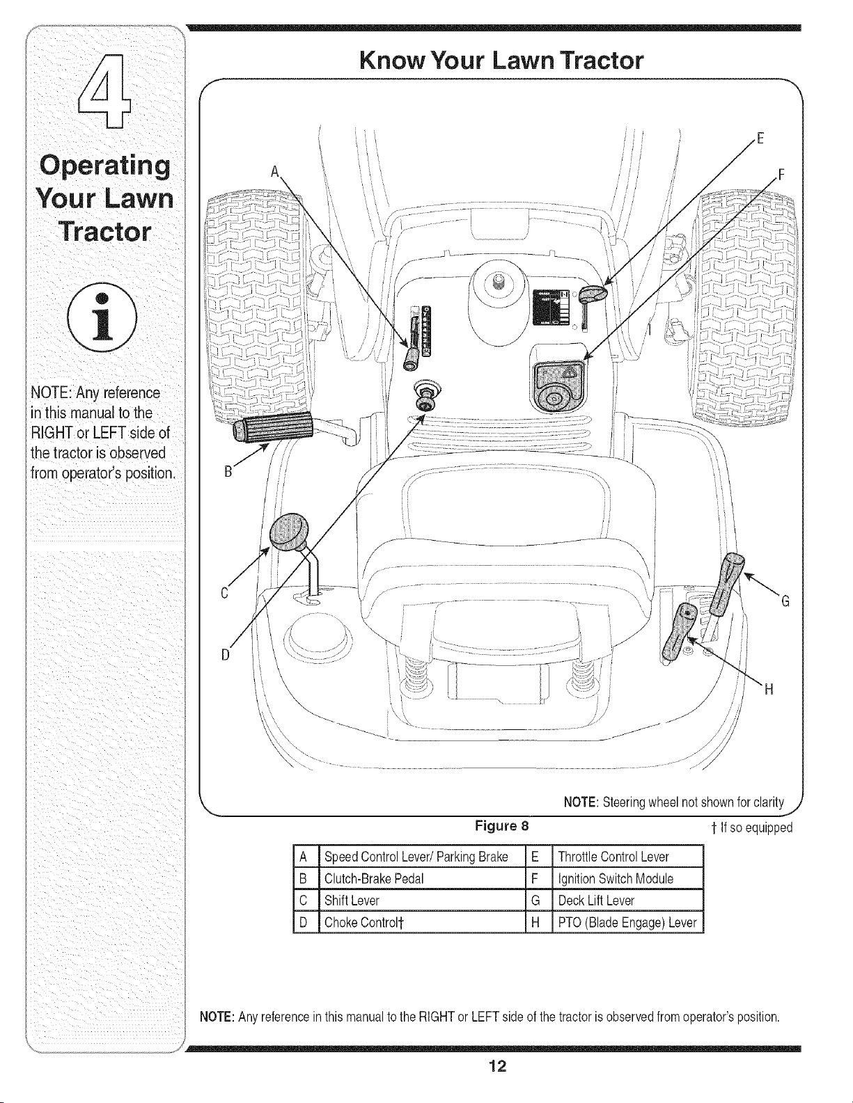
NOTE:Anyreference
inthismanualtothe
RIGHTorLEFTsideof
thetractorisobserved
fromoperator'sposition.
\ \
\\\\
\
Figure 8
NOTE:Steeringwheelnot shownforclarity,/
1 If so equipped
A SpeedControlLever/ParkingBrake E ThrottleControlLever
B Clutch-BrakePedal F IgnitionSwitchModule
C ShiftLever G DeckLift Lever
D ChokeControl1" H PTO(Blade Engage)Lever
NOTE:Anyreferencein this manualto the RIGHTor LEFTside of the tractoris observedfromoperator'sposition.
12
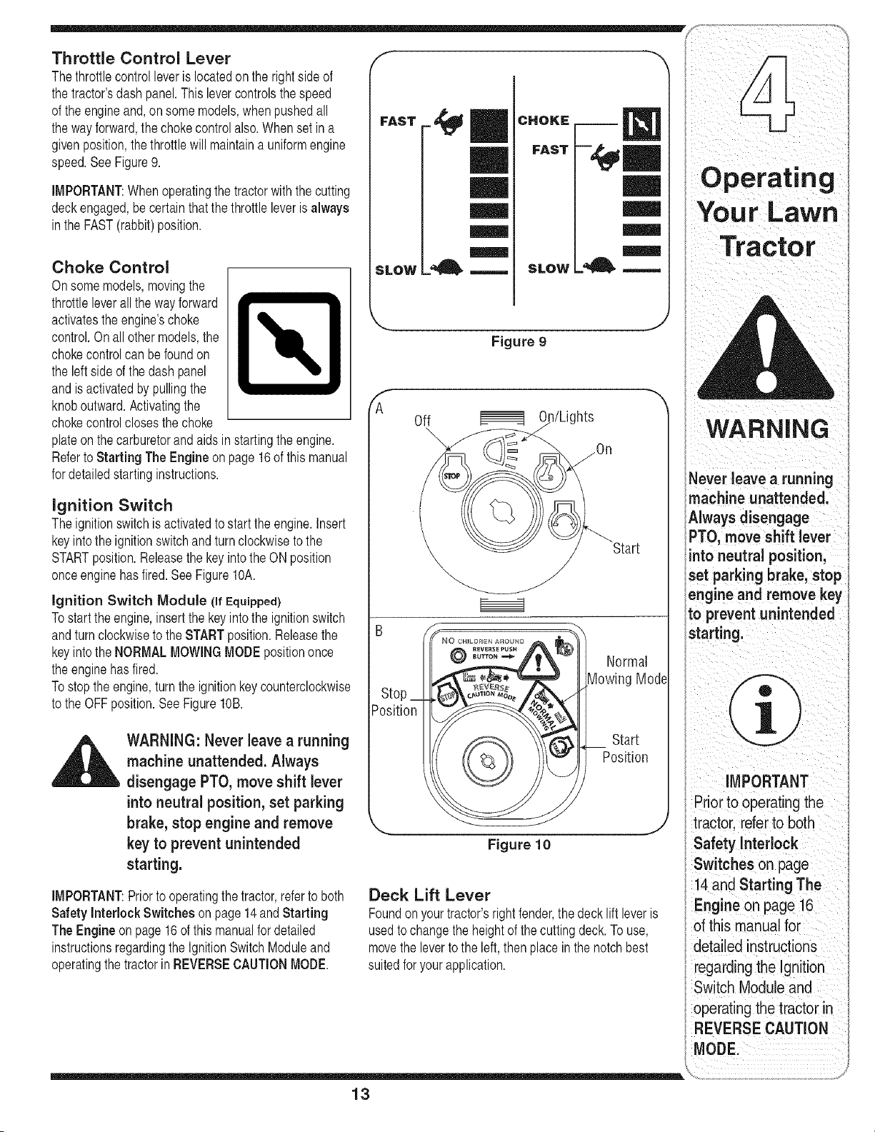
Throttle Control Lever f "_
Thethrottlecontrolleveris locatedon the rightside of
the tractorsdash panel.This levercontrolsthe speed
of the engineand,on somemodels,when pushedall
the wayforward,the chokecontrol also.Whenset in a
givenposition,the throttlewill maintaina uniformengine
speed.SeeFigure9.
IMPORTANT:Whenoperatingthetractorwith the cutting
deckengaged,be certainthat the throttleleveris always
inthe FAST(rabbit)position.
Choke Control
Onsomemodels,movingthe
throttleleverallthe wayforward
activatestheengine'schoke _.
control.On all othermodels,the
lk
chokecontrolcan befoundon
the leftside of thedash panel
andis activatedby pullingthe
knoboutward.Activatingthe
chokecontrolclosesthe choke
plateon the carburetorand aids in startingthe engine.
Referto Starting The Engine on page16of this manual
for detailedstartinginstructions.
ignition Switch
Theignitionswitchis activatedto startthe engine.Insert
keyintothe ignitionswitchandturnclockwisetothe
STARTposition.Releasethe keyintothe ON position
onceengine hasfired.SeeFigureIOA.
ignition Switch Module (if Equipped)
Tostartthe engine,insertthe keyintothe ignitionswitch
andturnclockwiseto theSTARTposition.Releasethe
keyintothe NORMALMOWINGMODEpositiononce
the enginehasfired.
Tostop the engine,turnthe ignitionkey counterclockwise
to the OFFposition.See Figure10B.
WARNING: Never leave a running
machine unattended. Always
disengage PTO, move shift lever
into neutral position,set parking
brake, stop engine and remove
key to prevent unintended
starting.
IMPORTANT:Priorto operatingthe tractor,referto both
Safety Interlock Switches on page 14andStarting
The Engine on page16of thismanualfordetailed
instructionsregardingthe IgnitionSwitchModuleand
operatingthetractorin REVERSECAUTIONMODE.
FAST _
==_==
SLOW =_ SLOW
Figure 9
J
F
A
Off On/Lights
Start
)sition
©
-,,,
Normal
Mode
Figure 10
Start
Position
WARNING
Never leave a running
machine unattended.
Awaysdsengage
PTO, move sh'ft ever
intoneutralposition;
}et parking brake, stop
;ngine and remove key
to prevent unintended
iMPORTANT
Prior to operating the
tractorl refer to both
Safety Interlock
,0ion
Starting The
Deck Lift Lever
, Engine on page 16
Foundon yourtractors rightfender,the decklift leveris .
of this manual for
usedto changethe heightof thecuttingdeck.To use,
movethe leverto the left, thenplace inthe notchbest detailed instructions
suitedfor yourapplication, regarding the Ignition
13
erating
NOTE: The parking
brake must be Setif the
operator leaVeSthe seat
with the engine rum
ning orthe enginevvil!
automatically shut off,
NOTE: The PTO(Blade
Engage) lever must
in the disengaged (PT(
OFF) positionwhen
IMPORTANT
Never force the shift
!ever,Doing SOmay
result in serious
damage to the tractor's
transmission.
_ ii i _iI i
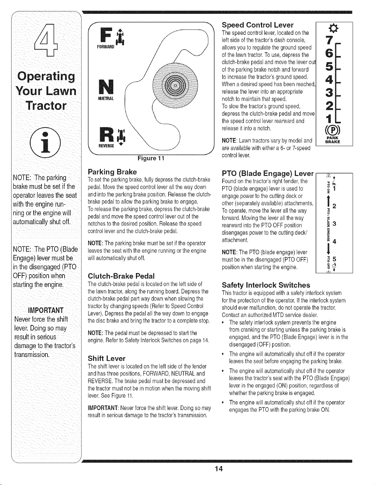
FORWARD
RUETEAL
REVERSE
Figure 11
Speed Control Lever
Thespeedcontrollever,locatedon the
leftside of the tractor'sdashconsole,
allowsyouto regulatethegroundspeed
of the lawntractor.To use,depressthe
clutch-brakepedalandmovethe leverou
of the parkingbrakenotchand forward
to increasethe tractor'sgroundspeed.
Whena desiredspeedhas beenreached
releasethe leverintoan appropriate
notchto maintainthatspeed.
Toslow the tractor'sgroundspeed,
depressthe clutch-brakepedalandmow
the speedcontrol leverrearwardand
releaseit intoa notch.
NOTE:Lawntractorsvaryby modeland
areavailablewith eithera6- or 7-speed
controllever.
Parking Brake
Toset the parkingbrake,fullydepressthe clutch-brake
pedal.Movethe speedcontrolleverall the way down
andintothe parkingbrakeposition.Releasethe clutch-
brakepedalto allowthe parkingbraketo engage.
Toreleasethe parkingbrake,depressthe clutch-brake
pedaland movethe speedcontrolleverout of the
notchesto the desiredposition.Releasethe speed
controlleverand the clutch-brakepedal.
NOTE:The parkingbrakemustbeset if theoperator
leavestheseat with the enginerunningor theengine
willautomaticallyshut off.
Clutch=Brake Pedal
Theclutch-brakepedal is locatedon the leftside of
the lawntractor,along the runningboard.Depressthe
clutch-brakepedalpart waydownwhenslowingthe
tractorby changingspeeds (Referto SpeedControl
Lever).Depressthe pedalall theway downto engage
thedisc brakeand bringthe tractorto a completestop.
NOTE:The pedal mustbedepressedto startthe
engine.Referto SafetyInterlockSwitcheson page 14.
Shift Lever
Theshift leveris locatedonthe leftsideof thefender
andhasthree positions,FORWARD,NEUTRALand
REVERSE.The brakepedal mustbe depressedand
thetractor mustnotbe in motionwhenthe movingshift
lever.SeeFigure11.
IMPORTANT:Neverforcetheshift lever.Doingso may
resultinseriousdamageto the tractor'stransmission.
PTO (Blade Engage) Lever
Foundon thetractor'sright fender,the
PTO(bladeengage)leveris usedto
engagepowerto the cuttingdeckor
other(separatelyavailable)attachments.
Tooperate,movethe leverall the way
forward.Movingthe leverallthe way
rearwardintothe PTOOFF position
disengagespowerto the cuttingdeck/
attachment.
NOTE:The PTO(bladeengage)lever
mustbe inthe disengaged(PTOOFF)
positionwhenstartingthe engine.
'tl f
o
p
_3
r_
i'
_5
0
Safety Interlock Switches
Thistractoris equippedwith a safetyinterlocksystem
for theprotectionof the operator.If the interlocksystem
shouldevermalfunction,donot operatethe tractor.
ContactanauthorizedMTDservicedealer.
• Thesafetyinterlocksystempreventstheengine
fromcrankingor startingunlessthe parkingbrakeis
engaged,and the PTO(BladeEngage)leveris in the
disengaged(OFF)position.
• Theenginewill automaticallyshutoff if theoperator
leavestheseat beforeengagingthe parkingbrake.
• Theenginewill automaticallyshutoff if theoperator
leavesthetractor'sseat with the PTO(BladeEngage)
leverin the engaged(ON) position,regardlessof
whetherthe parkingbrakeis engaged.
• Theenginewill automaticallyshutoff if theoperator
engagesthe PTOwiththe parkingbrakeON.
14
(BladeEngage)leveris movedintothe engaged(ON)
positionwiththe shift leverin Reverse.
Models with Reverse Caution Mode
, With the ignitionkeyin the NORMALMOWING
position,the enginewill automaticallyshut off if the
PTO(Blade Engage)leveris movedintothe engaged
(ON) positionwiththe shift leverin Reverse.
WARNING: Do not operate the
tractor if the interlock system
is malfunctioning. This system
was designed for your safety and
protection.
Reverse Caution Mode (if Equipped)
WARNING: Use extreme caution
while operating the tractor in
the REVERSE CAUTION MODE.
Always look down and behind
before and while backing. Do not
operate the tractor when children
or others are around. Stop the
tractor immediately if someone
enters the area.
TheREVERSECAUTIONMODEpositionof the key
switchmoduleallowsthetractorto be operatedin
reversewiththe blades(PTO)engaged.
IMPORTANT:Mowingin reverseis notrecommended.
Touse the REVERSECAUTIONMODE:
IMPORTANT:TheoperatorMUSTbe seated in the
tractorseat.
1. Start the engineas instructedon page 16under
Starting The Engine.
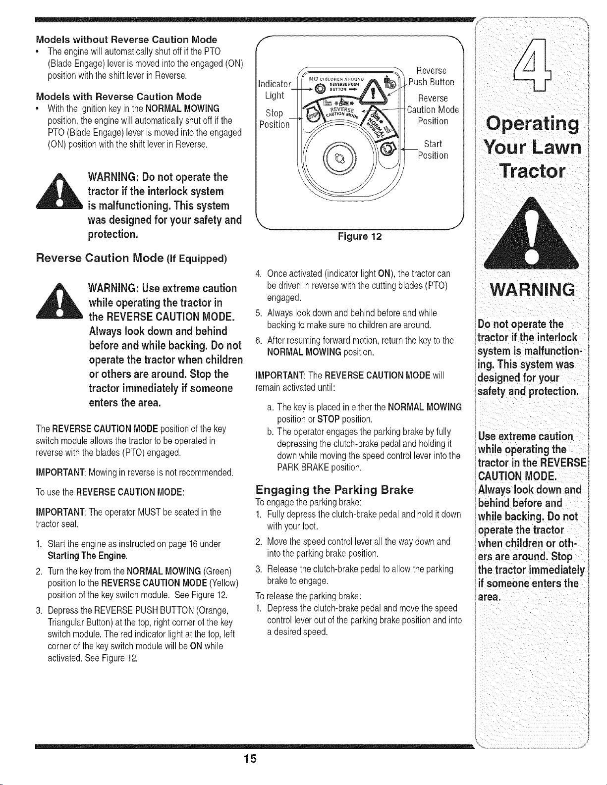
2. Turnthe keyfromthe NORMALMOWING(Green)
positionto the REVERSECAUTIONMODE(Yellow)
positionof the keyswitchmodule. See Figure12.
3. Depressthe REVERSEPUSHBUTTON(Orange,
TriangularButton)at the top,rightcornerof the key
switchmodule.The red indicatorlightat thetop, left
cornerof the keyswitch modulewill beON while
activated.See Figure12.
Reverse
Indicator Push Button
Light Reverse
Stop CautionMode
Position Position
©
Start
Position
Your Lawn
Figure 12
4. Onceactivated(indicatorlightON), the tractorcan
be driveninreversewiththecutting blades(PTO)
engaged.
5. Alwayslookdownandbehindbeforeand while
backingto makesure nochildrenare around.
6. After resumingforwardmotion,returnthe key to the
NORMALMOWINGposition.
IMPORTANT:The REVERSECAUTIONMODEwill
remainactivateduntil:
a. The keyis placedin eitherthe NORMALMOWING
positionor STOPposition.
b. The operatorengagesthe parkingbrakeby fully
depressingthe clutch-brakepedalandholdingit
downwhile movingthe speedcontrolleverintothe
PARKBRAKEposition.
Engaging the Parking Brake
Toengagethe parkingbrake:
1. Fullydepressthe clutch-brakepedaland hold it down
withyourfoot.
2. Move thespeedcontrolleverall the waydownand
into the parkingbrakeposition.
3. Releasetheclutch-brakepedalto allowthe parking
braketo engage.
To releasethe parkingbrake:
1. Depressthe clutch-brakepedaland movethe speed
controlleverout of the parkingbrakepositionand into
a desiredspeed.
WARNING
i Do not operate the
l
Itractor if the interlock
isystem is malfunction-
I rig. Th s system was
idesigned for your
safety and protection.
Use extreme caution
while operating the
tractor in the REVERSE
CAUTION MODE.
Always look down and
behind before and
while backing. Do not
operate the tractor
Whenchildren or oth-
ers are around. Stop
the tractor immediately
if someone enters the
area.
15
I:ing
otor
WARNING
Keep hands and feet
away from the dis-
charge opening of the
cutting deck.
Do not operate the
tractor if the interlock
system is malfunction-
ing. This system was
designed for your
safety and protection.
If you strike a foreign
object, stop the
engine, disconnect
the spark plug wire(s)
and ground against
the engine. Thoroughly
inspectthe machine
for any damage. Repair
the damage before
restarting and operat-
ing.
Setting the Cutting Height
1. Selectthe heightpositionof the cuttingdeckby
placingthe deck lift leverin any of the six different
cuttingheightnotcheson the rightside of the fender.
2. Adjustthe deckwheels,if equipped,so thattheyare
between1A-inchand Y2-inchabovethe groundwhen
the tractoris on a smooth,flatsurfacesuch as a
driveway.
_ ARNING: Keep hands and feet
away from the discharge open-
ing of the cutting deck.
NOTE:On modelsso equipped,the deckwheelsarean
anti-scalpfeatureof thedeckandare notdesignedto
supportthe weightof the cuttingdeck.
Referto Levelingthe Deckon page20of this manual
for moredetailedinstructionsregardingvariousdeck
adjustments.
Starting the Engine
WARNING: Do not operate the
tractor if the interlock system is
malfunctioning. This system was
designed for your safety and
protection.
AVOID SERIOUS INJURY OR DEATH
GO UPAND DOWNSLOPES,NOT ACROSS.
AVOIDSUDDENTURNS.
DO NOT OPERATETHEUNITWHERE IT COULDSLIP ORTIE
IFMACHINE STOPSGOING UPHILL,STOP BLADE(S)AND
BACK DOWNHILLSLOWLY.
DO NOT MOWWHEN CHILDRENOR OTHERS ARE AROUND.
NEVER CARRYCHILDREN,EVENWITH BLADES OFE
LOOK DOWNAND BEHINDBEFOREAND WHILE BACKING.
KEEP SAFETYDEVICES(GUARDS,SHIELDS,AND SWlTCHE_
IN PLACEAND WORKING.
REMOVEOBJECTSTHATCOULDBE THROWNBYTHE
BLADE(S).
KNOW LOCATIONAND FUNCTIONOF ALL CONTROLS.
BE SUREBLADE(S) AND ENGINEARESTOPPEDBEFORE
PLACINGHANDSORFEET NEAR BLADE(S).
BEFORE LEAVINGOPERATOR'SPOSITION,DISENGAGE
BLADE(S), PLACETHE SHIFT LEVERIN NEUTRAL,ENGAGE
BRAKE LOCK,SHUT ENGINEOFF AND REMOVEKEY.
READ OPERATOR'S MANUAL
Stopping the Engine
NOTE:Referto the TRACTORSET-UPon page8 of
thismanualfor GasolineandOil fill-upinstructions.
1. Insertthe tractorkeyinto the ignitionswitch.
2. Placethe PTO(BladeEngage)leverinthe disen-
gaged(OFF)position.
3. Engagethetractor'sparkingbrake.
4. Activatethe chokecontrol.
5. Turnthe ignitionkeyclockwiseto the STARTposi-
tion.Afterthe enginestarts, releasethe key.Itwill
returnto theON position.
iMPORTANT:Do NOTholdthe keyin the START
positionfor longerthanten secondsat a time. Doingso
maycausedamageto yourengine'selectricstarter.
6. After theenginestarts, deactivatethechoke control
andplacethe throttlecontrolin theFASTposition.
_ ARNING: if you strike a foreign
object, stop the engine, discon-
nect the spark plug wire(s) and
ground against the engine. Thor-
oughly inspect the machine for
any damage. Repair the damage
before restarting and operating
1. If the bladesare engaged,placethe PTO(Blade
Engage)leverin the disengaged(OFF) position.
2. Turnthe ignitionkey counterclockwiseto the STOP
position.
3. Removethe keyfromthe ignitionswitchto prevent
unintendedstarting.
NOTE:Do NOTleavethe chokecontrolonwhile operat-
ingthe tractor.Doingso will result in a "rich" fuelmixture
andcausethe engineto run poorly.
16
Driving The Tractor
_ ARNING: Avoid sudden starts,
ex-cessive speed and sudden
stops.
WARNING: Do not leave the seat
of the tractor without first plac-
ing the PTO (Blade Engage) lever
in the disengaged (OFF) posi-
tion, depressing the brake pedal
and engaging the parking brake.
If leaving the tractor unattended,
also turn the ignition key off and
remove the key.
Always look down and behind
before and while backing up to
avoid a back-over accident.
1. Depressthe brakepedalto releasethe parkingbrake
andlet the pedalup.
2. Movethe throttleleverintothe FAST(rabbit)position.
3. Placetheshift leverin eitherthe FORWARDor
REVERSEposition.
IMPORTANT:Do NOTusethe shift leverto changethe
directionof travelwhenthe tractoris in motion.Always
usethe brakepedalto bringthe tractorto a complete
stopbeforeshifting.
4. Releasethe parkingbrakebydepressingthe clutch-
brakepedaland positioningthe speedcontrolleverin
desiredposition.
IMPORTANT:First-timeoperatorsshouldusespeed
positions1 or 2. Becomecompletelyfamiliarwith the
tractor'soperationandcontrolsbeforeoperatingthe
tractorin higherspeed positions.
5. Releaseclutch-brakepedalslowlyto put unitinto
motion.
6. The lawntractor isbroughtto a stopbydepressing
the clutch-brakepedal.
NOTE:Whenoperatingthe unit initially,therewill be little
differencebetweenthe highesttwospeedsuntilafter the
beltshaveseatedthemselvesinto the pulleysduring the
break-inperiod.
_ ARNING: Before leaving the
operator's position for any
reason, disengage the blades,
place the shift lever in neutral,
engage the parking brake, shut
engine off and remove the key.
IMPORTANT:Whenstoppingthe tractorforany reason
whileon a grasssurface,always:
1. Placethe shift leverin neutral,
2. Engagethe parkingbrake,
3. Shutengineoff andremovethe key.
Doingso will minimizethe possibilityof havingyourlawn
"browned"by hot exhaustfromyourtractor'srunning
engine.
If unit stalls with speedcontrolin high speed,or if unit
will notoperatewithspeedcontrolleverin a lowspeed
position,proceedas follows:
1. Placeshift leverin NEUTRAL.
2. Restartengine.
3. Placespeedcontrol leverinhighestspeedposition.
4. Releaseclutch-brakepedalfully.
5. Depressclutch-brakepedal.
6. Placespeedcontrol leverindesiredposition.
7. Placeshift leverin eitherFORWARDor REVERSE,
andfollownormaloperatingprocedures.
17
I _ I _ i i i _'
Operatinq
Your Lawn
l /
WARNING
iAvoJdsudden starts,
i ex-cesslve speed and
I sudden stops.
Do not leave the seat
of the tractor without
first placingthe PTO
(Blade Engage) lever in
the disengaged (OFF)
position, depressing
the brake pedal and
engaging the parking
brake, if leaving the
tractor unattended,
also turn the ignition
key off and remove the
key.
Always look down
and behind before
and while backi ng up
to avoid a back-over
accident.
WARNING
Do not mow on inclines
with a slope in excess
of 15 degrees (a rise
of approximately 2-1/2
feet every 10 feet). The
tractor could overturn
and cause serious
injury.
1"ohelp avoid blade
:ontact or a thrown
object injury, keep
bystanders, helpers,
:hildren and pets at
east75 feet from the
_achine while it is in
)peration. Stop ma-
:hine if anyone enters
:hearea.
Driving On Slopes
Referto the SLOPEGAUGEon page3 to helpdeter-
mineslopeswhereyou mayoperatethe tractorsafely.
_. WARNING: Do not mow on
inclines with a slope in excess
__ of 15 degrees (a rise of approxi-
mately 2-1/2 feet every 10 feet).
The tractor could overturn and
cause serious injury.
Mowupanddownslopes,NEVERacross.
Exerciseextremecautionwhenchangingdirection
onslopes.
• Watchfor holes, ruts,bumps,rocks, or otherhidden
objects.Uneventerraincouldoverturnthe machine.
Tall grasscan hideobstacles.
• Avoidturnswhendrivingona slope. If a turn must
be made,turn downthe slope.Turningup a slope
greatlyincreasesthechanceof a roll over.
,, Avoidstoppingwhendrivingupa slope. If it is
necessaryto stopwhiledrivingupa slope, start up
smoothlyandcarefullyto reducethe possibilityof
flippingthetractoroverbackward.
Engaging the Blades
Engagingthe PTO(Blade Engage)transferspowerto
thecutting deckor other(separatelyavailable)attach-
ments.To engagethe blades,proceedas follows:
1. Movethe throttlecontrolleverto the FAST(rabbit)
position.
2. Graspthe PTO(BladeEngage)leverand pivotit all
the wayforwardinto theengaged(ON) position.
3. Keepthe throttleleverin the FAST(rabbit)position
for the mostefficientuseof the cuttingdeck or other
(separatelyavailable)attachments
IMPORTANT:ModelswithReverseCaution Mode:
Theenginewill automaticallyshut off if the PTOis
engagedwiththe shift leverin positionfor reversetravel
withthe ignitionkey in the NORMALMOWINGposition.
Models without ReverseCaution Mode:
The PTO(BladeEngage)levermustbe in the disen-
gaged(OFF)positionwhenstartingthe engine,when
travelingin reverse,andif the operatorleavesthe seat.
Referto SafetyInterlockSwitcheson page14.
Using the Deck Lift Lever
Toraisethe cuttingdeck, movethe decklift leverto the
left, thenplace it in the notch bestsuited for yourapplica-
tion.Referto SettingThe CuttingHeightearlierin this
section.
Mowing
_ ARNING: To help avoid blade
contact or a thrown object injury,
__ keep bystanders, helpers, children
and pets at least 75 feet from the
machine while it is in operation.
Stop machine if anyone enters the
area.
Thefollowinginformationwill be helpfulwhenusingthe
cuttingdeckwith yourtractor:
l_. ARNING: Plan your mowing
patternto avoid discharge of
-- materials toward roads, sidewalks,
bystanders and the like. Also,
avoid discharging material against
a wall or obstruction which may
cause discharged material to
ricochet back toward the operator.
,, Do not mowat high groundspeed,especiallyif a
mulchkit or grasscollectoris installed.
,, Forbestresultsit is recommendedthat the firsttwo
lapsbe cutwiththe dischargethrowntowardsthe
center.After thefirst twolaps,reversethe directionto
throwthe dischargeto the outsidefor the balanceof
cutting.Thiswill givea betterappearanceto the lawn.
,, Do notcut thegrasstoo short.Shortgrassinvites
weedgrowthand yellowsquicklyin dryweather.
,, Mowingshouldalwaysbe done with theengineat full
throttle.
,, Underheavierconditionsit maybenecessarytogo
backover thecut areaa secondtime to get a clean
cut.
18
,, Do NOTattemptto mow heavybrushandweedsand
extremelytall grass.Yourtractoris designedto mow
lawns,NOTclearbrush.
,, Keepthe bladessharpand replacethe bladeswhen
worn.RefertoCutting Blades on page25 of this
manualfor properblade sharpeninginstructions.
Mulching (If Equipped)
Selectmodelscomeequippedwitha mulch kit which
incorporatesspecialblades,alreadystandardon the
tractor,ina processof recirculatinggrassclippings
repeatedlybeneaththecutting deck.The ultra-fine
clippingsarethenforced backinto thelawnwherethey
actas a naturalfertilizer.
Observethe followingpointsfor the bestresultswhen
mulching:
,, Neverattemptto mulchif the lawnis damp.Wetgrass
tendsto stickto the undersideof the cuttingdeck
preventingpropermulchingof the clippings.
,, Do NOTattemptto mulch morethan 1/3the total
heightof thegrassor approximately1-1/2inches.
Doingso will causethe clippingsto clump up beneath
the deckandnotbe mulchedeffectively.
,, Maintaina slowgroundspeedto allowthe grass
clippingsmoretime to effectivelybe mulched.
,, Alwayspositionthe throttlecontrol leverinthe FAST
(rabbit)positionand allowit to remaintherewhile
mowing.Failingto keepthe engineat full throttle
placesstrainonthe tractor'sengineanddoes not
allowthe bladesto properlymulchgrass.
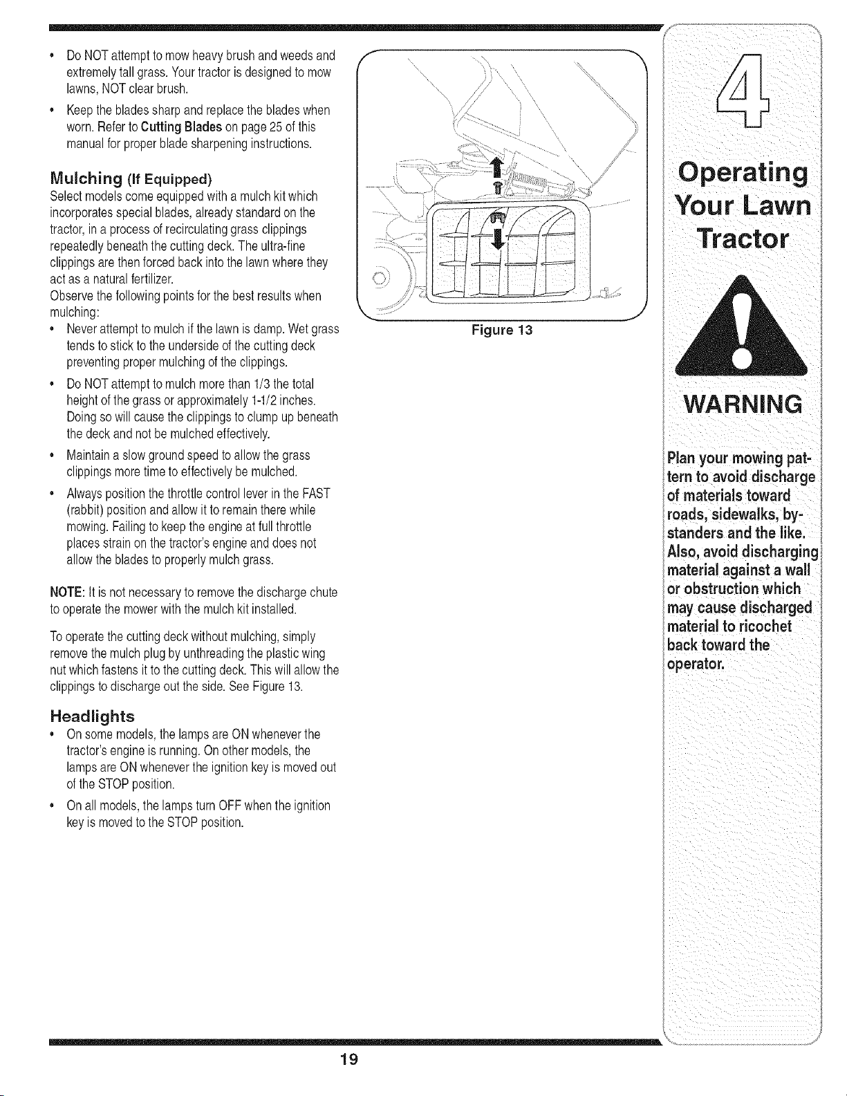
NOTE:It is not necessaryto removethe dischargechute
to operatethe mowerwith the mulchkit installed.
Tooperatethe cuttingdeck withoutmulching,simply
removethe mulchplug by unthreadingthe plasticwing
nut whichfastensit to thecuttingdeck.This will allowthe
clippingsto dischargeout the side.SeeFigure13.
Headlights
,, On some models,the lampsareON wheneverthe
tractor'sengineis running.Onother models,the
lampsareON wheneverthe ignitionkeyis movedout
of the STOPposition.
,, On all models,the lampsturn OFFwhenthe ignition
keyis movedto the STOPposition.
Figure 13
19
i Plan your mowing pat-
_tern to avoid discharge
i of materials toward
i roads, sidewalks, by-
I standers and the like.
'Also, avoid discharging
material against a wall
or obstructionwhich
may cause discharged
material to ricochet
back toward the
operator.
l R E
Adjust=ha
Your Lawn
Tractor
i
, WARNING
I
i Never attempt to
i ....
i make any aajusi-
merits while the
engine is running,
i
i except where spec=-
f ed n the operator s
i manual.
i Never attempt to
!adjust the brakes
_while the engine
i is running. Always
idisengage PTO, move
ishift lever into neutral
i position, stop engine
land remove key to
i preventunintended
starting.
Figure 14
Figure 15
_ ARNING: Never attempt to
make any adjustments while
-- the engine is running, except
where specified in the operator's
manual.
Leveling the Deck
NOTE:Checkthe tractor'stire pressurebeforeperform-
ingany decklevelingadjustments.Referto Tires on
page24 for informationregardingtire pressure.
Front To Rear
The frontof the cuttingdeck is supportedbya stabilizer
barthatcan adjustedto levelthe deck from front to rear.
The frontof the deckshouldbe between1/4-inchand
3/8-inchlowerthanthe rearof thedeck. Adjustif
necessaryas follows:
1. With thetractorparkedona firm,levelsurface,place
the deckliftleverin the top notch(highestposition)
androtatethe bladenearestthe dischargechuteso
thatit is parallelwiththe tractor.
2. Measurethe distancefrom the front of thebladetip to
the groundandthe rearof the bladetip to the ground.
Thefirst measurementtaken shouldbebetween
1/4" and3/8" less thanthe secondmeasurement.
Determinethe approximatedistancenecessaryfor
properadjustmentandproceed,if necessary,to the
nextstep.
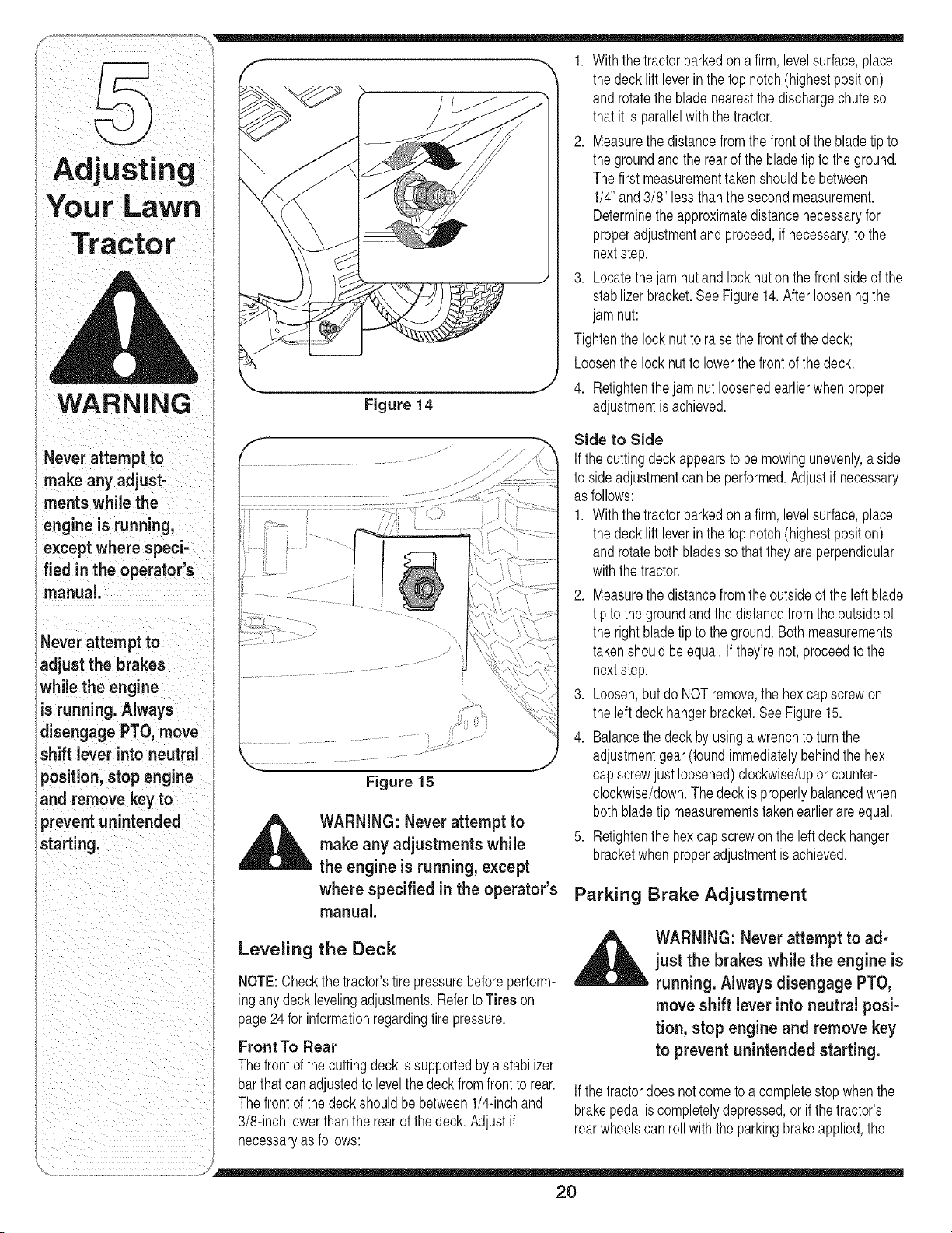
3. Locatethejam nutand lock nut on the frontsideof the
stabilizerbracket.See Figure14.After looseningthe
jam nut:
Tightenthe locknutto raisethe frontof the deck;
Loosenthe lock nut to lowerthe frontof the deck.
4. Retightenthe jam nut loosenedearlierwhenproper
adjustmentis achieved.
Side to Side
If thecutting deckappearsto be mowingunevenly,a side
to sideadjustmentcan be performed.Adjustif necessary
as follows:
1. With thetractorparkedona firm,levelsurface,place
the deckliftleverin the top notch(highestposition)
androtateboth bladesso that they are perpendicular
withthe tractor.
2. Measurethe distancefrom the outsideof the left blade
tip to the groundandthe distancefrom theoutsideof
the rightblade tipto the ground.Bothmeasurements
takenshouldbe equal.If they'renot, proceedto the
nextstep.
3. Loosen,butdo NOTremove,the hexcap screwon
the leftdeckhangerbracket.SeeFigure15.
4. Balancethe deck by usinga wrenchto turnthe
adjustmentgear(foundimmediatelybehindthe hex
capscrewjust loosened)clockwise/upor counter-
clockwise/down.Thedeck is properlybalancedwhen
both bladetip measurementstakenearlierareequal.
5. Retightenthe hex capscrewon the leftdeckhanger
bracketwhenproperadjustmentis achieved.
Parking Brake Adjustment
,_ WARNING: Never attempt to ad-
just the brakes while the engine is
running. Always disengage PTO,
move shift lever into neutral posi-
tion, stop engine and remove key
to prevent unintended starting.
If thetractordoes notcometo a completestop whenthe
brakepedal iscompletelydepressed,orif thetractor's
rearwheelscanroll withthe parkingbrakeapplied,the
20
S,,y,-
brakeis in need of adjustment.Thebrakedisc can be
foundon the rightsideof the transmissionin the rearof
the tractor.Adjustif necessaryas follows:
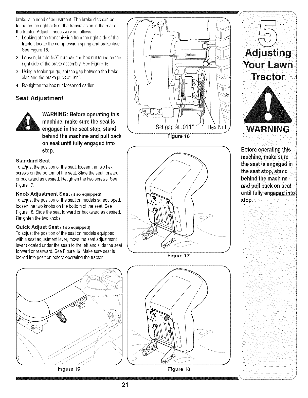
1. Lookingat thetransmissionfromthe rightside of the
tractor,locatethe compressionspringand brakedisc•
SeeFigure16.
2. Loosen,but do NOTremove,the hex nutfoundon the
rightsideof the brakeassembly•See Figure16.
3. Usinga feelergauge,setthe gapbetweenthe brake
discandthe brakepuck at .011".
4. Re-tightenthe hexnut loosenedearlier•
Seat Adjustment
_1= ARNING: Before operating this
machine, make sure the seat is
engaged in the seat stop, stand
behind the machine and pull back
on seat until fully engaged into
stop.
Standard Seat
Toadjust the positionof the seat,loosenthe two hex
screwson the bottomof the seat.Slide the seatforward
or backwardas desired.Retightenthe twoscrews.See
Figure17.
Knob Adjustment Seat (if so equipped)
Toadjust the positionof the seaton modelsso equipped,
loosenthe two knobs on the bottomof the seat. See
Figure18. Slidethe seat forwardor backwardas desired.
Retightenthe two knobs.
Quick Adjust Seat (if so equipped)
Toadjust the positionof the seaton modelsequipped
witha seat adjustmentlever,movetheseatadjustment
lever(locatedunder theseat)to the leftand slidethe seat
forwardor rearward.See Figure19.Makesureseatis
lockedintopositionbeforeoperatingthe tractor•
Set gap .011"
Figure 16
Hex Nut
f
Figure 17
,,J
WARNING
Before operating this
machine, make sure
the seat is engaged in
the seat stop, stand
behind the machine
and pull back on seat
until fully engaged into
stop.
Figure 19 Figure 18
21
WARNING
Beforeperforming
any maintenance or
repairs; disengage
PTO, move shift lever
into neutral position,
set parking brake, stop
engineand remove key
to prevent unintended
Before!ubroaring
repairing, or inspect,
ing, always disengage
PTO,move shift lever
into neutral position,
set parking brake, stop
engine and remove key
to preventunintended
NOTEIDependingon
theenginemodelfound
on your tractor,itmay
benecessaryto remove
the tractor'sside panel
in order to replace the
oi! fi!te! (if so equipped);
y
Figure 20
_i= ARNING: Before performing
any maintenance or repairs,
disengage PTO, move shift lever
into neutral position, set parking
brake, stop engine and remove
key to prevent unintended
starting.
Engine
Referto the Engine Operator/Owner Manualfor
engine maintenance instructions.
Checkengineoil level beforeeachuseas instructed
in the EngineOperator/OwnerManualpackedwithyour
unit.Follow the instructionscarefully.
Changing Engine Oil
NOTE:Dependingon the engine modelfoundon your
tractor,it maybenecessaryto removethe tractor'sside
panelinorderto replacethe oil filter (if so equipped).
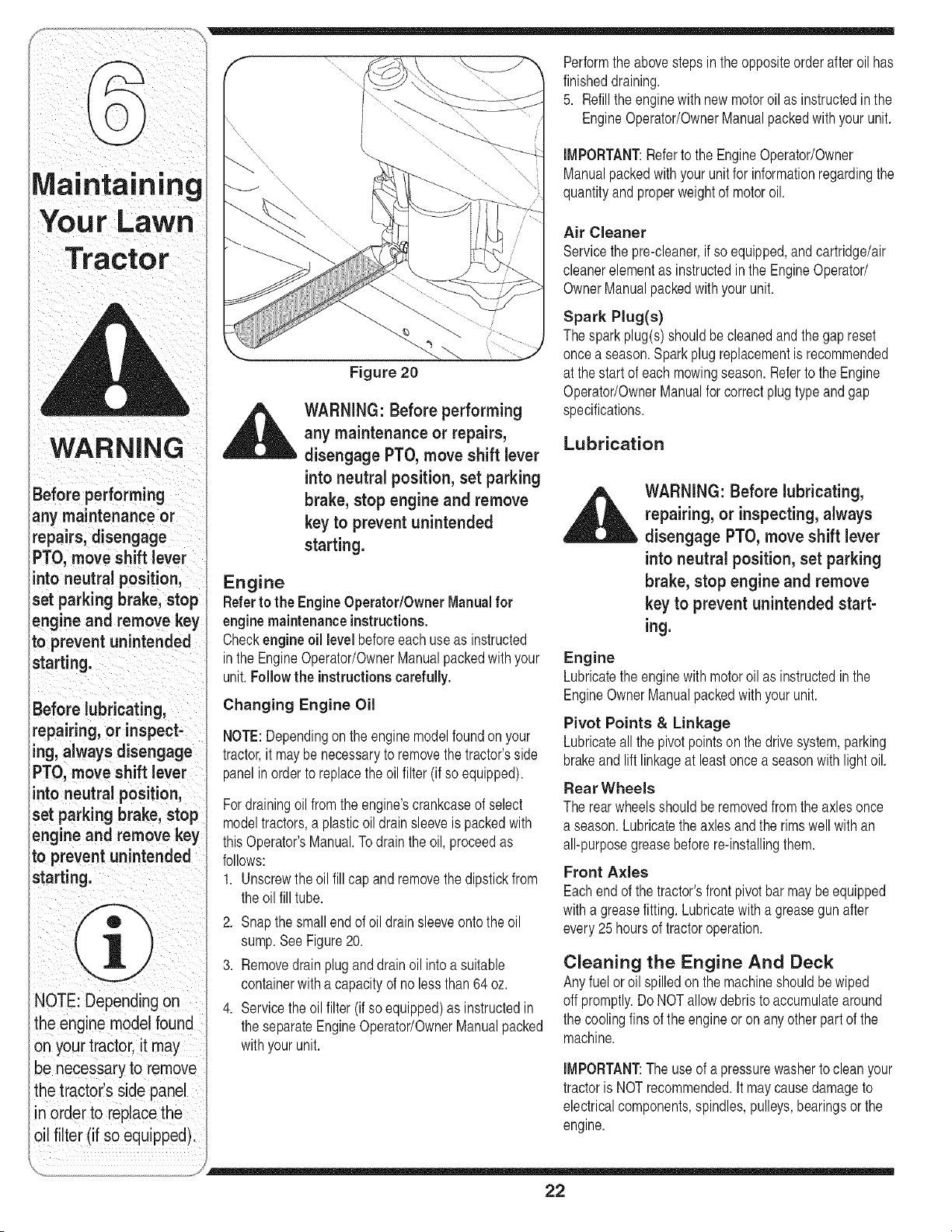
Fordrainingoil from the engine'scrankcaseof select
modeltractors,a plasticoildrainsleeveis packedwith
thisOperator'sManual.Todrain the oil, proceedas
follows:
1. Unscrewthe oilfill capand removethe dipstickfrom
the oilfill tube.
2. Snapthe smallendof oildrainsleeveontothe oil
sump.See Figure20.
3. Removedrainpluganddrainoil intoa suitable
containerwitha capacityof no lessthan 64oz.
4. Servicethe oilfilter (if soequipped)as instructedin
the separateEngineOperator/OwnerManualpacked
withyourunit.
Performthe abovestepsin theoppositeorderafteroil has
finisheddraining.
5. Refillthe enginewith newmotoroilas instructedinthe
EngineOperator/OwnerManualpackedwith your unit.
iMPORTANT:Referto the EngineOperator/Owner
Manualpackedwith yourunit for informationregardingthe
quantityand properweightof motoroil.
Air Cleaner
Servicethe pre-cleaner,if so equipped,andcartridge/air
cleanerelementas instructedin the EngineOperator/
OwnerManualpackedwithyour unit.
Spark Plug(s)
Thespark plug(s)shouldbecleanedandthegapreset
oncea season.Sparkplugreplacementisrecommended
at the startof each mowingseason.Referto the Engine
Operator/OwnerManualfor correctplugtypeandgap
specifications.
Lubrication
WARNING: Before lubricating,
repairing, or inspecting, always
disengage PTO, move shift lever
into neutral position, set parking
brake, stop engine and remove
key to prevent unintended start-
ing.
Engine
Lubricatethe enginewithmotoroil as instructedin the
EngineOwnerManualpackedwithyour unit.
Pivot Points & Linkage
Lubricateall the pivotpointson the drivesystem,parking
brakeand lift linkageat least oncea seasonwith lightoil.
Rear Wheels
The rearwheelsshouldbe removedfrom the axles once
a season.Lubricatethe axlesandthe rimswell withan
all-purposegreasebeforere-installingthem.
Front Axles
Eachend of the tractor'sfront pivot bar may be equipped
witha greasefitting.Lubricatewitha greasegun after
every25 hoursof tractoroperation.
Cleaning the Engine And Deck
Anyfuel or oil spilledon the machineshouldbewiped
off promptly.DoNOTallowdebristo accumulatearound
the coolingfins of the engine or on anyotherpart of the
machine.
iMPORTANT:The useof a pressurewasherto cleanyour
tractoris NOT recommended.It maycausedamageto
electricalcomponents,spindles,pulleys,bearingsor the
engine.
22
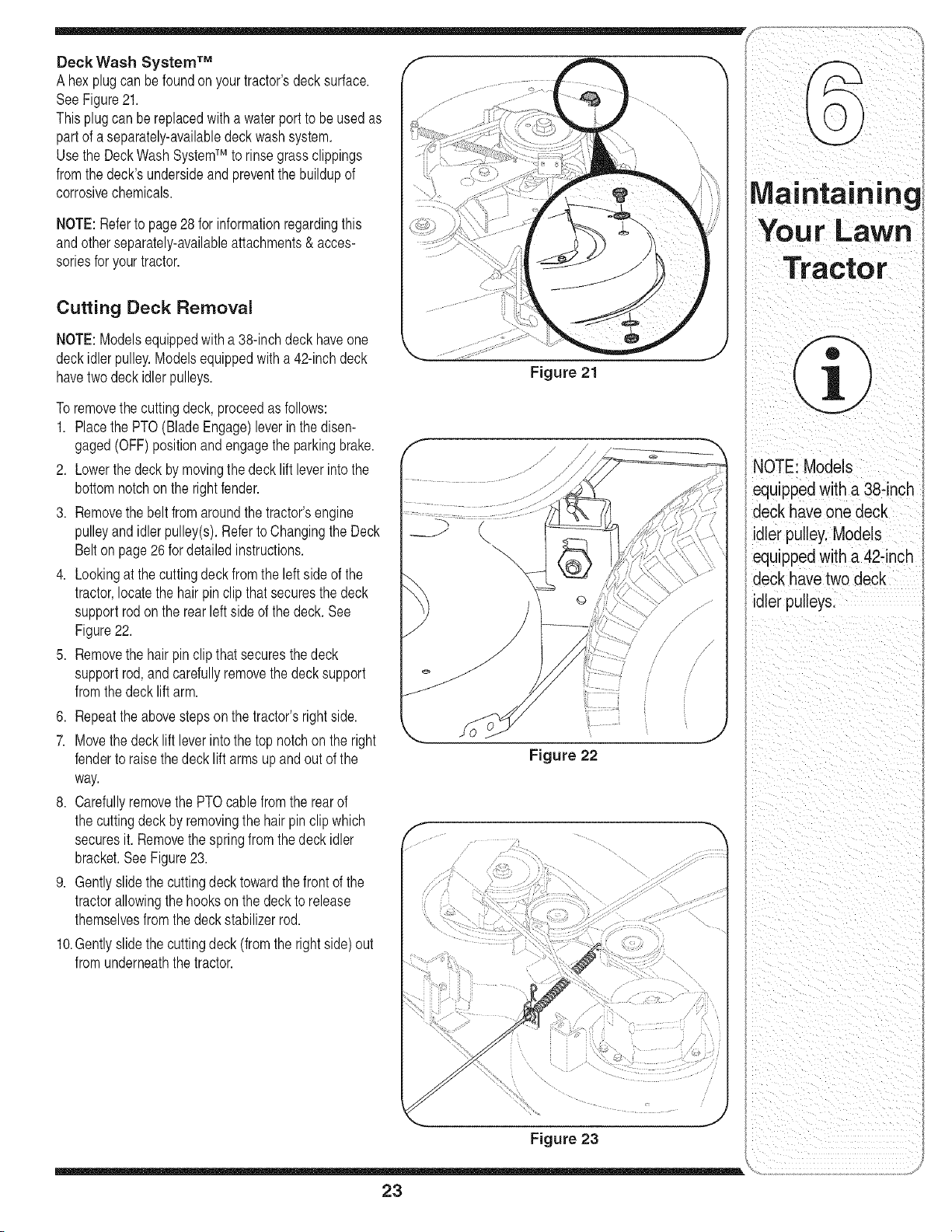
Deck Wash System TM
A hexplugcan befoundon yourtractor'sdecksurface.
SeeFigure21.
Thisplugcan bereplacedwith a waterport to beused as
partof a separately-availabledeck washsystem.
Usethe DeckWash SystemTM to rinsegrassclippings
fromthedeck'sundersideand preventthe buildupof
corrosivechemicals.
NOTE:Referto page 28 for informationregardingthis
andotherseparately-availableattachments& acces-
soriesfor yourtractor.
Cutting Deck Removal
NOTE:Modelsequippedwith a 38-inchdeck haveone
deckidlerpulley.Modelsequippedwitha 42-inchdeck
havetwo deck idler pulleys.
Toremovethe cuttingdeck, proceedas follows:
1. Placethe PTO(BladeEngage)leverinthe disen-
gaged(OFF)positionandengagetheparkingbrake.
2. Lowerthe deckby movingthedeck liftleverinto the
bottomnotchon the rightfender.
3. Removethe beltfromaroundthe tractor'sengine
pulleyand idlerpulley(s).RefertoChangingthe Deck
Belton page26for detailedinstructions.
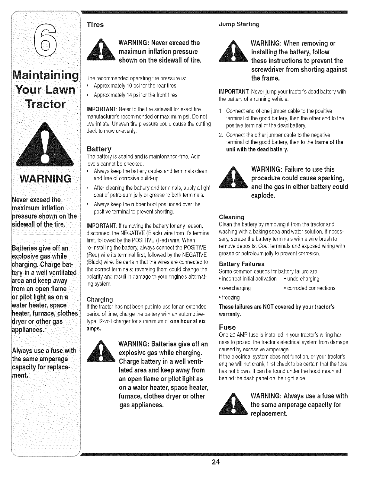
4. Lookingat the cuttingdeckfromthe leftsideof the
tractor,locatethe hairpinclip thatsecuresthe deck
supportrodon the rear left sideof thedeck. See
Figure22.
5. Removethe hairpin clipthatsecuresthedeck
supportrod, andcarefullyremovethe deck support
fromthedeck liftarm.
6. Repeatthe abovestepsonthe tractor'srightside.
7. Movethe decklift leverintothe top notchonthe right
fenderto raisethedeck lift arms up andout of the
way.
8. Carefullyremovethe PTOcablefromthe rearof
the cuttingdeck by removingthe hair pin clipwhich
securesit. Removethe springfrom the deck idler
bracket.SeeFigure23.
9. Gentlyslidethe cuttingdeck towardthefrontof the
tractorallowingthe hooksonthe deckto release
themselvesfromthedeck stabilizerrod.
10.Gentlyslidethe cuttingdeck (from the rightside)out
fromunderneaththetractor.
Figure 21
Figure 22
/ • /!
NOTE: Models
equippedwith a 38-inch
deck have one deck
idler pulley.Models
equippedwith a 42-inch
deck have two deck
idler pulleys.
Figure 23
23
3atteries give off an
_:xplosive gas while
;barging Charge bat-
tery in a well ventilated
area and keep away
from an open flame
or pilot light as on a
water heater, space
tleater, furnace, clothes
dryeror other gas
ippliances
Always use a fuse with
the same amperage
capacity for replace-
ment
Jump Starting
,_ WARNING: Never exceed the
maximum inflation pressure
shown on the sidewall of tire.
The recommendedoperatingtire pressureis:
,, Approximately10psi for the rear tires
,, Approximately14psi for the fronttires
iMPORTANT:Referto the tire sidewallforexacttire
manufacturer'srecommendedormaximumpsi. Do not
overinflate.Uneventire pressurecouldcausethe cutting
deckto mowunevenly.
Battery
The batteryis sealedandis maintenance-free.Acid
levelscannotbe checked.
• Alwayskeepthe batterycablesandterminalsclean
andfreeof corrosivebuild-up.
• Aftercleaningthe batteryand terminals,apply a light
coatof petroleumjelly or greasetoboth terminals.
• Alwayskeepthe rubberbootpositionedoverthe
positiveterminalto preventshorting.
IMPORTANT:If removingthe batteryforany reason,
disconnectthe NEGATIVE(Black)wire fromit's terminal
first,followedbythe POSITIVE(Red)wire.When
re-installingthe battery,alwaysconnectthe POSITIVE
(Red)wire its terminalfirst, followedbythe NEGATIVE
(Black)wire.Becertainthat thewiresareconnectedto
thecorrectterminals;reversingthemcould changethe
polarityandresultindamageto your engine'salternat-
ingsystem.
Charging
If thetractor hasnotbeenput into usefor an extended
periodof time,chargethe batterywith anautomotive-
type 12-voltchargerfor a minimumof one hour at six
amps.
WARNING: Batteries give off an
explosive gas while charging.
Charge battery in a well venti-
lated area and keep away from
an open flame or pilot light as
on a water heater, space heater,
furnace, clothes dryer or other
gas appliances.
WARNING: When removing or
installing the battery, follow
these instructions to prevent the
screwdriver from shorting against
the frame.
iMPORTANT:Neverjumpyourtractor'sdeadbatterywith
the batteryof a runningvehicle.
1. Connectend of one jumpercableto the positive
terminalof thegood battery,thenthe otherend to the
positiveterminalof the dead battery.
2. Connectthe otherjumpercableto the negative
terminalof thegood battery,thento the frame of the
unit withthe dead battery.
,,_ WARNING: Failure to use this
procedurecould cause sparking,
and the gas in either battery could
explode.
Cleaning
Cleanthe batteryby removingit fromthe tractorand
washingwitha bakingsodaand watersolution.If neces-
sary,scrapethe batteryterminalswitha wire brushto
removedeposits.Coatterminalsand exposedwiringwith
greaseor petroleumjelly topreventcorrosion.
Battery Failures
Somecommoncausesfor batteryfailureare:
,,incorrectinitialactivation ,,undercharging
,,overcharging ,,corrodedconnections
,,freezing
Thesefailures are NOTcoveredby yourtractor's
warranty.
Fuse
One20AMPfuse is installedin yourtractor'swiringhar-
nessto protectthe tractor'selectricalsystemfrom damage
causedby excessiveamperage.
If the electricalsystemdoes notfunction,oryour tractor's
enginewill not crank,first checkto becertainthatthe fuse
has notblown.It can befoundunderthe hoodmounted
behindthe dashpanelon the rightside.
_ ARNING: Always use a fuse with
the same amperage capacity for
replacement.
24
Cutting Blades f
WARNING: Be sure to shut
the engine off, remove ignition
key, disconnect the spark plug
wire(s) and ground against the
engine to prevent unintended
starting before removing the cut-
ting blade(s) for sharpening or
replacement. Protect your hands
by using heavy gloves or a rag to
grasp the cutting blade.
WARNING: Periodically inspect
the blade spindles for cracks or
damage, especially if you strike a
foreign object. Replace immedi-
ately if damaged.
Thebladesmayberemovedas follows.
1. Removethe deckfrombeneaththe tractor,(referto
CuttingDeckRemovalon page23) thengently flip
the deckoverto exposeits underside.
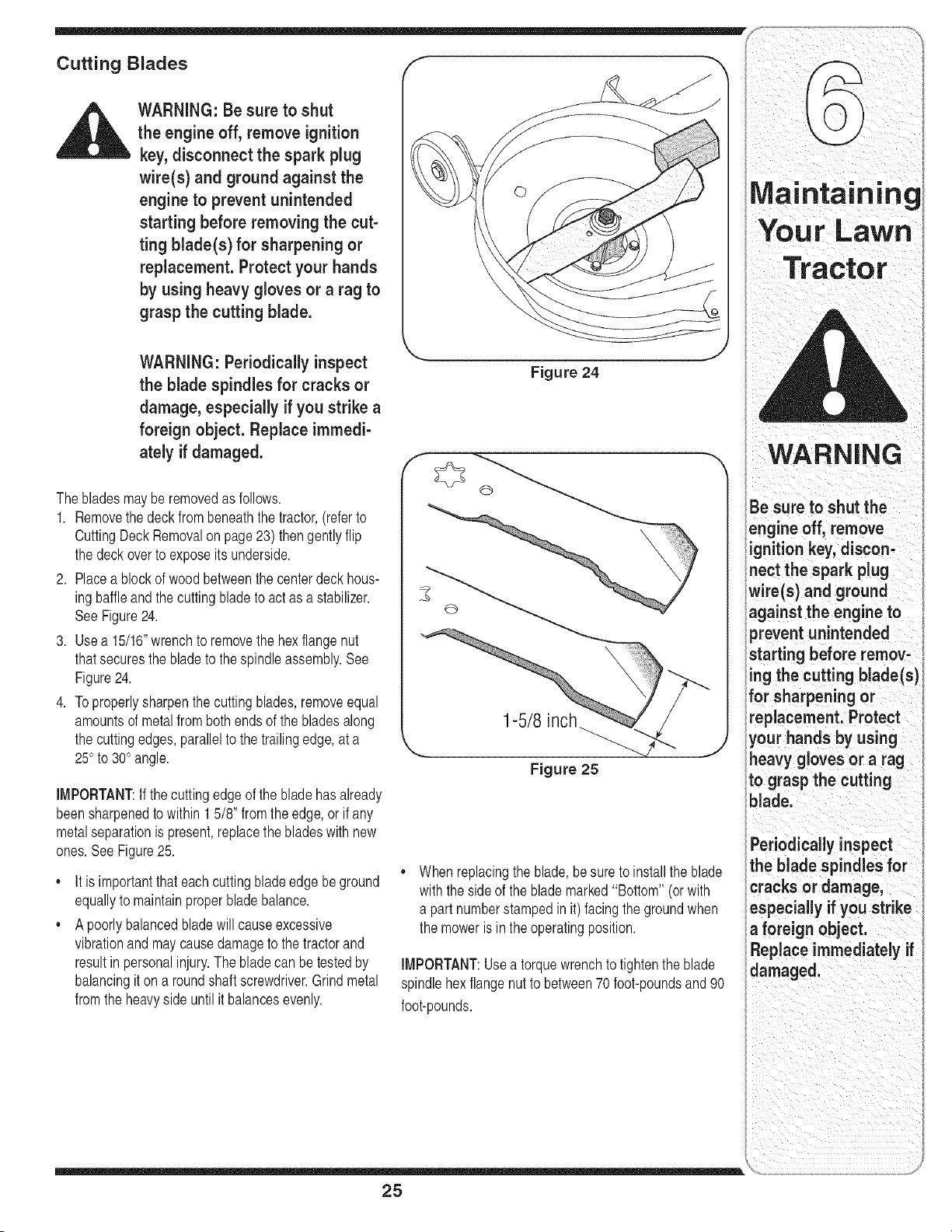
2. Placea blockof wood betweenthe centerdeckhous-
ingbaffleandthe cuttingbladeto act asa stabilizer.
SeeFigure24.
3. Use a 15/16"wrenchto removethe hexflangenut
thatsecuresthe bladeto thespindleassembly.See
Figure24.
4. Toproperlysharpenthe cutting blades,removeequal
amountsof metalfrom bothends of the bladesalong
the cuttingedges, parallelto the trailingedge,at a
25° to 30° angle.
IMPORTANT:If the cuttingedgeof the bladehasalready
beensharpenedto within15/8' fromthe edge,or if any
metalseparationis present,replacethe bladeswith new
ones.SeeFigure25.
o
o
It is importantthateachcuttingbladeedgebeground
equallyto maintainproperblade balance.
A poorlybalancedbladewill causeexcessive
vibrationand maycausedamageto thetractorand
resultinpersonalinjury.The bladecan be testedby
balancingit on a roundshaftscrewdriver.Grind metal
fromthe heavysideuntil it balancesevenly.
Figure 24
1-5/8
Figure 25
When replacingthe blade,be sure to installthe blade
with theside of the blademarked"Bottom"(or with
a part numberstampedin it) facing the groundwhen
the moweris inthe operatingposition.
IMPORTANT:Useatorquewrenchto tightenthe blade
spindlehex flangenutto between70 foot-poundsand 90
foot-pounds.
, ,',g
Your Lawn
j
Tractor
i
l
l
l
l
WARNING
I Be sure to shut the
lengine off, remove
iignition key, discon-
inect the spark plug
wire(s) and ground
against the engine to
_revent unintended
starting before remov-
ing the cutting blade(s)
for sharpening or
replacement. Protect
your hands by using
heavy gloves or a rag
to grasp the cutting
blade.
Periodicallyinspect
the blade spindles for
cracks or damage,
especially if you strike
a foreign object.
Replace immediately if
damaged.
25
Maintaining
Your Lawn
Tractor
WARNING
Be sure to shut the
engine off, remove ig-
nifion key, disconnect
the spark plugwire(s)
and ground against
the engine to prevent
unintended starting
before removing the
elt(s).
Avoid the possibility of
a pinching injury. Do
not place your fingers
on the idler spring or
between the belt and a
pulley while removing
the belt.
3/8" uareHole_
Figure 26
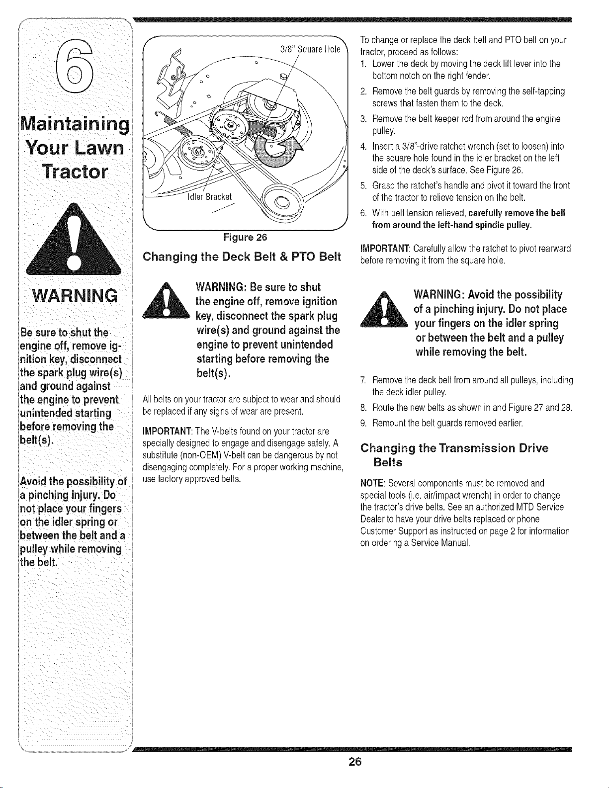
Changing the Deck Belt & PTO Belt
Tochangeor replacethedeck beltand PTObelt onyour
tractor,proceedas follows:
1. Lowerthe deckby movingthedeck liftleverinto the
bottomnotchon the rightfender.
2. Removethe beltguardsby removingthe self-tapping
screwsthatfastenthem to the deck.
3. Removethe beltkeeperrod fromaroundthe engine
pulley.
4. Inserta 3/8"-driveratchetwrench(setto loosen)into
the squarehole foundin the idlerbracketonthe left
sideof the deck'ssurface.SeeFigure26.
5. Graspthe ratchet'shandleand pivot it towardthe front
of the tractorto relievetensiononthe belt.
6. With belttensionrelieved,carefullyremovethe belt
from around the left-handspindlepulley.
IMPORTANT:Carefullyallowthe ratchetto pivotrearward
beforeremovingit from the squarehole.
_ WARNING: Be sure to shut
the engine off, remove ignition
-- key, disconnect the spark plug
wire(s) and ground against the
engine to prevent unintended
starting before removing the
belt(s).
Allbeltson yourtractorare subjectto wearandshould
bereplacedif anysignsof wearare present.
iMPORTANT:The V-beltsfoundon yourtractorare
speciallydesignedto engageanddisengagesafely.A
substitute(non-OEM)V-beltcan bedangerousby not
disengagingcompletely.Fora properworkingmachine,
usefactory approvedbelts.
_ WARNING: Avoid the possibility
of a pinching injury. Do not place
your fingers on the idler spring
or between the belt and a pulley
while removing the belt.
7. Removethe deckbelt fromaroundall pulleys,including
the deckidlerpulley.
8. Routethe newbeltsas shownin andFigure27 and28.
9. Remountthe beltguardsremovedearlier.
Changing the Transmission Drive
Belts
NOTE:Severalcomponentsmustbe removedand
specialtools(i.e.air/impactwrench)inorderto change
the tractor'sdrivebelts. Seean authorizedMTDService
Dealerto haveyour drivebelts replacedorphone
CustomerSupportas instructedon page 2 for information
onorderinga ServiceManual.
26
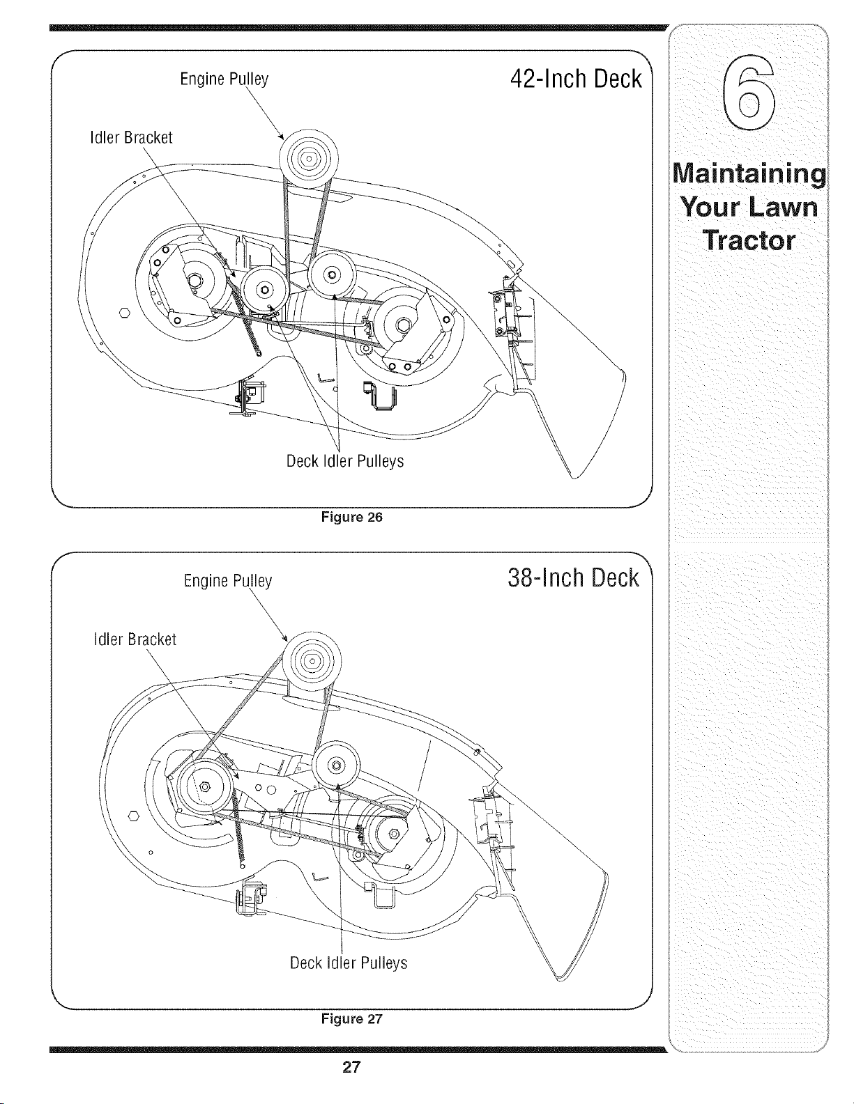
EnginePuny 42-Inch Deck
X
Idler Bracket
Deck Idler Pulleys
i
Figure 26
f
Engine Puny 38=InchDeck
X
Idler Bracket
\
Deck Idler Pulleys
_., .... J
Figure 27
27
Off-Season
Storag
Attachments
l
'WARNING
i Dra n fuel only into an
i
i approved container
i outdoors, away from
an open flame. AI-
i low engine to cool.
i Extinguish cigarettes,
_giclars, pples,and
other sources of Ignl-
ition prior to draining
Ifuel.
Never store the rea-
lchine or fuel container
i indoors where there =s
,,an openflame, spark
ior pUotlightsuch
ias on water heater,
!furnace, clothes dryer
for other gas appliance.
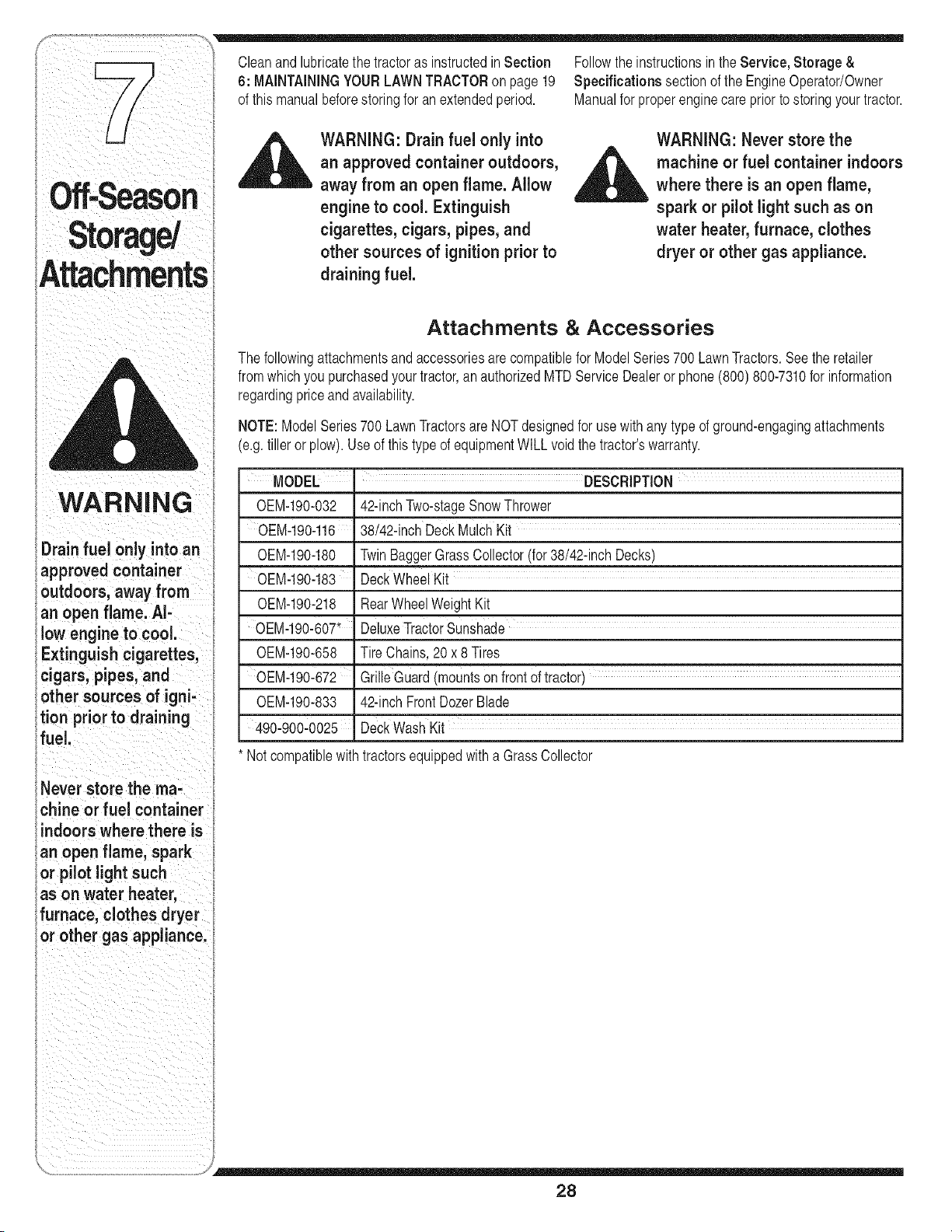
Cleanand lubricatethe tractoras instructedin Section Followthe instructionsin the Service, Storage &
6: MAINTAININGYOURLAWNTRACTORon page19 Specifications sectionof the EngineOperator/Owner
of thismanualbeforestoringfor anextendedperiod. Manualfor properenginecare prior to storingyourtractor.
,_1 WARNING: Drain fuel only into
an approved containeroutdoors,
away from an open flame. Allow
engine to cool. Extinguish
cigarettes, cigars, pipes, and
other sources of ignition prior to
draining fuel.
WARNING: Never store the
_ achine or fuel container indoors
where there is an open flame,
-- spark or pilot light such as on
water heater, furnace, clothes
dryer or other gas appliance.
Attachments & Accessories
The followingattachmentsandaccessoriesare compatiblefor ModelSeries700 LawnTractors.Seethe retailer
fromwhichyou purchasedyour tractor,an authorizedMTDServiceDealeror phone(800) 800-7310for information
regardingpriceand availability.
NOTE:ModelSeries700 LawnTractorsare NOTdesignedfor usewithany typeof ground-engagingattachments
(e.g.tiller or plow).Use of this type of equipmentWILLvoidthe tractor'swarranty.
MODEL ' DESCRiPTiON
0EM-190-032
0EM-190-116
0EM-190-180
OEM-190q83
0EM-190-218
0EM-190-607'
0EM-190-658
0EM-190-672
0EM-190-833
4.90-900-0025
42-inchTwo-stageSnowThrower
38/42-inchDeckMulch Kit
TwinBaggerGrassCollector(for38/42-inchDecks)
Deckwheel Kit
RearWheelWeightKit
DeluxeTractorSunshade
Tire Chains,20 x 8Tires
GrilleGuard(moUntsonfrontoftractor)
42-inchFrontDozerBlade
DeckWash Kit
Notcompatiblewith tractorsequippedwith a GrassCollector
28
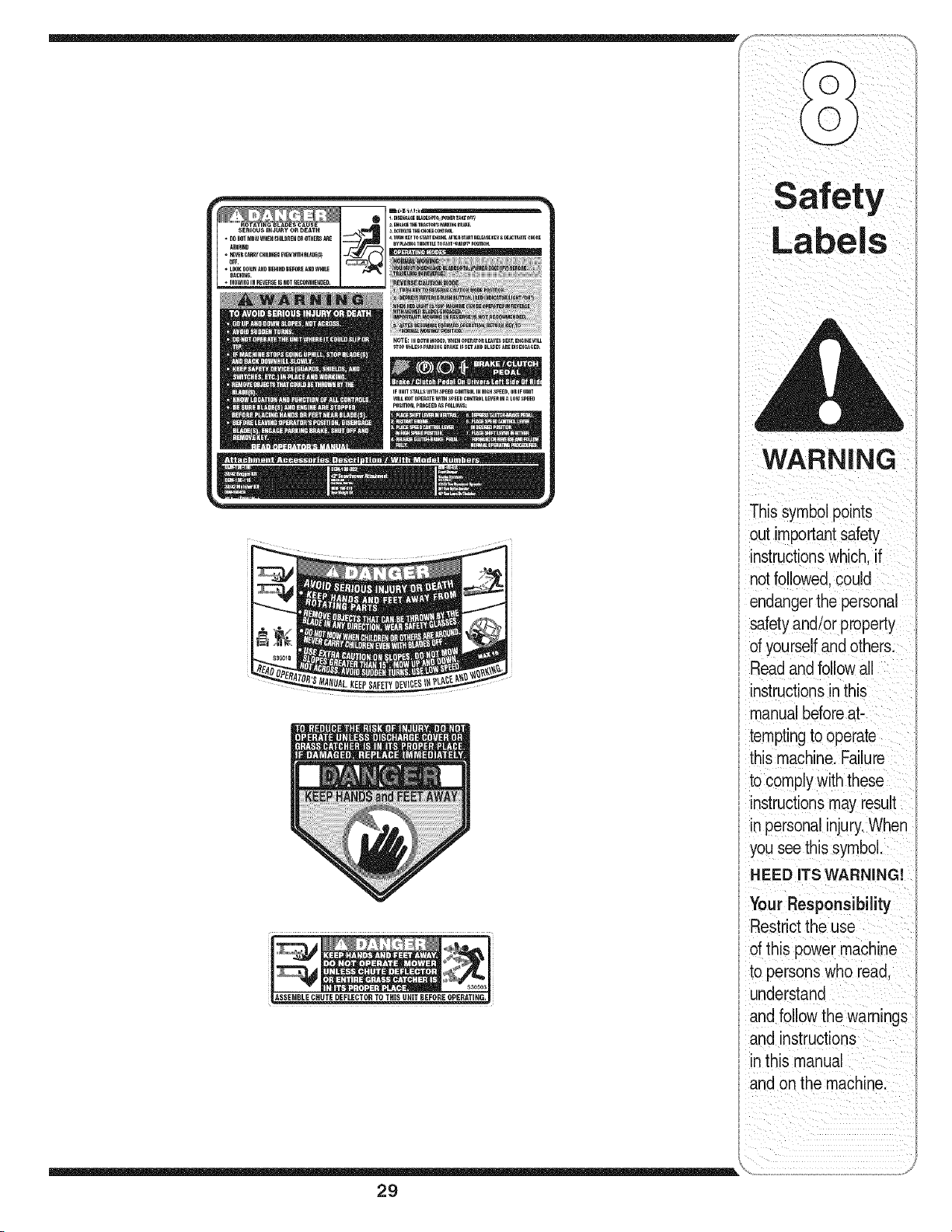
NOTE:IHBOTHMODE__I_ENOpER_TOnL_VESS_T, E_I_EWILL
STOPUNLESSP_KI_ _r_K_I_SLT_,D _L_E__R__S_,_ED.
IFUNnS_LLSwnHSr_EO¢OH_ROLINHIGHS_EO,ORIF UNn
WILLNOTOPERATEWnHSPEEnCONTROLLE_ IN_ LOWSP_E_
WARNING
Th s symbo points
out importantsafety
instructionswhich, if
notfollowed,could
endangerthe personal
safety and/or ppyroerr
of yourselfand others:
Readand follow all
instructions in this
manual beforeat
temptingto operate
th!s machine. Fa!lure
to comply with these
instructions may resu!t
in personal injurylwhen
you see this symbol.
HEED ITS WARNING!
Ii
Your ResponslbJhty
Restrictthe use
' of this power machine
' h ad
to persons w o re ,
understand
and follow the warnings
and instructions
in this manual
and on the machine:
29

'Trouble
Shooting
For repairs beyond
the minor adjust-
i merits listed here,
i contact an authorized
service dealer.
Problem Cause Remedy
Enginefails to Start 1. PTOengaged. !. PlacePTOknob(or lever)in
aisengaged(OFF)position,
2. spark plugwire(s)disconnected. 2: connect wire(s)to spa!k plug(s)i
3 FUeliankem t oistaiefuel 3 F tankwtheean freshgaso ne
py . , .
4 Chokenotactiated 4 Pu out the CHOKEcontro ( f so
V !
equipped)orplacethe throttle
€ontrolin CHOKEpositionl
5' Fau!tYsPa!kP!Ug' 5. Cleanl adjustgaPlerreplacel
&Blocke d fuel !ine• 6. clean iuel line Orreplacefueifilter,
7. Engineflooded, if so equipped.
7, Ciank enginewiththrottleinFAsT
PoSition.
8. Parkngbiake not engaged. &Engage parkingbrake,
9 T rotlecontiolie;er,,,,_i,,,,,,r,e .,; 9 Placethrottleleverto FAST
• h t v ,u_,uu,,_ :
startingposition, position.
Engine runs erratic 1. Unit runningwith CHOKEapplied. 1. PushCHOKEcontrol(if so
3. Blockedfuel lineor stale fuel.
4. Ventingas cap plugged.
5. Wateror dirt in fuel system.
6. Dirty air cleaner.
3O
equipped)in, or movethe throttle
controlout of the CHOKEposition.
2. Connectand tightenspark
plugwire(s).
3. Cleanfuel line;fill tank withclean,
fresh(lessthan30 daysold)
gasoline.Replacefuel filter,if so
equipped.
4. Clearventor replaceif damaged.
5. Drainfuel tank. Refillwith
freshfuel.
6. Replaceaircleanercartridge/ele-
mentor cleanpre-cleaner,if so
equipped.
2. Sparkplugwire(s)loose.
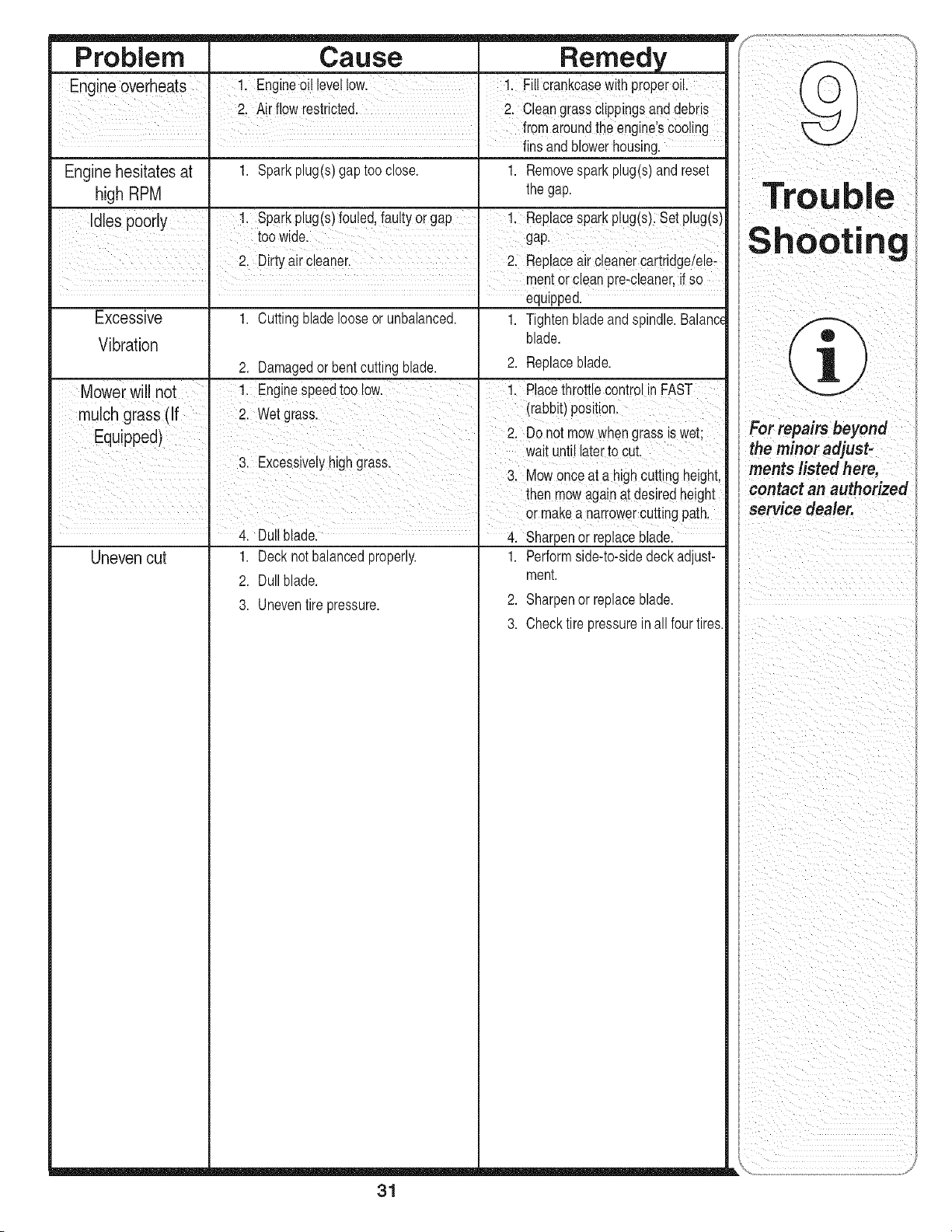
Problem Cause Remedy
Engine oveiheats Engine0il leve!!ow 1: Fi!I CrankcasewithproPer*0iL
2. Air flow restricted. " 2. Cleangrassclippingsanddebris
fr0maroundthe enginelscoo!ing
fns and b owerhousng.
Enginehesitates at 1. Sparkplug(s)gap tooclose. 1. Removespark plug(s)and reset
high RPM thegap.
Idles poorly !, Sparkplug(s)fouled,!aulty O!gap !. Rep acespark plug(s)i Set#!ug(s)
toowde i gap
I
2. Dirtyair cleaner. " 2, Repiaceaircleanercartridge/ele-
meritor €leanpre-c!eaner,if so
equipped.
Excessive 1. Cuttingblade looseor unbalanced. 1. Tightenbladeandspindle.Balance
Vibration blade.
2. Damagedor bentcutting blade. 2. Replaceblade.
Mowerwill not Enginespeedtoo !ow. 1. Placethrottle controlin FAST
mulch grass (if I 2. wet grass. (rabbit)position.
Equ pped) 2, Do not mowwhengrassiswet;
wat unt aterto cut
3. Excessivelyhighgrass.
3. MOWonce at a nign cuttingheight,
then rnowagainat desiredheight
°r makea nar!owerCUttingpath'
4. Du bade. Sharpenor replaceblade.
Uneven cut
1. Decknotbalancedproperly.
2. Dullblade.
3. Uneventire pressure.
1. Performside-to-sidedeckadjust-
ment.
2. Sharpenor replaceblade.
3. Checktire pressureinall fourtires.
31
Shooting
i
1
For repairs beyond
the minor adjust-
ments listed here,
contact an authorized
service dealer.
Ii
I

Useth_spagetomake
notes and write down •
!mportant mformat_on.
l
l
32

Use this page to make
notes and write down
impo_.ntin_orm.tion:
33

notes and write down
important information.
l
0
34

CALIFORNIA EMISSION CONTROL WARRANTY STATEMENT
YOUR WARRANTY RIGHTS AND OBLIGATIONS
The CaliforniaAir ResourcesBoardandMTDLLC are pleasedto explaintheevaporativeemissioncontrolsystemwarrantyon your2006 lawnmower.In California,
new lawnmowermust be designed,built and equippedto meetthe State'sstringentanti-smogstandards.MTD LLCmustwarranttheEECS onyour lawn mower
forthe periodof time listedbelow providedthere has beenno abuse,neglect or impropermaintenanceof your lawnmower.
YourEECSmayincludeparts such as thecarburetor,fuel-injectionsystem,the ignitionsystem,catalyticconverter,fuel tanks,fuel lines,fuel caps,valves,
canisters,filters,vapor hoses,clamps,connectors,and other associatedemission-relatedcomponents.
Whore a warrantable condition exists, MTDLLC will repair your lawn mower at no cost to you including diagnosis, parts and labor.
MANUFACTURER'S WARRANTY COVERAGE:
Thisevaporativeemissioncontrol systemis warrantedfor twoyears. If anyevaporativeemission-relatedpart onyour equipmentis defective,the partwill be
repairedor replacedby MTDLLC.
OWNER'S WARRANTY RESPONSIBILITIES:
Asthe lawn mowerowner,you are responsiblefor performanceof the requiredmaintenancelistedin yourowner'smanual. MTDLLC recommendsthatyou retain
all receiptscoveringmaintenanceon your lawnmower,but MTDLLCcannot denywarrantysolelyfor the lackof receipts.
Asthe lawn mowerowner,you shouldhoweverbe awarethat MTDLLC may denyyou warrantycoverageif your lawnmoweror a part has failed dueto abuse,
neglect,or impropermaintenanceorunapprovedmodifications.
Youare responsiblefor presentingyourlawn mowerto MTD LLC'sdistributioncenterorservicecenter as soonas the problemexists.The warrantyrepairsshould
be completedin a reasonableamountof time, not to exceed30 days.If you havea questionregardingyourwarrantycoverage,you shouldcontactthe MTD
ServiceDepartmentat 1-800-800-7310.
GENERAL EMISSIONS WARRANTY COVERAGE:
MTDLLCwarrantsto the ultimatepurchaserandeach subsequentpurchaserthatthe lawnmoweris:Designed,built andequipped soas to conform withall
applicableregulations;andfree from defectsin materialsand workmanshipthat causethe failure of a warrantedpart to be identicalin all materialrespectsto that
part as describedin MTDLLC's applicationfor certification.
The warrantyperiodbeginson the datethe lawnmoweris deliveredto an ultimatepurchaserorfirst placedinto service.Thewarranty period is twoyears.
Subjectto certain conditionsand exclusionsas statedbelow,the warrantyon emission-relatedparts is as follows:
1. Any warrantedpart that is not scheduledfor replacementas requiredmaintenanceinthe writteninstructionssupplied, is warrantedfor the warrantyperiod
statedabove. If the part fails duringthe periodof warrantycoverage,the partwill be repairedor replacedby MTDLLCaccordingto subsection(4) below.Any
such part repairedor replacedunderwarrantywill be warrantedfor the remainderof the period.
2. Any warrantedpart that is scheduledonly for regular inspectioninthe writteninstructionssuppliedis warrantedfor thewarranty periodstated above.Any such
part repairedor replacedunderwarrantywill bewarrantedfor the remainingwarrantyperiod.
3. Any warrantedpart that is scheduledfor replacementas requiredmaintenanceinthe written instructionssuppliedis warrantedfor the periodof time before
thefirst scheduledreplacementdate forthat part. If the part fails beforethe first scheduledreplacement,the part will be repairedor replacedby MTDLLC ac-
cordingto subsection(4) below.Any such part repairedor replacedunderwarrantywill bewarrantedforthe remainderof the periodpriorto thefirst scheduled
replacementpointfor the part.
4. Repairor replacementof any warrantedpart underthe warrantyprovisionshereinmustbe performedat a warrantystationat no chargeto the owner.
5. Notwithstandingthe provisionsherein,warrantyservicesor repairswill be providedat all of our distributioncentersthat arefranchisedto servicethe subject
enginesor equipment.
6. The lawnmowerowner will not be chargedfor diagnosticlaborthat is directlyassociatedwithdiagnosisof a defective,emission-relatedwarrantedpart,
providedthat such diagnosticwork is performedat a warrantystation.
7. MTDLLC is liablefor damagesto other engineor equipmentcomponentsproximatelycaused bya failure underwarrantyof any warrantedpart.
8. Throughoutthe lawnmowerwarrantyperiodstated above,MTDLLC will maintaina supplyof warrantedparts sufficientto meetthe expecteddemandfor such
parts.
9. Any replacementpart maybe usedinthe performanceof any warrantymaintenanceor repairsand mustbe providedwithoutchargeto the owner.Suchuse will
not reducethe warrantyobligationsof MTD LLC.
10.Add-onor modifiedpartsthat are not exemptedbythe Air ResourcesBoardmaynot be used.The use of any non-exemptedadd-onor modifiedparts by the
ultimatepurchaserwill be groundsfor disallowinga warrantyclaims. MTDLLCwill notbe liableto warrantfailures of warrantedparts causedby the useof a
non-exemptedadd-onor modifiedpart.
WARRANTED PARTS:
The repairor replacementof any warrantedpartotherwise eligiblefor warrantycoveragemaybe excludedfrom such warrantycoverageif MTDLLCdemonstrates
thatthe lawnmowerhas beenabused,neglected,or improperlymaintained,andthat suchabuse, neglect, orimpropermaintenancewasthe directcauseof the
needfor repairor replacementofthe part. That notwithstanding,any adjustmentof a componentthat has a factory installed,and properlyoperating,adjustment
limitingdevice is still eligiblefor warrantycoverage.The followingemissionwarrantyparts list arecovered:Fuel Line,Fuel LineClamps

MANUFACTURER'S LiMiTED WARRANTY FOR
Thelimitedwarrantyset forth belowis givenby MTDLLCwith respect
to new merchandisepurchasedand usedin the UnitedStates,its
possessionsandterritories.
"MTD"warrantsthisproductagainstdefectsin materialand workman-
shipfor a periodof two (2) yearscommencingon thedate of original
purchaseandwill,at itsoption,repairor replace,free of charge,any
partfound tobe defectivein materialsorworkmanship.This limitedwar-
rantyshallonlyapply if thisproducthas beenoperatedand maintained
inaccordancewith theOperator'sManualfurnishedwith the product,
andhas notbeensubjectto misuse,abuse,commercialuse, neglect,
accident,impropermaintenance,alteration,vandalism,theft, fire, water,
ordamagebecauseof otherperilor naturaldisaster.Damageresulting
fromthe installationor useof any part, accessoryor attachmentnot
approvedby MTDfor use with the product(s)coveredbythis manual
will voidyourwarrantyas to any resultingdamage.
Normalwearpartsare warrantedto befree fromdefectsinmaterialand
workmanshipfor aperiodof thirty (30) days fromthe date of purchase.
Normalwearparts include,butare notlimitedto itemssuch as: batter-
ies,belts,blades,bladeadapters,grassbags,riderdeckwheels,seats,
snowthrowerskidshoes,shaveplates,augerspiralrubberand tires.
HOW TO OBTAIN SERVICE: Warranty service is available, WITH
PROOFOF PURCHASE,through your local authorized service
dealer. To locate the dealer in your area, check your Yellow Pages,
or contact MTD LLC at RO. Box 361131,Cleveland, Ohio 44136-
0019, or call 1-800-800-7310or 1-330-220-4683 or log on to our
Web site at www.mtdproducts.com.
Thislimitedwarrantydoesnot providecoveragein the followingcases:
a. Theengineor componentpartsthereof.These itemsmaycarrya
separatemanufacturer'swarranty.Referto applicablemanufacturer's
warrantyfor termsand conditions.
b. Log splitterpumps,valves,andcylindershavea separateone year
warranty.
c. Routinemaintenanceitemssuch as lubricants,filters, blade
sharpening,tune-ups,brakeadjustments,clutchadjustments,deck
adjustments,andnormaldeteriorationof the exteriorfinish due to
useor exposure.
d. Servicecompletedbysomeoneotherthanan authorizedservice
dealer.
e. MTDdoesnot extendanywarrantyfor productssold or exported
outsideof the UnitedStates,its possessionsandterritories,except
thosesold throughMTD'sauthorizedchannelsof exportdistribution.
f. Replacementparts that are not genuineMTDparts.
g. Transportationchargesandservicecalls.
No impliedwarranty, includingany impliedwarranty of mer-
chantabilityof fitness for a particularpurpose,applies after the
applicable periodof expresswritten warranty above as to the
partsas identified.No other expresswarranty, whether written or
oral,exceptas mentioned above,givenby any personor entity,
includinga dealeror retailer,with respectto any product,shall
bind MTD.Duringthe periodof the warranty,the exclusiveremedy
is repair or replacementof the productas set forth above.
Theprovisionsas set forth inthis warranty providethe sole and
exclusiveremedyarising from the sale. MTDshallnot be liable
for incidentalor consequentialloss or damageincluding,without
limitation,expensesincurredfor substituteor replacement lawn
careservicesor for rental expensesto temporarily replace a
warranted product.
Somestatesdo notallowthe exclusionor limitationof incidentalor
consequentialdamages,or limitationsonhow longan impliedwarranty
lasts,so the aboveexclusionsor limitationsmaynotapply to you.
In no event shallrecoveryof any kindbegreaterthanthe amountof the
purchasepriceof the productsold. Alterationof safety features of
the product shall void this warranty. Youassumethe risk and liability
for loss,damage,or injuryto you and yourpropertyand/orto othersand
theirpropertyarisingout of the misuseor inabilityto usethe product.
This limitedwarrantyshallnot extendto anyoneotherthan the original
purchaserorto the personfor whomit was purchasedas a gift.
HOWSTATELAW RELATESTO THISWARRANTY:This limited
warrantygivesyou specificlegal rights,and youmayalso haveother
rightswhichvaryfromstateto state.
IMPORTANT:OwnermustpresentOriginalProofof Purchaseto obtain
warrantycoverage.
MTD LLC, P.O. BOX 361131 CLEVELAND, OHIO 44136-0019; Phone: 1-800-800-7310, 1-330-220-4683

