Loading ...
Loading ...
Loading ...
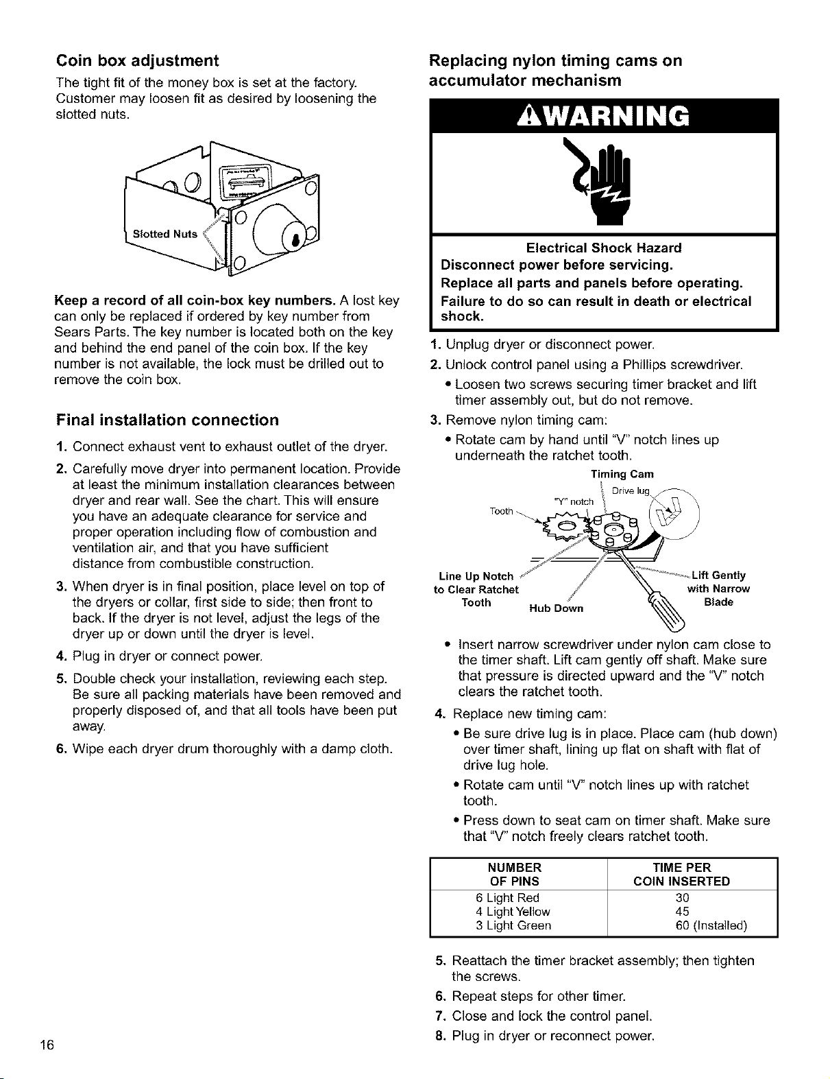
Coin box adjustment
The tight fit of the money box is set at the factory.
Customer may loosen fit as desired by loosening the
slotted nuts.
Keep a record of all coin-box key numbers. A lost key
can only be replaced if ordered by key number from
Sears Parts. The key number is located both on the key
and behind the end panel of the coin box. If the key
number is not available, the lock must be drilled out to
remove the coin box.
Final installation connection
1. Connect exhaust vent to exhaust outlet of the dryer.
2. Carefully move dryer into permanent location. Provide
at least the minimum installation clearances between
dryer and rear wall. See the chart. This will ensure
you have an adequate clearance for service and
proper operation including flow of combustion and
ventilation air, and that you have sufficient
distance from combustible construction.
3. When dryer is in final position, place level on top of
the dryers or collar, first side to side; then front to
back. If the dryer is not level, adjust the legs of the
dryer up or down until the dryer is level.
4. Plug in dryer or connect power.
5. Double check your installation, reviewing each step.
Be sure all packing materials have been removed and
properly disposed of, and that all tools have been put
away.
6. Wipe each dryer drum thoroughly with a damp cloth.
Replacing nylon timing cams on
accumulator mechanism
Electrical Shock Hazard
Disconnect power before servicing.
Replace all parts and panels before operating.
Failure to do so can result in death or electrical
shock.
1. Unplug dryer or disconnect power.
2. Unlock control panel using a Phillips screwdriver.
• Loosen two screws securing timer bracket and lift
timer assembly out, but do not remove.
3. Remove nylon timing cam:
• Rotate cam by hand until "V" notch lines up
underneath the ratchet tooth.
Timing Cam
Orive
lug
"Y" notch
-h
Line Up Notch ,' j _-k _Lift Gently
to Clear Ratchet ji _ with Narrow
Tooth Hub D0_wn % Blade
• Insert narrow screwdriver under nylon cam close to
the timer shaft. Lift cam gently off shaft. Make sure
that pressure is directed upward and the "V" notch
clears the ratchet tooth.
4. Replace new timing cam:
• Be sure drive lug is in place. Place cam (hub down)
over timer shaft, lining up flat on shaft with flat of
drive lug hole.
• Rotate cam until "V" notch lines up with ratchet
tooth.
• Press down to seat cam on timer shaft. Make sure
that "V" notch freely clears ratchet tooth.
NUMBER TIME PER
OF PINS COIN INSERTED
6 Light Red 30
4 Light Yellow 45
3 Light Green 60 (Installed)
16
5. Reattach the timer bracket assembly; then tighten
the screws.
6. Repeat steps for other timer.
7. Close and lock the control panel.
8. Plug in dryer or reconnect power.
Loading ...
Loading ...
Loading ...