Loading ...
Loading ...
Loading ...

OWNER’S MANUAL 1199797 REV 0 (6/14)
PAGE
13
OF 40
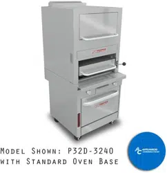
RADIANT BROILER
STEP 4: CONNECT BATTERY SECTIONS (OVEN BASE ONLY)
If the unit is part of a battery, and the battery was shipped partially disassembled, connect the battery sections using the
following procedure.
1. Remove valve panels from all sections. Mark them so that they can be returned to their respective section.
2. Position the center section of the battery and carefully level that unit. Use a long spirit level four ways; across front
top rail and the rear edge, and along each side edge.
3. If not already in place, attach pipe-union to front manifold of the battery. Screw it in far enough to be able to slide the
adjacent section into position.
4. Bring up adjacent section and level it using the same method and by using the center unit as reference. Match front
rails and rear edge. When a battery is set on a masonry base and legs are not used, shims may be used. Special
attention should be given to griddle tops to allow proper drainage.
5. Bolt the frames of the sections together.
6. Connect the front manifolds using the pipe-union.
7. Attach the trim-strip between the section tops.
8. Install the continuous front-rail, if ordered.
9. Slide control knobs onto their shafts (to operate the sections during the installation procedure), but do not yet
reattach valve panels or front-panel trim pieces.
STEP 5: CONNECT ELECTRICITY (OVEN BASE)
A wiring diagram is located behind the kick panel of the oven-base. Be sure that the input voltage and phase match the
requirements shown on the serial plate.
Oven-bases ordered with a 115V, 60Hz, single-phase electrical rating are factory-supplied with a three-wire cord with
a three-prong plug that ts any standard three-prong grounded receptacle. Each standard oven requires a 15 ampere
supply, while each convection oven requires a 20 ampere supply.
Oven-bases ordered with a 208/236V, 60Hz, single- or three-phase electrical rating are factory-equipped with a two-pole
terminal block located behind cover plate located on the rear of the unit. To connect the supply wires, remove the cover
plate. Route the supply wires and the grounding wire through the strain relief tting to the terminal block. Insert the supply
wires, one each, into the two poles of the terminal block and tighten the screws. Insert the ground wire into the grounding
lug and tighten the screw. Re-attach the cover plate.
Three phase units are wired as above, using only two supply wires. The third wire is not used and must be properly
terminated.
All units are shipped wired as specied by factory order. Conversion between single-phase and three-phase can be
accomplished by referring to phase loading and line amperes chart on the wiring diagram for wire size and ampere
requirements.
STEP 7: CONNECT GAS SUPPLY
If the Southbend equipment is being installed at over 2,000 feet altitude and that information was not specied when
ordered, contact the appropriate authorized Southbend Service Representative or the Southbend Service Department.
Failure to install with proper orice sizing will result in poor performance and may void the warranty.
Southbend equipment is design-certied for operation on natural or propane gases. The units are shipped congured and
adjusted for the type of gas specied by the purchaser, which is indicated on the serial plate (see Figure 1 and Figure 2).
Connect the equipment ONLY to the type of gas for which it is congured and adjusted.
Minimum supply pressure is 7” W.C. for natural gas, 11” W.C. for propane. An external pressure regulator and shut off
valve are provided. If using a exible-hose gas connection, the I.D. of the hose must not be smaller than the connector on
the equipment, and must comply with ANSI Z21.69. Provide an adequate means of restraint to prevent undue strain on
the gas connection.
INSTALLATION
Loading ...
Loading ...
Loading ...