Loading ...
Loading ...
Loading ...
STEP 8
Attach the base connection pole section (Part 5) using 4 threaded bolts and lock washers as shown in Figure 9.
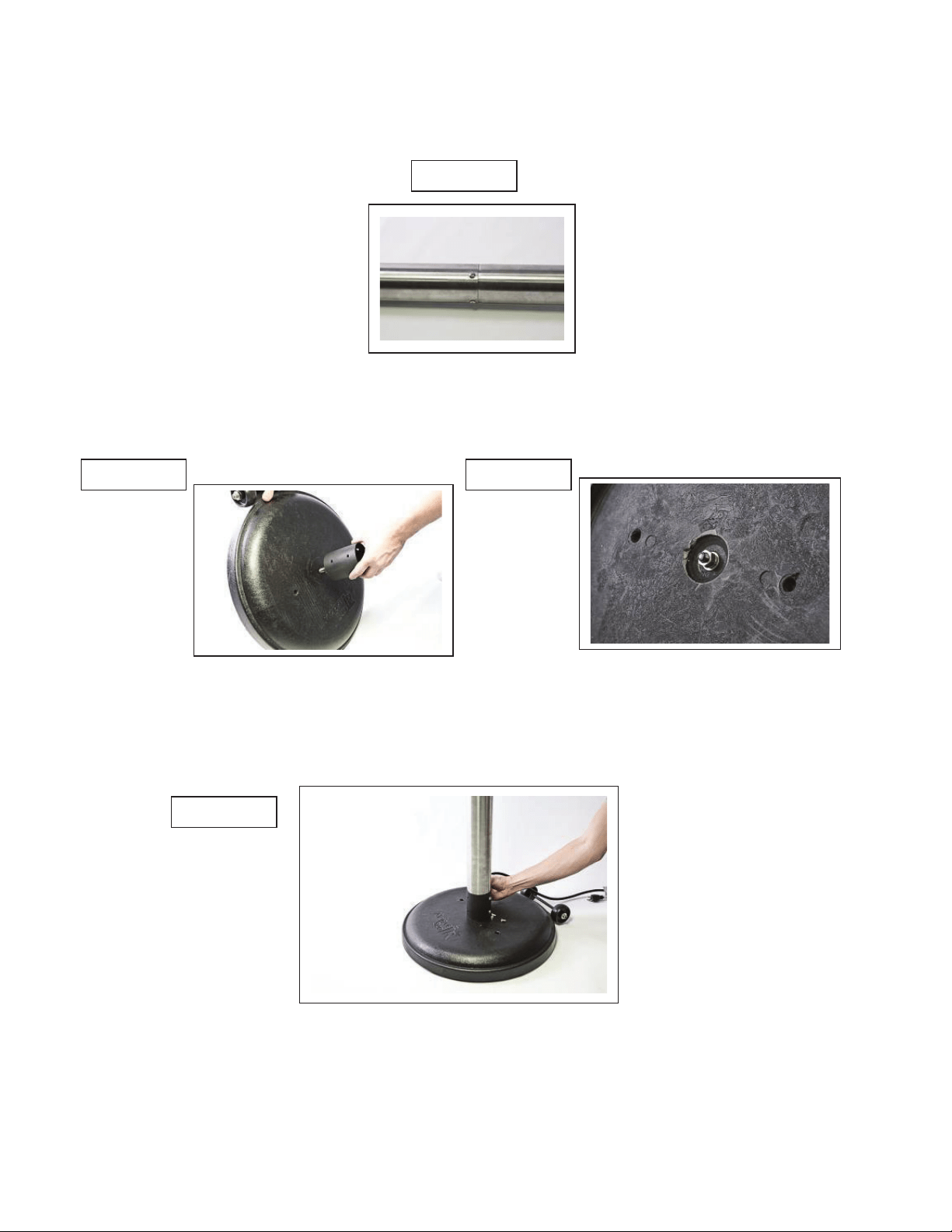
STEP 9
Mount support collar flange (Part 6) to base assembly with wheels (Part 7) as shown in Figure 10, and secure with
flat washer, lock washer, and ¾” bolt as shown in Figure 11.
STEP 10
Carefully lift pole and head unit assembly and insert lower end of pole into support collar flange (Part 6) as shown in
Figure 12. Secure with 6 threaded bolts and lock washers.
FIGURE 9
FIGURE 10
FIGURE 11
FIGURE 12
8
Loading ...
Loading ...
Loading ...