Loading ...
Loading ...
Loading ...
Part Number 550-142-302/0520
CGi
SERIES 4 — GAS-FIRED WATER BOILER — Boiler Manual
58
Troubleshooting — control module lights (cont.)
11c
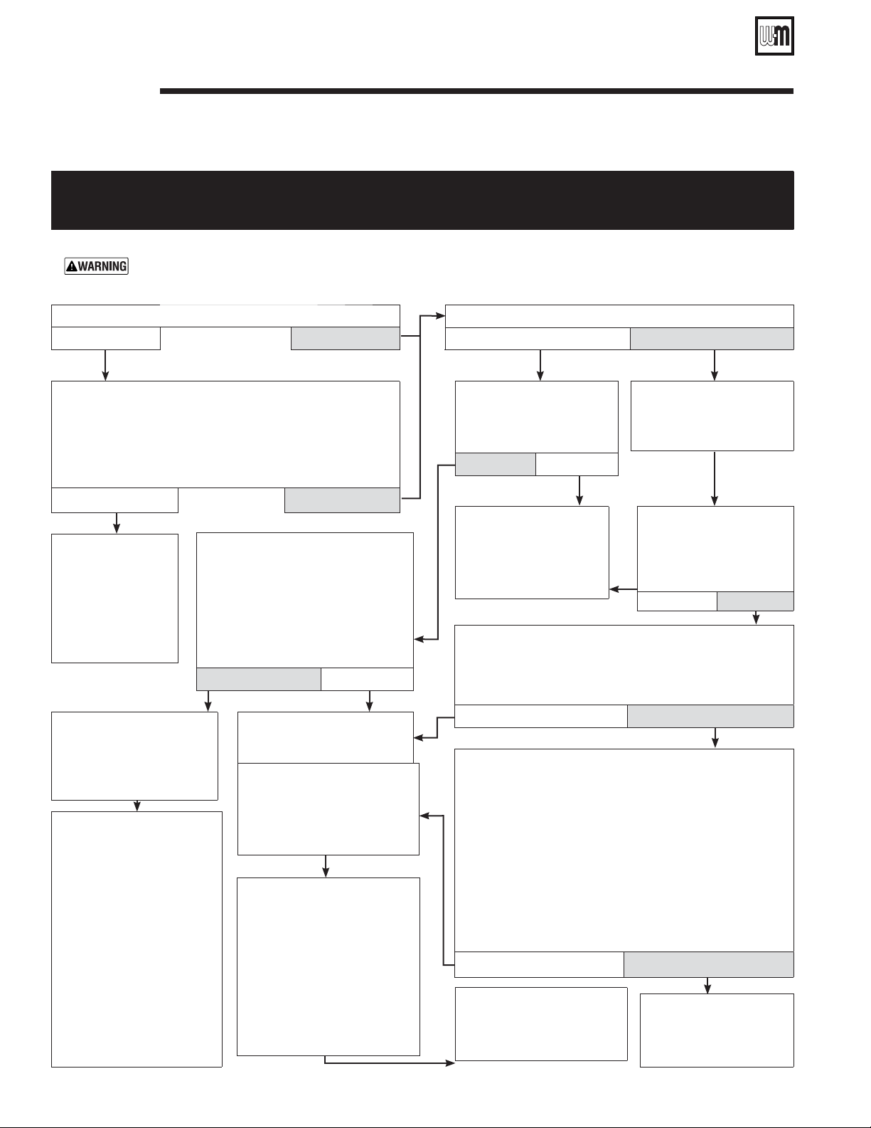
CHART 6 –– FLAME light flashing and Power light on steady
Also –– Troubleshooting failure to establish main flame.
Electrical shock hazardTURN OFF POWER
• Is pilot flame visible through inspection port ?
No Yes
Are main manual shutoff valve and gas valve open?
No Yes
•
to
boiler at service switch or
breaker.
• Remove burner shield (see
Figure 40, item 4, page 64
for location.
• Contact gas supplier to cor-
rect
pressure or gas supply.
• Check the voltage
across terminals PV and
C of the gas valve.
Is 24VAC present there?
Yes No
• Make sure ground wire
terminal is securely
fastened to control module
mounting screw.
• Verify inlet gas pressure at gas valve:
Natural gas – 5.0” w.c. min/14.0” w.c. max
Propane – 11.0” w.c. min/14.0” w.c. max
No Yes
• Check the voltage
across terminals of MV
and C
of the gas valve.
Is 24VAC present there?
No Yes
• If the wiring from the
control module to gas
valve is intact, replace the
control module.
• Retest.
• Verify inlet gas pressure at gas
valve:
Natural gas – 5.0” w.c. min/14.0”
w.c. max
Propane – 11.0” w.c. min/14.0”
w.c. max
Is gas present at gas valve inlet and
Yes No
• Boiler should be in
normal operating
sequence.
• Observe operation
until thermostat is
satisfied and blower
has completed its
post-purge cycle.
• Verify pilot gas line is not
kinked, obstructed or
damaged and is correctly
attached to pilot and gas
valve.
• Verify pilot ignition electrode,
electrode ceramic and spark
lead wire from control are in
good condition. Spark gap
should be approximately 1/8”.
• Correct any above problems,
replacing pilot if burner or
wiring is damaged.
• Reinstall burner shield to
operate boiler for retest after
any changes or corrections.
• If none of the above corrects
problems, then replace the
control module and retest.
•
to boiler at service switch or
breaker.
• Remove burner shield (see
Figure 40, item 4, page 64
for location.
• If none of the previous steps
(including replacing pilot)
corrects problem, then replace
the control module, reinstall
burner shield and retest.
• If the wiring from the
control module to gas
valve is intact, replace the
control module and retest.
•
to boiler at service switch or breaker.
• Open main manual shutoff valve and boiler gas valve (per
Operating instructions in this manual). Wait at least 45 seconds.
• Turn on power at service switch or breaker. Allow boiler to
cycle .
Does FLAME
No Yes
•
to boiler at service switch or breaker.
• Check flame signal – Detach sense lead from ignition control
(Figure 38, Item 8, page 52)
.
• Connect negative lead of MICROAMMETER to control
sense terminal
(Figure 38, Item 8, page 52)
. Connect
positive lead of MICROAMMETER to sense wire.
• DISCONNECT red wire connected to terminal MV of the gas
valve.
• Turn on power to boiler and allow to cycle. As soon as pilot
is burning, the MICROAMMETER should read at least 1.0
microamp.
No Yes
• Verify pilot burner is securely
attached to pilot bracket, brack-
et is securely attached to cross
tie, and there is no corrosion on
the parts which would affect the
ground path for flame sense.
• Verify that pilot flame rod, flame
rod ceramic and lead wire from
control module to flame rod are
in good condition.
• Correct any above problems,
replacing pilot if burner or wir-
ing is damaged.
Loading ...
Loading ...
Loading ...