Loading ...
Turn o power to your appliance before you remove or
replace the knobs.
Work with one knob at a time to ensure you don’t mix up
replacement pieces.
Make sure you check the writing on each of your knobs
(and/or bezels) and set them out in the order you will
replace them. This will help ensure you don’t put them
on in the wrong order.
If your appliance has an oven, you will need to replace
the bezels and Oven Mode Selector. If your appliance
does NOT have an oven, you will only have to replace
the knobs and bezels.
IMPORTANT!
Instructions for Replacing Knobs with Bezels and Mode Selectors
Instrucciones En Español | Instructions En Français:
www.cafeappliances.com/custom-hardware/installation/
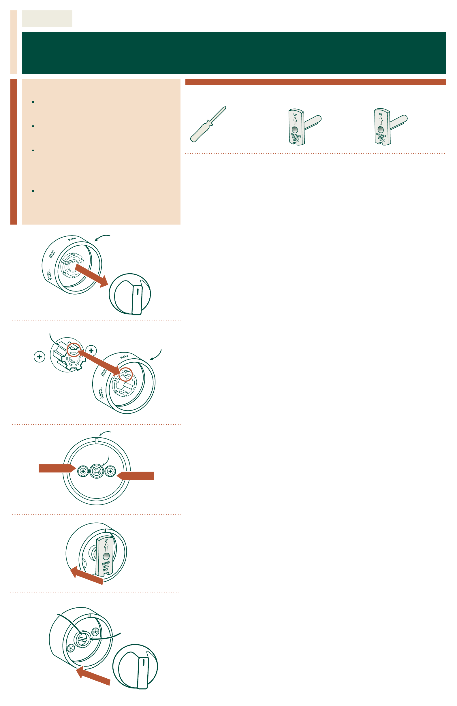
Phillips Head Screwdriver
(Not included)
Tools You Will Need:
I. Oven Mode Selector
1. Make sure all knobs are in the OFF position
2. Determine if your unit has an Oven Mode Selector (fig. 1). If your unit does not have an
Oven Mode Selector, skip to Section II.
3. First, remove the knob on the Oven Mode Selector by pulling it free from the shaft. You
may have to wiggle it slightly as you pull (fig. 1).
4. Then, grasp the sides and rear of the Oven Mode selector and pull firmly away from
the appliance until it’s free from the Oven Controls Shaft.
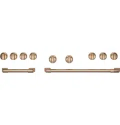
5. Your kit may come with more than one Oven Mode Selector. Make sure you choose
the correct one from the kit by checking the wording on the removed Oven Mode
Selector and matching it to the replacement Oven Mode Selector.
6. Align bigger tab on oven control shaft to the bigger slot on the oven mode selector,
then center it over the oven control shaft. Push onto the shaft as far as possible (fig. 2).
7. Next, match the replacement knob with the knob you’ve removed—make sure they
have the same writing and markings.
8. Hold the replacement knob so that the indicator is at the top and it lines up properly
with the shaft, then push the knob onto the shaft as far as possible for a snug fit.
II. Removing the Current Knobs and Bezels
1. Make sure all knobs are in the OFF position.
2. Choose which knob you will work with first, and remove it by grasping the sides and
pulling away from the appliance until the knob is free from its shaft. You may have to
wiggle it slightly as you pull.
3. Using a Phillips head screwdriver, remove the two bezel attachment screws.
4. You should be able to remove the bezel from the appliance front after the screws
have been removed.
5. Repeat the above removal steps for all burner and griddle bezels.
III. Installation of the Replacement Knobs and Bezels
Repeat the following steps 1 - 6 using the Burner and Griddle Bezel Tools to install all
knobs and bezels. Use the Burner Bezel Tool when installing burner knobs and the Griddle
Bezel Tool when installing the griddle knob (on some models).
1. Using the Burner/Griddle Bezel Tool, align the arrow on the tool with the indicator
notch on the bezel, and insert the tool into the bezel.
2. Push the Burner/Griddle Bezel Tool and bezel onto the valve shaft with indicator notch
and arrow pointing upward. Press tool onto the shaft until it is snug and release (fig. 4).
3. Drive the two bezel attachment screws into the bezel. (Partially drive the first screw,
fully drive the second screw, then fully drive the first screw.)
4. Remove the Burner/Griddle Bezel Tool.
5. Match the replacement knob with the knob you’ve removed. Make sure they have the
same writing and markings.
6. Hold the replacement knob so that the indicator is at the top and it lines up properly
with the shaft. Push the knob onto the shaft as far as possible so it fits snugly (fig. 5).
7. Press the knob and rotate to ensure normal operation. If the knobis dicult to push
in or rotate, visually check if the valve stem is centered within the bezel hole. If the
valve shaft is not centered, loosen the bezel screws, reposition the bezel to be
centered to valve shaft, then retighten screws.
fig. 3
fig. 4
fig. 2
fig. 1
31-2000914 05-21
Burner Bezel Tool
Included with Bezel)
fig. 5
REMOVE
REMOVE
Indicator notch
Valve Shaft
Oven Mode Selector
Griddle Bezel Tool
(Included with Bezel)
Oven Controls Shaft
Oven Mode Selector
ALIGN
or
Valve Shaft
Bezel Hole